CN102866494A - Holographic microscopy for trapping three-dimensional structure - Google Patents
Holographic microscopy for trapping three-dimensional structure Download PDFInfo
- Publication number
- CN102866494A CN102866494A CN2012103519707A CN201210351970A CN102866494A CN 102866494 A CN102866494 A CN 102866494A CN 2012103519707 A CN2012103519707 A CN 2012103519707A CN 201210351970 A CN201210351970 A CN 201210351970A CN 102866494 A CN102866494 A CN 102866494A
- Authority
- CN
- China
- Prior art keywords
- image
- dimensional
- laser beam
- trapped
- light
- Prior art date
- Legal status (The legal status is an assumption and is not a legal conclusion. Google has not performed a legal analysis and makes no representation as to the accuracy of the status listed.)
- Pending
Links
Images


Classifications
-
- G—PHYSICS
- G03—PHOTOGRAPHY; CINEMATOGRAPHY; ANALOGOUS TECHNIQUES USING WAVES OTHER THAN OPTICAL WAVES; ELECTROGRAPHY; HOLOGRAPHY
- G03H—HOLOGRAPHIC PROCESSES OR APPARATUS
- G03H1/00—Holographic processes or apparatus using light, infrared or ultraviolet waves for obtaining holograms or for obtaining an image from them; Details peculiar thereto
- G03H1/0005—Adaptation of holography to specific applications
-
- G—PHYSICS
- G01—MEASURING; TESTING
- G01B—MEASURING LENGTH, THICKNESS OR SIMILAR LINEAR DIMENSIONS; MEASURING ANGLES; MEASURING AREAS; MEASURING IRREGULARITIES OF SURFACES OR CONTOURS
- G01B9/00—Measuring instruments characterised by the use of optical techniques
- G01B9/02—Interferometers
- G01B9/021—Interferometers using holographic techniques
-
- G—PHYSICS
- G02—OPTICS
- G02B—OPTICAL ELEMENTS, SYSTEMS OR APPARATUS
- G02B21/00—Microscopes
- G02B21/32—Micromanipulators structurally combined with microscopes
-
- G—PHYSICS
- G03—PHOTOGRAPHY; CINEMATOGRAPHY; ANALOGOUS TECHNIQUES USING WAVES OTHER THAN OPTICAL WAVES; ELECTROGRAPHY; HOLOGRAPHY
- G03H—HOLOGRAPHIC PROCESSES OR APPARATUS
- G03H1/00—Holographic processes or apparatus using light, infrared or ultraviolet waves for obtaining holograms or for obtaining an image from them; Details peculiar thereto
- G03H1/04—Processes or apparatus for producing holograms
- G03H1/0443—Digital holography, i.e. recording holograms with digital recording means
-
- G—PHYSICS
- G02—OPTICS
- G02B—OPTICAL ELEMENTS, SYSTEMS OR APPARATUS
- G02B21/00—Microscopes
- G02B21/0004—Microscopes specially adapted for specific applications
- G02B21/0088—Inverse microscopes
-
- G—PHYSICS
- G03—PHOTOGRAPHY; CINEMATOGRAPHY; ANALOGOUS TECHNIQUES USING WAVES OTHER THAN OPTICAL WAVES; ELECTROGRAPHY; HOLOGRAPHY
- G03H—HOLOGRAPHIC PROCESSES OR APPARATUS
- G03H1/00—Holographic processes or apparatus using light, infrared or ultraviolet waves for obtaining holograms or for obtaining an image from them; Details peculiar thereto
- G03H1/04—Processes or apparatus for producing holograms
- G03H1/08—Synthesising holograms, i.e. holograms synthesized from objects or objects from holograms
- G03H1/0866—Digital holographic imaging, i.e. synthesizing holobjects from holograms
-
- G—PHYSICS
- G03—PHOTOGRAPHY; CINEMATOGRAPHY; ANALOGOUS TECHNIQUES USING WAVES OTHER THAN OPTICAL WAVES; ELECTROGRAPHY; HOLOGRAPHY
- G03H—HOLOGRAPHIC PROCESSES OR APPARATUS
- G03H1/00—Holographic processes or apparatus using light, infrared or ultraviolet waves for obtaining holograms or for obtaining an image from them; Details peculiar thereto
- G03H1/22—Processes or apparatus for obtaining an optical image from holograms
- G03H1/2294—Addressing the hologram to an active spatial light modulator
-
- G—PHYSICS
- G03—PHOTOGRAPHY; CINEMATOGRAPHY; ANALOGOUS TECHNIQUES USING WAVES OTHER THAN OPTICAL WAVES; ELECTROGRAPHY; HOLOGRAPHY
- G03H—HOLOGRAPHIC PROCESSES OR APPARATUS
- G03H1/00—Holographic processes or apparatus using light, infrared or ultraviolet waves for obtaining holograms or for obtaining an image from them; Details peculiar thereto
- G03H1/0005—Adaptation of holography to specific applications
- G03H2001/0033—Adaptation of holography to specific applications in hologrammetry for measuring or analysing
-
- G—PHYSICS
- G03—PHOTOGRAPHY; CINEMATOGRAPHY; ANALOGOUS TECHNIQUES USING WAVES OTHER THAN OPTICAL WAVES; ELECTROGRAPHY; HOLOGRAPHY
- G03H—HOLOGRAPHIC PROCESSES OR APPARATUS
- G03H1/00—Holographic processes or apparatus using light, infrared or ultraviolet waves for obtaining holograms or for obtaining an image from them; Details peculiar thereto
- G03H1/0005—Adaptation of holography to specific applications
- G03H2001/0077—Adaptation of holography to specific applications for optical manipulation, e.g. holographic optical tweezers [HOT]
-
- G—PHYSICS
- G03—PHOTOGRAPHY; CINEMATOGRAPHY; ANALOGOUS TECHNIQUES USING WAVES OTHER THAN OPTICAL WAVES; ELECTROGRAPHY; HOLOGRAPHY
- G03H—HOLOGRAPHIC PROCESSES OR APPARATUS
- G03H1/00—Holographic processes or apparatus using light, infrared or ultraviolet waves for obtaining holograms or for obtaining an image from them; Details peculiar thereto
- G03H1/04—Processes or apparatus for producing holograms
- G03H1/0443—Digital holography, i.e. recording holograms with digital recording means
- G03H2001/0447—In-line recording arrangement
-
- Y—GENERAL TAGGING OF NEW TECHNOLOGICAL DEVELOPMENTS; GENERAL TAGGING OF CROSS-SECTIONAL TECHNOLOGIES SPANNING OVER SEVERAL SECTIONS OF THE IPC; TECHNICAL SUBJECTS COVERED BY FORMER USPC CROSS-REFERENCE ART COLLECTIONS [XRACs] AND DIGESTS
- Y10—TECHNICAL SUBJECTS COVERED BY FORMER USPC
- Y10S—TECHNICAL SUBJECTS COVERED BY FORMER USPC CROSS-REFERENCE ART COLLECTIONS [XRACs] AND DIGESTS
- Y10S359/00—Optical: systems and elements
- Y10S359/902—Holographic interferometer
Landscapes
- Physics & Mathematics (AREA)
- General Physics & Mathematics (AREA)
- Engineering & Computer Science (AREA)
- Computing Systems (AREA)
- Theoretical Computer Science (AREA)
- Chemical & Material Sciences (AREA)
- Analytical Chemistry (AREA)
- Optics & Photonics (AREA)
- Holo Graphy (AREA)
- Microscoopes, Condenser (AREA)
Abstract
被全息捕获三维结构的全息显微术。一种用于进行光学捕获的结构的三维全息显微术的方法和系统。该方法和系统使用倒置光学显微镜,使用产生捕获激光束的激光光源,其中该激光束被物镜聚焦成多个光陷阱。该方法和系统还使用成像波长上的准直激光器,照明由光陷阱建立的结构。由光学捕获的结构散射的成像光形成全息图,该全息图由视频摄像机成像并用光学形式体系进行分析,以确定光场,再现3-D像,供分析和评估。
Holographic microscopy of three-dimensional structures that are holographically captured. A method and system for three-dimensional holographic microscopy of optically trapped structures. The method and system use an inverted optical microscope using a laser light source that produces a trapping laser beam that is focused by an objective lens into a plurality of optical traps. The method and system also illuminate the structure created by the optical trap using a collimated laser at the imaging wavelength. Imaging light scattered by the optically trapped structures forms a hologram that is imaged by a video camera and analyzed with an optical formalism to determine the light field and reproduce a 3-D image for analysis and evaluation.
Description
本申请是申请日为2008年1月25日、申请号为200880003125.2、发明名称为“用于光学捕获和材料检查的全息显微系统和方法”一案的分案申请。This application is a divisional application with the filing date of January 25, 2008, the application number of 200880003125.2, and the title of the invention "Holographic Microscopic System and Method for Optical Capture and Material Inspection".
交叉参考相关申请Cross Reference Related Applications
本申请根据35U.S.C.119(e),要求2007年1月26日提交的美国申请60/897,784的权益,在此全文引用该申请,供参考。This application claims the benefit of US Application 60/897,784, filed January 26, 2007, under 35 U.S.C. 119(e), which application is hereby incorporated by reference in its entirety.
依照国家科学基金(National Science Foundation)资助编号DBI-0629584和资助编号DMR-0606415的资助,美国政府在本发明中具有确定的权利。The US Government has certain rights in this invention pursuant to grants from the National Science Foundation Grant No. DBI-0629584 and Grant No. DMR-0606415.
本发明针对全息光学捕获系统,该系统使用由计算机建立的全息图所产生的光陷阱,来组织材料,并以三维(3-D)方式应用显微镜光学装置,来检查和分析该材料。更具体地说,是一种全息视频显微镜系统,它使用实时分辨的3-D微结构的体积像,完成材料组合的分析和检查。The present invention is directed to a holographic optical trapping system that uses optical traps created by computer created holograms to organize material and applies microscope optics in three dimensions (3-D) to inspect and analyze the material. More specifically, a holographic video microscopy system that uses real-time resolved 3-D volumetric images of microstructures for the analysis and inspection of material assemblies.
背景技术 Background technique
全息光学捕获使用计算机产生的全息图,捕获微米尺度的物体并将其组织成任意的三维配置。在用于检验光学捕获的结构的现有技术中,除常规的两维显微术外,尚没有补充的方法可供使用。对各种应用,诸如,在把全息组织的系统固定在适当位置前,验证这些系统的结构,三维成像是有用的。对互作用地处理及检查三维结构的物体,诸如生物试样,三维成像也是有用的。综合三维成像与全息捕获,看来是直截了当的,因为两种技术都能使用相同的物镜,分别收集和投射激光器的光。但是,常规的三维成像方法,诸如共焦显微术,需要在机械上平移焦平面通过样品。但是,全息阱是相对于焦平面定位的,也一样需要移动。捕获图形必需平移,以补偿显微镜的机械运动,这样将大大增加复杂性,极大地降低成像速度,及可能弄碎接受检验和分析的样品。Holographic optical trapping uses computer-generated holograms to capture and organize micron-scale objects into arbitrary three-dimensional configurations. In the state of the art for examining optically trapped structures, no complementary methods are available other than conventional two-dimensional microscopy. Three-dimensional imaging is useful for various applications, such as verifying the structure of holographically organized systems before fixing them in place. Three-dimensional imaging is also useful for interactively manipulating and examining three-dimensional structures of objects, such as biological samples. Integrating 3D imaging with holographic capture seems straightforward, since both techniques can use the same objective lens to collect and project light from the laser, respectively. However, conventional three-dimensional imaging methods, such as confocal microscopy, require mechanical translation of the focal plane through the sample. However, the holographic well is positioned relative to the focal plane and needs to be moved as well. The capture pattern must be translated to compensate for the mechanical movement of the microscope, which adds significant complexity, greatly reduces imaging speed, and can shatter the sample being inspected and analyzed.
发明内容 Contents of the invention
数字全息显微术解决现有技术的所有问题,给出实时三维(3-D)成像数据,无需任何机械运动,包含不必平移焦平面通过受分析的样品。同轴全息显微术特殊的可兼容的多样性,用准直激光器代替亮场显微镜中的常规照明器。被物体散射出激光束的光,与入射照明的剩余部分干涉,产生外差散射图形,该外差散射图形被物镜放大并用视频摄像机记录。只要该干涉图形没有被许多光散射弄模糊,那么它就包含有关该散射体的三维配置的全面信息。在得到的视频流中每一幅两维瞬态图,都是对时间分辨体积信息的编码,该时间分辨体积信息能够被直接分析,或数值解码为三维表示。该系统和方法能实现在全息光学处理系统中的数字全息显微术的迅速商业利用,且该系统和方法使用组合的能力,直接评定两种技术的精度并建立任何限制。Digital holographic microscopy solves all the problems of the prior art, giving real-time three-dimensional (3-D) imaging data without any mechanical movement, including without having to translate the focal plane through the sample being analyzed. Special Compatible Diversity of Coaxial Holographic Microscopy, Replacement of Conventional Illuminators in Brightfield Microscopy with Collimated Lasers. Light scattered out of the laser beam by the object interferes with the remainder of the incident illumination to produce a heterodyne scatter pattern that is magnified by the objective and recorded with a video camera. As long as the interference pattern is not obscured by much light scattering, it contains comprehensive information about the three-dimensional configuration of the scatterer. Each two-dimensional snapshot in the resulting video stream encodes time-resolved volume information that can be directly analyzed or numerically decoded into a three-dimensional representation. The system and method enable rapid commercial deployment of digital holographic microscopy in holographic optical processing systems and use the combined ability to directly assess the accuracy of both techniques and establish any limitations.
本发明的各种细节方面在本文后面描述,而本发明的这些和其他改进及特征,则在本文后面详细描述,其中包括下面一段中对附图的说明。Various detailed aspects of the invention are described hereinafter, and these and other improvements and features of the invention are described in detail hereinafter, including a description of the drawings in the following paragraphs.
附图说明 Description of drawings
图1表明按照本发明构建的系统;Figure 1 shows a system constructed in accordance with the present invention;
图2A表明,在xy平面中捕获的5个胶体球(标尺为5微米)的常规亮场像;图2B表明图2A绕y轴旋转45°的图形;图2C表明在xy平面中看到的图2B旋转的图形的亮场像;图2D表明在xy平面中看到的相同结构的相干像;而图2E表明,通过该倾斜图形的xz截片的全息再现(圆圈标明所指粒子的坐标)。Figure 2A shows a conventional bright-field image of five colloidal spheres (5 μm scale) captured in the xy plane; Figure 2B shows the image of Figure 2A rotated 45° around the y-axis; Figure 2C shows the image seen in the xy plane Fig. 2B is a bright-field image of the rotated pattern; Fig. 2D shows the coherent image of the same structure seen in the xy plane; and Fig. 2E shows the holographic reconstruction of the xz slice through the oblique pattern (the circles indicate the coordinates of the indicated particles ).
图3A表明在焦平面上方x=17微米处捕获的单个球的在xy平面中记录的全息照片;图3B表明由图3A再现的散射场的实部;图3C表示用在x=0处的球记录的全息图;图3D表示散射场的轴向部分,该散射场是使受支配的胶体球,按Δz=0.122μm的微米步长平移通过焦平面而得到的;图3E表示使用常规照明的等价再现;而图3F表明从图3B和图3D得到的轴向强度分布,证实轴向再现的精度;和Figure 3A shows a hologram recorded in the xy plane of a single sphere captured at x=17 microns above the focal plane; Figure 3B shows the real part of the scattered field reproduced by Figure 3A; Figure 3C shows the hologram used at x=0 holograms recorded by spheres; Fig. 3D shows the axial portion of the scattered field obtained by translating a dominated colloidal sphere through the focal plane in micron steps of Δz = 0.122 μm; Fig. 3E shows the Equivalent reproduction of the illumination; while Figure 3F shows the axial intensity distribution obtained from Figure 3B and Figure 3D, confirming the accuracy of the axial reproduction; and
图4A表示对xy平面中和图4B的zy平面中被遮挡物体的分辨率极限。Figure 4A shows the resolution limit for occluded objects in the xy plane and in the zy plane of Figure 4B.
具体实施方式 Detailed ways
图1画出按照本发明构建的综合系统10的示意表示。系统10以倒置光学显微镜(例如Zeiss Axiovert S100-TV)为基础,配以100×NA 1.4的油浸物镜20。该透镜20既用于投射全息光陷阱,也用于收集捕获的物体的同轴全息像。全息阱最好用工作在532nm波长的倍频二极管泵浦固态激光器25(例如Coherent Verdi)驱动,以产生输入激光束30。液晶空间光调制器35(例如Hamamatsu PAL-SLMX7550)用对需要的捕获图形编码的纯相位全息图,对该光束的波前打上印记。然后,已修改的捕获光束40被中继到物镜20的输入光瞳并被聚焦成光陷阱。Figure 1 depicts a schematic representation of an integrated system 10 constructed in accordance with the present invention. The system 10 is based on an inverted optical microscope (eg Zeiss Axiovert S100-TV) with a 100×NA 1.4 oil immersion objective 20. The lens 20 is used both to project the holographic light trap and to collect an on-axis holographic image of the captured object. The holographic well is preferably driven by a frequency doubled diode pumped solid state laser 25 (eg Coherent Verdi) operating at a wavelength of 532nm to produce an input laser beam 30. A liquid crystal spatial light modulator 35 (eg Hamamatsu PAL-SLMX7550) imprints the wavefront of the beam with a phase-only hologram encoding the desired capture pattern. The modified trapping beam 40 is then relayed to the input pupil of the objective 20 and focused into an optical trap.
捕获光束40最好用调谐到捕获激光器波长的分色镜50,中继到物镜20。其他波长则通过分色镜50,并在CCD摄像机60(例如NECTI-324AII)上成像。在最可取的实施例中,白炽灯照明器与会聚透镜62的标准组合,被氦氖激光器代替,该氦氖激光器提供5mW的相干光准直光束,空气中的波长是λ=632nm。该系统10还包括计算机65,用本领域熟知的常规软件,执行本文给出的所有方程式的计算,以处理检测的像数据和分析这些像数据。计算机65还可以包含任何常规可执行的存储器,诸如ROM、RAM、或其他能存储程序、数据、或其他指令的熟知的存储器,这些指令的执行,能够满足本文描述的分析功能。The trapping beam 40 is relayed to the objective lens 20, preferably with a
图2A表明在三维图形中全息捕获的胶体球70的全息成像。这些1.53μm直径的石英球70(Bangs Labs Lot No.L011031B),被分散于限制在裂孔内的50μm厚的水层中,该裂孔是把#1.5盖波片的边缘密封到清洁的显微镜载玻片表面构成。每一球70在分开的点状光学镊子中被捕获,而各个光陷阱在三维中被独立地定位。图2A表示排列在焦平面中的球或粒子70的常规亮场像。以略为位移的捕获位置投射一系列的全息图,使我们能在三维中旋转整个图形,如图2B中所示。随着粒子70离开焦平面的运动,它们的像变得模糊,如在图2C看到那样。要从该像确定最大距离的各粒子70是否存在,确实是困难的。Figure 2A illustrates holographic imaging of a colloidal ball 70 holographically trapped in a three-dimensional pattern. These 1.53 μm diameter quartz spheres 70 (Bangs Labs Lot No. L011031B), were dispersed in a 50 μm thick layer of water confined within the aperture that sealed the edge of a #1.5 coverslip to a clean microscope slide sheet surface composition. Each ball 70 is trapped in a separate point-like optical tweezers, and each optical trap is positioned independently in three dimensions. Figure 2A shows a conventional bright field image of spheres or particles 70 arranged in the focal plane. Projecting a series of holograms with slightly shifted capture positions allows us to rotate the entire figure in three dimensions, as shown in Figure 2B. As the particles 70 move away from the focal plane, their image becomes blurred, as seen in Figure 2C. It is indeed difficult to determine whether or not each particle 70 at the maximum distance exists from this image.
图2D表示相同的视场,但用激光照明。因为粒子散射的激光器的光与输入激光束30未被衍射部分的相干叠加,每一粒子70在该像中出现。像中的其他特征,是由系统10的光学序列中的表面的反射、折射、和散射而产生的。通过减去视场中没有粒子或没有被捕获的结构所获得的参考像,能够使这些特征减至最小。Figure 2D shows the same field of view, but with laser illumination. Each particle 70 appears in the image due to the coherent addition of the laser's light scattered by the particle with the undiffracted portion of the input laser beam 30 . Other features in the image are produced by reflection, refraction, and scattering from surfaces in the optical sequence of system 10 . These features can be minimized by subtracting reference images obtained with no particles or structures in the field of view that are not trapped.
在两维实值像,诸如图2A-2E的像中,对足够的信息编码,以至少近似地再现三维复值光场。图2E中的像是一个例子,表示数值再现的通过粒子70的阵列的竖直断面。这一点证明,组合全息显微术与全息光学捕获的可行性。该再现与阵列预计的45°倾斜一致,也与粒子70之间已校正的5.9μm距离一致。计划的粒子坐标用叠加在像上的圆圈画出。这一定量的比较证明了用于验证全息组合的全息显微术的实用性。因为诸如图2D的全息像,能够以视频摄像机60的最大帧速率获得,所以全息显微术给出的实时数据采集的好处,优于共焦和去卷积显微术。In a two-dimensional real-valued image, such as the images of FIGS. 2A-2E , enough information is encoded to at least approximately reproduce a three-dimensional complex-valued light field. The image in FIG. 2E is an example, representing a numerically rendered vertical section through an array of particles 70 . This demonstrates the feasibility of combining holographic microscopy with holographic optical trapping. This reproduction is consistent with the predicted 45° tilt of the array and with the corrected 5.9 μm distance between particles 70 . The planned particle coordinates are drawn with circles superimposed on the image. This quantitative comparison demonstrates the utility of holographic microscopy for validating holographic assemblies. Because holograms, such as FIG. 2D, can be acquired at the maximum frame rate of video camera 60, holographic microscopy offers the benefit of real-time data acquisition over confocal and deconvolution microscopy.
在最可取的实施例中,能够从瑞利-索莫菲形式体系(Rayleigh-Sommerfeld formalism)的使用,获得非常精确的结果,因为诸如图2D的全息图,是在与光波长可比的尺度上形成的。被在显微镜焦平面上方高度z处的物体散射的场u(r,z),传播到焦平面,在焦平面上,与激光照明的未衍射部分构成的参考场a(r)干涉。描述物体场沿光轴80传播的瑞利-索莫菲传播函数为:In the most preferred embodiment, very accurate results can be obtained from the use of the Rayleigh-Sommerfeld formalism, since holograms such as those in Figure 2D are on a scale comparable to the wavelength of light Forming. The field u(r,z), scattered by an object at height z above the focal plane of the microscope, propagates to the focal plane where it interferes with the reference field a(r) formed by the undiffracted portion of the laser illumination. The Rayleigh-Sommerphy propagation function describing the propagation of the object field along the optical axis 80 is:
这里R2=r2+z2,而k=2πn/λ是光在折射率n的媒质中的波数。焦平面中的场是卷积因此,观察到的干涉图形是:Here R 2 =r 2 +z 2 , and k=2πn/λ is the wave number of light in a medium with a refractive index n. The field in the focal plane is the convolution Therefore, the observed interference pattern is:
方程式(2)中第一项,能够用视场中没有物体时测量强度来近似。图2D是从测得的干涉图形中减去这样一个参考像获得的。如果我们还假设,散射场比参考场暗得多,则方程式(2)中第二项超过第三项。在这种情形下,The first term in equation (2) can be approximated by the measured intensity when there is no object in the field of view. Figure 2D is obtained by subtracting such a reference image from the measured interferogram. If we also assume that the scattered field is much dimmer than the reference field, then the second term in equation (2) exceeds the third. In this case,
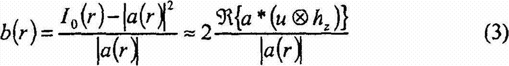

为再现u(r)给出合理的基础。Give a reasonable basis for reproducing u(r).
方程式(3)的分析能够通过假设参考场a(r)=1而简化。但是,在我们的申请中,照明激光捕获光束40,在到达焦平面前通过非均匀样品。任何产生的振幅变化,能够通过用|a(r)|使I(r)归一化而消除。照明相位中的结构,不能以此方式补偿,而必须假设该结构比任何感兴趣的特征的变化更为平缓。The analysis of equation (3) can be simplified by assuming the reference field a(r)=1. However, in our application, the illuminating laser captures the beam 40, which passes through the non-homogeneous sample before reaching the focal plane. Any resulting amplitude variation can be removed by normalizing I(r) by |a(r)|. Structure in the illumination phase cannot be compensated for in this way, but must be assumed to vary more gradually than any feature of interest.
再现三维强度场,最容易是用Fourier卷积定理实施,按照该定理Reproduce the three-dimensional intensity field, the easiest is to use the Fourier convolution theorem, according to the theorem
这里U(q)是u(r,0)的Fourier变换,而Here U(q) is the Fourier transform of u(r,0), and
是瑞利-索莫菲传播函数的Fourier变换。is the Fourier transform of the Rayleigh-Sommerphy propagation function.
对在焦平面上方高度z′处的物体场的Fourier变换的估算,是通过应用适当的瑞利-索莫菲传播函数,使有效的焦平面平移而获得的:An estimate of the Fourier transform of the object field at a height z' above the focal plane is obtained by translating the effective focal plane by applying the appropriate Rayleigh-Sommerphy propagation function:
B(q)H-z′(q)≈U(q)Hz-z′(q)+U·(q)H-z-z′(q) (8)B(q)H -z′ (q)≈U(q)H zz′ (q)+U·(q)H -zz′ (q) (8)
方程式(8)中第一项是再现场,当z′=z时,该再现场变成最佳聚焦。第二项是赝像,该赝像随z′的增加而逐渐模糊。遗憾的是,该项产生围绕z=0平面的镜像,导致焦平面以下的物体不能与焦平面以上的物体区分。这种重影出现在图2E中。The first term in equation (8) is the re-site, which becomes the best focus when z'=z. The second term is the artifact, which gradually blurs as z' increases. Unfortunately, this term produces a mirror image around the z=0 plane, causing objects below the focal plane to be indistinguishable from objects above the focal plane. This ghosting appears in Figure 2E.
我们对在焦平面上方高度z处的复光场的最后估算是Our final estimate of the complex optical field at height z above the focal plane is
方程式(9)能够从单幅全息瞬态图I(r),再现受检查样品中的即时光场的体积表示。图2E中的该像,就是通过被再现的强度分布|υ(r,z)|2的断面。Equation (9) enables the reconstruction of the volumetric representation of the instantaneous light field in the sample under examination from a single holographic snapshot I(r). The image in Fig. 2E is the section through the reconstructed intensity distribution |υ(r, z)| 2 .
图2E中每一个球,作为集中于相对暗的波纹上亮的轴向条纹,出现在物体的三维位置上。叠加在图2E上的圆圈,标明球70的预定三维位置,这些圆圈被用来计算排列球70的阱形成的全息图。在得到的再现场中,光陷阱的设计和特征之间非常良好的符合,证明该投射和成像方法两者的精度。Each sphere in Figure 2E appears as bright axial stripes centered on relatively dark corrugations at the three-dimensional position of the object. The circles superimposed on FIG. 2E, indicating the predetermined three-dimensional positions of the balls 70, are used to calculate the hologram formed by the wells of the arrayed balls 70. In the resulting re-scene, there is a very good agreement between the design and characteristics of the light traps, demonstrating the precision of both the projection and imaging methods.
与现有技术中以前的报告相反,诸如图3A到3F中的那些像指出,我们的全息再现的轴向分辨率,接近衍射受限的平面内分辨率。图3A表明的全息图,是对焦平面上方高度z=17μm处的被光镊子夹持的球70之一获得的。图3B是通过从
有效的轴向分辨率,能够通过扫描越过焦平面的球并堆叠得到的像来建立体积数据集合而评定。图3C是来自图3A在z=0处同一球的全息图。沿轴向步长Δz=0.122μm汇集一系列这样的像,得到图3D中的轴向断面。Effective axial resolution can be assessed by scanning the sphere across the focal plane and stacking the resulting images to create a volume data set. Figure 3C is a hologram of the same sphere at z=0 from Figure 3A. A series of such images were assembled along the axial step size Δz = 0.122 μm to obtain the axial section in Fig. 3D.
能够分析在球的像中沿轴方向的结构,以便沿z以及沿x和y跟踪球70。例如,对这里研究的微米尺度的粒子或球70,质心被定位在沿散射图形轴的下游强度极大和上游强度极小之间的零点平面中。因此,胶体粒子的全息显微术,能够被用于抽取三维轨迹,它比用常规两维成像所能做到的更精确,而且远比用扫描三维成像技术快速。尤其是,平面内跟踪能够使用常规技术,而沿深度方向跟踪则要求另外的计算却没有另外的校准。Structures along the axis in the image of the ball can be analyzed to track the ball 70 along z as well as along x and y. For example, for the micron-scale particles or spheres 70 studied here, the center of mass is positioned in the zero plane between the downstream intensity maximum and the upstream intensity minimum along the axis of the scattering pattern. Thus, holographic microscopy of colloidal particles can be used to extract 3D trajectories more accurately than can be done with conventional 2D imaging, and far faster than with scanning 3D imaging techniques. In particular, in-plane tracking can use conventional techniques, whereas depth-wise tracking requires additional calculations without additional calibration.
当物体沿光轴相互遮挡,如图4A和4B所示时,分析像变得更具挑战性。这里,与图2A-2E相同的球70的图形,已被转过90°,于是,4个球70沿光轴80排成一列。图4A是得到的全息图的细节,而图4B是沿该结构的竖直平面的全息再现。从图4B中央观察,所有4个球70已被分辨,哪怕它们相互直接遮挡。第5个球70,没有被其他球直接遮挡,包含在图中作为参考,且在图4A和4B中在其他球的右侧可以看到。Analyzing images becomes more challenging when objects occlude each other along the optical axis, as shown in Figures 4A and 4B. Here, the same pattern of balls 70 as in Figs. 2A-2E has been rotated by 90° so that four balls 70 are aligned along the optical axis 80. Figure 4A is a detail of the resulting hologram, while Figure 4B is a holographic reconstruction along the vertical plane of the structure. Viewed from the center of Figure 4B, all four balls 70 have been resolved even though they directly occlude each other. A fifth ball 70, not directly occluded by the other balls, is included in the figure for reference and is visible to the right of the other balls in FIGS. 4A and 4B.
图4B最上面的球70,看似比更接近焦平面被捕获的那些球显著更暗;而图4A和4B通过给出光场的振幅|υ(r,z)|而不是强度,对此作了补偿。但是,参考球70不比它邻近的被遮挡的球更亮,也不比图2A-2E中任一球70更暗。说得更确切些,更下面的球70起透镜的作用,收集从上面散射的光,并把光会聚到光轴80。结果是,这些球70看似比正常的显著更亮,且它们的像发生畸变。方程式(9)在再现光场时,没有考虑这种多重光散射。The uppermost sphere 70 of Fig. 4B appears to be significantly dimmer than those trapped closer to the focal plane; while Figs. 4A and 4B illustrate this by giving the amplitude |υ(r,z)| rather than the intensity of the light field compensation. However, the reference sphere 70 is no brighter than its adjacent occluded spheres, nor is it darker than any of the spheres 70 in FIGS. 2A-2E. More precisely, the lower ball 70 acts as a lens, collecting light scattered from above and converging it onto the optical axis 80 . As a result, these balls 70 appear to be significantly brighter than normal and their images are distorted. Equation (9) does not take this multiple light scattering into account when reproducing the light field.
在解释这样的结果时得到的不确定性,能够通过从多个焦平面采集像,或通过从多个角度照亮被研究的样品,而不是直接的同轴照明,可以缓解该不确定性。还可以通过更精确的记录,改善所得到的结果。我们的全息像中每一像素,包含约6比特有用的信息,并且没有企图对摄像机的响应进行线性化。摄像机60设在1/2000秒的快门速度,无论如何,在每次曝光中,这样的速度允许某个粒子的运动。更宽的动态范围、校准的强度响应、和更快的快门,所有这些将给出更清晰的、更精确的全息图,从而给出更清楚的三维再现。The resulting uncertainty in interpreting such results can be mitigated by acquiring images from multiple focal planes, or by illuminating the sample under study from multiple angles rather than direct on-axis illumination. The results obtained can also be improved through more accurate recording. Each pixel in our hologram contains about 6 bits of useful information, and there is no attempt to linearize the camera's response. The camera 60 is set at a shutter speed of 1/2000 second, however this speed allows for some particle motion in each exposure. Wider dynamic range, calibrated intensity response, and faster shutter, all of which will give sharper, more precise holograms and thus clearer three-dimensional reproductions.
基于这些告诫,图4B的像突显用于三维全息处理的全息成像的潜在重要性。即使最远距离的粒子70和参考粒子两者,都被定位在投射到相同高度的光镊子中,但最远距离的粒子70看似沿光轴相对于参考粒子位移。三维可视性证实被投射的捕获场的结构。对倾斜小于约80°,表观上的轴向位移是不明显的。由此,表观轴向位移,要么反映三维成像的赝像,要么最可能是粒子70离开它们的设计配置的真实位移。这是合理的,因为从被投射到更靠近焦平面的阱来的光,对更深入样品中的被捕获粒子施加力。这种效应由于更靠近焦平面的被捕获粒子而变得更严重,这些粒子把光偏折到更远的粒子上,改变它们有效的势能阱。这种效应已经被用在沿线状Bessel光束捕获的粒子的同轴光学结合中。全息成像为测量这种畸变提供一种手段,从而为改正这种畸变提供基础。这对诸如光子异质结构的全息组合的处理过程,至关重要,光子异质结构的全息组合,有赖于对这种粒子或物体的显微镜的准确放置。With these caveats, the image of Figure 4B highlights the potential importance of holographic imaging for three-dimensional holographic processing. Even though both the most distant particle 70 and the reference particle are positioned in the optical tweezers projected to the same height, the most distant particle 70 appears to be displaced relative to the reference particle along the optical axis. Three-dimensional visualization confirms the structure of the projected capture field. For tilts less than about 80°, the apparent axial displacement is insignificant. Thus, the apparent axial displacement either reflects an artifact of the three-dimensional imaging, or most likely is the true displacement of the particles 70 from their designed configuration. This is reasonable because light from the trap projected closer to the focal plane exerts a force on the trapped particles deeper into the sample. This effect is exacerbated by trapped particles closer to the focal plane, which deflect light onto farther particles, changing their effective potential energy wells. This effect has been exploited in coaxial optical binding of particles trapped along a linear Bessel beam. Holographic imaging provides a means to measure this distortion, thereby providing a basis for correcting this distortion. This is crucial for processes such as the holographic assembly of photonic heterostructures, which rely on the precise placement of such particles or objects by the microscope.
前面对本发明实施例的描述,是为演示和说明的目的而给出。不企图穷举或把本发明限制在所公开的精确形式,因为借鉴上述教导,可以进行修改和变化,或者可以从实施本发明中进行修改和变化。实施例的选取和描述,是为了解释本发明的原理和它的实际应用,以便使本领域熟练人员能在各种实施例中,并以认为适合具体应用的各种修改,利用本发明。The foregoing descriptions of embodiments of the present invention have been presented for purposes of illustration and description. It is not intended to be exhaustive or to limit the invention to the precise form disclosed, since modifications and changes are possible in light of the above teachings or may be learned from practice of the invention. The embodiments were chosen and described in order to explain the principles of the invention and its practical application, to enable others skilled in the art to utilize the invention in various embodiments and with various modifications as deemed suitable for particular applications.
Claims (40)


Applications Claiming Priority (2)
| Application Number | Priority Date | Filing Date | Title |
|---|---|---|---|
| US89778407P | 2007-01-26 | 2007-01-26 | |
| US60/897,784 | 2007-01-26 |
Related Parent Applications (1)
| Application Number | Title | Priority Date | Filing Date |
|---|---|---|---|
| CN200880003125.2A Division CN101632134A (en) | 2007-01-26 | 2008-01-25 | Holographic microscopy system and method for optical trapping and material inspection |
Publications (1)
| Publication Number | Publication Date |
|---|---|
| CN102866494A true CN102866494A (en) | 2013-01-09 |
Family
ID=39410014
Family Applications (2)
| Application Number | Title | Priority Date | Filing Date |
|---|---|---|---|
| CN2012103519707A Pending CN102866494A (en) | 2007-01-26 | 2008-01-25 | Holographic microscopy for trapping three-dimensional structure |
| CN200880003125.2A Pending CN101632134A (en) | 2007-01-26 | 2008-01-25 | Holographic microscopy system and method for optical trapping and material inspection |
Family Applications After (1)
| Application Number | Title | Priority Date | Filing Date |
|---|---|---|---|
| CN200880003125.2A Pending CN101632134A (en) | 2007-01-26 | 2008-01-25 | Holographic microscopy system and method for optical trapping and material inspection |
Country Status (5)
| Country | Link |
|---|---|
| US (1) | US7839551B2 (en) |
| EP (2) | EP2106611B1 (en) |
| JP (1) | JP5514553B2 (en) |
| CN (2) | CN102866494A (en) |
| WO (1) | WO2008092107A1 (en) |
Cited By (1)
| Publication number | Priority date | Publication date | Assignee | Title |
|---|---|---|---|---|
| US12535769B2 (en) | 2020-07-12 | 2026-01-27 | Orbotech Ltd. | Systems and methods for reconstruction of digital holograms |
Families Citing this family (49)
| Publication number | Priority date | Publication date | Assignee | Title |
|---|---|---|---|---|
| US8149416B2 (en) * | 2005-10-17 | 2012-04-03 | Arryx, Inc. | Apparatus and method for dynamic cellular probing and diagnostics using holographic optical forcing array |
| WO2007136745A2 (en) | 2006-05-19 | 2007-11-29 | University Of Hawaii | Motion tracking system for real time adaptive imaging and spectroscopy |
| US7847238B2 (en) * | 2006-11-07 | 2010-12-07 | New York University | Holographic microfabrication and characterization system for soft matter and biological systems |
| US8791985B2 (en) | 2007-10-30 | 2014-07-29 | New York University | Tracking and characterizing particles with holographic video microscopy |
| US8049814B2 (en) | 2008-03-27 | 2011-11-01 | The Rockefeller University | Holographic microscope |
| US9846313B2 (en) | 2008-09-25 | 2017-12-19 | The Trustees Of Columbia University In The City Of New York | Devices, apparatus and method for providing photostimulation and imaging of structures |
| US9316578B2 (en) | 2008-10-30 | 2016-04-19 | New York University | Automated real-time particle characterization and three-dimensional velocimetry with holographic video microscopy |
| US8451450B2 (en) * | 2009-09-14 | 2013-05-28 | Bio-Rad Laboratories, Inc. | Near real time optical phase conjugation |
| JP5554965B2 (en) * | 2009-11-06 | 2014-07-23 | オリンパス株式会社 | Laser microscope using phase modulation spatial light modulator |
| US8711211B2 (en) * | 2010-06-14 | 2014-04-29 | Howard Hughes Medical Institute | Bessel beam plane illumination microscope |
| US10051240B2 (en) | 2010-06-14 | 2018-08-14 | Howard Hughes Medical Institute | Structured plane illumination microscopy |
| JP5444530B2 (en) * | 2010-07-07 | 2014-03-19 | 公立大学法人兵庫県立大学 | Holographic microscope, method for recording hologram image of minute object, method for producing hologram for reproducing high resolution image, and method for reproducing image |
| CN102147539B (en) * | 2011-03-30 | 2012-06-27 | 中山大学 | Method for generating one-dimensional periodic structure light field based on pure-phase type liquid crystal spatial light modulator |
| US9606209B2 (en) | 2011-08-26 | 2017-03-28 | Kineticor, Inc. | Methods, systems, and devices for intra-scan motion correction |
| US9147102B2 (en) * | 2012-01-02 | 2015-09-29 | Camtek Ltd. | Method and system for measuring bumps based on phase and amplitude information |
| RU2496165C1 (en) * | 2012-02-21 | 2013-10-20 | Объединенный Институт Ядерных Исследований | Cryogenic hopper of balls for cold neutron moderator |
| US10327708B2 (en) | 2013-01-24 | 2019-06-25 | Kineticor, Inc. | Systems, devices, and methods for tracking and compensating for patient motion during a medical imaging scan |
| US9305365B2 (en) | 2013-01-24 | 2016-04-05 | Kineticor, Inc. | Systems, devices, and methods for tracking moving targets |
| US9717461B2 (en) | 2013-01-24 | 2017-08-01 | Kineticor, Inc. | Systems, devices, and methods for tracking and compensating for patient motion during a medical imaging scan |
| EP2950714A4 (en) | 2013-02-01 | 2017-08-16 | Kineticor, Inc. | Motion tracking system for real time adaptive motion compensation in biomedical imaging |
| US20140235948A1 (en) * | 2013-02-19 | 2014-08-21 | The Board Of Trustees Of The Leland Stanford Junior University | Method for single-fiber microscopy using intensity-pattern sampling and optimization-based reconstruction |
| WO2014136784A1 (en) | 2013-03-06 | 2014-09-12 | 浜松ホトニクス株式会社 | Fluorescence detection device and fluorescence detection method |
| ES2812611T3 (en) | 2014-02-12 | 2021-03-17 | Univ New York | Rapid feature identification for holographic tracking and colloidal particle characterization |
| WO2015148391A1 (en) | 2014-03-24 | 2015-10-01 | Thomas Michael Ernst | Systems, methods, and devices for removing prospective motion correction from medical imaging scans |
| US10156522B2 (en) * | 2014-04-17 | 2018-12-18 | The Regents Of The University Of California | Parallel acquisition of spectral signals from a 2-D laser beam array |
| CN104090364B (en) * | 2014-05-16 | 2016-03-02 | 北京理工大学 | A kind of method that far field full vector calculates |
| CN104001692B (en) * | 2014-05-16 | 2016-03-02 | 中南大学 | A kind of device and method based on holographic optical tweezer principle cleaning material |
| EP3188660A4 (en) | 2014-07-23 | 2018-05-16 | Kineticor, Inc. | Systems, devices, and methods for tracking and compensating for patient motion during a medical imaging scan |
| WO2016077472A1 (en) | 2014-11-12 | 2016-05-19 | New York University | Colloidal fingerprints for soft materials using total holographic characterization |
| KR101703543B1 (en) * | 2015-04-23 | 2017-02-07 | 연세대학교 산학협력단 | Multi Mode Stimulated Emission Depletion Microscope System Combined with Digital Holography Method |
| WO2016178856A1 (en) | 2015-05-01 | 2016-11-10 | The Board Of Regents Of The University Of Texas System | Uniform and scalable light-sheets generated by extended focusing |
| US9943247B2 (en) | 2015-07-28 | 2018-04-17 | The University Of Hawai'i | Systems, devices, and methods for detecting false movements for motion correction during a medical imaging scan |
| WO2017048960A1 (en) | 2015-09-18 | 2017-03-23 | New York University | Holographic detection and characterization of large impurity particles in precision slurries |
| CN108697367A (en) | 2015-11-23 | 2018-10-23 | 凯内蒂科尓股份有限公司 | Systems, devices and methods for patient motion to be tracked and compensated during medical image scan |
| US11385157B2 (en) | 2016-02-08 | 2022-07-12 | New York University | Holographic characterization of protein aggregates |
| US10876970B2 (en) | 2016-04-12 | 2020-12-29 | The Board Of Regents Of The University Of Texas System | Light-sheet microscope with parallelized 3D image acquisition |
| US10670677B2 (en) | 2016-04-22 | 2020-06-02 | New York University | Multi-slice acceleration for magnetic resonance fingerprinting |
| CN106908946B (en) * | 2016-05-05 | 2019-03-22 | 中国计量大学 | A Simplified Dual-Beam Optical Tweezers System |
| KR101783404B1 (en) * | 2016-10-07 | 2017-10-10 | 한국과학기술원 | Dynamic holographic single atom tweezers and tweezing method using thereof |
| NL2019891B1 (en) * | 2017-11-10 | 2019-05-17 | Lumicks Tech B V | Label-free microscopy |
| US10607064B2 (en) * | 2018-05-21 | 2020-03-31 | Himax Technologies Limited | Optical projection system and optical projection method |
| WO2020091965A2 (en) | 2018-11-02 | 2020-05-07 | Hologic, Inc. | Digital imaging system and method |
| US20230003632A1 (en) * | 2019-09-20 | 2023-01-05 | Kansas State University Research Foundation | Methods and apparatus for contactless orthographic imaging of aerosol particles |
| US11543338B2 (en) | 2019-10-25 | 2023-01-03 | New York University | Holographic characterization of irregular particles |
| US11948302B2 (en) | 2020-03-09 | 2024-04-02 | New York University | Automated holographic video microscopy assay |
| CN112067532B (en) * | 2020-04-29 | 2021-12-28 | 天津农学院 | A Composite Digital Holographic Microscopy Method for Measuring the Optical Axial Position of the Three-dimensional Displacement of Particles |
| US12174585B2 (en) * | 2020-06-19 | 2024-12-24 | New York University | System and method for real-time in-situ holographic microscopy |
| CN111816343B (en) * | 2020-07-01 | 2022-07-19 | 浙江大学 | Method and device for realizing multi-position optical trap by utilizing sinusoidal phase modulation |
| WO2025110049A1 (en) * | 2023-11-22 | 2025-05-30 | 国立大学法人広島大学 | Selective irradiation control device, selective irradiation control method, program, and selective irradiation system |
Citations (2)
| Publication number | Priority date | Publication date | Assignee | Title |
|---|---|---|---|---|
| CN1685773A (en) * | 2002-08-01 | 2005-10-19 | 芝加哥大学 | Apparatus and methods for fabricating, screening and fusing materials with holographic optical traps |
| CN1886684A (en) * | 2003-10-28 | 2006-12-27 | 阿而利克斯公司 | Systems and methods for manipulating and manipulating materials using holographic optical trapping |
Family Cites Families (13)
| Publication number | Priority date | Publication date | Assignee | Title |
|---|---|---|---|---|
| US6055106A (en) * | 1998-02-03 | 2000-04-25 | Arch Development Corporation | Apparatus for applying optical gradient forces |
| US7133203B2 (en) * | 1998-02-03 | 2006-11-07 | Arch Development Corporation | Apparatus for applying optical gradient forces |
| TW531661B (en) * | 2000-10-06 | 2003-05-11 | Arch Dev Corp | Method of controllably filling an array of small particles, method of controllably manipulating an array of optical traps, and apparatus for controllably manipulating an array of optical traps |
| CA2724743C (en) * | 2001-06-29 | 2014-11-25 | Universite Libre De Bruxelles | Method and device for obtaining a sample with three-dimensional microscopy |
| US20030021016A1 (en) * | 2001-07-27 | 2003-01-30 | Grier David G. | Parallel scanned laser confocal microscope |
| EP3252538B1 (en) * | 2001-12-04 | 2019-02-06 | Ecole Polytechnique Federale De Lausanne (Epfl) | Apparatus and method for digital holographic imaging |
| JP2004325944A (en) * | 2003-04-25 | 2004-11-18 | Canon Inc | Micro object processing equipment |
| CA2525843A1 (en) * | 2003-05-16 | 2004-12-02 | University Of Chicago | Optical fractionation methods and apparatus |
| JPWO2005004151A1 (en) | 2003-07-07 | 2006-08-17 | パイオニア株式会社 | Information recording medium, recording apparatus and recording method for information recording medium, reproducing apparatus and reproducing method for information recording medium, computer program for recording or reproduction control, and data structure including control signal |
| JP2005337730A (en) * | 2004-05-24 | 2005-12-08 | Nara Institute Of Science & Technology | Measuring system |
| WO2006058187A2 (en) * | 2004-11-23 | 2006-06-01 | Robert Eric Betzig | Optical lattice microscopy |
| US7473890B2 (en) * | 2004-11-23 | 2009-01-06 | New York University | Manipulation of objects in potential energy landscapes |
| WO2007008921A2 (en) * | 2005-07-12 | 2007-01-18 | Arryx, Inc. | Method and apparatus for forming multi-dimensional colloidal structures using holographic optical tweezers |
-
2008
- 2008-01-25 CN CN2012103519707A patent/CN102866494A/en active Pending
- 2008-01-25 WO PCT/US2008/052098 patent/WO2008092107A1/en not_active Ceased
- 2008-01-25 JP JP2009547444A patent/JP5514553B2/en not_active Expired - Fee Related
- 2008-01-25 EP EP08728321A patent/EP2106611B1/en not_active Not-in-force
- 2008-01-25 US US12/020,376 patent/US7839551B2/en active Active
- 2008-01-25 CN CN200880003125.2A patent/CN101632134A/en active Pending
- 2008-01-25 EP EP12169084A patent/EP2492921A1/en not_active Withdrawn
Patent Citations (2)
| Publication number | Priority date | Publication date | Assignee | Title |
|---|---|---|---|---|
| CN1685773A (en) * | 2002-08-01 | 2005-10-19 | 芝加哥大学 | Apparatus and methods for fabricating, screening and fusing materials with holographic optical traps |
| CN1886684A (en) * | 2003-10-28 | 2006-12-27 | 阿而利克斯公司 | Systems and methods for manipulating and manipulating materials using holographic optical trapping |
Non-Patent Citations (1)
| Title |
|---|
| KEIR C.NEUMAN ET AL: "Optical trapping", 《REVIEW OF SCIENTIFIC INSTRUMENTS》 * |
Cited By (1)
| Publication number | Priority date | Publication date | Assignee | Title |
|---|---|---|---|---|
| US12535769B2 (en) | 2020-07-12 | 2026-01-27 | Orbotech Ltd. | Systems and methods for reconstruction of digital holograms |
Also Published As
| Publication number | Publication date |
|---|---|
| EP2106611A1 (en) | 2009-10-07 |
| US7839551B2 (en) | 2010-11-23 |
| WO2008092107B1 (en) | 2008-11-06 |
| EP2106611B1 (en) | 2013-01-23 |
| JP2010517102A (en) | 2010-05-20 |
| WO2008092107A1 (en) | 2008-07-31 |
| JP5514553B2 (en) | 2014-06-04 |
| CN101632134A (en) | 2010-01-20 |
| US20090027747A1 (en) | 2009-01-29 |
| EP2492921A1 (en) | 2012-08-29 |
Similar Documents
| Publication | Publication Date | Title |
|---|---|---|
| CN102866494A (en) | Holographic microscopy for trapping three-dimensional structure | |
| US8331019B2 (en) | Holographic microscopy of holographically trapped three-dimensional nanorod structures | |
| TWI797377B (en) | Surface shape measuring device and surface shape measuring method | |
| JP5170084B2 (en) | 3D microscope and 3D image acquisition method | |
| JP4772961B2 (en) | Method for simultaneously forming an amplitude contrast image and a quantitative phase contrast image by numerically reconstructing a digital hologram | |
| US11644791B2 (en) | Holographic imaging device and data processing method therefor | |
| US10073025B2 (en) | Method and device for incoherent imaging with coherent diffractive reconstruction | |
| US10156829B2 (en) | Holographic microscope and data processing method for high-resolution hologram image | |
| CN114324245A (en) | Apparatus and method for quantitative phase microscopy based on partially coherent structured light illumination | |
| Abbasian et al. | Microsphere-assisted quantitative phase microscopy: a review | |
| CN115096857A (en) | A kind of OCT imaging method and device based on Airy light sheet line scanning | |
| WO2021172135A1 (en) | Phase imaging device and phase imaging method | |
| Arcab et al. | Single-shot experimental-numerical twin-image removal in lensless digital holographic microscopy | |
| KR102272366B1 (en) | Method and apparatus for the phase retrieval and volumetric imaging reconstruction | |
| Jiang et al. | Phase retrieval of on-axis digital holography with modified coherent diffraction imaging | |
| Almoro et al. | Object wave reconstruction by speckle illumination and phase retrieval | |
| Dong et al. | Single-shot high-throughput phase imaging with multibeam array interferometric microscopy | |
| HK1138677A (en) | Holographic microscope system and method for optical trapping and inspection of materials | |
| Wang et al. | Perfect digital holographic imaging with high resolution using a submillimeter-dimension CCD sensor | |
| JP2019179233A (en) | Light wave measurement device and light wave measurement method | |
| Yamamoto et al. | 3D particle measurements by single beam two-views magnified digital in-line holography | |
| Lebrun et al. | A new method for recording single-shot two-scales in-line holograms: Application to the visualization of a stretched viscoelastic fluid | |
| Subedi | Characterization of microparticles through digital holography | |
| Běhal et al. | Lateral shearing digital holographic microscopy with incoherent illumination | |
| KR20240041450A (en) | optical diffraction tomographic apparatus based on multiple objective lens |
Legal Events
| Date | Code | Title | Description |
|---|---|---|---|
| C06 | Publication | ||
| PB01 | Publication | ||
| C10 | Entry into substantive examination | ||
| SE01 | Entry into force of request for substantive examination | ||
| C02 | Deemed withdrawal of patent application after publication (patent law 2001) | ||
| WD01 | Invention patent application deemed withdrawn after publication |
Application publication date: 20130109 |