CN102834981A - Female terminal - Google Patents
Female terminal Download PDFInfo
- Publication number
- CN102834981A CN102834981A CN2011800169955A CN201180016995A CN102834981A CN 102834981 A CN102834981 A CN 102834981A CN 2011800169955 A CN2011800169955 A CN 2011800169955A CN 201180016995 A CN201180016995 A CN 201180016995A CN 102834981 A CN102834981 A CN 102834981A
- Authority
- CN
- China
- Prior art keywords
- convex portion
- lead plate
- contact portion
- protrusions
- elastic contact
- Prior art date
- Legal status (The legal status is an assumption and is not a legal conclusion. Google has not performed a legal analysis and makes no representation as to the accuracy of the status listed.)
- Granted
Links
Images


Classifications
-
- H—ELECTRICITY
- H01—ELECTRIC ELEMENTS
- H01R—ELECTRICALLY-CONDUCTIVE CONNECTIONS; STRUCTURAL ASSOCIATIONS OF A PLURALITY OF MUTUALLY-INSULATED ELECTRICAL CONNECTING ELEMENTS; COUPLING DEVICES; CURRENT COLLECTORS
- H01R13/00—Details of coupling devices of the kinds covered by groups H01R12/70 or H01R24/00 - H01R33/00
- H01R13/02—Contact members
- H01R13/10—Sockets for co-operation with pins or blades
- H01R13/11—Resilient sockets
- H01R13/113—Resilient sockets co-operating with pins or blades having a rectangular transverse section
Landscapes
- Connections Effected By Soldering, Adhesion, Or Permanent Deformation (AREA)
- Connector Housings Or Holding Contact Members (AREA)
- Coupling Device And Connection With Printed Circuit (AREA)
Abstract
本发明目的在于提供既能抑制雄型端子的插入引板插入嵌合结构的插入力的增大又能可靠地导电的雌型端子。该雌型端子(1)具备允许雄型端子中的插入引板(300)插入的盒部(2),在盒部(2)中具备与所插入的插入引板(300)弹性接触的弹性接触片(21)、与弹性接触片相对并通过与弹性接触片共同夹持所插入的插入引板来嵌合插入引板(300)的内侧顶部(22b),在内侧顶部(22b)上形成有朝着弹性接触片(21)突出的半球状凸部(81),相对于后方半球状凸部(81a)将前方半球状凸部(81b)配置在与插入引板(300)的插入方向(X)交叉的位置,且将在两端形成有半球状凸部(81)的斜焊缝(80)以在内侧顶部(22b)的面内与宽窄方向(Y)交叉的方式配置。
The purpose of this invention is to provide a female terminal that can both suppress the increase of insertion force in the insertion mating structure of the male terminal's insertion lead plate and reliably conduct electricity. The female terminal (1) has a housing (2) that allows the insertion lead plate (300) of the male terminal to be inserted. The housing (2) has an elastic contact piece (21) that elastically contacts the inserted insertion lead plate (300), and an inner top (22b) that is opposite to the elastic contact piece and clamps the inserted insertion lead plate together with the elastic contact piece to fit the insertion lead plate (300). A hemispherical protrusion (81) protruding toward the elastic contact piece (21) is formed on the inner top (22b). The front hemispherical protrusion (81b) is positioned at a position that intersects the insertion direction (X) of the insertion lead plate (300) with respect to the rear hemispherical protrusion (81a). The oblique weld (80) with hemispherical protrusions (81) formed at both ends is arranged in a manner that intersects the width direction (Y) in the plane of the inner top (22b).
Description
技术领域 technical field
本发明涉及安装于连接器等的雌型端子,例如上述连接器被用于负责车辆用线束的连接。The present invention relates to a female terminal mounted on a connector or the like, which is used, for example, for connection of a wiring harness for a vehicle.
背景技术 Background technique
以往,在车辆中配置有很多线束,这些线束利用连接器连接。在这样的连接器中内置有压接端子,所述压接端子对应于构成线束的被覆电线中每一个进行压接固定。Conventionally, many wire harnesses are arranged in a vehicle, and these wire harnesses are connected by connectors. Such a connector incorporates a crimping terminal that is crimped and fixed corresponding to each of the covered electric wires constituting the wire harness.
像这样的压接端子为具备平板状的插入引板的雄型端子和具备允许所示插入引板插入的盒部的雌型端子成为一对所构成,所述雄型端子和所述雌型端子分别以连接于被覆电线的状态安装在连接器内部。Such a crimping terminal is constituted by a pair of a male terminal provided with a flat plate-shaped insertion lead plate and a female terminal provided with a box portion allowing the insertion lead plate to be inserted as shown. The terminals are mounted inside the connector in a state of being connected to the covered electric wires, respectively.
另外,雌型端子的盒部是如下结构:与所插入的插入引板弹性接触的弹性接触部和与该弹性接触部相对的固定接触部,由弹性接触部和固定接触部夹持所插入的插入引板,从而将插入引板电连接且物理连接来进行嵌合。In addition, the box part of the female terminal has the following structure: the elastic contact part in elastic contact with the inserted lead plate and the fixed contact part opposite to the elastic contact part, and the inserted contact part is clamped by the elastic contact part and the fixed contact part. The insertion leads are fitted by electrically and physically connecting the insertion leads.
近年来,伴随着车辆中的电路构成的复杂化等,连接器中的端子数存在增多的倾向。端子数这样增加时,内置有上述那样的端子的连接器彼此的嵌合连接需要较大的插入力。由此,为了使连接器的嵌合作业容易化,强烈地期望使雄型端子插入雌型端子的插入力降低。In recent years, the number of terminals in the connector tends to increase along with the complexity of the circuit configuration in the vehicle. When the number of terminals increases in this way, a large insertion force is required for the fitting connection between the connectors incorporating the above-mentioned terminals. Therefore, in order to facilitate the fitting operation of the connector, it is strongly desired to reduce the insertion force for inserting the male terminal into the female terminal.
不过,重视连接器嵌合作业的容易化而谋求接触载荷的降低时,存在导致嵌合状态下的连接可靠性降低这样的问题。详细而言,接触载荷较低时,由于端子表面的氧化、微滑动摩擦的发生、热或者振动等的影响,而引起两端子的接触电阻的增大、通电状态瞬间被切断这样的事态。However, when emphasis is placed on simplification of the connector fitting work and reduction of the contact load is achieved, there is a problem that the connection reliability in the mated state is reduced. Specifically, when the contact load is low, oxidation of the terminal surface, generation of micro-sliding friction, influence of heat or vibration, etc., cause the contact resistance of both terminals to increase and the energized state to be interrupted instantaneously.
针对这样的问题提出有使形成在弹性接触部上的凸起多点化的雌型端子(专利文献1)。In response to such a problem, a female terminal in which the protrusions formed on the elastic contact portion are multi-pointed has been proposed (Patent Document 1).
该雌型端子是如下结构:弹性接触部与固定接触部一起夹持被插入盒部的插入引板来进行嵌合,形成于弹性接触部的作为凸起的凸部在宽窄方向的不同的位置具备多个,并且,形成于固定接触部的作为焊缝(bead)的凸部在宽窄方向的不同的位置具备多个。This female terminal has a structure in which the elastic contact portion and the fixed contact portion pinch and fit the insertion lead plate inserted into the box portion, and the convex portion as a protrusion formed on the elastic contact portion is at different positions in the width direction. A plurality of protrusions are provided, and a plurality of protrusions serving as beads formed on the fixed contact portion are provided at different positions in the width direction.
采用该结构的专利文献1的雌型端子由于盒部所具备的多个凸部,所插入的插入引板难以旋转,耐振动特性提高。因而,不需要使弹性接触部的弹簧性能提高而使凸部和插入引板之间的接触载荷增大,不使插入引板插入雌型端子的盒部的插入力增大就能够实现可靠的嵌合状态。In the female terminal of
不过,现今的车辆要求伴随着节能化的轻量化,与线束的细线化一起进行端子的小型化。这样,进行端子的小型化时,如现有文献1那样,在宽窄方向的不同的位置形成多个凸部在空间上存在困难。However, today's vehicles are required to reduce the size of the terminal along with the reduction in weight of the wire harness along with energy saving. Thus, when miniaturizing the terminal, it is difficult in terms of space to form a plurality of protrusions at different positions in the width direction as in
此外,即使是在宽窄方向的不同的位置能够形成多个凸部的情况下,将确保与车辆中的电路构成的复杂化、高电流化等相对应的接触面积的凸部全部配置在宽窄方向的不同的位置是困难的。因此,需要在插入引板插入雌型端子的盒部的方向上的不同的位置配置凸部。In addition, even if a plurality of protrusions can be formed at different positions in the width direction, all the protrusions that ensure a contact area corresponding to the complexity of the circuit configuration in the vehicle, the increase in current, etc. are arranged in the width direction. The different positions are difficult. Therefore, it is necessary to arrange the protrusions at different positions in the direction in which the insertion lead plate is inserted into the box portion of the female terminal.
不过,在仅沿着插入方向配置了凸部的情况下、插入方向前侧的凸部在插入引板上的插入方向后侧的凸部已滑动的部位滑动。这样,存在如下问题:使凸部在其另一凸部已滑动的部位进一步滑动时,插入引板中的凸部的滑动阻力增加,因此,插入力变高。However, when the convex portion is arranged only along the insertion direction, the convex portion on the front side in the insertion direction slides on the insertion lead plate where the convex portion on the rear side in the insertion direction has slid. In this way, there is a problem that when the convex portion is further slid at a position where the other convex portion has already slid, the sliding resistance of the convex portion inserted into the lead plate increases, so that the insertion force becomes high.
现有技术文献prior art literature
专利文献patent documents
专利文献1:日本特开2009-37741号公报Patent Document 1: Japanese Unexamined Patent Publication No. 2009-37741
发明内容Contents of the invention
本发明所要解决的技术问题Technical problem to be solved by the present invention
本发明的目的在于提供一边能够抑制雄型端子的插入引板插入嵌合结构的插入力的增大一边能够可靠地导电的雌型端子。An object of the present invention is to provide a female terminal capable of reliably conducting electricity while suppressing an increase in insertion force of an insertion tab insertion fitting structure of a male terminal.
解决所述问题的技术方案Technical solution to solve the problem
本发明的雌型端子,该雌型端子具备允许雄型端子中的插入引板插入的嵌合结构,其特征在于,所述嵌合结构具备弹性接触部和相对接触部,所述弹性接触部与被插入所述嵌合结构的所述插入引板弹性接触、所述相对接触部与该弹性接触部相对并与所述弹性接触部共同夹持所插入的所述插入引板以进行嵌合,在该相对接触部上形成有两个以上的凸部,该凸部朝向所述弹性接触部侧突出,相对于所述两个以上的凸部中的一个凸部将另一个凸部配置在与所述插入引板插入所述嵌合结构的方向交叉的位置,并且,在将所述凸部中的两个凸部作为凸部组时,至少一个凸部组配置成在所述相对接触部的面内在与所述插入方向正交的宽窄方向上交叉。In the female terminal of the present invention, the female terminal has a fitting structure that allows the insertion lead plate in the male terminal to be inserted, and it is characterized in that the fitting structure has an elastic contact portion and an opposing contact portion, and the elastic contact portion elastically contacting the insertion lead plate inserted into the fitting structure, the opposing contact portion is opposite to the elastic contact portion and clamps the inserted insertion lead plate together with the elastic contact portion for fitting , two or more protrusions are formed on the opposing contact portion, and the protrusions protrude toward the elastic contact portion side, and one of the two or more protrusions is disposed on the other side. The position intersects with the direction in which the insertion guide plate is inserted into the fitting structure, and when two of the protrusions are used as a protrusion group, at least one protrusion group is configured to be in the relative contact The planes of the parts intersect in the width direction perpendicular to the insertion direction.
所述嵌合结构是被称为所谓的盒部,该嵌合结构允许雄型端子的插入引板插入,并能够进行电连接和物理连接的用于嵌合的结构。此外,具备嵌合结构的所述雌型端子能够为具备将构成线束的被覆电线露出的露出电线部分和压接覆盖部分的压接部的压接端子。另外,压接部也可以是开放压接形式或者封闭压接形式等中的任一种形式的压接部,还可以例如是用超声波焊接等电连接且物理连接的结构。The said fitting structure is what is called a box part, and this fitting structure allows the insertion lead plate of a male terminal to be inserted, and is the structure for fitting which can make electrical connection and physical connection. In addition, the female terminal having a fitting structure may be a crimping terminal having an exposed wire portion exposing a covered wire constituting the wire harness and a crimping portion for crimping the covered portion. In addition, the crimping portion may be of any type such as an open crimping type or a closed crimping type, and may also be electrically and physically connected by, for example, ultrasonic welding.
所述相对接触部能够形成为雌型端子的盒部等的嵌合结构中的一部分的固定部分、固定部分所具备的可动部分。The opposing contact portion can be formed as a part of a fixed portion in a fitting structure such as a box portion of a female terminal, or as a movable portion included in the fixed portion.
所述凸部能够形成为如称为焊缝的大致半圆截面棒状、大致矩形截面棒状那样形成在沿着插入方向具有长度的形状的一部的凸部、分别独立地形成的凸部。The protrusion can be formed as a protrusion formed in a part of a shape having a length along the insertion direction, such as a substantially semicircular cross-sectional rod shape called a weld, or a substantially rectangular cross-sectional rod shape, or a protrusion formed independently.
相对于所述两个以上的凸部中一个凸部将另一凸部配置在与所述插入引板插入所述嵌合结构的方向交叉的位置是指,配置在将两个的凸部的中心在相对接触部上连结的方向线与插入方向交叉的位置。With respect to one of the two or more protrusions, disposing the other protrusion at a position intersecting with the direction in which the insertion guide plate is inserted into the fitting structure means that the two protrusions are arranged at a position between two protrusions. The position where the direction line connecting the center on the opposing contact portion intersects the insertion direction.
在将所述凸部中的两个凸部作为凸部组时,至少一个凸部组配置成在所述相对接触部面的内在与所述插入方向正交的宽窄方向上交叉是指,例如在具有3个凸部的情况下,能够构成3个凸部组,其中一个凸部组的配置方向与宽窄方向交叉,因此,3个凸部中的至少两个凸部在插入方向上配置在不同的位置。When two of the protrusions are used as a protrusion group, at least one protrusion group is arranged to intersect in the width direction perpendicular to the insertion direction in the surface of the opposing contact portion means, for example, In the case of three protrusions, three protrusion groups can be formed, and the arrangement direction of one protrusion group intersects with the width direction. Therefore, at least two of the three protrusions are arranged in the direction of insertion. different locations.
因而,相对于两个以上的凸部中的一个凸部将另一凸部配置在与所述插入引板插入所述嵌合结构的方向交叉的位置,并且,将所述凸部中的两个凸部作为凸部组时,至少一个凸部组配置成在所述相对接触部的面内在与所述插入方向正交的宽窄方向上交叉的情况能够形成为:例如配置在相对于插入方向倾斜的方向上的两个凸部、或者,配置成插入方向上的V字状、倒V字状或者配置成宽窄方向上的へ字状的3个凸部、还能够形成为配置成插入方向的斜体N字状、ハ字状、或者倒ハ字状的4个凸部。Therefore, with respect to one of the two or more protrusions, the other protrusion is arranged at a position intersecting the direction in which the insertion tab is inserted into the fitting structure, and two of the protrusions are arranged When two convex portions are used as the convex portion group, at least one convex portion group is arranged so as to intersect in the width direction perpendicular to the insertion direction in the plane of the opposing contact portion. Two protrusions in the inclined direction, or three protrusions arranged in a V-shape, an inverted V-shape in the insertion direction, or a へ-shape in the width direction can also be formed so that they are arranged in the insertion direction The italic N-shaped, ハ-shaped, or inverted ハ-shaped 4 convex parts.
采用本发明,能够一边抑制雄型端子的插入引板插入嵌合结构的插入力的增大一边可靠地导电。According to the present invention, it is possible to reliably conduct electricity while suppressing an increase in the insertion force of the insertion tab insertion fitting structure of the male terminal.
详细而言,将两个以上的凸部形成于相对接触部,用相对接触部和弹性接触部夹持插入引板来进行嵌合,因此,能够确保接触面积,实现可靠的导电性。Specifically, two or more protrusions are formed on the opposing contact portion, and the insertion lead plate is sandwiched and fitted between the opposing contact portion and the elastic contact portion. Therefore, the contact area can be ensured and reliable electrical conductivity can be realized.
此外,相对于两个以上的凸部中的一个凸部将另一凸部配置在与所述插入引板插入所述嵌合结构的方向交叉的位置,并且,在将所述凸部中的两个凸部作为凸部组时,至少一个凸部组配置成在所述相对接触部的面内在与所述插入方向正交的宽窄方向上交叉,因此,配置在插入方向的不同的位置的凸部的宽窄方向位置也不同,插入方向前侧的凸部在与插入方向的后侧的凸部在插入引板上滑动的部位不同的、插入引板中的平滑的未滑动部位进行滑动。因而,与通过在已滑动的部位进一步滑动来增大滑动阻力的情况相比,能够防止插入力的增加。In addition, with respect to one of the two or more protrusions, the other protrusion is arranged at a position intersecting with the direction in which the insertion tab is inserted into the fitting structure, and, in placing one of the protrusions When two convex portions are used as a convex portion group, at least one convex portion group is arranged so as to intersect in the width direction perpendicular to the insertion direction in the plane of the opposing contact portion, and therefore, the convex portion groups arranged at different positions in the insertion direction The positions of the protrusions in the width direction are also different, and the protrusions on the front side in the insertion direction slide on a smooth non-sliding position in the insertion guide plate that is different from the position where the protrusions on the rear side in the insertion direction slide on the insertion guide plate. Therefore, it is possible to prevent an increase in the insertion force compared to the case where the sliding resistance is increased by further sliding the already slid site.
采用这样的上述构成,插入力不增加,因此,能够最大限度地很大地设计接触载荷,例如能够构成向对于因车辆行驶中的振动的微滑动摩耗也具有优异性能的雌型端子。由此,即使是伴随电路构成的复杂化等而增加了端子数的连接器,也能够可靠地将两端子嵌合连接,确保稳定的连接状态。With such a configuration, the insertion force does not increase, so the contact load can be designed to be as large as possible, for example, a female terminal having excellent performance against micro-sliding friction due to vibration during running of the vehicle can be configured. Thereby, even in a connector whose number of terminals increases due to the complication of the circuit configuration, etc., both terminals can be reliably fitted and connected, and a stable connection state can be ensured.
作为本发明的方式,能够将所述宽窄方向中的各凸部的位置即宽窄方向位置设定成,各凸部中的宽窄方向中心彼此间的宽窄方向间隔为所述凸部和所述插入引板所接触的接触宽度的一半以上。As an aspect of the present invention, the position of each protrusion in the width direction, that is, the position in the width direction can be set such that the distance in the width direction between the width centers of each protrusion is equal to the distance between the protrusion and the insertion. More than half of the contact width that the lead plate is in contact with.
所述宽窄方向中心能够为凸部中的宽窄方向的最外两侧的中心。The center in the width direction may be the center of the outermost sides in the width direction of the protrusion.
所述宽窄方向中心彼此的宽窄方向间隔能够为各凸部的宽窄方向中心彼此间的宽窄方向上的距离。The distance in the width direction between the centers in the width direction can be the distance in the width direction between the centers in the width direction of the protrusions.
采用本发明,各凸部滑动的部位的轨迹在宽窄方向错开,因此,即使是在插入方向上配置在不同的位置的凸部,通过在另一凸部已滑动的部位再次滑动,从而能够防止产生插入力增加这样的不良情况。According to the present invention, the track of the sliding part of each convex part is staggered in the width direction. Therefore, even if the convex part is arranged at a different position in the insertion direction, it can be prevented by sliding again at the part where another convex part has slid. There occurs a disadvantage that the insertion force increases.
详细而言,各凸部的宽窄方向位置设为宽窄方向间隔为接触宽度的一半以下的情况下,插入方向前侧的凸部的轨迹和插入方向后侧的凸部的轨迹重合一半以上。Specifically, when the widthwise position of each protrusion is such that the widthwise interval is less than half of the contact width, the trajectory of the protrusion on the front side in the insertion direction and the trajectory of the protrusion on the rear side in the insertion direction overlap by more than half.
这样,插入方向后侧的凸部与已滑动的部位重合,插入方向前侧的凸部再次滑动,从而插入力增加。并且,在宽窄方向间隔为接触宽度的一半以下这样窄的情况下,插入方向前侧的凸部被向插入方向后侧的凸部已滑动的部位引导,因此,滑动阻力增加,插入力提高。In this way, the convex portion on the rear side in the insertion direction overlaps with the slid portion, and the convex portion on the front side in the insertion direction slides again, thereby increasing the insertion force. In addition, when the interval in the width direction is as narrow as half or less of the contact width, the protrusion on the front side in the insertion direction is guided to the position where the protrusion on the rear side in the insertion direction has slid, so the sliding resistance increases and the insertion force increases.
不过,以宽窄方向中心彼此间的宽窄方向间隔为接触宽度的一半以上的方式设定凸部的宽窄方向位置,各凸部的轨迹在宽窄方向错开,能够防止滑动阻力增大所导致的插入力的增加。However, by setting the widthwise positions of the protrusions so that the widthwise interval between the widthwise centers is at least half of the contact width, the trajectory of each protrusion is shifted in the widthwise direction, and insertion force due to increased sliding resistance can be prevented. increase.
此外,作为本发明的方式,在所述相对接触部上具备突出部,该突出部在与所述插入方向交叉的方向上形成地较长,且朝向所述弹性接触部侧突出,并且,所述突出部至少在中间部具有规定长度的凹部,所述凹部能够构成在所述突出部上中的所述凹部的两外侧。Furthermore, as an aspect of the present invention, the opposing contact portion is provided with a protruding portion formed long in a direction intersecting with the insertion direction and protruding toward the elastic contact portion side, and the The protruding portion has a concave portion of a predetermined length at least in the middle portion, and the concave portion can constitute both outer sides of the concave portion on the protruding portion.
采用本发明,通过形成突出部,由此,能够在形成于中间部分的凹部的两侧形成凸部,能够形成形状稳定性较高的凸部。According to the present invention, by forming the protruding portion, the convex portion can be formed on both sides of the concave portion formed in the middle portion, and the convex portion with high shape stability can be formed.
详细而言,在形成于中间部分的凹部的两侧形成的凸部与突出部一体地形成,因此,与在被小型化的雌型端子的相对接触部上分别形成独立的凸部的情况相比,能够可靠地形成强度高、具有例如用于与插入引板可靠地接触的的高度的凸部。因而,能够确保可靠的导电性能。In detail, the protrusions formed on both sides of the recess formed in the middle portion are integrally formed with the protrusions, and thus are different from the case where independent protrusions are formed on the opposing contact portions of the miniaturized female terminal. Compared with this, it is possible to reliably form a high-strength convex portion having, for example, a height for reliably contacting an insertion lead plate. Thus, reliable electrical conductivity can be ensured.
此外,作为本发明的方式,能够形成为如下结构:所述相对接触部包括具有与所述弹性接触部方向相对的的弹性的弹性相对接触部,所述弹性接触部和所述弹性相对接触部对所插入的所述插入引板施加沿着彼此相对的方向的力的同时夹持所插入的所述插入引板来进行嵌合。Furthermore, as an aspect of the present invention, it is possible to have a configuration in which the opposing contact portion includes an elastic opposing contact portion having elasticity opposite to the direction of the elastic contact portion, and the elastic contact portion and the elastic opposing contact portion Fitting is performed by pinching the inserted insertion lead plates while applying a force in a direction facing each other to the inserted insertion lead plates.
所述弹性相对接触部为与弹性接触部相同的构造,能够形成为相对于所插入的插入引板对称配置的接触部。The elastic opposing contact portion has the same structure as the elastic contact portion, and can be formed as a contact portion symmetrically arranged with respect to the inserted insertion tab.
采用本发明,弹性接触部和弹性相对接触部对所插入的插入引板一边向彼此相对的方向施力一边夹持所插入的插入引板来进行嵌合,因此,除了上述的效果之外,能够确保更可靠的导电性能。此外,用弹性接触部和弹性相对接触部一边向彼此相对的方向施力一边进行夹持来进行嵌合,因此能够以所期望的作用力施力来进行嵌合。According to the present invention, the elastic contact portion and the elastic opposing contact portion clamp and fit the inserted insertion tab while biasing the inserted insertion tab in a direction facing each other. Therefore, in addition to the above-mentioned effects, More reliable electrical conductivity can be ensured. In addition, since the elastic contact portion and the elastic opposing contact portion are clamped and fitted while being biased in directions facing each other, the fitting can be biased with a desired urging force.
此外,作为本发明的方式,能够具备相对于所具备的多个所述凸部中的半数以下的所述凸部配置在所述插入引板的所述插入方向上的前侧位置的前位置凸部。In addition, as an aspect of the present invention, it is possible to provide a front position in which half or less of the plurality of protrusions provided is located at a position on the front side in the insertion direction of the insertion tab. Convex.
上述前位置凸部能够是与上述凸部相同的形状的凸部、或者不同形状的凸部。The said front position convex part can be a convex part of the same shape as the said convex part, or a convex part of a different shape.
此外,相对于上述凸部配置在所述插入引板的所述插入方向上的前侧位置的前位置凸部能够为相对于凸部配置在宽窄方向位置一致的前侧位置的前位置凸部、或者配置在凸部中的宽窄方向中心彼此间的宽窄方向间隔为所述凸部与所述插入引板所接触的接触宽度的一半以下的前侧位置的前位置凸部,或者配置在前侧位置的前位置凸部。In addition, the front position convex portion arranged at the front side position in the insertion direction of the insertion tab with respect to the above-mentioned convex portion may be a front position convex portion arranged at a front side position at the same position in the width direction relative to the convex portion. , or arranged in the front position convex part at the front position where the distance between the centers in the width direction of the convex part is less than half of the contact width between the convex part and the insertion lead plate, or arranged in the front The front position convex part of the side position.
采用本发明,能够一边具有雄型端子的插入引板插入嵌合结构的插入力的增大抑制效果一边提高凸部的配置的自由度。According to the present invention, it is possible to increase the degree of freedom in the arrangement of the protrusions while having an effect of suppressing an increase in the insertion force of the insertion tab insertion fitting structure of the male terminal.
详细而言,例如即使是为了增大需要通电量而需要进一步增加接触面积的情况,将前位置凸部相对于所具备的多个所述凸部中的半数以下的所述凸部配置在所述插入引板的所述插入方向上的前侧位置,从而一边能够最低限度地确保配置在与插入引板插入所述嵌合结构的方向交叉的位置的两个以上的凸部的插入力的增大抑制效果,一边利用配置的自由度较高的前位置凸部增大接触面积。In detail, for example, even if it is necessary to further increase the contact area in order to increase the required amount of current flow, the front position convex portion is arranged on all the convex portions that are not more than half of the plurality of convex portions provided. The position on the front side of the insertion direction of the insertion guide plate can be ensured at a minimum while ensuring the insertion force of the two or more protrusions arranged at positions intersecting with the direction in which the insertion guide plate is inserted into the fitting structure. The suppressing effect is increased, and the contact area is increased by the front position convex part with a high degree of freedom of arrangement.
此外,作为本发明的方式,能够具备配置在与所插入的所述插入引板的顶端附近接触的顶端位置,且相对于所述凸部沿着所述插入方向上配置的顶端位置凸部。Furthermore, as an aspect of the present invention, a distal position convex portion disposed in contact with the vicinity of the distal end of the inserted insertion tab and disposed along the insertion direction with respect to the convex portion may be provided.
上述顶端位置凸部能够为与上述凸部相同形状的凸部,或者不同形状的凸部。The above-mentioned tip position convex portion may be a convex portion having the same shape as the above-mentioned convex portion, or a convex portion having a different shape.
此外,相对于上述的凸部配置在所述插入引板的所述插入方向上的顶端位置的顶端位置凸部能够为相对于凸部配置在宽窄方向位置一致的顶端位置的顶端位置凸部、或者配置在凸部中的宽窄方向中心彼此间的宽窄方向间隔为所述凸部与所述插入引板所接触的接触宽度的一半以下的顶端位置的顶端位置凸部、或者、配置在顶端位置的顶端位置凸部。In addition, the distal position convex portion arranged at the distal position of the insertion tab in the insertion direction with respect to the above-mentioned convex portion can be a distal position convex portion arranged at a distal position at the same position in the width direction relative to the convex portion, Or the convex part is arranged at the top position of the top position where the widthwise interval between the widthwise centers of the convex part is less than half of the contact width between the convex part and the insertion lead plate, or arranged at the top position The top position of the convex part.
采用本发明,能够一边具有雄型端子的插入引板插入嵌合结构的插入力的增大抑制效果一边提高凸部的配置的自由度。According to the present invention, it is possible to increase the degree of freedom in the arrangement of the protrusions while having an effect of suppressing an increase in the insertion force of the insertion tab insertion fitting structure of the male terminal.
详细而言,例如即使是为了增大必要通电量而需要进一步增加接触面积的情况,在所述插入引板的所述插入方向的顶端位置,将顶端位置凸部沿着相对于凸部的插入方向配置,从而一边能够最低限度地确保配置在与插入引板插入所述嵌合结构的方向交叉的位置的两个以上的凸部的插入力的增大抑制效果,一边利用配置的自由度较高的顶端位置凸部增大接触面积。Specifically, for example, even if it is necessary to further increase the contact area in order to increase the necessary current flow, at the tip position of the insertion lead plate in the insertion direction, the tip position convex portion is inserted along the insertion direction relative to the convex portion. direction, so that while ensuring the effect of suppressing the increase in the insertion force of two or more protrusions arranged at a position intersecting with the direction in which the insertion tab is inserted into the fitting structure at a minimum, the degree of freedom of arrangement is utilized. The high top position protrusion increases the contact area.
此外,本发明的连接构造体,其特征在于,上述的雌型端子由压接部和所述嵌合结构构成,该压接部对从用绝缘性的覆盖体覆盖电线导体的外周而成的被覆电线中的自所述覆盖体的顶端露出规定长度的所述电线导体的露出部分进行压接,该连接构造体是利用所述压接部将所述被覆电线和所述雌型端子连接而成的。In addition, the connection structure of the present invention is characterized in that the above-mentioned female terminal is composed of a crimping portion and the fitting structure, and the crimping portion is formed by covering the outer periphery of the wire conductor with an insulating covering. In the covered electric wire, the exposed portion of the electric wire conductor exposed for a predetermined length from the top end of the covering body is crimped. In this connection structure, the covered electric wire and the female terminal are connected by the crimping portion. into.
采用本发明,雄型端子中的插入引板能够容易地插入,以实现可靠且稳定的电连接。With the present invention, the insertion lead plate in the male terminal can be easily inserted to realize reliable and stable electrical connection.
并且,此外,本发明的连接器,其特征在于,该连接器是将上述连接构造体中的雌型端子至少一个配置在连接器外壳内而构成的。Furthermore, the connector of the present invention is characterized in that the connector is configured by arranging at least one of the female terminals in the connection structure in the connector housing.
将上述的雌型端子至少一个配置在连接器外壳内而成的连接器是包含下述的概念:将安装于连接器的多个的雌型端子中的全部形成为上述连接构造体中的雌型端子、将多个的雌型端子中的一部分形成为上述连接构造体中的雌型端子、或者、将上述连接构造体中的雌型端子仅一个安装在连接器中。The connector in which at least one of the above-mentioned female terminals is arranged in the connector housing includes the following concept: all of the plurality of female terminals mounted on the connector are formed as female terminals in the above-mentioned connection structure. type terminals, forming some of the plurality of female terminals as female terminals in the connection structure, or mounting only one female terminal in the connection structure in the connector.
采用本发明,能够将压接端子和电线导体构成确保了稳定的导电性的嵌合状态。According to the present invention, the crimp terminal and the electric wire conductor can be made into a fitted state in which stable electrical conductivity is ensured.
发明效果Invention effect
采用本发明,能够提供一边抑制雄型端子的插入引板向嵌合结构插入的插入力的增大一边能够可靠地导电的雌型端子。According to the present invention, it is possible to provide a female terminal capable of reliably conducting electricity while suppressing an increase in the insertion force of the insertion lead plate of the male terminal into the fitting structure.
附图说明 Description of drawings
图1是雌型端子的说明图。FIG. 1 is an explanatory diagram of a female terminal.
图2是雌型端子的说明图。Fig. 2 is an explanatory diagram of a female terminal.
图3是焊缝的轨迹的说明图。FIG. 3 is an explanatory diagram of a trajectory of a weld.
图4是焊缝的宽窄方向位置的轨迹的说明图。FIG. 4 is an explanatory diagram of the locus of the position in the widthwise direction of the weld bead.
图5是焊缝图案的说明图。FIG. 5 is an explanatory diagram of a weld pattern.
图6是独立焊缝图案的说明图。Fig. 6 is an explanatory diagram of an independent bead pattern.
图7是另一焊缝的说明图。Fig. 7 is an explanatory view of another weld.
图8是两层弹性接触片类型的雌型端子的纵剖视图。Fig. 8 is a longitudinal sectional view of a two-layer elastic contact piece type female terminal.
图9是前位置凸部的说明图。Fig. 9 is an explanatory diagram of a front position protrusion.
图10是顶端凸部的说明图。FIG. 10 is an explanatory diagram of a tip convex portion.
图11是连接器的说明立体图。Fig. 11 is an explanatory perspective view of the connector.
具体实施方式 Detailed ways
下面基于附图说明本发明的一种实施方式。One embodiment of the present invention will be described below based on the drawings.
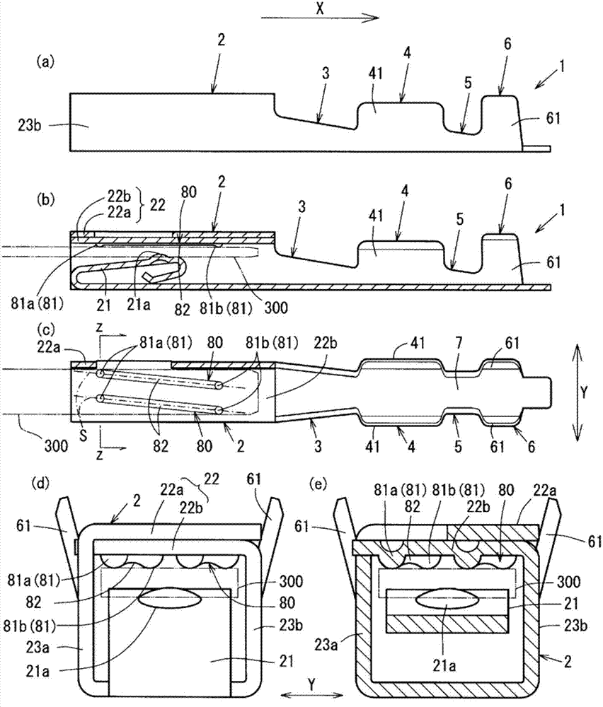
另外,图1和图2表示雄型压接端子1的说明图。在此,图1中的(a)表示在宽窄方向Y的中央分断的雌型压接端子1的截面立体图,图1中的(b)表示组装途中状态的雌型压接端子1的立体图,图1中的(c)表示将被覆电线200压接于芯线压接部4的状态的雌型压接端子1的立体图。In addition, FIGS. 1 and 2 show explanatory views of the
此外,图2中的(a)表示雌型压接端子1的侧面图,图2中的(b)表示宽窄方向Y的中央位置的雌型压接端子1的剖视图,图2中的(c)表示图1中的(b)所示的组装前状态的雌型压接端子1的俯视图。并且,图2中的(d)表示雌型压接端子1的主视图,图2中的(e)表示图2中的(c)中所示的z-z截面中的从正面侧看的剖视图。In addition, (a) in FIG. 2 shows a side view of the
图3表示斜焊缝80的轨迹的说明图,图4表示斜焊缝80的宽窄方向位置的轨迹的说明图。另外,图3中的(a)表示直行焊缝180和斜焊缝80的各自轨迹的概略图,图3中的(b)表示各自的静摩擦力的比较图表。FIG. 3 is an explanatory diagram showing the locus of the
此外,图4中的(a)和(b)表示斜焊缝80的宽窄方向位置的轨迹的概略图,图4中的(c)表示直行焊缝180的轨迹的概略图,图4中的(d)表示半球状凸部81和插入引板300的接触宽度a的概略图。In addition, (a) and (b) in FIG. 4 show the schematic diagram of the locus of the width direction position of the
图5表示斜焊缝80的焊缝图案的局部俯视图和主视图的说明图,图6表示独立半球状凸部91(独立平凸部93)的焊缝图案的局部俯视图和主视图的说明图。FIG. 5 shows an explanatory diagram of a partial top view and a front view of a weld pattern of an
首先,说明雌型压接端子1。雌型压接端子1将盒部2、芯线压接部4、绝缘体压接部6一体地构成,该盒部2允许雄型连接器400b(参照图11)中的雄型压接端子(省略图示)的插入引板从插入方向X的后方朝向前方插入,该芯线压接部4在盒部2的前方,借助规定长度的第1过渡3配置,该绝缘体压接部6在芯线压接部4的前方,借助规定长度的第2过渡5配置。另外,插入方向X是指插入引板300(图2)插入盒部2的插入方向,是与雌型压接端子1的长度方向一致的方向。First, the
压接连接于雌型压接端子1的被覆电线200是用由绝缘树脂构成的绝缘覆盖201覆盖将铜电线成束而成的芯线202而构成的。The covered
雌型压接端子1是对表面被以大约0.001mm的厚度镀锡(镀Sn)的、大约0.2mm的厚度的黄铜等铜合金条实施形状加工和弯曲加工而立体构成的开放压接型端子。The female crimping
另外,表面被实施的镀Sn是为了提高焊锡的焊接性和插入引板300插入时的滑动性而实施的。此外,雌型压接端子1不限定于开放压接形式,也可以是封闭压接形式。In addition, the Sn plating on the surface is performed to improve the solderability of the solder and the slidability when the
并且,对被覆电线200的芯线202和雌型压接端子1进行例如超声波焊接那样的焊接,由此,也可以是电连接且物理连接的结构。此外,雌型压接端子1也可以是对铝合金条实施加工而立体构成的压接端子。Further, the core wire 202 of the covered
如图1中的(b)所示,压接前的芯线压接部4具备芯线压接片41,该芯线压接片41从压接底部7的宽窄方向Y的两侧向外侧斜上方延伸,侧视看来呈长方形,压接前的芯线压接部4从前方看来形成为大致U型。As shown in (b) of FIG. 1 , the core
此外,压接前的绝缘体压接部6也具备绝缘体压接片61,该绝缘体压接片61从压接底部7的宽窄方向Y的两侧向外侧斜上方延伸,压接前的绝缘体压接部6从前方看来形成为大致U型。In addition, the
这样构成的芯线压接部4对被覆电线200的芯线202进行凿紧来压接,绝缘体压接部6对被覆电线200的绝缘覆盖201进行凿紧来压接,从而能够将雌型压接端子1和被覆电线200电连接且物理连接。The core
盒部2由放倒的中空四棱柱体构成,且内部具备弹性接触片21,该弹性接触片21朝着插入方向X的前方弯曲,且具有与所插入的雄型压接端子的插入引板300(参照图2)接触的凸起21a。The
中空四棱柱体的盒部2的顶部22(22a、22b)通过将侧面部分23(23a、23b)的延长部分重叠的方式弯曲而构成。The top part 22 (22a, 22b) of the
详细而言,将正面视右侧的右侧面23b的延长部分即上半部分沿着左侧面23a的方向以大致直角弯曲从而构成内侧顶部22b,以重叠于该内侧顶部22b上侧的方式将左侧面23a的延长部分即上半部分向右侧面23b侧以大致直角弯曲从而构成外侧顶部22a,由该外侧顶部22a和内侧顶部22b构成顶部22。Specifically, the upper half, which is an extension of the
并且,在内侧顶部22b形成有在宽窄方向Y上的平行的两根斜焊缝80。In addition, two parallel
斜焊缝80沿着插入方向X形成得较长,沿着与插入方向X交叉的方向配置,在该插入方向X的两端形成有半球状凸部81。The oblique welds 80 are formed to be long along the insertion direction X, are arranged along a direction intersecting the insertion direction X, and have
详细而言,如图1中的(b)所示,斜焊缝80是在弯曲状态的内侧顶部22b中以向弹性接触片21侧突出的方式形成的半圆截面棒状,将其中间部分向上方向凹而形成中间凹部82。并且,使该中间凹部82的两端部分以半球状向下方突出而形成半球状凸部81。In detail, as shown in (b) of FIG. 1 , the
并且,两根斜焊缝80以各半球状凸部81的宽窄方向位置不重叠的方式配置在与插入方向X交叉的方向和位置。In addition, the two
另外,上述宽窄方向位置是指内侧顶部22b中的半球状凸部81在宽窄方向Y上的位置。In addition, the said width direction position is the position of the hemispherical
此外,以大约0.1mm以上的半径形成半球状凸部81,以0.01mm以上且内侧顶部22b的厚度以下的尺寸凹而形成中间凹部82。In addition, the hemispherical
并且,如图2中的(d)和(e)所示,以各半球状凸部81的宽窄方向位置不重叠的方式配置的两根斜焊缝80在与插入方向X呈5度向正面视右侧交叉的配置方向S配置。下面对该配置方向S详细论述。Furthermore, as shown in (d) and (e) in FIG. Arrange according to the arrangement direction S of the cross on the right side. The arrangement direction S will be discussed in detail below.
如图4中的(a)所示,将连结插入方向X的后方即后方半球状凸部81a的中心与插入方向X的前方即前方半球状凸部81b的中心的配置方向S与插入方向X的交叉角度设为θ,将后方半球状凸部81a和前方半球状凸部81b的中心距设为焊缝长b。As shown in (a) in FIG. The intersecting angle of θ is θ, and the center-to-center distance between the rear hemispherical
此外,如图4中的(d)所示,将半球状凸部81与插入引板300接触的接触部分在宽窄方向Y上的宽度设为接触宽度a。In addition, as shown in (d) of FIG. 4 , the width in the width direction Y of the contact portion where the hemispherical
因而,后方半球状凸部81a与前方半球状凸部81b的宽窄方向间隔c用焊缝长b和交叉角度θ表示时,c=b×Sinθ。Therefore, when the distance c in the widthwise direction between the rear hemispherical
在此,如图4中的(a)所示,若宽窄方向间隔c为接触宽度a以上,则后方半球状凸部81a相对于插入引板300的滑动轨迹R1与前方半球状凸部81b的滑动轨迹R2在宽窄方向Y上不重叠,在滑动轨迹R1和滑动轨迹R2形成不同轨道间隔T1。Here, as shown in (a) of FIG. 4 , if the gap c in the width direction is equal to or greater than the contact width a, the rear hemispherical
相对于此,如图4中的(b)所示,若宽窄方向间隔c短于接触宽度a且为接触宽度a的一半以上,则后方半球状凸部81a的滑动轨迹R1与前方半球状凸部81b的滑动轨迹R2在宽窄方向Y上重叠,形成宽度为接触宽度a的一半以下的轨道重复部T2。On the other hand, as shown in (b) of FIG. 4 , if the interval c in the width direction is shorter than the contact width a and is more than half of the contact width a, the sliding trajectory R1 of the rear hemispherical
另外,在上述的说明中,半球状凸部81滑动而形成的滑动轨迹R(R1、R2)是形成在从盒部2的正面侧插入的插入引板300上的轨迹。并且,插入方向X的后方即后方半球状凸部81a比前方半球状凸部81b先与插入引板300接触而滑动,插入引板300插入到前方半球状凸部81b位置后,前方半球状凸部81b开始在插入引板300上滑动。In addition, in the above description, the sliding trajectory R ( R1 , R2 ) formed by sliding the hemispherical
此外,被实施在插入引板300和半球状凸部81的表面的镀Sn由于插入引板300和半球状凸部81之间的滑动而变形或者剥离,使得滑动轨迹R中的半球状凸部81和插入引板300之间的滑动性降低。In addition, the Sn plating applied on the surface of the
并且,关于半球状凸部81的宽窄方向间隔c,不仅相同的斜焊缝80上的后方半球状凸部81a和前方半球状凸部81b的宽窄方向位置,而且不同的斜焊缝80的后方半球状凸部81a和前方半球状凸部81b的宽窄方向位置也需要同样的范围。In addition, regarding the widthwise distance c of the
这样,在上述范围内使后方半球状凸部81a和前方半球状凸部81b的宽窄方向位置错开地配置斜焊缝80,从而能够降低插入引板300插入盒部2的插入力。详细而言,如以示意图表示的图3中的(a)所示,在平行于插入方向X的直行焊缝180的情况下,通过插入引板300的插入,直行焊缝180相对于插入引板300产生从初始位置A到移动后位置B的相对移动,直行焊缝180的前方半球状凸部181b在后方半球状凸部181a滑动而成的滑动轨迹R’上移动。Thus, by arranging the
这样,前方半球状凸部181b在后方半球状凸部181a的滑动轨迹R’上移动,因此,半球状凸部181和插入引板300之间的移动性越发降低,提高插入引板300插入盒部2的插入力。In this way, the front hemispherical
相对于此,在沿着与插入方向X交叉的配置方向S配置的斜焊缝80的情况下,斜焊缝80相对于插入引板300产生从初始位置A到移动后位置B的相对移动,斜焊缝80的前方半球状凸部81b未在后方半球状凸部81a的移动轨迹R1上移动,因此,半球状凸部81和插入引板300之间的移动性不会降低,插入引板300插入盒部2的插入力不变化。On the other hand, in the case of the
例如,在本实施例中,如使用1根焊缝的模拟样品而测量的图3中的(b)所示,相对于插入力为3.6N的直行焊缝180(在图表中用0度表示),斜焊缝80(在图表中用10度表示)为2.9N,大概使插入力、即摩擦力能够降低大约20%。For example, in this embodiment, as shown in (b) in FIG. 3 measured using a simulated sample of one weld, relative to a straight weld 180 with an insertion force of 3.6 N (indicated by 0 degrees in the graph ), the oblique weld 80 (indicated by 10 degrees in the chart) is 2.9N, which probably reduces the insertion force, that is, the friction force by about 20%.
另外,在此,将角度θ设定为10度来实施,即使是设定为5度的情况下,如上所述,若焊缝长为3mm、接触径为0.14mm,则成为不同轨道,因此,认为:角度θ为5度、10度时,没有实质的差异。In addition, here, the angle θ is set to 10 degrees and implemented. Even if it is set to 5 degrees, as described above, if the weld bead length is 3mm and the contact diameter is 0.14mm, it will become a different track. Therefore, , it is believed that there is no substantial difference when the angle θ is 5 degrees and 10 degrees.
此外,将不具备斜焊缝80中的半球状凸部81和中间凹部82的通常的半圆截面棒状的焊缝仅相对于插入方向X倾斜地配置的情况下,与插入方向X正交的宽窄方向Y中的滑动宽度变宽,因此,与具备半球状凸部81和中间凹部82的斜焊缝80相比,插入力增大是显而易见的。In addition, when a normal semicircular cross-section rod-shaped weld bead not having the hemispherical
另外,如上所述,斜焊缝80形成为半圆截面棒状,并且,在中间部分形成中间凹部82,在中间凹部82的两侧具备半球状凸部81,如图5中的(a)所示,也可以呈大致平板状向下方突出,在斜焊缝80的中间部分形成中间凹部82,在中间凹部82的两侧形成平凸部83。In addition, as described above, the
此外,在上述的说明中,将沿着与插入方向X交叉的配置方向S配置的相同方向的两根斜焊缝80平行配置,但也可以将斜焊缝80相对于插入方向X配置成ハ字状(图5中的(b))、或者倒ハ字状(图5中的(c))。并且,若满足插入引板300和雌型压接端子1之间的需要的导电性能,则也可以由1根斜焊缝80构成(图5中的(d))。另外,ハ字状、倒ハ字状或者1根斜焊缝80也形成为图5中的(a)所示那样的大致平板状,也可以构成平凸部83。In addition, in the above description, the two
此外,在半圆截面棒状或者大致平板状的斜焊缝80中的中间凹部82的两侧形成有半球状凸部81或平凸部83,如图6所示,也可以形成分别独立的独立半球状凸部91或独立平凸部93。In addition, a hemispherical
例如,如图6中的(a)所示,在与形成有上述斜焊缝80(参照图2)的半球状凸部81的相同的位置形成有独立半球状凸部91(独立平凸部93)。当然,同样,也可以在与如图5中的(b)~(d)所示配置的斜焊缝80的半球状凸部81相同的位置形成独立半球状凸部91。For example, as shown in (a) of FIG. 6 , an independent hemispherical convex portion 91 (independent flat convex portion 93). Of course, similarly, the independent hemispherical
另外,独立半球状凸部91也与半球状凸部81同样地以大致0.1mm以上的半径形成即可。In addition, the independent hemispherical
此外,如图6中的(b)所示,也可以相对于插入方向X将独立半球状凸部91(独立平凸部93)配置成倒V字状,并且,如图6中的(c)所示,也可以相对于插入方向X将独立半球状凸部91(独立平凸部93)配置成V字状。Moreover, as shown in (b) in FIG. ), the independent hemispherical convex portion 91 (independent flat convex portion 93 ) may be arranged in a V shape with respect to the insertion direction X.
并且,如图6中的(d)所示,也可以相对于宽窄方向Y将独立半球状凸部91(独立平凸部93)配置成へ字状。In addition, as shown in (d) of FIG. 6 , the independent hemispherical convex portion 91 (independent flat convex portion 93 ) may be arranged in an “へ” shape with respect to the width direction Y.
这样,斜焊缝80和独立半球状凸部91(独立平凸部93)的配置图案可以是各种图案,但至少在宽窄方向Y上相邻的半球状凸部81(平凸部83)或者独立半球状凸部91(独立平凸部93)的宽窄方向间隔c为半球状凸部81(平凸部83)或独立半球状凸部91(独立平凸部93)与插入引板300接触的接触宽度a的一半以上,从而与如直行焊缝180那样沿着插入方向X的半球状凸部181的配置相比,能够获得插入力的降低效果。In this way, the arrangement pattern of the
接着,对由于这样的斜焊缝80、独立半球状凸部91(独立平凸部93)而产生插入引板300的插入力的降低效果进行有关的效果确认试验的结果进行说明。Next, the result of an effect confirmation test on the effect of reducing the insertion force of the
另外,在该效果确认试验中,对于斜焊缝80的配置图案(焊缝配置类型),如图1和图2所示,将两根斜焊缝80平行地配置的图案作为配置类型A,将相对于插入方向X配置成ハ字状的图案(图5中的(b))作为配置类型B,将相对于插入方向X配置成倒ハ字状的图案(图5中的(c))作为配置类型C,将配置1根斜焊缝80的图案(图5中的(d))作为配置类型D。In addition, in this effect confirmation test, as for the arrangement pattern (weld arrangement type) of the oblique welds 80, as shown in FIGS. A pattern arranged in a ハ shape with respect to the insertion direction X ((b) in FIG. 5 ) is used as arrangement type B, and a pattern arranged in an inverted ハ shape with respect to the insertion direction X ((c) in FIG. 5 ) As arrangement type C, a pattern ((d) in FIG. 5 ) in which one
此外,对于独立半球状凸部91(独立平凸部93)的配置图案(焊缝配置类型),将3个相对于插入方向X配置倒V字状的图案(图6中的(b))作为配置类型E,将相对于插入方向X配置成V字状的图案(图6中的(c))作为配置类型F。In addition, for the arrangement pattern of the independent hemispherical convex portion 91 (independent flat convex portion 93 ) (weld arrangement type), three patterns are arranged in an inverted V shape with respect to the insertion direction X ((b) in FIG. 6 ). As the arrangement type E, a pattern arranged in a V shape with respect to the insertion direction X ((c) in FIG. 6 ) is used as the arrangement type F. FIG.
并且,将配置有两根直行焊缝180的图案作为配置类型X、在宽窄方向Y的中央配置1根直行焊缝180的图案作为配置类型Y。In addition, a pattern in which two straight welds 180 are arranged is designated as an arrangement type X, and a pattern in which one straight weld 180 is arranged in the center in the width direction Y is designated as an arrangement type Y.
首先,对于两根斜焊缝80,对于半球状凸部81和平凸部83分别比较配置图案A、B、C和直行焊缝180,并且,对于宽窄方向位置,将θ作为参数进行了试验。将其结果表示在表1中。First, for the two
【表1】【Table 1】

从该表1可知,通过以宽窄方向间隔c为接触宽度a的一半以上的方式配置,半球状凸部81和平凸部83这两者(发明例1~14)与直行焊缝180(比较例1、3)相比都能够确认插入力的降低效果。相反,宽窄方向间隔c比接触宽度a的一半小的情况下(比较例2、4)与直行焊缝180相比,确认到插入力未被降低。As can be seen from Table 1, by arranging such that the interval c in the width direction is equal to or more than half of the contact width a, both the hemispherical
接着,对半球状凸部81和平凸部83分别比较1根斜焊缝80(配置图案D)和1根直行焊缝180(配置图案Y),并且,对于宽窄方向位置,将θ作为参数进行了试验。将其结果表示在表2中。Next, one oblique weld 80 (arrangement pattern D) and one straight weld 180 (arrangement pattern Y) are compared for the hemispherical
【表2】【Table 2】
从该表2可知,通过以宽窄方向间隔c为接触宽度a的一半以上的方式配置,半球状凸部81和平凸部83这两者(发明例15~18)与直行焊缝180(比较例5、7)相比都能够确认插入力的降低效果。相反,在宽窄方向间隔c小于接触宽度a的一半的情况下(比较例6、8),与直行焊缝180相比,确认到插入力稍微降低。As can be seen from Table 2, by arranging such that the interval c in the widthwise direction is equal to or more than half of the contact width a, both the hemispherical
并且,在1根斜焊缝80(配置图案D)和1根直行焊缝180(配置图案Y)之间的比较中,对增加接触宽度a的情况分别比较,其结果表示在表3中。In addition, in the comparison between one oblique weld 80 (arrangement pattern D) and one straight weld 180 (arrangement pattern Y), the cases of increasing the contact width a were compared respectively, and the results are shown in Table 3.
【表3】【table 3】

从该表3可知,通过以宽窄方向间隔c为接触宽度a的一半以上的方式配置,能够确认半球状凸部81(发明例21、22)相对于直行焊缝180(比较例9、11)的降低效果比平凸部83(发明例19、20)相对于直行焊缝180(比较例9、11)的降低效果更高。此外,在宽窄方向间隔小于接触宽度a的一半的情况下(比较例10、12),确认到与直行焊缝180相比插入力几乎未被降低。As can be seen from Table 3, by arranging such that the interval c in the width direction is equal to or more than half of the contact width a, it can be confirmed that the hemispherical convex portion 81 (invention examples 21 and 22) is relatively large compared to the straight weld bead 180 (comparative examples 9 and 11). The reduction effect of the flat and convex portion 83 (invention examples 19 and 20) is higher than that of the straight weld 180 (comparative examples 9 and 11). In addition, in the case where the gap in the width direction was less than half of the contact width a (Comparative Examples 10 and 12), it was confirmed that the insertion force was hardly lowered compared to the straight weld 180 .
这样,通过将半球状凸部81、平凸部83的宽窄方向间隔c设定为接触宽度a的一半以上,与直行焊缝180相比,确认到插入引板300的插入力降低。Thus, it was confirmed that the insertion force of the
在具备这样的允许雄型端子中的插入引板300自嵌合入口部插入的盒部2的雌型压接端子1中,在盒部2内具备与所插入的插入引板300弹性接触的弹性接触片21、与弹性接触片21相对并且与弹性接触片21共同夹持所插入的插入引板300来进行嵌合的内侧顶部22b,在内侧顶部22b形成朝向弹性接触片21侧突出的两个以上的半球状凸部81,相对于后方半球状凸部81a将前方半球状凸部81b配置在与插入引板300插入盒部2的插入方向X交叉的位置,并且,将形成有两个半球状凸部81的斜焊缝80配置成在内侧顶部22b的面内与宽窄方向Y交叉,从而能够一边抑制雄型端子的插入引板300向插入盒部2的插入力的增大一边可靠地导电。In the female
详细而言,将两个以上的半球状凸部81形成于内侧顶部22b,用内侧顶部22b和弹性接触片21夹持插入引板300来进行嵌合,因此能够确保接触面积,实现可靠的导电性。Specifically, two or more
此外,相对于后方半球状凸部81a将前方半球状凸部81b配置在与插入引板300插入盒部2的插入方向X交叉的位置,并且,将形成有两个半球状凸部81的斜焊缝80配置成在内侧顶部22b面内在与插入方向X正交的宽窄方向Y上交叉,因此,配置在插入方向X的不同的位置的半球状凸部81的宽窄方向位置也不同。In addition, with respect to the rear hemispherical
因而,前方半球状凸部81b在与后方半球状凸部81a在插入引板300上滑动的部位不同的位于插入引板300中平滑的未滑动部位滑动。由此,与由于在已滑动的部位进一步滑动而产生滑动阻力增加的情况相比较,能够防止插入力的增加。Thus, the front hemispherical
这样,能够构成不增加插入力、能够最大限度地设计接触载荷、例如相对于因车辆行驶中的振动所产生的微滑动摩耗也具有优异性能的雌型压接端子1。In this way, it is possible to configure the
如图1中的(c)所示,这样的雌型压接端子1将被覆电线200压接于芯线压接部4而进行连接,构成压接连接构造体500a,将压接连接构造体500a的雌型压接端子1安装于雌型连接器外壳401a,由此,能够构成一边抑制插入力的增大一边具有可靠的导电性的雌型连接器400a。As shown in (c) of FIG. 1 , such a female-
另外,将被覆电线200连接于省略图示的雄型压接端子,构成压接连接构造体500b,并且,将压接连接构造体500b的雄型压接端子安装于雄型连接器外壳401b,构成雄型连接器400b。In addition, the covered
并且,如图11所示,通过使雌型连接器400a和雄型连接器400b嵌合,能够构成将连接于雌型压接端子1的被覆电线200、连接于雄型压接端子的被覆电线200a可导通地连接的连接器400。And, as shown in FIG. 11, by fitting the
另外,用上述的构成构成被安装于雌型连接器外壳401a的雌型压接端子1,因此,即使是伴随电路构成的复杂化等而端子数增加的连接器400(400a、400b),也能够一边抑制插入力的增大一边可靠地嵌合连接、确保稳定的连接状态。In addition, since the
此外,雌型连接器外壳401a中能够安装有多个雌型压接端子,即使不能够将全部的雌型压接端子作为本发明的雌型压接端子1,能够构成至少一个雌型压接端子1,从而抑制插入力的增大。In addition, a plurality of female crimp terminals can be installed in the
此外,将宽窄方向Y上的各半球状凸部81的位置即宽窄方向位置设定成各半球状凸部81中的宽窄方向中心彼此间的宽窄方向间隔c为半球状凸部81与插入引板300接触的接触宽度a的一半以上,从而各半球状凸部81滑动的部位的滑动轨迹R错开,因此,能够防止产生下面这样的不良情况:前方半球状凸部81b在后方半球状凸部81a已滑动的滑动轨迹R1上再次滑动而使插入力增加。In addition, the position of each
详细而言,在将各半球状凸部81的宽窄方向位置设定成宽窄方向间隔c为接触宽度a的一半以下的情况下,前方半球状凸部81b的滑动轨迹R2、后方半球状凸部81a的滑动轨迹R1重合一半以上。这样,前方半球状凸部81b以与后方半球状凸部81a已滑动的滑动轨迹R1重合的方式进行再次滑动,从而插入力增加。Specifically, when the widthwise position of each
并且,在宽窄方向间隔c小于接触宽度a的一半以下的情况下,前方半球状凸部81b被引导到后方半球状凸部81a已滑动的滑动轨迹R1,因此,滑动阻力增加,插入力提高。不过,以宽窄方向中心彼此间的宽窄方向间隔c为接触宽度a的一半以上的方式设定半球状凸部81的宽窄方向位置,从而各半球状凸部81的滑动轨迹R沿着宽窄方向Y错开,能够防止滑动阻力增加所导致的插入力的增加。In addition, when the gap c in the width direction is less than half of the contact width a, the front hemispherical
此外,在内侧顶部22b形成有斜焊缝80,该斜焊缝80在与插入方向X交叉的方向上形得较长,朝向弹性接触片21侧突出,并且,至少在中间部具有规定长度的中间凹部82,在斜焊缝80中的中间凹部82的两外侧构成半球状凸部81,从而能够形成形状稳定性较高的半球状凸部81。In addition, an
详细而言,形成在中间部分的中间凹部82的两侧的半球状凸部81与斜焊缝80一体地形成,因此,与在被小型化的雌型压接端子1的内侧顶部22b分别形成独立的半球状凸部81的情况相比较,能够可靠地形成强度较高且具有用于与例如插入引板300可靠地接触的高度的半球状凸部81。因而,能够确保可靠的导电性能。In detail, the
接着,将3个独立半球状凸部91配置成倒V字状的配置类型E和配置成V字状的配置类型F与在中央配置有1根直行焊缝180的配置类型Y相比较,并且以独立半球状凸部91的点间长度为参数进行了试验。其结果表示在表4中。Next, the arrangement type E in which the three independent
【表4】【Table 4】
从该表4可知,通过配置成宽窄方向间隔c为接触宽度a的一半以上,独立半球状凸部91(发明例23、24)相对于形成在内侧顶部22b的直行焊缝180(比较例9、11)能够确认插入力的降低效果。As can be seen from Table 4, by disposing the distance c in the widthwise direction at half or more of the contact width a, the independent hemispherical protrusions 91 (invention examples 23 and 24) can be compared with the straight weld 180 formed on the inner top 22b (comparative example 9). , 11) The effect of reducing the insertion force can be confirmed.
另外,在上述的说明中,半球状凸部81在斜焊缝80中的中间凹部82的两侧以0.1mm以上的半径形成为半球状,但也可以如另一斜焊缝80’的说明图即图7中的(a)所示,将半球状凸部81(平凸部83)和中间凹部82用插入方向X的平滑的曲线连续地形成。在该情况下,前方半球状凸部81b的插入方向X的后方的与中间凹部82之间的连续的部分、后方半球状凸部81a的插入方向X的后方的与内侧顶部22b连续的部分也以大致形成为0.1mm以上的半径即可。In addition, in the above description, the hemispherical
这样,通过形成斜焊缝80’,由此,除了上述的斜焊缝80的效果之外,能够防止插入盒部2的插入引板300卡在斜焊缝80’中的半球状凸部81(平凸部83)的插入方向X的后方部分而插入力增大这样的问题的发生。In this way, by forming the beveled bead 80', in addition to the above-mentioned effect of the
此外,也可以将斜焊缝80’在插入方向X上非对称地形成。详细而言,也可以前方半球状凸部81b的插入方向X的后方的与中间凹部82连续的部分、后方半球状凸部81a的插入方向X的后方的与内侧顶部22b连续的部分用半径0.1mm以上的平滑的曲线形成,前方半球状凸部81b的插入方向X的前方的与内侧顶部22b连续的部分、后方半球状凸部81a的插入方向X的前方的与中间凹部82连续的部分用半径0.1mm以下的曲线形成。由此,也能够获得与上述效果同样的效果。In addition, the oblique weld 80' may be formed asymmetrically in the insertion direction X. In detail, the portion continuous with the middle
此外,在上述的说明中,独立半球状凸部91(独立平凸部93)、具有半球状凸部81或平凸部83的斜焊缝80形成为构成盒部2的顶部22的内侧顶部22b,但也可以是在内侧顶部22b具备与弹性接触片21同样地具有弹簧特性的顶侧弹性接触片24、将独立半球状凸部91(独立平凸部93)、具有半球状凸部81或平凸部83的斜焊缝80形成在顶侧弹性接触片24的两层弹性接触片类型的雌型压接端子1(参照图8)。In addition, in the above description, the independent hemispherical convex portion 91 (independent flat convex portion 93 ), the
由此,在两层弹性接触片类型的雌型压接端子1中,利用弹性接触片21和顶侧弹性接触片24对插入盒部2的插入引板300使弹性接触片21和顶侧弹性接触片24的各自的施力沿着相对的方向起作用,能够夹持插入引板300来进行电连接且物理连接。Thus, in the female
并且,将形成在顶侧弹性接触片24的独立半球状凸部91(独立平凸部93)或者具有半球状凸部81或平凸部83的斜焊缝80配置成宽窄方向间隔c为接触宽度a的一半以上,与在顶侧弹性接触片24上形成直行焊缝180的情况相比较,能够降低插入力。下面,将在顶侧弹性接触片24上形成斜焊缝80、独立半球状凸部91(独立平凸部93)的情况的效果确认试验的结果表示在表5中。In addition, the independent hemispherical convex portion 91 (independent flat convex portion 93 ) formed on the top side
另外,在该效果确认试验中,在顶侧弹性接触片24中,以上述的配置类型D配置斜焊缝80(发明例25);将独立半球状凸部91(独立平凸部93)用上述的配置类型E,F配置(发明例26、27);以及,将直行焊缝180用上述的配置类型Y配置(比较例13、14)。In addition, in this effect confirmation test, in the top
【表5】【table 5】

从该表5可知,以斜焊缝80中的半球状凸部81、或者独立半球状凸部91(独立平凸部93)的宽窄方向间隔c为接触宽度a的一半以上的方式配置,从而斜焊缝80、独立半球状凸部91(发明例25~27)相对于形成在顶侧弹性接触片24上的直行焊缝180(比较例13、14)能够确认插入力的降低效果。As can be seen from Table 5, the
这样,即使是在顶侧弹性接触片24上形成斜焊缝80、独立半球状凸部91的情况,也通过使宽窄方向间隔c为接触宽度a的一半以上,与形成在顶侧弹性接触片24的直行焊缝180相比,能够确认插入引板300的插入力降低。In this way, even in the case where the
该两层弹性接触片类型的雌型压接端子1除了如上所述那样插入引板300的插入力的增加抑制效果之外,用相对的具有弹性接触片21方向的弹性的顶侧弹性接触片24构成,弹性接触片21和顶侧弹性接触片24对所插入的插入引板300沿着彼此相对的方向施力一边夹持该插入引板300来进行嵌合。The female
因而,弹性接触片21和顶侧弹性接触片24一边对所插入的插入引板300沿着彼此相对的方向施力一边该插入引板300来进行嵌合,能够确保更可靠的导电性能。此外,一边用弹性接触片21和顶侧弹性接触片24沿着彼此相对的方向施力一边进行夹持来进行嵌合,由此,能够以所期望的作用力施力来进行嵌合。Therefore, the
另外,除了上述的构成之外,也可以在内侧顶部22b具备相对于凸部(81,83、91、93)配置在插入方向X方向上的附加凸部,在该情况下,也能够一边最低限度地确保上述的效果,一边扩大插入引板300和雌型压接端子1之间的接触面积。详细而言,基于各自的局部俯视图和主视图的说明图即图9和图10说明作为附加凸部的前位置凸部101和顶端位置凸部102。In addition, in addition to the above-mentioned configuration, the inner
伴随着连接对象的增加,期望插入的被安装在雄型连接器400b的雄型压接端子的插入引板300和雌型压接端子1之间的电连接性的稳定,需要接触面积的增大。不过,也随着端子自身的小型化,凸部(81、83、91、93)的配置变得困难。Accompanied by the increase of connection objects, it is desired to stabilize the electrical connectivity between the
由此,也可以一边最小限度地确保如上所述那样在插入方向X的前方和后方使宽窄方向位置错开地配置凸部(81、83、91、93)所导致的插入引板300的插入力的增大抑制效果一边将前位置凸部101配置在凸部(81、83、91、93)的插入方向X上。Thereby, the insertion force of the
另外,在图9、10中,用四边形图示前位置凸部101、顶端位置凸部102,但这不过是表示前位置凸部101、顶端位置凸部102的位置,也可以用与独立半球状凸部91、独立平凸部93相同的形状构成,也可以用不同的形状形成。但是,前位置凸部101能够相对于多个凸部(81、83、91、93)中的半数以下的凸部(81、83、91、93)配置。In addition, in Fig. 9,10, the front position
例如,在配置4个独立半球状凸部91(93)的图9中的(a)中,将两个前位置凸部101相对于插入方向X后方的独立半球状凸部91(93)配置在插入方向X上的插入方向X前方。此外,在配置3个独立半球状凸部91(93)的图9中的(b)、(c)、(d)中,将半数以下的1个前位置凸部101相对于插入方向X后方的独立半球状凸部91(93)配置在插入方向X上的插入方向X前方。For example, in (a) of FIG. 9 in which four independent hemispherical protrusions 91 ( 93 ) are arranged, two
由此,一边最小限度地确保在独立半球状凸部91(93)的插入方向X错开的配置的插入引板300的插入力的增大抑制效果一边能够获得前位置凸部101的接触面积增大效果。Thereby, the increase in the contact area of the front position
此外,替代前位置凸部101,也可以将顶端位置凸部102配置在作为所插入的插入引板300的顶端附近的位置。In addition, instead of the front position
另外,将顶端位置凸部102配置的作为插入引板300的顶端附近的位置是与插入引板300的顶端有关的位置,是从顶端到插入引板300的长度的1/5左右的位置即可。In addition, the position near the top end of the
在该情况下,顶端位置凸部102和插入引板300在插入引板300的插入结束之前,插入引板300和顶端位置凸部102接触,因此,对插入方向X的插入力的影响较少,一边最小限度地确保在独立半球状凸部91(93)的插入方向X上错开的配置所导致的插入引板300的插入力的增大抑制效果,一边能够获得顶端位置凸部102的接触面积增大效果。因而,如图10中的(b)、(d)所示,即使将半数以上即两个顶端位置凸部102相对于3个凸部(81、83、91、93)配置,也能够最小限度地确保插入引板300的插入力的增大抑制效果。另外,也可以同时设置前位置凸部101和顶端位置凸部102。In this case, since the
在本发明的构成和上述的实施例之间的对应中,本发明的嵌合结构与盒部2相对应,In the correspondence between the configuration of the present invention and the above-mentioned embodiments, the fitting structure of the present invention corresponds to the
以下也同样地The following is also the same
雌型端子与雌型压接端子1相对应,The female terminal corresponds to the
弹性接触部与弹性接触片21相对应,The elastic contact portion corresponds to the
相对接触部与内侧顶部22b相对应,The opposite contact portion corresponds to the inner top 22b,
凸部与半球状凸部81、后方半球状凸部81a、前方半球状凸部81b、平Convex and hemispherical convex 81, rear hemispherical convex 81a, front hemispherical convex 81b, flat
凸部83、独立半球状凸部91和独立平凸部93相对应,The convex portion 83, the independent hemispherical
凸部组与斜焊缝80相对应,The set of protrusions corresponds to the
宽窄方向间隔与c=b×sinθ相对应,The interval in the width direction corresponds to c=b×sinθ,
凹部与中间凹部82相对应,The recess corresponds to the
突出部与斜焊缝80相对应,The protrusion corresponds to the
弹性相对接触部与顶侧弹性接触片24相对应,The elastic relative contact portion corresponds to the top side
压接部与芯线压接部4相对应,The crimping part corresponds to the core
电线导体与芯线202相对应,The wire conductor corresponds to the core wire 202,
覆盖体与绝缘覆盖201相对应,The covering corresponds to the insulating covering 201,
被覆电线与被覆电线200相对应,The covered electric wire corresponds to the covered
连接构造体与压接连接构造体500a相对应,The connection structure corresponds to the
连接器外壳与雌型连接器外壳401a相对应,The connector housing corresponds to the
连接器与雌型连接器400a相对应,The connector corresponds to the
本发明不只限定于上述的实施方式的构成,能够获得更多的实施方式。The present invention is not limited to the configurations of the above-described embodiments, and more embodiments are possible.
附图标记的说明Explanation of reference signs
1…雌型压接端子1…female crimp terminal
2…盒部2...box
4…芯线压接部4...Crimping part of the core wire
21…弹性接触片21...Elastic contact piece
22b…内侧顶部22b...inside top
24…顶侧弹性接触片24...top elastic contact piece
80…斜焊缝80…Slant weld
81…半球状凸部81...Hemispherical convex part
81a…后方半球状凸部81a...Rear hemispherical convex part
81b…前方半球状凸部81b... Front hemispherical convex part
82…中间凹部82...Middle recess
83…平凸部83…Plano-convex
91…独立半球状凸部91...Independent hemispherical convex part
93…独立平凸部93…Independent plano-convex part
100…附加凸部100...additional convex part
101…前位置凸部101...Front position convex part
102…顶端位置凸部102...Convex part at the tip position
300…插入引板300…Insert into lead plate
201…绝缘覆盖201…Insulation covering
200…被覆电线200…covered wire
202…芯线202…core wire
400a…雌型连接器400a…female connector
401a…雌型连接器外壳401a…Female connector housing
500a…压接连接构造体500a...Crimp connection structure
a…接触宽度a…Contact width
c…宽窄方向间隔c...Space in width direction
X…插入方向X...Insertion direction
Y…宽窄方向Y...Width and narrow direction
Claims (8)
Applications Claiming Priority (3)
| Application Number | Priority Date | Filing Date | Title |
|---|---|---|---|
| JP2010083202 | 2010-03-31 | ||
| JP2010-083202 | 2010-03-31 | ||
| PCT/JP2011/057994 WO2011125727A1 (en) | 2010-03-31 | 2011-03-30 | Female terminal |
Publications (2)
| Publication Number | Publication Date |
|---|---|
| CN102834981A true CN102834981A (en) | 2012-12-19 |
| CN102834981B CN102834981B (en) | 2015-06-24 |
Family
ID=44762669
Family Applications (1)
| Application Number | Title | Priority Date | Filing Date |
|---|---|---|---|
| CN201180016995.5A Active CN102834981B (en) | 2010-03-31 | 2011-03-30 | Female terminal |
Country Status (3)
| Country | Link |
|---|---|
| JP (1) | JP5435516B2 (en) |
| CN (1) | CN102834981B (en) |
| WO (1) | WO2011125727A1 (en) |
Cited By (8)
| Publication number | Priority date | Publication date | Assignee | Title |
|---|---|---|---|---|
| CN105428870A (en) * | 2014-09-17 | 2016-03-23 | 矢崎总业株式会社 | Terminal |
| CN105449603A (en) * | 2015-12-28 | 2016-03-30 | 苏州卓德电子有限公司 | Bracket for automobile wire harness |
| CN106233535A (en) * | 2014-04-18 | 2016-12-14 | 矢崎总业株式会社 | Contact attachment structure |
| CN107302151A (en) * | 2016-04-14 | 2017-10-27 | 日本航空电子工业株式会社 | Bonder terminal |
| CN107305982A (en) * | 2016-04-21 | 2017-10-31 | 日本航空电子工业株式会社 | Bonder terminal |
| CN109196727A (en) * | 2016-05-18 | 2019-01-11 | 住友电装株式会社 | Negative terminal part |
| CN112038805A (en) * | 2020-10-13 | 2020-12-04 | 陈丽霞 | Elbow straight connector jack |
| CN114498132A (en) * | 2020-10-23 | 2022-05-13 | 矢崎总业株式会社 | connection terminal |
Families Citing this family (19)
| Publication number | Priority date | Publication date | Assignee | Title |
|---|---|---|---|---|
| JP2013098088A (en) * | 2011-11-02 | 2013-05-20 | Sumitomo Wiring Syst Ltd | Female type terminal fitting |
| JP2015138607A (en) * | 2014-01-21 | 2015-07-30 | 矢崎総業株式会社 | Terminal connection structure |
| JP2015141780A (en) * | 2014-01-28 | 2015-08-03 | 矢崎総業株式会社 | Terminal connection structure |
| JP6301723B2 (en) * | 2014-04-23 | 2018-03-28 | 矢崎総業株式会社 | Contact connection structure |
| JP2015210870A (en) * | 2014-04-24 | 2015-11-24 | 矢崎総業株式会社 | Contact connection structure |
| JP6301724B2 (en) * | 2014-04-25 | 2018-03-28 | 矢崎総業株式会社 | Contact connection structure |
| JP6301722B2 (en) * | 2014-04-23 | 2018-03-28 | 矢崎総業株式会社 | Contact connection structure |
| JP6301717B2 (en) * | 2014-04-18 | 2018-03-28 | 矢崎総業株式会社 | Contact connection structure |
| JP2015210862A (en) * | 2014-04-24 | 2015-11-24 | 矢崎総業株式会社 | Contact connection structure |
| JP6154430B2 (en) * | 2015-06-02 | 2017-06-28 | 矢崎総業株式会社 | Female terminal fitting and connector having the same |
| JP6615574B2 (en) * | 2015-10-28 | 2019-12-04 | 矢崎総業株式会社 | Terminal fitting and manufacturing method |
| JP6085709B2 (en) * | 2016-04-28 | 2017-02-22 | 矢崎総業株式会社 | Female terminal structure |
| JP2017204396A (en) * | 2016-05-12 | 2017-11-16 | 住友電装株式会社 | Terminal |
| JP6607141B2 (en) * | 2016-05-12 | 2019-11-20 | 住友電装株式会社 | Terminal |
| DE202017106421U1 (en) * | 2017-10-24 | 2019-01-25 | Bals Elektrotechnik Gmbh & Co. Kg | Contact socket for an electrical connector |
| JP2020043002A (en) * | 2018-09-12 | 2020-03-19 | 株式会社オートネットワーク技術研究所 | Connection terminal and connector |
| US20210408708A1 (en) * | 2020-06-26 | 2021-12-30 | I-Pex Inc. | Terminal |
| US11264752B1 (en) * | 2020-11-09 | 2022-03-01 | Aptiv Technologies Limited | Planar terminal connector having an additional contact spring |
| JP2023023061A (en) * | 2021-08-04 | 2023-02-16 | 矢崎総業株式会社 | Terminal connection structure |
Citations (6)
| Publication number | Priority date | Publication date | Assignee | Title |
|---|---|---|---|---|
| CN1146645A (en) * | 1995-07-18 | 1997-04-02 | 住友电装株式会社 | Convex terminal metal fitting parts and making method |
| JP2002063961A (en) * | 2000-06-07 | 2002-02-28 | Yazaki Corp | Female terminal and connection structure between female terminal and male terminal |
| JP2006172877A (en) * | 2004-12-15 | 2006-06-29 | Sumitomo Wiring Syst Ltd | Terminal fitting |
| JP2006221927A (en) * | 2005-02-09 | 2006-08-24 | Funai Electric Co Ltd | Power supply terminal and printer device equipped with it |
| JP2006228669A (en) * | 2005-02-21 | 2006-08-31 | I-Pex Co Ltd | Electrical connector connection terminals |
| JP2009037741A (en) * | 2007-07-31 | 2009-02-19 | Auto Network Gijutsu Kenkyusho:Kk | Female terminal of connector |
Family Cites Families (1)
| Publication number | Priority date | Publication date | Assignee | Title |
|---|---|---|---|---|
| JPH09232020A (en) * | 1996-02-21 | 1997-09-05 | Japan Aviation Electron Ind Ltd | Socket side connector |
-
2011
- 2011-03-30 WO PCT/JP2011/057994 patent/WO2011125727A1/en not_active Ceased
- 2011-03-30 CN CN201180016995.5A patent/CN102834981B/en active Active
- 2011-03-30 JP JP2012509511A patent/JP5435516B2/en active Active
Patent Citations (6)
| Publication number | Priority date | Publication date | Assignee | Title |
|---|---|---|---|---|
| CN1146645A (en) * | 1995-07-18 | 1997-04-02 | 住友电装株式会社 | Convex terminal metal fitting parts and making method |
| JP2002063961A (en) * | 2000-06-07 | 2002-02-28 | Yazaki Corp | Female terminal and connection structure between female terminal and male terminal |
| JP2006172877A (en) * | 2004-12-15 | 2006-06-29 | Sumitomo Wiring Syst Ltd | Terminal fitting |
| JP2006221927A (en) * | 2005-02-09 | 2006-08-24 | Funai Electric Co Ltd | Power supply terminal and printer device equipped with it |
| JP2006228669A (en) * | 2005-02-21 | 2006-08-31 | I-Pex Co Ltd | Electrical connector connection terminals |
| JP2009037741A (en) * | 2007-07-31 | 2009-02-19 | Auto Network Gijutsu Kenkyusho:Kk | Female terminal of connector |
Cited By (14)
| Publication number | Priority date | Publication date | Assignee | Title |
|---|---|---|---|---|
| US10056708B2 (en) | 2014-04-18 | 2018-08-21 | Yazaki Corporation | Contact-connection structure |
| CN106233535B (en) * | 2014-04-18 | 2018-10-30 | 矢崎总业株式会社 | contact connection structure |
| CN106233535A (en) * | 2014-04-18 | 2016-12-14 | 矢崎总业株式会社 | Contact attachment structure |
| CN105428870B (en) * | 2014-09-17 | 2017-10-24 | 矢崎总业株式会社 | Terminal |
| CN105428870A (en) * | 2014-09-17 | 2016-03-23 | 矢崎总业株式会社 | Terminal |
| CN105449603A (en) * | 2015-12-28 | 2016-03-30 | 苏州卓德电子有限公司 | Bracket for automobile wire harness |
| CN107302151A (en) * | 2016-04-14 | 2017-10-27 | 日本航空电子工业株式会社 | Bonder terminal |
| CN107302151B (en) * | 2016-04-14 | 2019-03-29 | 日本航空电子工业株式会社 | connector terminal |
| CN107305982A (en) * | 2016-04-21 | 2017-10-31 | 日本航空电子工业株式会社 | Bonder terminal |
| CN107305982B (en) * | 2016-04-21 | 2019-05-07 | 日本航空电子工业株式会社 | Bonder terminal |
| CN109196727A (en) * | 2016-05-18 | 2019-01-11 | 住友电装株式会社 | Negative terminal part |
| CN112038805A (en) * | 2020-10-13 | 2020-12-04 | 陈丽霞 | Elbow straight connector jack |
| CN114498132A (en) * | 2020-10-23 | 2022-05-13 | 矢崎总业株式会社 | connection terminal |
| CN114498132B (en) * | 2020-10-23 | 2023-08-01 | 矢崎总业株式会社 | Connection terminal |
Also Published As
| Publication number | Publication date |
|---|---|
| CN102834981B (en) | 2015-06-24 |
| WO2011125727A1 (en) | 2011-10-13 |
| JP5435516B2 (en) | 2014-03-05 |
| JPWO2011125727A1 (en) | 2013-07-08 |
Similar Documents
| Publication | Publication Date | Title |
|---|---|---|
| CN102834981B (en) | Female terminal | |
| CN101536268B (en) | Electrical terminal with high conductivity core | |
| CN109193193B (en) | Electrical connector assembly | |
| JP4187338B2 (en) | Electrical connector | |
| US9905950B2 (en) | Electric contact means and electrical cable assembly for the automotive industry | |
| CN101785156B (en) | Electric connector | |
| CN201097410Y (en) | electrical connector terminal | |
| JP4618745B1 (en) | Electrical connector | |
| CN109616808B (en) | High-current electric connector | |
| JP7484820B2 (en) | Terminal Modules and Connectors | |
| WO2014034418A1 (en) | Connection terminal | |
| CN114641901A (en) | Terminal connection structure | |
| US7470159B2 (en) | Female terminal and connector | |
| JPH10508416A (en) | Electrical cable connector | |
| US9136660B2 (en) | Female terminal | |
| CN207442024U (en) | Conducting terminal and connector | |
| CN201639020U (en) | Electric connector | |
| CN109994894A (en) | Electric coupler component | |
| CN203574208U (en) | Telecommunication transmission component connector assembly and electronic system | |
| CN205016728U (en) | Electric connector | |
| CN116191085A (en) | Electric connector | |
| CN222868108U (en) | A contact | |
| CN223141046U (en) | Terminal assembly | |
| US20250062555A1 (en) | Electrical Connection Terminal and Electrical Connection Assembly | |
| CN220544273U (en) | Electric connection terminal and electric connection assembly |
Legal Events
| Date | Code | Title | Description |
|---|---|---|---|
| C06 | Publication | ||
| PB01 | Publication | ||
| C10 | Entry into substantive examination | ||
| SE01 | Entry into force of request for substantive examination | ||
| C14 | Grant of patent or utility model | ||
| GR01 | Patent grant |