CN102803073A - Fluid transfer assembly and fluid transfer method - Google Patents
Fluid transfer assembly and fluid transfer method Download PDFInfo
- Publication number
- CN102803073A CN102803073A CN2011800127524A CN201180012752A CN102803073A CN 102803073 A CN102803073 A CN 102803073A CN 2011800127524 A CN2011800127524 A CN 2011800127524A CN 201180012752 A CN201180012752 A CN 201180012752A CN 102803073 A CN102803073 A CN 102803073A
- Authority
- CN
- China
- Prior art keywords
- fluid
- valve
- container
- coupled
- dispenser
- Prior art date
- Legal status (The legal status is an assumption and is not a legal conclusion. Google has not performed a legal analysis and makes no representation as to the accuracy of the status listed.)
- Granted
Links
Images


Classifications
-
- B—PERFORMING OPERATIONS; TRANSPORTING
- B67—OPENING, CLOSING OR CLEANING BOTTLES, JARS OR SIMILAR CONTAINERS; LIQUID HANDLING
- B67D—DISPENSING, DELIVERING OR TRANSFERRING LIQUIDS, NOT OTHERWISE PROVIDED FOR
- B67D1/00—Apparatus or devices for dispensing beverages on draught
- B67D1/08—Details
- B67D1/12—Flow or pressure control devices or systems, e.g. valves, gas pressure control, level control in storage containers
- B67D1/1202—Flow control, e.g. for controlling total amount or mixture ratio of liquids to be dispensed
- B67D1/1234—Flow control, e.g. for controlling total amount or mixture ratio of liquids to be dispensed to determine the total amount
-
- B—PERFORMING OPERATIONS; TRANSPORTING
- B67—OPENING, CLOSING OR CLEANING BOTTLES, JARS OR SIMILAR CONTAINERS; LIQUID HANDLING
- B67D—DISPENSING, DELIVERING OR TRANSFERRING LIQUIDS, NOT OTHERWISE PROVIDED FOR
- B67D1/00—Apparatus or devices for dispensing beverages on draught
- B67D1/08—Details
- B67D1/0888—Means comprising electronic circuitry (e.g. control panels, switching or controlling means)
-
- A—HUMAN NECESSITIES
- A47—FURNITURE; DOMESTIC ARTICLES OR APPLIANCES; COFFEE MILLS; SPICE MILLS; SUCTION CLEANERS IN GENERAL
- A47G—HOUSEHOLD OR TABLE EQUIPMENT
- A47G19/00—Table service
- A47G19/22—Drinking vessels or saucers used for table service
- A47G19/2205—Drinking glasses or vessels
-
- B—PERFORMING OPERATIONS; TRANSPORTING
- B65—CONVEYING; PACKING; STORING; HANDLING THIN OR FILAMENTARY MATERIAL
- B65D—CONTAINERS FOR STORAGE OR TRANSPORT OF ARTICLES OR MATERIALS, e.g. BAGS, BARRELS, BOTTLES, BOXES, CANS, CARTONS, CRATES, DRUMS, JARS, TANKS, HOPPERS, FORWARDING CONTAINERS; ACCESSORIES, CLOSURES, OR FITTINGS THEREFOR; PACKAGING ELEMENTS; PACKAGES
- B65D1/00—Rigid or semi-rigid containers having bodies formed in one piece, e.g. by casting metallic material, by moulding plastics, by blowing vitreous material, by throwing ceramic material, by moulding pulped fibrous material or by deep-drawing operations performed on sheet material
- B65D1/02—Bottles or similar containers with necks or like restricted apertures, designed for pouring contents
- B65D1/06—Bottles or similar containers with necks or like restricted apertures, designed for pouring contents with closable apertures at bottom
-
- B—PERFORMING OPERATIONS; TRANSPORTING
- B67—OPENING, CLOSING OR CLEANING BOTTLES, JARS OR SIMILAR CONTAINERS; LIQUID HANDLING
- B67C—CLEANING, FILLING WITH LIQUIDS OR SEMILIQUIDS, OR EMPTYING, OF BOTTLES, JARS, CANS, CASKS, BARRELS, OR SIMILAR CONTAINERS, NOT OTHERWISE PROVIDED FOR; FUNNELS
- B67C3/00—Bottling liquids or semiliquids; Filling jars or cans with liquids or semiliquids using bottling or like apparatus; Filling casks or barrels with liquids or semiliquids
- B67C3/007—Applications of control, warning or safety devices in filling machinery
-
- B—PERFORMING OPERATIONS; TRANSPORTING
- B67—OPENING, CLOSING OR CLEANING BOTTLES, JARS OR SIMILAR CONTAINERS; LIQUID HANDLING
- B67C—CLEANING, FILLING WITH LIQUIDS OR SEMILIQUIDS, OR EMPTYING, OF BOTTLES, JARS, CANS, CASKS, BARRELS, OR SIMILAR CONTAINERS, NOT OTHERWISE PROVIDED FOR; FUNNELS
- B67C3/00—Bottling liquids or semiliquids; Filling jars or cans with liquids or semiliquids using bottling or like apparatus; Filling casks or barrels with liquids or semiliquids
- B67C3/02—Bottling liquids or semiliquids; Filling jars or cans with liquids or semiliquids using bottling or like apparatus
- B67C3/22—Details
- B67C3/26—Filling-heads; Means for engaging filling-heads with bottle necks
- B67C3/2637—Filling-heads; Means for engaging filling-heads with bottle necks comprising a liquid valve opened by relative movement between the container and the filling head
- B67C3/264—Filling-heads; Means for engaging filling-heads with bottle necks comprising a liquid valve opened by relative movement between the container and the filling head and the filling operation being carried out manually
-
- B—PERFORMING OPERATIONS; TRANSPORTING
- B67—OPENING, CLOSING OR CLEANING BOTTLES, JARS OR SIMILAR CONTAINERS; LIQUID HANDLING
- B67D—DISPENSING, DELIVERING OR TRANSFERRING LIQUIDS, NOT OTHERWISE PROVIDED FOR
- B67D1/00—Apparatus or devices for dispensing beverages on draught
- B67D1/0003—Apparatus or devices for dispensing beverages on draught the beverage being a single liquid
- B67D1/0004—Apparatus or devices for dispensing beverages on draught the beverage being a single liquid the beverage being stored in a container, e.g. bottle, cartridge, bag-in-box, bowl
- B67D1/0005—Apparatus or devices for dispensing beverages on draught the beverage being a single liquid the beverage being stored in a container, e.g. bottle, cartridge, bag-in-box, bowl the apparatus comprising means for automatically controlling the amount to be dispensed
- B67D1/0007—Apparatus or devices for dispensing beverages on draught the beverage being a single liquid the beverage being stored in a container, e.g. bottle, cartridge, bag-in-box, bowl the apparatus comprising means for automatically controlling the amount to be dispensed based on volumetric dosing
-
- B—PERFORMING OPERATIONS; TRANSPORTING
- B67—OPENING, CLOSING OR CLEANING BOTTLES, JARS OR SIMILAR CONTAINERS; LIQUID HANDLING
- B67D—DISPENSING, DELIVERING OR TRANSFERRING LIQUIDS, NOT OTHERWISE PROVIDED FOR
- B67D1/00—Apparatus or devices for dispensing beverages on draught
- B67D1/07—Cleaning beverage-dispensing apparatus
-
- B—PERFORMING OPERATIONS; TRANSPORTING
- B67—OPENING, CLOSING OR CLEANING BOTTLES, JARS OR SIMILAR CONTAINERS; LIQUID HANDLING
- B67D—DISPENSING, DELIVERING OR TRANSFERRING LIQUIDS, NOT OTHERWISE PROVIDED FOR
- B67D1/00—Apparatus or devices for dispensing beverages on draught
- B67D1/08—Details
- B67D1/12—Flow or pressure control devices or systems, e.g. valves, gas pressure control, level control in storage containers
- B67D1/1202—Flow control, e.g. for controlling total amount or mixture ratio of liquids to be dispensed
- B67D1/1234—Flow control, e.g. for controlling total amount or mixture ratio of liquids to be dispensed to determine the total amount
- B67D1/1236—Flow control, e.g. for controlling total amount or mixture ratio of liquids to be dispensed to determine the total amount comprising means for detecting the size of vessels to be filled
-
- B—PERFORMING OPERATIONS; TRANSPORTING
- B67—OPENING, CLOSING OR CLEANING BOTTLES, JARS OR SIMILAR CONTAINERS; LIQUID HANDLING
- B67D—DISPENSING, DELIVERING OR TRANSFERRING LIQUIDS, NOT OTHERWISE PROVIDED FOR
- B67D1/00—Apparatus or devices for dispensing beverages on draught
- B67D1/08—Details
- B67D1/12—Flow or pressure control devices or systems, e.g. valves, gas pressure control, level control in storage containers
- B67D1/1202—Flow control, e.g. for controlling total amount or mixture ratio of liquids to be dispensed
- B67D1/1234—Flow control, e.g. for controlling total amount or mixture ratio of liquids to be dispensed to determine the total amount
- B67D1/124—Flow control, e.g. for controlling total amount or mixture ratio of liquids to be dispensed to determine the total amount the flow being started or stopped by means actuated by the vessel to be filled, e.g. by switches, weighing
-
- B—PERFORMING OPERATIONS; TRANSPORTING
- B67—OPENING, CLOSING OR CLEANING BOTTLES, JARS OR SIMILAR CONTAINERS; LIQUID HANDLING
- B67D—DISPENSING, DELIVERING OR TRANSFERRING LIQUIDS, NOT OTHERWISE PROVIDED FOR
- B67D1/00—Apparatus or devices for dispensing beverages on draught
- B67D1/08—Details
- B67D1/12—Flow or pressure control devices or systems, e.g. valves, gas pressure control, level control in storage containers
- B67D1/1202—Flow control, e.g. for controlling total amount or mixture ratio of liquids to be dispensed
- B67D1/1234—Flow control, e.g. for controlling total amount or mixture ratio of liquids to be dispensed to determine the total amount
- B67D1/1243—Flow control, e.g. for controlling total amount or mixture ratio of liquids to be dispensed to determine the total amount comprising flow or pressure sensors, e.g. for controlling pumps
-
- B—PERFORMING OPERATIONS; TRANSPORTING
- B67—OPENING, CLOSING OR CLEANING BOTTLES, JARS OR SIMILAR CONTAINERS; LIQUID HANDLING
- B67D—DISPENSING, DELIVERING OR TRANSFERRING LIQUIDS, NOT OTHERWISE PROVIDED FOR
- B67D1/00—Apparatus or devices for dispensing beverages on draught
- B67D1/08—Details
- B67D1/12—Flow or pressure control devices or systems, e.g. valves, gas pressure control, level control in storage containers
- B67D1/127—Froth control
- B67D1/1272—Froth control preventing froth
-
- F—MECHANICAL ENGINEERING; LIGHTING; HEATING; WEAPONS; BLASTING
- F16—ENGINEERING ELEMENTS AND UNITS; GENERAL MEASURES FOR PRODUCING AND MAINTAINING EFFECTIVE FUNCTIONING OF MACHINES OR INSTALLATIONS; THERMAL INSULATION IN GENERAL
- F16K—VALVES; TAPS; COCKS; ACTUATING-FLOATS; DEVICES FOR VENTING OR AERATING
- F16K27/00—Construction of housing; Use of materials therefor
- F16K27/07—Construction of housing; Use of materials therefor of cutting-off parts of tanks, e.g. tank-cars
-
- F—MECHANICAL ENGINEERING; LIGHTING; HEATING; WEAPONS; BLASTING
- F16—ENGINEERING ELEMENTS AND UNITS; GENERAL MEASURES FOR PRODUCING AND MAINTAINING EFFECTIVE FUNCTIONING OF MACHINES OR INSTALLATIONS; THERMAL INSULATION IN GENERAL
- F16K—VALVES; TAPS; COCKS; ACTUATING-FLOATS; DEVICES FOR VENTING OR AERATING
- F16K31/00—Actuating devices; Operating means; Releasing devices
- F16K31/02—Actuating devices; Operating means; Releasing devices electric; magnetic
- F16K31/06—Actuating devices; Operating means; Releasing devices electric; magnetic using a magnet, e.g. diaphragm valves, cutting off by means of a liquid
- F16K31/10—Actuating devices; Operating means; Releasing devices electric; magnetic using a magnet, e.g. diaphragm valves, cutting off by means of a liquid with additional mechanism between armature and closure member
-
- B—PERFORMING OPERATIONS; TRANSPORTING
- B67—OPENING, CLOSING OR CLEANING BOTTLES, JARS OR SIMILAR CONTAINERS; LIQUID HANDLING
- B67C—CLEANING, FILLING WITH LIQUIDS OR SEMILIQUIDS, OR EMPTYING, OF BOTTLES, JARS, CANS, CASKS, BARRELS, OR SIMILAR CONTAINERS, NOT OTHERWISE PROVIDED FOR; FUNNELS
- B67C3/00—Bottling liquids or semiliquids; Filling jars or cans with liquids or semiliquids using bottling or like apparatus; Filling casks or barrels with liquids or semiliquids
- B67C3/02—Bottling liquids or semiliquids; Filling jars or cans with liquids or semiliquids using bottling or like apparatus
- B67C3/22—Details
- B67C3/26—Filling-heads; Means for engaging filling-heads with bottle necks
- B67C2003/2671—Means for preventing foaming of the liquid
-
- B—PERFORMING OPERATIONS; TRANSPORTING
- B67—OPENING, CLOSING OR CLEANING BOTTLES, JARS OR SIMILAR CONTAINERS; LIQUID HANDLING
- B67D—DISPENSING, DELIVERING OR TRANSFERRING LIQUIDS, NOT OTHERWISE PROVIDED FOR
- B67D1/00—Apparatus or devices for dispensing beverages on draught
- B67D1/0042—Details of specific parts of the dispensers
- B67D1/0081—Dispensing valves
- B67D1/0085—Dispensing valves electro-mechanical
-
- B—PERFORMING OPERATIONS; TRANSPORTING
- B67—OPENING, CLOSING OR CLEANING BOTTLES, JARS OR SIMILAR CONTAINERS; LIQUID HANDLING
- B67D—DISPENSING, DELIVERING OR TRANSFERRING LIQUIDS, NOT OTHERWISE PROVIDED FOR
- B67D1/00—Apparatus or devices for dispensing beverages on draught
- B67D1/08—Details
- B67D1/0855—Details concerning the used flowmeter
-
- B—PERFORMING OPERATIONS; TRANSPORTING
- B67—OPENING, CLOSING OR CLEANING BOTTLES, JARS OR SIMILAR CONTAINERS; LIQUID HANDLING
- B67D—DISPENSING, DELIVERING OR TRANSFERRING LIQUIDS, NOT OTHERWISE PROVIDED FOR
- B67D1/00—Apparatus or devices for dispensing beverages on draught
- B67D1/08—Details
- B67D1/0872—Aesthetics, advertising
- B67D1/0877—Advertising means
-
- B—PERFORMING OPERATIONS; TRANSPORTING
- B67—OPENING, CLOSING OR CLEANING BOTTLES, JARS OR SIMILAR CONTAINERS; LIQUID HANDLING
- B67D—DISPENSING, DELIVERING OR TRANSFERRING LIQUIDS, NOT OTHERWISE PROVIDED FOR
- B67D1/00—Apparatus or devices for dispensing beverages on draught
- B67D1/08—Details
- B67D1/0889—Supports
- B67D1/0894—Supports for the vessel to be filled
-
- B—PERFORMING OPERATIONS; TRANSPORTING
- B67—OPENING, CLOSING OR CLEANING BOTTLES, JARS OR SIMILAR CONTAINERS; LIQUID HANDLING
- B67D—DISPENSING, DELIVERING OR TRANSFERRING LIQUIDS, NOT OTHERWISE PROVIDED FOR
- B67D1/00—Apparatus or devices for dispensing beverages on draught
- B67D1/08—Details
- B67D1/12—Flow or pressure control devices or systems, e.g. valves, gas pressure control, level control in storage containers
- B67D1/1202—Flow control, e.g. for controlling total amount or mixture ratio of liquids to be dispensed
- B67D1/1204—Flow control, e.g. for controlling total amount or mixture ratio of liquids to be dispensed for ratio control purposes
- B67D1/1211—Flow rate sensor
- B67D1/1213—Flow rate sensor combined with a timer
-
- B—PERFORMING OPERATIONS; TRANSPORTING
- B67—OPENING, CLOSING OR CLEANING BOTTLES, JARS OR SIMILAR CONTAINERS; LIQUID HANDLING
- B67D—DISPENSING, DELIVERING OR TRANSFERRING LIQUIDS, NOT OTHERWISE PROVIDED FOR
- B67D1/00—Apparatus or devices for dispensing beverages on draught
- B67D1/08—Details
- B67D1/12—Flow or pressure control devices or systems, e.g. valves, gas pressure control, level control in storage containers
- B67D1/14—Reducing valves or control taps
- B67D2001/1483—Reducing valves or control taps electrically or electro-mechanically operated
-
- B—PERFORMING OPERATIONS; TRANSPORTING
- B67—OPENING, CLOSING OR CLEANING BOTTLES, JARS OR SIMILAR CONTAINERS; LIQUID HANDLING
- B67D—DISPENSING, DELIVERING OR TRANSFERRING LIQUIDS, NOT OTHERWISE PROVIDED FOR
- B67D2210/00—Indexing scheme relating to aspects and details of apparatus or devices for dispensing beverages on draught or for controlling flow of liquids under gravity from storage containers for dispensing purposes
- B67D2210/00028—Constructional details
- B67D2210/00065—Constructional details related to the use of drinking cups or glasses
-
- Y—GENERAL TAGGING OF NEW TECHNOLOGICAL DEVELOPMENTS; GENERAL TAGGING OF CROSS-SECTIONAL TECHNOLOGIES SPANNING OVER SEVERAL SECTIONS OF THE IPC; TECHNICAL SUBJECTS COVERED BY FORMER USPC CROSS-REFERENCE ART COLLECTIONS [XRACs] AND DIGESTS
- Y10—TECHNICAL SUBJECTS COVERED BY FORMER USPC
- Y10T—TECHNICAL SUBJECTS COVERED BY FORMER US CLASSIFICATION
- Y10T137/00—Fluid handling
- Y10T137/7722—Line condition change responsive valves
- Y10T137/7781—With separate connected fluid reactor surface
- Y10T137/7784—Responsive to change in rate of fluid flow
- Y10T137/7786—Turbine or swinging vane type reactor
Landscapes
- Engineering & Computer Science (AREA)
- General Engineering & Computer Science (AREA)
- Mechanical Engineering (AREA)
- Chemical & Material Sciences (AREA)
- Analytical Chemistry (AREA)
- Ceramic Engineering (AREA)
- Devices For Dispensing Beverages (AREA)
- Loading And Unloading Of Fuel Tanks Or Ships (AREA)
- Magnetically Actuated Valves (AREA)
- Table Devices Or Equipment (AREA)
- Basic Packing Technique (AREA)
- Lift Valve (AREA)
- Indication Of The Valve Opening Or Closing Status (AREA)
- Filling Of Jars Or Cans And Processes For Cleaning And Sealing Jars (AREA)
Abstract
一种流体分发组件,所述流体分发组件包括阀、壳体、使用者界面以及用于耦合到流体源的接头。所述阀可以包括第一传感器、活塞以及螺线管,所述第一传感器基于设置在所述流体容器的底部的磁性材料检测所述流体容器的恰当放置,所述活塞具有耦合到所述活塞的活塞轴杆,所述活塞选择性地以与所述流体容器流体连通的方式放置所述阀,所述螺线管耦合到所述活塞轴杆并且移动所述活塞轴杆以使所述活塞在打开位置和关闭位置之间转换。所述使用者界面可以耦合到所述阀以使能至少一流体容器尺寸和分发模式的选择。
A fluid dispensing assembly includes a valve, a housing, a user interface, and a connector for coupling to a fluid source. The valve may include a first sensor, wherein the first sensor detects proper placement of the fluid container based on a magnetic material disposed at the bottom of the fluid container; a piston having a piston shaft coupled thereto, wherein the piston selectively places the valve in fluid communication with the fluid container; and a solenoid coupled to the piston shaft and moving the piston shaft to transition the piston between an open position and a closed position. The user interface may be coupled to the valve to enable selection of at least one fluid container size and a dispensing mode.
Description
优先权priority
本申请要求2010年1月19日递交的美国临时专利申请No.61/296,305和2011年1月18日递交的美国专利申请No.13/008,786的优先权,该美国专利申请No.13/008,786是美国专利申请No.12/992,881的部分继续申请,该美国专利申请No.12/992,881是根据35USC§371提出的于2009年5月19日递交的国际申请No.PCT/US2009/044534的美国国家阶段申请,该国际申请No.PCT/US2009/044534要求2008年5月20日递交的美国临时专利申请No.61/054,686和2009年2月23日递交的美国临时专利申请No.61/154,726的优先权,通过引用将前述申请中的每一个的全部内容并入本申请。This application claims priority to U.S. Provisional Patent Application No. 61/296,305, filed January 19, 2010, and U.S. Patent Application No. 13/008,786, filed January 18, 2011, which U.S. Patent Application No. 13/008,786 It is a continuation-in-part of U.S. Patent Application No. 12/992,881, which is filed under 35USC§371 of International Application No. PCT/US2009/044534 filed on May 19, 2009 A national phase application, the International Application No. PCT/US2009/044534 claims U.S. Provisional Patent Application No. 61/054,686, filed May 20, 2008, and U.S. Provisional Patent Application No. 61/154,726, filed February 23, 2009 The entire content of each of the aforementioned applications is incorporated by reference into this application in its entirety.
背景技术 Background technique
从罐子和瓶子到纸板盒和木桶,各种类型的容器被设计来容纳饮料。液体可以被储存在大容器中并且经由喷嘴、软管、旋塞(facet)、龙头或饮料机而输送到相对较小的容器,用于消耗。这样的输送方法从分饮料的容器顶部或者通过分饮料的容器内已充注的液体表面来充注该分饮料的容器。然而,从顶部充注分饮料的容器可能增加碳酸类饮料的泡沫。为减少泡沫,使用者通常从分饮料的容器倾出过量,从而浪费了液体。可替换地,使用者可以等候泡沫稳定下来(settle),这需要额外的分饮料时间和精力。From cans and bottles to cardboard boxes and barrels, various types of containers are designed to hold beverages. Liquids may be stored in large containers and delivered via spouts, hoses, facets, taps or beverage dispensers to relatively smaller containers for consumption. Such a delivery method fills the serving container from the top of the serving container or through the surface of the filled liquid in the serving container. However, top filling containers with beverages may increase the froth of carbonated beverages. To reduce foam, users often pour excess from the serving container, wasting liquid. Alternatively, the user may wait for the foam to settle, which requires additional time and effort to dispense the drink.
因此,顶部充注方法通常需要服务人员进行若干动作,包括恰当地放置分饮料的容器,开启液体流,关闭液体流以及移除分饮料的容器,每个动作在充注过程中需要与分饮料的容器进行协调并且通常需要在物理上与其接触。此外,用于顶部充注方法的输送装置常常占用柜台或服务区域的大量空间,并需要花费精力来操作和控制。Accordingly, the top-fill method typically requires several actions by the service personnel, including properly placing the serving container, turning on the liquid flow, shutting off the liquid flow, and removing the serving container, each of which requires a separate portion of the serving container during the filling process. The container coordinates and usually requires physical contact with it. Furthermore, delivery devices for top-fill methods often take up a lot of space at the counter or service area and require effort to operate and control.
如下的参考文件涉及用于自底部向上充注的容器和装置:Charles的国际公开号WO2007/102139,以及Hantsoo等人的美国专利申请公开号US 2008/0223478。本文通过引用将前面参考文件中的每一个的全部内容并入本申请。The following references relate to containers and devices for bottom-up filling: International Publication No. WO 2007/102139 to Charles, and US Patent Application Publication No. US 2008/0223478 to Hantsoo et al. The entire contents of each of the preceding references are hereby incorporated by reference into this application.
发明内容 Contents of the invention
如本文所描述的分发系统允许分饮料的容器通过所述容器的底部来被充注。分发系统可以包括耦合到容器底部的容器连接装置。容器连接装置包括阀,所述阀用来允许流体在充注过程中流动通过底部,这在与分发连接装置分离之后提供流体紧密密封。分发连接装置可以被耦合到用于提供流体来充注容器的流体源。分发连接装置和容器连接装置被配置来配合并提供充注源和容器之间的流体流径。分发系统可以包括附加特征,例如水槽(basin)、排放部件、广告看板(advertising space)、灯等。The dispensing system as described herein allows the portion container to be filled through the bottom of the container. The dispensing system may include a container connection device coupled to the bottom of the container. The container connection includes a valve for allowing fluid to flow through the bottom during filling, which provides a fluid tight seal after separation from the dispense connection. The dispense connection may be coupled to a fluid source for providing fluid to fill the container. The dispense connection and the container connection are configured to mate and provide a fluid flow path between the filling source and the container. The distribution system may include additional features such as basins, drains, advertising spaces, lights, and the like.
在一个实施方案中,分发系统可以包括冲洗系统。冲洗系统可以在容器被移除后将液体从分发器连接装置移除。移除液体可以降低在充注操作之间陈旧的液体积聚在分发器连接装置中的潜在性。冲洗系统可以在使用操作之间利用清洁液(例如,水、酒精或空气)冲洗分发器连接装置,来将液体从分发器连接装置移除。In one embodiment, the dispensing system may include a flushing system. A flushing system may remove liquid from the dispenser connection after the container is removed. Removing the fluid can reduce the potential for stale fluid to accumulate in the dispenser connection between filling operations. The flushing system may flush the dispenser connection with a cleaning fluid (eg, water, alcohol, or air) between uses to remove liquid from the dispenser connection.
在一个实施方案中,移除系统允许容器通过其底部的快速排放。移除系统可以被耦合到容器连接装置来允许容器之前已充注的流体的快速移除。移除系统可以打开容器连接装置的阀并创建从容器到移除系统末端处的流体流径。In one embodiment, the removal system allows rapid discharge of the container through its bottom. A removal system may be coupled to the container connection device to allow rapid removal of previously filled fluid from the container. The removal system can open the valve of the container connection device and create a fluid flow path from the container to the end of the removal system.
在一个实施方案中,流体输送组件包括流体容器、耦合装置以及充注装置,流体容器包括在流体容器底部的开口,耦合装置在开口附接到流体容器,耦合装置包括阀,阀通过相对的第一和第二部件的磁性吸引将耦合装置偏置于闭合的流体密封位置,相对的第一和第二部件中的每个包括磁性材料,充注装置包括刚性构件,刚性构件具有的周边小于流体容器开口的周边,刚性构件包括沿纵轴的通道以及一个或更多个穿过侧壁与通道流体连通的孔(apertures),其中,耦合装置通过将刚性构件压在相对的第一和第二部件中的一个上而从闭合的流体密封位置转换到开启位置,以将孔放置为与流体容器的内部流体连通。In one embodiment, the fluid delivery assembly includes a fluid container, a coupling device, and a filling device, the fluid container includes an opening at the bottom of the fluid container, the coupling device is attached to the fluid container at the opening, the coupling device includes a valve, the valve passes through the opposite The magnetic attraction of the first and second parts biases the coupling device in a closed, fluid-tight position, each of the opposed first and second parts includes a magnetic material, and the filling device includes a rigid member having a perimeter that is smaller than the fluid-tight position. Periphery of the container opening, the rigid member includes a channel along the longitudinal axis and one or more apertures (apertures) passing through the side wall in fluid communication with the channel, wherein the coupling means press the rigid member against opposing first and second One of the components is switched from a closed fluid-tight position to an open position to place the aperture in fluid communication with the interior of the fluid container.
在另一实施方案中,分发器连接装置包括注嘴、围绕注嘴的平台以及附接到平台的挠性圈构件,注嘴包括沿纵轴的通道以及一个或更多个穿过侧壁与通道流体连通的孔,平台包括大于注嘴的周边的开口,注嘴放置在开口中,平台包括至少部分围绕开口的磁性材料,挠性圈构件在闭合位置和开启位置之间平移分发器连接装置,其中在闭合位置,挠性圈构件和/或平台盖住注嘴的一个或更多个孔,其中在开启位置,一个或更多个孔的至少一部分被露出。In another embodiment, the dispenser connection includes a nozzle, a platform surrounding the nozzle, and a flexible ring member attached to the platform, the nozzle including a channel along the longitudinal axis and one or more passages through the sidewall and an aperture in fluid communication with the channel, the platform comprising an opening larger than the perimeter of the nozzle, the nozzle being placed in the opening, the platform comprising magnetic material at least partially surrounding the opening, the flexible ring member translating the dispenser connection between a closed position and an open position , wherein in the closed position, the flexible ring member and/or platform covers the one or more holes of the nozzle, wherein in the open position, at least a portion of the one or more holes are exposed.
在又另一实施方案中,饮料分发系统包括具有阀的容器、注嘴以及平台,阀将容器底部的开口偏置于闭合位置,阀包括磁性帽,注嘴包括在注嘴顶面上或邻近注嘴顶面的磁性材料,注嘴磁性材料具有足够的力量来保持(hold)阀的磁性帽,从而在注嘴的顶面与磁性帽接触时,注嘴和帽之间的运动被阻止,平台周边地围绕注嘴的一部分,平台沿注嘴的纵轴平移。In yet another embodiment, a beverage dispensing system includes a container having a valve that biases the opening at the bottom of the container to a closed position, a nozzle including a magnetic cap, and a platform that includes a nozzle on or adjacent to the top surface of the nozzle. The magnetic material on the top surface of the nozzle nozzle, the magnetic material of the nozzle nozzle has enough force to hold the magnetic cap of the valve, so that when the top surface of the nozzle nozzle is in contact with the magnetic cap, the movement between the nozzle nozzle and the cap is prevented, A platform circumferentially surrounds a portion of the nozzle, the platform translating along the longitudinal axis of the nozzle.
在另一实施方案中,流体容器包括在流体容器底面的开口以及耦合装置,耦合装置连接到容器在开口周围的底面,耦合装置包括第一部件以及第二部件,第一部件与流体容器在开口周围的底面接触,第一部件包括磁性材料,第二部件以流体密封闭合结构与第一部件接触,第二部件包括磁性材料,从流体容器的顶部可视的第二部件的顶面包括个人或商业信息,耦合装置通过第一部件和第二部件的磁性吸引被偏置于流体密封闭合结构。In another embodiment, the fluid container includes an opening at the bottom of the fluid container and coupling means, the coupling means is connected to the bottom of the container around the opening, the coupling means includes a first part and a second part, the first part and the fluid container at the opening In contact with the surrounding bottom surface, the first part comprises a magnetic material, the second part is in contact with the first part in a fluid-tight closure structure, the second part comprises a magnetic material, and the top surface of the second part visible from the top of the fluid container comprises an individual or Commercial information, the coupling device is biased in a fluid-tight closure by the magnetic attraction of the first and second components.
在又另一实施方案中,用于将饮料从附接的容器移除的移除系统包括基部、指部以及导管(conduit),基部被配置来与附接的容器的底部配合,指部从基部突出来在排放系统被耦合到附接的容器时打开附接的容器的底部上的阀,导管从与指部相对的一侧耦合到基部,以将饮料从附接的容器导引到期望的地方。In yet another embodiment, a removal system for removing a beverage from an attached container includes a base, a finger, and a conduit, the base configured to engage the bottom of the attached container, the finger extending from the The base protrudes to open a valve on the bottom of the attached container when the discharge system is coupled to the attached container, and a conduit is coupled to the base from the side opposite the fingers to guide beverages from the attached container to the desired The place.
在一个实施方案中,流体输送方法包括提供充注装置,充注装置包括注嘴和围绕注嘴的平台,注嘴具有沿纵轴的通道以及一个或更多个穿过侧壁与通道流体连通的孔,平台沿注嘴的纵轴平移;在充注装置上放置流体容器,流体容器包括在流体容器底部的开口和耦合装置,耦合装置通过相对可分开的第一和第二部件的磁性吸引将开口偏置于闭合的流体密封位置,相对可分开的第一和第二部件中的每个包括磁性材料;使流体容器的耦合装置和充注装置的平台对准;以及使平台和耦合装置的外表面接触以沿注嘴纵轴平移平台,注嘴使第一部件与第二部件分开,以将孔放置为与流体容器的内部流体连通。In one embodiment, a fluid delivery method includes providing a filling device comprising a nozzle having a channel along a longitudinal axis and one or more through sidewalls in fluid communication with the channel and a platform surrounding the nozzle. The hole of the platform is translated along the longitudinal axis of the nozzle; the fluid container is placed on the filling device, the fluid container includes an opening at the bottom of the fluid container and a coupling device, and the coupling device is magnetically attracted by the relative detachable first and second parts biasing the opening in a closed, fluid-tight position relative to each of the separable first and second components comprising magnetic material; aligning the coupling means of the fluid container with the platform of the filling means; and aligning the platform and the coupling means Contact the outer surface of the nozzle to translate the platform along the longitudinal axis of the nozzle, which separates the first part from the second part to place the aperture in fluid communication with the interior of the fluid container.
在一个实施方案中,分发系统被提供来将流体通过耦合的流体容器的基底部分发到该流体容器中。分发系统包括阀,所述阀包括容器传感器、流体传感器以及用于控制流体的分发的致动器组件。分发系统可以包括使用者界面,用于使得使用者能够选择充注模式和充注尺寸。分发系统还可以包括处理器,所述处理器被配置来从容器传感器和流体传感器接收信号并且发送信号到致动器组件。致动器组件耦合到活塞并且致动器组件中的螺线管的运动可以导致活塞打开而允许流体流动或者导致活塞关闭而阻止流体流动。阀还可以包括耦合到流体传感器的涡轮来确定流体流率,从而分发系统可以自动运行来充注耦合的流体容器。In one embodiment, a dispensing system is provided to dispense fluid into a coupled fluid container through the base of the fluid container. The dispensing system includes a valve including a container sensor, a fluid sensor, and an actuator assembly for controlling the dispensing of the fluid. The dispensing system may include a user interface for enabling a user to select a fill mode and fill size. The dispensing system may also include a processor configured to receive signals from the container sensor and the fluid sensor and to send signals to the actuator assembly. An actuator assembly is coupled to the piston and movement of a solenoid in the actuator assembly can cause the piston to open allowing fluid flow or cause the piston to close preventing fluid flow. The valve can also include a turbine coupled to a fluid sensor to determine the fluid flow rate so that the dispensing system can operate automatically to fill the coupled fluid container.
附图说明 Description of drawings
多个附图涉及本发明的实施方案。本发明的具体实施方案已经通过示例性的方式在附图中示出,并且将在此进行详细的描述,然而本文所描述的本发明的实施方案可进行各种修改且具有可替换的形式。Several figures relate to embodiments of the invention. Specific embodiments of the invention have been shown by way of illustration in the drawings and will be described in detail herein, however the embodiments of the invention described herein are susceptible to various modifications and alternative forms.
图1图示说明用于通过容器底部充注容器的设计的根据实施方案的连接到饮料分发器的典型容器。Figure 1 illustrates a typical container connected to a beverage dispenser according to an embodiment of a design for filling the container through the bottom of the container.
图2A-C图示说明当容器被耦合到饮料分发器时,从闭合的液体保持(liquid-holding)状态到开启的液体充注状态的容器的典型进程。2A-C illustrate a typical progression of a container from a closed liquid-holding state to an open liquid-filled state when the container is coupled to a beverage dispenser.
图3根据容器连接装置的实施方案图示说明从顶部看到的容器底部的典型实施方案。Figure 3 illustrates a typical embodiment of the bottom of a container viewed from the top, according to an embodiment of the container connection device.
图4A-B以能够连接到容器底部的多个部件图示说明容器连接装置的典型实施方案。Figures 4A-B illustrate an exemplary embodiment of a container attachment device with a plurality of components that can be attached to the bottom of the container.
图5A-B图示说明能够连接到容器底部的容器连接装置的典型实施方案。Figures 5A-B illustrate an exemplary embodiment of a container connection device capable of connecting to the bottom of a container.
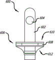
图6图示说明根据本发明的实施方案的典型的分发器连接装置,该分发器连接装置可以被耦合到容器连接装置,例如图4所示的容器连接装置。Figure 6 illustrates a typical dispenser connection device that may be coupled to a container connection device, such as the container connection device shown in Figure 4, according to an embodiment of the present invention.
图7A-B图示说明根据本发明的实施方案的典型的分发器连接装置,该分发器连接装置可以被耦合到容器连接装置,例如图4所示的容器连接装置。7A-B illustrate a typical dispenser connection that may be coupled to a container connection, such as the container connection shown in FIG. 4, according to an embodiment of the present invention.
图8图示说明根据本发明的实施方案的典型的分发器连接装置,该分发器连接装置可以被耦合到容器连接装置,例如图3所示的容器连接装置。FIG. 8 illustrates a typical dispenser connection device that may be coupled to a container connection device, such as the container connection device shown in FIG. 3, according to an embodiment of the present invention.
图9A-B图示说明根据本发明的实施方案的典型的分发器连接装置,该分发器连接装置可以被耦合到容器连接装置。9A-B illustrate a typical dispenser connection that may be coupled to a container connection according to an embodiment of the present invention.
图10图示说明针对流体源和容器之间的流体流,在开启位置被耦合到图6的分发器连接装置的图4的容器连接装置。Fig. 10 illustrates the container connection device of Fig. 4 coupled to the dispenser connection device of Fig. 6 in an open position for fluid flow between the fluid source and the container.
图11图示说明针对流体源和容器之间的流体流,在开启位置被耦合到分发器连接装置的图5的容器连接装置。Figure 11 illustrates the container connection device of Figure 5 coupled to the dispenser connection device in an open position for fluid flow between the fluid source and the container.
图12图示说明根据本发明的实施方案的典型的分发系统的分解视图,该分发系统包括拥有本文所描述的各种特征的具有容器连接装置的容器以及具有分发器连接装置的分发器。Figure 12 illustrates an exploded view of a typical dispensing system including a container with a container connection and a dispenser with a dispenser connection having the various features described herein, according to an embodiment of the present invention.
图13图示说明根据本发明的实施方案的典型的冲洗装置。Figure 13 illustrates a typical flushing device according to an embodiment of the present invention.
图14A-B图示说明用于在使用后将液体从分发系统移除的冲洗装置的一个实施方案。14A-B illustrate one embodiment of a flushing device for removing liquid from a dispensing system after use.
图15图示说明包括如本文所描述的各种实施方案的示例性分发系统,该分发系统包括冲洗装置。Figure 15 illustrates an exemplary dispensing system including various embodiments as described herein that includes a flushing device.
图16A-B图示说明与如本文所描述的容器连接装置一起使用的移除系统的示例性实施方案。16A-B illustrate an exemplary embodiment of a removal system for use with a container connection device as described herein.
图17图示说明根据某些实施方案的分发系统的阀的典型的前、顶、右观察的立体图。17 illustrates a typical front, top, right perspective view of a valve of a dispensing system, according to certain embodiments.
图18图示说明根据某些实施方案的分发系统的阀的典型的顶部平面图。Figure 18 illustrates a representative top plan view of a valve of a dispensing system, according to certain embodiments.
图19图示说明根据某些实施方案的分发系统的阀的典型的后视图。19 illustrates a representative rear view of a valve of a dispensing system, according to certain embodiments.
图20图示说明根据某些实施方案的分发系统的阀的典型的左侧图。Figure 20 illustrates a representative left side view of a valve of a dispensing system, according to certain embodiments.
图21图示说明根据某些实施方案的分发系统的阀的典型的后、左、顶观察的视图。21 illustrates a typical rear, left, top view of a valve of a dispensing system, according to certain embodiments.
图22图示说明根据某些实施方案的分发系统的阀的典型的后、左、底观察的视图。Figure 22 illustrates a typical rear, left, bottom view of a valve of a dispensing system according to certain embodiments.
图23图示说明根据某些实施方案的分发系统的阀的典型的后、左、顶观察的分解图。Figure 23 illustrates a typical rear, left, top view exploded view of a valve of a dispensing system according to certain embodiments.
图24图示说明根据某些实施方案的阀的典型的后、右、顶观察的视图,其中以虚线示出阀块(valve block)和下部块(lower block)以图示说明阀的一些内部部件。Figure 24 illustrates a typical back, right, top view of a valve according to certain embodiments, with the valve block and lower block shown in dashed lines to illustrate some of the interior of the valve part.
图25图示说明根据某些实施方案的阀的典型的剖视图,示出当阀被关闭时螺线管所处的位置。25 illustrates a typical cross-sectional view of a valve showing the position of the solenoid when the valve is closed, according to certain embodiments.
图26图示说明根据某些实施方案的阀的典型的剖视图,示出当阀被打开时螺线管所处的位置。26 illustrates a typical cross-sectional view of a valve showing the position of the solenoid when the valve is opened, according to certain embodiments.
图27A图示说明根据某些实施方案的具有多个阀的分发系统的壳体的典型的前、顶、右观察的视图。27A illustrates a typical front, top, right-side view of a housing of a dispensing system with multiple valves, according to certain embodiments.
图27B图示说明根据某些实施方案的使用者界面的典型的放大视图。Figure 27B illustrates a representative enlarged view of a user interface, according to certain embodiments.
图28图示说明根据某些实施方案的具有多个阀的分发系统的典型的底、前、右观察的视图。28 illustrates a typical bottom, front, right side view of a dispensing system with multiple valves, according to certain embodiments.
图29图示说明根据某些实施方案的分发系统的典型的底视图,示出连接到阀的源管道(source tube)。Figure 29 illustrates a typical bottom view of a dispensing system showing a source tube connected to a valve, according to certain embodiments.
图30图示说明根据某些实施方案的分发系统的典型的底视图,示出具有第一隔热层的源管道。30 illustrates a typical bottom view of a distribution system showing a source conduit with a first layer of insulation, according to certain embodiments.
图31图示说明根据某些实施方案的分发系统的典型的底视图,示出具有第二隔热层的源管道。31 illustrates a typical bottom view of a distribution system showing a source conduit with a second layer of insulation, according to certain embodiments.
图32图示说明根据某些实施方案的典型的冷却系统,示出在传输期间源流体的温度可以如何被控制。Figure 32 illustrates a typical cooling system, showing how the temperature of the source fluid may be controlled during transport, according to certain embodiments.
图33图示说明根据某些实施方案的典型的分发逻辑图。Figure 33 illustrates a typical distribution logic diagram, according to certain embodiments.
图34图示说明根据某些实施方案的典型的分发流程图。Figure 34 illustrates an exemplary distribution flow diagram, according to certain embodiments.
具体实施方式 Detailed ways
在如下的示例性实施方案的说明中,参考所附的形成说明书一部分的附图,在附图中以示例性方式示出本发明可以被实践的具体实施方案。要理解的是,可以使用其他实施方案并且可以进行结构上的改变而不脱离本发明的实施方案的范围。如本文中所使用的,术语“耦合”、“连接”以及“附接”是可互换的,并且包括将一个部分直接地或间接地连接到另一部分的各种形式。再者,应当理解的是,在一个实施方案中所描述的一个或更多个结构特征可以被实施在不同的实施方案中,即使没有具体地提到其作为该实施方案的特征。In the following description of exemplary embodiments, reference is made to the accompanying drawings which form a part hereof, and in which are shown by way of illustrations specific embodiments in which the invention may be practiced. It is to be understood that other embodiments may be utilized and structural changes may be made without departing from the scope of the embodiments of the present invention. As used herein, the terms "coupled," "connected," and "attached" are interchangeable and include various forms of connecting one part to another, directly or indirectly. Furthermore, it should be appreciated that one or more structural features described in one embodiment can be implemented in a different embodiment even if it is not specifically mentioned as a feature of that embodiment.
在如下的说明中,为提供对本发明的全面了解阐述了数个具体细节,例如具体容器和液体的实施例。然而,对本领域技术人员将会是明显的是,本发明可以无需这些具体细节来实践。例如,所述说明一般地根据与小桶(keg)一起使用来将啤酒分发到玻璃杯或大扎杯(pitcher)中的装置来进行讨论;然而,所述装置可以与其他饮料(例如汽水)和其他饮料容器(正如玻璃杯或马克杯(mug))以及除小桶以外的储存容器一起使用。可以用于在公园、音乐会或其他不允许使用玻璃杯的场所盛饮料的一次性小茶杯(cup)也可以视为供选择的容器。供选择地,装置在储存和输送液体的种类方面不受限。例如,根据下面的说明,装置的实施方案可以用于在两个容器之间输送各种流体,例如油。还可以使用所述组件的实施方案来输送气态物质。具体细节可以改变而仍在本发明的精神和范围内。In the following description, numerous specific details are set forth, such as examples of specific containers and liquids, in order to provide a thorough understanding of the invention. It will be apparent, however, to one skilled in the art that the present invention may be practiced without these specific details. For example, the description is generally discussed in terms of a device used with a keg to dispense beer into a glass or pitcher; however, the device can be used with other beverages (such as soda) Use with other beverage containers (like glasses or mugs) and storage containers other than kegs. Disposable cups that can be used to serve beverages at parks, concerts, or other venues where glasses are not permitted are also considered alternative containers. Alternatively, the device is not limited in the types of fluids it can store and deliver. For example, embodiments of the device may be used to transfer various fluids, such as oil, between two containers, as described below. Embodiments of the assembly may also be used to transport gaseous substances. Specific details may be changed while remaining within the spirit and scope of the invention.
本文所描述的流体输送组件及流体输送方法据信在商业应用上提供益处,包括更有效率且更有效果地出售/分碳酸类饮料(例如啤酒),提供新颖的装置(例如,在包含本文所描述的新颖的耦合装置的马克杯或大扎杯的可视的且可能是可移除的部分上使用如标志/标语的信息)来进军目标市场等。本文所描述的流体输送组件和流体输送方法还据信作为可以被用在本地设置(local setting)中的消费产品来提供益处,包括利用碳酸类饮料充注容器以及部分组件的定制。例如,本文所预期的是,家庭或团体可以使用本文所描述的流体输送组件及流体输送方法来举办聚会或者特殊事件,定制容器的可视部分来包括具有描绘聚会主题(例如,“50岁生日”、“家庭年度烧烤”等)的图片和/或文本的信息。其他实施例包括运动队代表、婚礼图像、逗乐的图片、笑话等。如下面所描述的,容器或组件的这样的可视部分(例如,磁性帽)可以为可移除的,来为每个参加聚会或特殊事件的人员提供可带回家的纪念品。The fluid delivery assemblies and fluid delivery methods described herein are believed to provide benefits in commercial applications, including more efficient and effective vending/dispensing of carbonated beverages (e.g., beer), providing novel devices (e.g., The visible and possibly removable portion of the mug or mug of the described novel coupling device uses information such as a logo/slogan) to reach target markets and the like. The fluid delivery assemblies and fluid delivery methods described herein are also believed to provide benefits as consumer products that can be used in local settings, including filling containers with carbonated beverages and customization of parts of the assembly. For example, it is contemplated herein that a family or group may host a party or special event using the fluid delivery assemblies and fluid delivery methods described herein, customizing the visual portion of the container to include a display with a theme depicting the party (e.g., "50th Birthday ", "Annual Family BBQ", etc.) with pictures and/or text information. Other examples include sports team representatives, wedding images, amusing pictures, jokes, and the like. As described below, such a visible portion of the container or assembly (eg, a magnetic cap) can be removable to provide a take-home keepsake for each party or special event attendee.
在一个实施方案中,提供用于通过容器底部充注容器的方法。经由本文所描述的装置和方法的使用来通过底部充注容器是有益的,例如在控制所产生的泡沫的量方面以及相对于传统方法显著地减少碳酸类饮料(例如汽水或啤酒)上的“头(head)”方面。此外,以通过容器底部来充注的方式,泡沫被向上推并超过容器的边缘(rim),从而减少被浪费的饮料的量。服务人员也可以通过无需在倾倒时握持并倾斜玻璃杯或大扎杯以移除泡沫而获益。另外,由于多于一种类型的饮料可以从同一系统中倾倒出,龙头的数目可以被减少。可替换的实施方案包括用来通过底部充注容器的分发系统组件和装置。系统的其他实施方案包括用来在使用操作之间进行清洗的液体清空部件,以及用于在充注容器后移除饮料的快速排放附件。In one embodiment, a method for filling a container through the bottom of the container is provided. Bottom-filling containers via the use of the devices and methods described herein is beneficial, for example, in controlling the amount of foam produced and significantly reducing the " Head (head)" aspect. Furthermore, by filling through the bottom of the container, the foam is pushed up and over the rim of the container, thereby reducing the amount of beverage that is wasted. Servers also benefit from not having to hold and tilt the glass or tumbler to remove foam while pouring. Additionally, the number of taps can be reduced since more than one type of beverage can be poured from the same system. Alternative embodiments include dispensing system components and devices for filling containers through the bottom. Other embodiments of the system include a liquid emptying feature for cleaning between uses, and a quick discharge attachment for removing the beverage after filling the container.
在一个实施方案中,分发系统被用来分发各种流体,包括饮料,诸如啤酒、软饮料、碳酸饮料等。流体可以通过与分发系统相关联的注嘴来分发。注嘴可以在流体容器的底部耦合到该流体容器。分发系统可以包括使用者界面,包括使得使用者能够指定分发模式、分发量等的选项。使用者界面可以与处理器相关联。分发系统可以以自动模式、半自动模式或手动模式分发流体。传感器可以被用来检测流体容器何时被恰当地放置在分发平台上。传感器还可以被用作安全装置来防止流体在任何模式下流动,除非流体容器被恰当地置放到分发平台上。传感器可以进一步被用来指示分发系统何时流体容器已经被移除,从而分发系统可以重置以进行下一次充注或者执行冲洗以进行清洗。In one embodiment, the dispensing system is used to dispense various fluids, including beverages, such as beer, soft drinks, carbonated drinks, and the like. Fluid may be dispensed through nozzles associated with the dispensing system. A nozzle can be coupled to the fluid container at the bottom of the fluid container. The dispensing system may include a user interface, including options that enable the user to specify the mode of dispensing, the amount of dispensing, and the like. A user interface can be associated with the processor. The dispensing system can dispense fluid in automatic mode, semi-automatic mode or manual mode. Sensors can be used to detect when a fluid container is properly placed on the dispensing platform. The sensor can also be used as a safety device to prevent fluid flow in any mode unless the fluid container is properly placed on the dispensing platform. Sensors can further be used to indicate to the dispensing system when a fluid container has been removed so that the dispensing system can be reset for another fill or perform a flush for cleaning.
图1图示说明用来通过容器底部充注容器的设计的根据实施方案的连接到饮料分发器的典型的容器。参照图1,分发器100被示出包括耦合的且准备来被充注的容器102。分发器100可以用来分发饮料,包括碳酸类饮料,例如汽水、啤酒等。容器102可以为用来接收液体的任何容器,包括例如品脱玻璃杯、马克杯、一次性杯或者大扎杯。容器102可以在容器102的底部104或者接近容器102的底部104耦合到分发器100。因此,在分发过程中容器102在充注饮料的平面下被充注。Figure 1 illustrates a typical container connected to a beverage dispenser according to an embodiment of a design for filling the container through the bottom of the container. Referring to FIG. 1 , a
在一个实施方案中,容器102包括被设计来耦合到分发器连接装置108的容器连接装置106。分发器100可以被耦合到流体源,例如小桶或碳酸类饮料和汽水管线。容器连接装置106可以包括阀,当被耦合到分发器连接装置108时所述阀打开而允许流体流通过。当容器102从分发器100移除时,容器连接装置106则可以关闭,从而防止从容器102泄漏。分发器100包括壳体110,壳体110被成形来使容器连接装置106和分发器连接装置108恰当地对准。分发器100还可以包括水槽112来接住任何潜在的溢出液体。水槽112可以包括各种形状,例如碗、凸起的边沿(lip)或凹陷的区域。水槽112可以包括排放部件114用来容易地清除已接住的液体。In one embodiment, the
根据本发明的一个方面,在使用期间,容器102被耦合到分发器100。当形成附接时,容器连接装置106和分发器连接装置108接合来创建容器和流体源之间的流径,从而容器102从其底部部分(bottom portion)被充注。使用者可以使容器充溢来移除在充注过程中可能在容器的顶部产生的任何额外的泡沫。可替换地,在移除或充注过程中一些流体可能漫出。水槽112被设计来接住溢出的流体,所述流体可以通过排放部件114被移除来便利清洗。当容器102从分发器100移除时,容器连接装置106可以与分发器连接装置108脱离,来密封容器102防止泄漏。According to one aspect of the invention,
在一个实施方案中,分发器100可以为可从流体源移除的、但通过软管或管道或其他流体传输装置来耦合的分离装置。分发器100可以被并入或耦合到固定表面,例如工作台面,或者可以为按照使用者的方便来安排的独立地可移动的平台。分发器100还可以为各种形状,并且包括附加特征,例如壳体110、水槽112或排放部件114。分发器100可以可替换地包括音频或视频装置。例如分发器100可以包括辨识与具体分发器相关联的内容物的信息、标志或者设计。在一个实施方案中,分发器100可以包括当容器102被连接到分发器时打开的灯(所述灯可以为彩色的或者闪光灯)或者扬声器。In one embodiment,
图2图示说明当容器202被耦合到分发器连接装置204时,从闭合液体保持状态到开启液体充注状态的容器202的示例性实施方案的典型进程。在一个实施方案中,容器连接装置包括阀,例如通常为闭合的帽206。帽206被耦合到容器202的底部,并且可以包括液体紧密密封件来防止流体流出容器的底部。FIG. 2 illustrates a typical progression of an exemplary embodiment of a
在一个实施方案中,帽206可以被用作在消费者饮用其饮料时对消费者是可视的广告看板。例如,在这样的实施方案中,帽206可以包括用于宣传商业企业或向消费者传达其他信息的标志、图像等。在一个实施方案中,帽206本身或其可移除的部分包括磁性材料和商业信息,从而起到宣传公司或产品的作用。例如,磁体可以具有公司名称和/或标志并且可以被消费者带回家作为纪念品,来用在冰箱或其他金属结构上,从而公司名称和/或标志可以被显著地展示。In one embodiment, the
当被耦合到容器202时,分发器连接装置204可以包括打开帽206并且允许分发器连接装置204和容器202之间的流体流过的装置。分发器连接装置204可以耦合到液体储存容器,例如小桶、桶或其他容器。分发器连接装置204可以包括用于将液体从储存容器(未示出)输送到分饮料的或其他容器202的导管204。导管一般地可以为挠性的,用来将内容物从储存的地方导引到分发的地方,而不扭结或阻碍流体流径。When coupled to
图2A图示说明在闭合结构中、能够容纳流体的容器202。容器202可以为任何饮料容纳器皿,包括小茶杯(cup)、大扎杯、品脱杯(pint)、马克杯或诸如此类,或者任何非固体的(non-solid)容纳器皿。容器202包括可以用来支撑容器202的底部208,以及用来保持流体的侧壁。容器202还包括用来分发所容纳的流体的顶部开口,例如用来倾倒或饮用。底部208具有与顶部开口分开的底部开口,用于在充注期间允许流体流过。当容器不是正在被充注时,底部开口可以由创建流体紧密密封的阀盖住。在一个实施方案中,阀包括通常被偏置为闭合来创建流体紧密密封的帽206。帽206可以包括与容器202的底部208上的环210的互补磁性材料相吸引的磁性材料。环210可以一般地包围孔(hole)的外缘(outer edge),而帽206具有一定的形状和盖住孔的直径,并且可以与环的至少一部分交叠(overlap)。Figure 2A illustrates a
图2B图示说明容器202与分发器连接装置204接触,而容器的阀没有被打开。分发器连接装置204与容器202的底部开口对准。容器202的帽206通过例如对环210的磁性吸引而被偏置为闭合的。分发器连接装置204包括注嘴212,注嘴212具有用于在充注期间允许流体流过的孔214。注嘴212被选择尺寸来和容器202的底部开口内部相称。注嘴212推抵帽206并且打开容器202的阀来允许流体流过以进行充注。Figure 2B illustrates
图2C图示说明当容器的阀被打开来进行充注时,耦合到分发器连接装置204的容器202。注嘴212随着注嘴进入容器202而推抵帽206并露出孔214。在一个实施方案中,一旦容器202和分发器连接装置204耦合,通过打开分发器连接装置204上的阀来允许流体流动。在可替换的实施方案中,当孔露出时流体自动地流过。例如,分发器连接装置204中的液体可以被保持在压力下。当不使用时,孔214可以被平台216盖住。当容器202被耦合到饮料分发器时,注嘴212可以推抵帽206,打开容器的阀,而容器的底部208推抵平台216,露出孔214。一旦孔214被露出,液体可以通过孔214从分发器连接装置204流入容器202。Figure 2C illustrates
当注嘴212从容器202的底部移除时,容器的阀闭合并且密封容器,从而液体被容纳于其中。当阀被密封时,容器202可以用来容纳新加入的液体。在一个实施方案中,帽206被不断地吸引到环210。当注嘴212的影响被移除时,帽206放置在相对于环210的闭合位置,密封容器202。来自分发器连接装置204的流体可以通过闭合饮料分发器上的阀而被容纳。在一个实施方案中,由于帽206密封容器202,平台216密封孔214。因此,当容器202没有被附接时,流体被阻止自由地流出分发器连接装置204。When the
图3-5图示说明耦合在容器底部的容器连接装置的典型实施方案。如上所述的,容器连接装置可以被设计来耦合到分发器连接装置。容器连接装置可以包括阀,当被耦合到分发器连接装置时所述阀打开而允许流体流过其中。当容器从分发器移除时,容器连接装置则可以闭合,防止来自容器的任何泄漏。Figures 3-5 illustrate an exemplary embodiment of a container attachment device coupled to the bottom of a container. As mentioned above, the container connection device may be designed to couple to the dispenser connection device. The container connection may include a valve that opens to allow fluid flow therethrough when coupled to the dispenser connection. When the container is removed from the dispenser, the container connection means can then be closed preventing any leakage from the container.
图3图示说明从顶部看到的容器底部300的典型实施方案,容器底部300包括孔302、帽304以及环306。孔302在充注期间可以允许流体从容器的底部流过。环306可以围绕孔302的周缘(circumferential edge)。帽304可以盖住孔302以及环306的至少一部分,并且可以悬挂(overhang)环306。帽304和环306可以包括磁性材料,例如含铁金属。磁性特性将帽304吸引到环306,密封孔302。帽304可以例如通过到环306的磁性吸引而被耦合到容器底部300,从而帽304可以被容易地移除。环306可以更永久地耦合到容器底部300,例如通过粘合剂、螺丝或一体地模制到容器底部中。帽304和/或环306可以包括密封装置,例如O型环或垫圈,来更好地确保围绕孔302的流体紧密密封。可替换地,容器底部300可以在帽304和环306之间包括密封材料(例如橡胶)来创建流体紧密密封。FIG. 3 illustrates an exemplary embodiment of a
帽304可以为各种形状。例如,在一个实施方案中,帽可以为平坦的、与容器底部300内部相称的一般为圆形的盘。可替换地,帽304可以包括轮廓相合化(contoured)表面来与孔302配合,以使帽304和孔302恰当地对准,或者为孔创建更好的密封。在一个实施方案中,帽304可以被轮廓相合化来与分发器连接装置配合。例如,帽304在下侧可以包括凹陷的轮廓来接收分发器连接装置的一部分,并且在充注过程中将帽304保持在期望的位置。
图4A-B图示说明容器连接装置400的典型实施方案,容器连接装置400包括能够在容器的底部连接在一起的上部分(upper section)和下部分(lower section)。图4A图示说明上部分和下部分的典型实施方案在未装配状态的截面视图,而图4B图示说明所述典型实施方案在装配状态的截面视图,其中上部分和下部分附接到一起并且围绕底部开口附接到容器。容器连接装置400的可附接的部分允许容器连接装置的移除,来进行清洗或与其他容器一起使用。上部分和下部分402、404可以被螺接来通过容器406的底部上的开口408彼此接合。这些部分可以可替换地通过其他方式来连接,例如胶合或粘合。容器连接装置可以可替换地被直接集成到容器底部中。4A-B illustrate an exemplary embodiment of a
在一个实施方案中,上部分402可以耦合到下部分来形成容器连接装置400。下部分404可以包括一般地为圆柱形的轴410,轴410具有比容器406的底部上的开口408小的直径。开口408的直径和轴410一般地可以为相同大小来形成紧配合(snug fit),以帮助减少泄漏和容器连接装置400与容器406之间恰当地对准。轴410可以可替换地为相对地小于容器406中的开口408,来允许可替换地选择要被耦合到容器底部的容器连接装置的大小。轴410的内直径可以被选择大小并被成形来适应如下面进一步说明的分发器连接装置。轴410的外侧可以包括螺纹412来接合上部分402。上部分402在形状上一般地可以为具有内开口414的圆柱形,内开口414包括螺纹416来接合下部分404的螺纹412。In one embodiment,
下部分404在轴410的基部还可以包括凸缘418。凸缘418可以具有大于开口408的外直径,来提供表面以接合容器406底部。凸缘418可以包括密封件420,例如O型环或垫圈。当上部分402接合下部分404时,密封件420可以压抵容器406的底部侧边以创建流体紧密密封。上部分402也可以在底部侧边上包含密封件422,来压抵容器406的顶面。因此,容器406的一部分可以被夹在容器连接装置的上部分402和下部分404上的密封件之间。The
容器连接装置400包括帽430,帽430具有磁性材料以及被配置来与上部分402配合的形状。在一个实施方案中,上部分402包括具有内表面的边缘428,所述内表面与帽430的外表面配合。当然,在可替换的实施方案中,所述边缘可以具有用来与帽的内表面配合的外表面。边缘428一般地可以为具有倾斜的内缘(inner edge)的圆柱形边缘,来将帽430导引到上部分402的内开口414上的中心位置。在分发器连接装置将帽压离上部分时,所述倾斜的内缘允许于上部分402和帽430之间形成空间。在一个实施方案中,上部分402包括用于吸引帽430中的磁体432的磁体424,以将帽偏置于闭合位置。这两个磁体424和432可以为耦合到各自的部分的环或分离的磁性部件。磁体可以被粘附、粘合、一体地形成、模制或者附接到各自的部分,以将帽吸引到上部分。可替换地,用于上部分和/或帽的材料可以为磁性的。在一个实施方案中,帽430可以包括凹陷434,来与分发器连接装置(未示出)配合。凹陷434可以接收所述分发器连接装置的一部分,通过将帽430向上推并且在帽430和上部分402之间提供空间来打开阀。当所述分发器连接装置被移除,帽和上部分之间的磁性吸引使阀闭合,并且上部分的边缘确保恰当的对准。上部分和/或帽可以包括密封件,例如O型环或垫圈,来在阀被闭合时进一步防止泄漏。The
在一个实施方案中,容器连接装置400可以包括一个或更多个磁体。如上所述的,上部分402可以包括磁体,所述磁体用于吸引帽430以作为用于容器连接装置400的阀。在一个实施方案中,下部分404可以包括磁体426,磁体426用来将容器连接装置400耦合到分发器连接装置(未示出)。磁体426可以被胶合、粘附、粘合、一体地模制或者附接到下部分404,例如在凸缘418中。磁体426可以吸引被包括在分发器连接装置的基部或一部分上的另一磁体或磁性材料,来在充注期间稳固容器。容器连接装置400还可以包括一个或更多个密封件,来提供容器连接装置和分发器连接装置之间的流体密封连接。例如,下部分404可以包括用于耦合分发器连接装置的密封件436。上部分402可以包括密封件438和/或帽430可以包括密封件440,来在容器连接装置400在闭合位置时提供帽430和上部分402之间的流体密封连接。密封件可以为本领域技术人员已知的任何密封装置,例如O型环或垫圈。In one embodiment,
图5A-B根据设计的各方面图示说明容器连接装置的典型实施方案,所述容器连接装置能够连接到容器的底部。图5A为在闭合流体密封位置的容器连接装置,而图5B为相同的容器连接装置被示出在开启位置。当阀被闭合,创建液体紧密密封来在容器被充注时防止泄漏。当阀被打开,液体可以从另一源输送到容器。上部分502可以与下部分504连接,来允许容器连接装置500容易地与容器耦合/与容器脱离。如在图4B中所示的以及上面所描述的,上部分502可以被改变,从而帽530无法自由地与上部分502解除关联(disassociated)。5A-B illustrate an exemplary embodiment of a container attachment device capable of attaching to the bottom of a container in accordance with aspects of the design. Figure 5A is the container connection device in the closed fluid tight position, while Figure 5B is the same container connection device shown in the open position. When the valve is closed, a liquid tight seal is created to prevent leakage when the container is filled. When the valve is opened, liquid can be delivered to the container from another source. The
在一个实施方案中,上部分502可以包括一般地为圆柱形的边缘528,边缘528周边地(circumferentially)围绕帽530。帽530被允许沿边缘的纵轴上下平移,但被阻止从上部分502完全地脱离。例如,帽530一般地可以为圆柱形按钮,所述按钮具有周边地围绕中心部分的凸缘。所述凸缘可以放置在上部分502的内表面上的凹口内。凹口的高度大于凸缘的高度,从而帽可以在凸缘接触凹口的两个侧表面(subscribing surfaces)之间所限定的距离内平移。在一个实施方案中,上部分502还包括在帽530在开启位置时创建流体流径的孔536。例如,当帽530在上面位置或者开启位置,下部分504的轴和上部分502的孔536之间的通道被创建。当帽530在下面位置或闭合位置时,所述通道被密封。帽530、上部分502和/或下部分504可以包括密封件,来于帽在闭合位置时防止流体泄漏。帽530、上部分502和/或下部分504可以包括磁体,来将帽530偏置于闭合位置。In one embodiment,
图6-9图示说明分发器连接装置的典型实施方案。如上所述的,分发器连接装置可以被设计来耦合容器连接装置。分发器连接装置可以连接流体源,例如小桶或苏打饮料机糖浆以及碳酸化容器。如上面图1中所讨论的,分发器连接装置可以包括附加特征,例如基部、水槽、排水部件、广告区域、灯、音频部件等。容器连接装置和分发器连接装置的不同实施方案可以被改变来包括不同实施方案的特征。下面根据相应的典型容器连接装置描述分发器连接装置的典型实施方案,但对本领域技术人员来说明显的是,这些装置可以被混合或改变。Figures 6-9 illustrate exemplary embodiments of dispenser connection means. As mentioned above, the dispenser connection device may be designed to couple to the container connection device. The dispenser connection may connect to a fluid source such as a keg or soda maker syrup and carbonation container. As discussed above in FIG. 1 , the dispenser connection device may include additional features such as bases, sinks, drain components, advertising areas, lights, audio components, and the like. Different embodiments of the container attachment means and the dispenser attachment means may be altered to include features of the different embodiments. Exemplary embodiments of dispenser attachment means are described below in terms of corresponding exemplary container attachment means, but it will be apparent to those skilled in the art that these means may be mixed or varied.
图6图示说明根据本发明的实施方案的典型的分发器连接装置600,分发器连接装置600可以被耦合到例如图4A-B中所示出的容器连接装置。分发器连接装置600包括刚性构件或注嘴602,刚性构件或注嘴602包括沿纵轴的通道以及一个或更多个穿过刚性构件或注嘴602的侧壁的孔604。刚性构件或注嘴的通道与流体源流体连通。注嘴602被设计为通过推抵容器连接装置400的阀构件(例如帽430)来打开容器连接装置400。注嘴602的顶部可以被轮廓相合化或被成形来与帽430的凹陷434配合,因此所述帽由所述注嘴保持。分发器连接装置600可以包括磁体或磁性材料,来固定容器连接装置400。例如,分发器连接装置600可以包括平台606,平台606包括磁性环608,磁性环608耦合到容器连接装置400的下部分404的磁体426。分发器连接装置600还可以包括密封件610,来创建在分发器连接装置600和容器连接装置400之间的流体密封连接。圈612可以被耦合在平台606和注嘴602之间来允许所述平台沿注嘴602的纵轴平移。Figure 6 illustrates a typical
图7A-B图示说明根据本发明的实施方案的典型的分发器连接装置700,分发器连接装置700可以被耦合到例如图4A-B中所示出的容器连接装置。图7A图示说明分发器连接装置700在闭合位置,而图7B图示说明分发器连接装置700在开启位置。与图6类似,分发器连接装置700可以包括具有孔704的注嘴702,来创建在流体源和分发器装置之间到容器的流体路径。分发器连接装置还可以包括平台706,平台706包括密封件708来防止分发器连接装置700和容器连接装置之间的流体泄漏。Figures 7A-B illustrate a typical dispenser connection device 700 that may be coupled to a container connection device such as that shown in Figures 4A-B, according to an embodiment of the present invention. Figure 7A illustrates the dispenser connection device 700 in the closed position, while Figure 7B illustrates the dispenser connection device 700 in the open position. Similar to FIG. 6, the dispenser connection device 700 may include a nozzle 702 having an aperture 704 to create a fluid path between the fluid source and the dispenser device to the container. The dispenser connection may also include a platform 706 that includes a seal 708 to prevent fluid leakage between the dispenser connection 700 and the container connection.
在一个实施方案中,分发器连接装置可以包括圈710。圈710可以用来将平台706保持到分发器连接装置700。此外,圈710可以用来在分发器不使用时盖住注嘴702,从而潜在地减少泄漏或减少污染或者防止残屑(debris)进入分发器。平台706还可以包括边缘712,边缘712可以用来在分发器不使用时密封注嘴702。边缘712可以包括成角度的外周壁,从而顶缘(top edge)的直径比起下缘(lower edge)来是被减小的。减小的顶部直径可以帮助使分发器连接装置和容器连接装置恰当地对准。In one embodiment, the dispenser connection means may include a loop 710 . Loop 710 may be used to hold platform 706 to dispenser connection 700 . Additionally, collar 710 may be used to cover nozzle tip 702 when the dispenser is not in use, thereby potentially reducing leakage or reducing contamination or preventing debris from entering the dispenser. The platform 706 can also include a lip 712 that can be used to seal the nozzle tip 702 when the dispenser is not in use. Edge 712 may include an angled peripheral wall such that the diameter of the top edge is reduced compared to the lower edge. The reduced top diameter can assist in proper alignment of the dispenser connection and container connection.
图8图示说明根据本发明的实施方案的典型的分发器连接装置850,分发器连接装置850可以被耦合到例如图3中所示出的容器连接装置。分发器连接装置850可以与容器底部300配合来在充注期间密封流体分发器和容器之间的连接。分发器连接装置850可以被耦合到工作台面或其他服务平台(未示出)。分发器连接装置850可以被耦合到液体储存容器、到所述液体储存容器的导管或诸如此类。Figure 8 illustrates a typical dispenser connection 850 that may be coupled to a container connection such as that shown in Figure 3, according to an embodiment of the present invention. Dispenser connection 850 may cooperate with
在一个实施方案中,分发器连接装置850可以包括注嘴852。注嘴852一般地可以为圆柱形形状的、被选择尺寸来刚好安置到孔302中的喷嘴。注嘴852可以用来推抵帽304以破除其利用环306的密封。注嘴852可以包括一个或更多个孔854,这允许液体流过并分发到容器中(未示出)。饮料分发器可以包括开关,来在一旦容器被耦合到分发器连接装置时允许流体流过。注嘴852可以包括沿其顶缘的盘(disc)862。盘862可以用来提供广告看板,或者可以用来辨识被耦合到饮料分发器的饮料。例如,盘862可以替代当今用在设施中的现有的啤酒龙头(beer tap),来指示饮料的类型并且可以具有其他怀旧的可能性(nostalgic possibilities),例如当品牌停用时分发奖品。In one embodiment, the dispenser connection 850 can include a nozzle 852 . Nozzle 852 may generally be a cylindrically shaped nozzle sized to fit snugly into
在一个实施方案中,分发器连接装置850可以包括平台856,来帮助使容器和分发器恰当地对准。平台856可以被成形来定心并将容器耦合到注嘴852。作为实施例,平台856的外缘在形状上可以一般地为圆柱形,来符合容器上底部边缘的内表面。平台856的外缘可以呈微锥形来将容器的底部边缘导引到位并使容器和注嘴852恰当地对准。可替换地,平台可以包括上边缘(未示出),容器的外缘可以刚好安置到其中。上边缘可以为梯状的来使各种大小的容器和注嘴852恰当地对准。In one embodiment, the dispenser attachment 850 may include a platform 856 to assist in proper alignment of the container and dispenser. The platform 856 can be shaped to center and couple the container to the nozzle 852 . As an example, the outer edge of the platform 856 may be generally cylindrical in shape to conform to the inner surface of the upper bottom edge of the container. The outer edge of the platform 856 may be slightly tapered to guide the bottom edge of the container into place and to properly align the container and nozzle 852 . Alternatively, the platform may include an upper edge (not shown) into which the outer edge of the container may fit. The upper edge may be stepped to allow proper alignment of various sized containers and nozzles 852 .
在一个实施方案中,为在流体分发器没有被耦合到容器时防止从流体分发器的泄漏,孔854可以被平台856盖住。平台856可以用来在不使用时密封孔854。在一个实施方案中,在闭合位置时,平台856周边地围绕孔854。平台856可以在注嘴852上轴向地滑动,允许平台856在充注期间将孔854露出。在使用期间,容器底部300可以在平台856上推动,而允许注嘴852通过孔302进入,并且从而将孔854露出。平台856可以在充注后回到闭合位置。平台856可以在偏置力(例如弹力)下移动。可替换地,随着容器被提升来将平台856从注嘴移除,平台856可以在平台和容器之间的磁性吸引的影响下回到闭合位置。平台856和/或注嘴852可以包括摩擦连接(包括止动器和凸缘)来相对于注嘴将平台固定于闭合位置。这样的连接可以通过容器在平台上的向下的力来被解决(overcome),并且从而打开注嘴的流径。在一个实施方案中,所描述的密封平台可以用作阀,来启动饮料分发器和容器之间的流动,从而允许注嘴852的孔854一露出流体即流过。In one embodiment, to prevent leakage from the fluid dispenser when the fluid dispenser is not coupled to the container, the aperture 854 can be covered by a platform 856 . The platform 856 can be used to seal the hole 854 when not in use. In one embodiment, the platform 856 circumferentially surrounds the aperture 854 when in the closed position. The platform 856 can slide axially over the nozzle 852, allowing the platform 856 to expose the hole 854 during filling. During use,
分发器连接装置可以包括磁体或磁性材料,来吸引容器连接装置中相应的磁体或磁性材料。例如,平台856可以包括环864,环864包括在充注期间可以用来将容器固定到平台856的磁性材料。平台856的环864可以用来吸引容器底部300上的环306。在一个实施方案中,盘862可以包括磁性材料,来当容器被放置在注嘴852上且在开启位置时保持容器连接装置的帽304。The dispenser attachment may include a magnet or magnetic material to attract a corresponding magnet or magnetic material in the container attachment. For example, the platform 856 can include a ring 864 that includes magnetic material that can be used to secure the container to the platform 856 during filling. The ring 864 of the platform 856 can be used to attract the
平台856和/或注嘴852可以包括一个或更多个密封件,用于注嘴和平台以及容器之间的流体密封连接。例如,注嘴可以包括用于密封孔854的上缘(upper edge)的密封件858,而平台856可以包括用于在闭合位置时密封孔854的下缘的密封件860。平台856可以包括在上表面上的密封件866,来在开启位置时创建容器和平台之间的密封。密封件可以包括橡胶O型环或其他垫圈材料,用来保持流体紧密密封。Platform 856 and/or nozzle 852 may include one or more seals for a fluid-tight connection between the nozzle and platform and container. For example, the nozzle may include a seal 858 for sealing the upper edge of the bore 854, while the platform 856 may include a seal 860 for sealing the lower edge of the bore 854 when in the closed position. The platform 856 may include a seal 866 on the upper surface to create a seal between the container and the platform when in the open position. Seals may include rubber O-rings or other gasket materials to maintain a fluid-tight seal.
平台856和/或注嘴852可以被成形来阻止平台856滑离注嘴852的端部。例如,平台856的上缘可以具有较大的内直径,相对于注嘴852的顶部(例如在密封件858处)放置。注嘴852的顶部可以具有更大的外直径来匹配平台856的较大的内直径。注嘴852的更大的外直径可以阻止平台856滑离注嘴的上缘。密封件858可以在当注嘴和平台在闭合位置时创建密封的同时,用作注嘴852的更大的外直径来将平台856保持到注嘴852。这样的实施方案可以容易的安装,因为在加入密封件858前平台856可以在注嘴852的顶部上滑动用来进行安装。The platform 856 and/or nozzle 852 may be shaped to prevent the platform 856 from sliding off the end of the nozzle 852 . For example, the upper edge of platform 856 may have a larger inner diameter, positioned relative to the top of nozzle 852 (eg, at seal 858). The top of nozzle 852 may have a larger outer diameter to match the larger inner diameter of platform 856 . The larger outer diameter of the nozzle 852 prevents the platform 856 from sliding off the upper edge of the nozzle. The seal 858 can serve as a larger outer diameter of the nozzle 852 to hold the platform 856 to the nozzle 852 while creating a seal when the nozzle and platform are in the closed position. Such an embodiment can be easily installed because the platform 856 can be slid on top of the nozzle 852 for installation before the seal 858 is added.
图9图示说明根据本发明的实施方案的典型的分发器连接装置900,分发器连接装置900可以被耦合到容器连接装置。图9A图示说明分发器连接装置900在闭合位置,而图9B图示说明分发器连接装置900在开启位置。分发器连接装置900可以包括用于通过容器底部充注容器的注嘴902。注嘴902可以包括孔908,用来在饮料分发器和容器之间创建流体流径。分发器连接装置900包括注嘴902和围绕所述注嘴的平台904,平台包括开口912,通过开口912注嘴被允许平移。所述平台被直接附接到在图9A-B中示出为挠性构件的圈906,所述平台在分发器连接装置闭合位置盖住注嘴的孔908,而在分发器连接装置开启位置露出孔908。Figure 9 illustrates a typical
除了由挠性材料制成来允许平台904相对于注嘴902平移之外,圈906可以由液体密封材料形成,例如橡胶或塑料,以防止从注嘴902泄漏。在分发器连接装置闭合位置,平台904开口一般地被放置为与注嘴的端面相一致。在分发器连接装置开启位置,所述圈向外弯曲来使平台904相对于注嘴902沿注嘴902的纵轴平移,从而注嘴902移动通过平台904的开口912。In addition to being made of a flexible material to allow
如在图6中所描述的,圈906可以用来替代密封件或除了使用密封件以外还使用圈906。可替换地,在不使用时,圈906可以盖住孔908的至少一部分并且阻止流体流过。圈906可以通过各种方式被耦合在分发器连接装置900和平台904之间。在一个实施方案中,分发器连接装置900和平台904围绕边沿包括凹口。在这样的实施方案中,圈906相应地包括突起,所述突起被选择尺寸来刚好安置在凹口中并且超出分发器连接装置900和平台904的相应的边沿。所述边沿和凹口可以用来相对平台904和分发器连接装置900以摩擦的方式紧紧保持圈906,创建流体紧密密封。可替换地,或者除此之外还有,可以使用粘合剂来使圈906和平台904耦合。As depicted in FIG. 6,
平台904可以包括边缘910,边缘910相对于注嘴902恰当地放置容器。边缘910可以为叉型耦合器或者可以为坚实的边缘或其结合,所述叉型耦合器包括一个或更多个叉状物(prongs),所述坚实的边缘可以包括梯状底部来适应各种大小的容器。如文本所描述的或本领域技术人员已知的其他实施方案,可以可替换地用来放置或保持容器。密封件914可以被包括在平台904的基部上表面上,来利用容器创建密封。密封件914可以周边地围绕开口912。The
分发器连接装置900可以包括磁体或磁性材料来耦合容器连接装置。例如,平台904还可以包括被并入磁性材料或含铁材料或者由磁性材料或含铁材料形成的环916,来在充注期间将容器连接装置固定到平台。在一个实施方案中,注嘴902的顶部包括盘918,盘918在充注期间可以用来保持容器连接装置(未示出)的帽。盘918可以包括磁体或磁性材料来吸引帽和/或可以被轮廓相合化来与帽的相应轮廓配合。在一个实施方案中,盘918可以包括信息,例如由分发器所分的饮料的类型或品牌、广告材料等。The
图10-11图示说明耦合到分发器连接装置的容器连接装置的典型实施方案。当附接形成时,容器连接装置和分发器连接装置接合来创建容器和流体源之间的流体路径。容器则可以从容器的一底部部分被充注。当容器从分发器移除时,容器连接装置与分发器连接装置脱离,并且密封容器防止泄漏。10-11 illustrate an exemplary embodiment of a container connection device coupled to a dispenser connection device. When the attachment is formed, the container connection means and the dispenser connection means engage to create a fluid path between the container and the fluid source. The container can then be filled from a bottom portion of the container. When the container is removed from the dispenser, the container attachment is disengaged from the dispenser attachment and the container is sealed against leakage.
图10图示说明针对流体源和容器之间的流体流,在开启位置被耦合到图6的分发器连接装置的图4A-B的容器连接装置。当被连接时,注嘴602推抵帽430来克服上部分磁体424和帽磁体432之间的磁性吸引,以使孔604露出到容器406的内部。在这个过程中,由于平台606中的磁体608吸引容器连接装置的下部分404的磁体426,容器406同样由平台606中的磁体608来稳固。如所示出的,注嘴602头部被成形为适应帽430的凹陷434,来在充注过程中将帽维持为恰当的对准。10 illustrates the container connection device of FIGS. 4A-B coupled to the dispenser connection device of FIG. 6 in an open position for fluid flow between the fluid source and the container. When connected,
图11图示说明针对流体源和容器之间的流体流,在开启位置耦合到分发器连接装置1100的图5A-B的容器连接装置500。当被连接时,注嘴1102推抵帽530来克服上部分502和帽530之间的闭合偏置,从而露出边缘528的孔536。在这个实施方案中,帽可以通过磁性吸引、弹力或适用于装置的其他偏置力被偏置为闭合的。FIG. 11 illustrates the
图12为根据本发明实施方案的典型分发系统的分解视图,所述分发系统包括具有容器连接装置的容器以及具有分发器连接装置的分发器,其中每个均包括文本所描述的各种特征。本领域技术人员将能够将本文所描述的这些和其他特征结合到不同的实施方案中,所有这些均在本发明的范围内。系统1200包括具有容器连接装置1202的容器,以及具有分发器连接装置1204的分发器。12 is an exploded view of an exemplary dispensing system including a container with container attachment means and a dispenser with dispenser attachment means, each of which includes various features described herein, according to an embodiment of the present invention. Those skilled in the art will be able to combine these and other features described herein into various embodiments, all of which are within the scope of the invention. System 1200 includes a container with a container connection 1202 and a dispenser with a dispenser connection 1204 .
在一个实施方案中,容器1206包括容器连接装置1202。容器连接装置1202包括帽1208、帽壳体磁体1210、密封件1212、边缘1214、边缘壳体磁体1216、密封件1218、底部区1222以及底部壳体磁体1220。磁体1210、1216、1220可以为刚好安置在容器连接装置的各种凹口中的一个或更多个磁性部件、固体磁性环或者被并入容器连接装置的各自的部件的材料。密封件1212、1218可以为任何密封装置,例如O型环或橡胶垫圈。In one embodiment, container 1206 includes container connection device 1202 . Container attachment device 1202 includes cap 1208 , cap housing magnet 1210 , seal 1212 , rim 1214 , rim housing magnet 1216 , seal 1218 , bottom region 1222 , and bottom housing magnet 1220 . The magnets 1210, 1216, 1220 may be one or more magnetic components, solid magnetic rings, or materials incorporated into the respective components of the vessel connection device that fit snugly into the various recesses of the vessel connection device. The seals 1212, 1218 may be any sealing means, such as O-rings or rubber gaskets.
在一个实施方案中,帽壳体磁体1210包括围绕帽1208的周边等距间隔开并且被密封件1212保持在位的五个钕磁体1210。密封件1212可以为一般地为盘形的橡胶垫圈,来在闭合位置的帽处创建密封。边缘1214包括当帽在开启位置时允许流体流过的孔,并且包括边缘壳体磁体1216,边缘壳体磁体1216包括相应于五个帽壳体磁体的五个钕磁体,这些磁体共同作用来将帽1208偏置于闭合位置。密封件1218将边缘1214密封到容器1206。底部区1222耦合边缘1214,并且可以包括用于吸引分发器1204的钕磁体1220。In one embodiment, the cap housing magnets 1210 include five neodymium magnets 1210 equally spaced around the perimeter of the cap 1208 and held in place by a seal 1212 . Seal 1212 may be a generally disk-shaped rubber gasket to create a seal at the cap in the closed position. The rim 1214 includes holes that allow fluid flow when the cap is in the open position, and includes rim housing magnets 1216 that include five neodymium magnets corresponding to the five cap housing magnets that act together to Cap 1208 is biased in a closed position. Seal 1218 seals rim 1214 to container 1206 . Bottom region 1222 is coupled to edge 1214 and may include a neodymium magnet 1220 for attracting dispenser 1204 .
在图12的实施方案中,分发器包括分发器连接装置1204,分发器连接装置1204包括针对充注物阀(filler valve)1226的第一密封件1224、充注物阀磁体1228、喷嘴1230、在充注物阀1226和注嘴1230之间的圈1232,以及第二密封件1231。第一和第二密封件1224和1231可以为O型环、垫圈或其他装置,以在分发器连接装置1204和容器连接装置1202之间创建流体紧密密封。In the embodiment of FIG. 12 , the dispenser includes a dispenser connection 1204 that includes a first seal 1224 for a filler valve 1226, a filler valve magnet 1228, a nozzle 1230, Ring 1232 between filler valve 1226 and nozzle 1230 , and second seal 1231 . First and second seals 1224 and 1231 may be O-rings, gaskets, or other devices to create a fluid-tight seal between dispenser connection 1204 and container connection 1202 .
在一个实施方案中,注嘴1230可以为进入容器连接装置1202的轴,来推抵帽1208并且创建分发器和容器之间的流体途径。注嘴可以包括一个或更多个用于允许流体流穿过的孔。充注物阀1226可以沿注嘴1230的纵轴移动,来打开和闭合通过注嘴的流体流径。充注物阀1226可以被轮廓相合化,包括边缘来与容器连接装置1202的底部区(bottomsection)1222配合。这种连接允许分发器连接装置1204和容器连接装置1202在耦合/脱离期间一起移动以减少泄漏。磁体1228可以为耦合到充注物阀1226的钕磁性环,磁体1228被设计来吸引容器连接装置1202的底部区1222的磁体1220,并且进一步确保容器连接装置1202和分发器连接装置1204在使用期间一起移动。磁性吸引还可以在充注过程中稳固容器1206。圈1232将充注物阀1226耦合到注嘴1230,允许在使用期间充注物阀1226在依然与注嘴耦合的同时沿注嘴平移。圈1232可以由挠性橡胶材料形成,所述挠性橡胶材料被成形为容易被压缩但可以膨胀回到其压缩前的形状,来为充注物阀1226提供偏置以闭合注嘴1230。圈1232还可以在使用期间提供防止泄漏的保护。In one embodiment, nozzle 1230 may be a shaft that enters container connection 1202 to push against cap 1208 and create a fluid pathway between the dispenser and container. The nozzle may include one or more holes for allowing fluid flow therethrough. The filler valve 1226 is movable along the longitudinal axis of the nozzle 1230 to open and close the fluid flow path through the nozzle. The filler valve 1226 may be contoured, including a rim to mate with the bottom section 1222 of the container connection device 1202 . This connection allows the dispenser connection 1204 and container connection 1202 to move together during coupling/decoupling to reduce leakage. The magnet 1228 can be a neodymium magnetic ring coupled to the filler valve 1226, the magnet 1228 is designed to attract the magnet 1220 of the bottom region 1222 of the container connection device 1202, and further secure the container connection device 1202 and the dispenser connection device 1204 during use move together. The magnetic attraction can also secure the container 1206 during filling. A collar 1232 couples the filler valve 1226 to the nozzle nozzle 1230, allowing the filler valve 1226 to translate along the nozzle nozzle while still coupled thereto during use. Ring 1232 may be formed from a flexible rubber material that is shaped to be easily compressed but expand back to its pre-compressed shape to provide a bias for filler valve 1226 to close nozzle 1230 . The collar 1232 may also provide protection against leakage during use.
在一个实施方案中,分发器还可以包括其他特征,例如水槽、排放部件、灯等。例如,分发器可以包括用于开关、灯或其他特征的壳体1234。壳体可以用作广告或辨识看板,例如用来辨识被耦合到分发器的饮料的类型或品牌。壳体1234可以包括在充注过程中给液体照明的LED灯。压力开关可以被引入到壳体中来触发LED灯或可以用来当在壳体上容器被检测到时激活充注过程。LED灯可以可替换地被容纳或者还可以围绕水槽或分发器连接装置的其他部分被容置。分发器还可以包括水槽1236来接住充注过程中的任何溢出部分。水槽1236还可以用来有意地让发泡饮料溢出,以从饮料顶部将过量的泡沫移除。水槽1236可以包括排放部件1238来允许在使用后容易进行清理。分发器可以包括用来将分发器耦合到流体源的导管1240。导管可以为允许附接到多个流体源的歧管,从而允许分发器用于多种饮料。在这样的实施方案中,期望的饮料可以由使用者通过开关或转动歧管选择构件来选择。In one embodiment, the dispenser may also include other features such as sinks, drains, lights, and the like. For example, the dispenser may include a housing 1234 for switches, lights, or other features. The housing may serve as an advertising or identification signage, for example to identify the type or brand of beverage being coupled to the dispenser. Housing 1234 may include LED lights to illuminate the liquid during filling. A pressure switch can be incorporated into the housing to trigger the LED light or can be used to activate the filling process when a container is detected on the housing. The LED light may alternatively be housed or may also be housed around the sink or other part of the dispenser connection. The dispenser may also include a sink 1236 to catch any overflow during filling. The sink 1236 can also be used to intentionally overflow the sparkling beverage to remove excess foam from the top of the beverage. The sink 1236 may include a drain 1238 to allow for easy cleanup after use. The dispenser may include conduit 1240 for coupling the dispenser to a fluid source. The conduit may be a manifold allowing attachment to multiple fluid sources, allowing the dispenser to be used for multiple beverages. In such an embodiment, the desired beverage may be selected by the user by switching or turning the manifold selection member.
上面所描述的分发系统的实施方案中的任一个及其组合还可以包括冲洗装置,用来在使用操作之间将液体从分发系统移除。图13-14图示说明根据本发明的实施方案的典型的冲洗装置。流体导管可以直接地或间接地(例如通过歧管)被耦合到分发器。阀可以被耦合在流体导管和注嘴之间。水或冲洗管线也可以通过分离的阀被耦合到分发器。当液体源中的一个被耦合到分发器时,冲洗管线可以可替换地被耦合到歧管。一旦所选择的液体(例如啤酒)被倾倒,使啤酒管线和容器耦合的阀闭合。将分发器和冲洗管线耦合的阀然后被打开,来冲洗分发器和连接器。排放部件可以被包括来从连接部件排放冲洗流体(例如水)。新容器则可以被连接并充注而不会与之前所选择的液体相混。优选地,水可以用来冲洗分发器和耦合装置。然而,可以使用其他物质,例如清洁剂、溶液、酒精或加压气流,来使之前的内容物从耦合装置移除。Any of the above-described embodiments of the dispensing system and combinations thereof may further comprise flushing means for removing liquid from the dispensing system between operations of use. 13-14 illustrate a typical flushing device according to an embodiment of the present invention. The fluid conduit may be coupled to the dispenser directly or indirectly (eg, through a manifold). A valve may be coupled between the fluid conduit and the nozzle. Water or flush lines can also be coupled to the dispenser through separate valves. When one of the liquid sources is coupled to the dispenser, the flush line may alternatively be coupled to the manifold. Once the selected liquid (eg beer) is poured, the valve coupling the beer line to the container is closed. The valve coupling the dispenser and flush line is then opened to flush the dispenser and connector. Drain means may be included to drain flushing fluid (eg water) from the connection means. The new container can then be connected and filled without mixing with the previously selected liquid. Preferably, water can be used to flush the dispenser and coupling. However, other substances, such as cleaning agents, solutions, alcohol, or pressurized air flow, may be used to remove the previous contents from the coupling.
图13图示说明根据本发明的实施方案的典型的冲洗装置1300。分发器可以包括如前所述的注嘴1302,并且可以被连接到液体导管1304,例如啤酒管线。分发器还可以包括液体导管1304和注嘴1302之间的阀1306,来启动和停止期望的液体的流动。流量计1308也可以被耦合到液体导管1304。一旦容器被连接到分发器,阀1306可以被打开,允许期望的液体从液体导管1304经过注嘴1302流入容器。当容器被注满时,阀1306可以被闭合来停止流体的流动。将注嘴1302连接到冲洗源(例如水)的冲洗管线1308还可以被耦合到分发器。冲洗阀1310可以被包括在冲洗管线1308和注嘴之间,来允许冲洗流体在充注过程后清洗注嘴1302。阀1306和冲洗阀1310可以被手动地或自动地操作。在一个实施方案中,阀1306和冲洗阀1310为电磁阀,所述电磁阀包括当阀被电磁体打开时保持在流体流径外的钢珠。当阀闭合时,钢珠则被允许来阻塞流径。Figure 13 illustrates a
排放阀1312可以用于与冲洗阀结合使用,来从分发器排放冲洗流体。在一个实施方案中,激活冲洗阀1312允许冲洗流体流过分发器,也激活排放阀1312。因此,排放阀1312可以在洗涤注嘴1302后为冲洗流体提供可替换的路径,从而冲洗流体不会从分发器流出。可替换地,当所选择的液体与容器一起在适当的位置时,冲洗流体可以被允许来通过注嘴流出分发器。在这个实施方案中,分发器可以包括水槽和排放部件来接住冲洗流体并在洗涤后处理冲洗流体。
在一个实施方案中,在使用后冲洗分发器的方法可以包括:(1)将容器耦合到分发器;(2)打开阀,来允许流体在液体导管和容器之间流动;(3)闭合阀,来停止在液体导管和容器之间的流体流动;(4)从分发器移除容器;(5)打开到冲洗管线的第二阀;(6)冲洗分发器;以及(7)闭合到冲洗管线的第二阀。In one embodiment, the method of flushing the dispenser after use may include: (1) coupling a container to the dispenser; (2) opening a valve to allow fluid to flow between the liquid conduit and the container; (3) closing the valve , to stop the fluid flow between the liquid conduit and the container; (4) remove the container from the dispenser; (5) open the second valve to the flush line; (6) flush the dispenser; The second valve in the line.
图14A-B图示说明用于在使用后将液体从分发系统移除的冲洗装置1400的一个实施方案。在这个实施方案中,用于分发器的液体从分发器连接装置移除而无需冲洗流体,减少液体将会在分发位置变温(warm)而陈腐的可能性。通过将液体从分发器移除,其可以沿导管或在分发位置下被冷却。下面描述冲洗装置1400的操作。14A-B illustrate one embodiment of a flushing device 1400 for removing liquid from a dispensing system after use. In this embodiment, the liquid for the dispenser is removed from the dispenser connection without flushing fluid, reducing the likelihood that the liquid will become warm and stale at the dispense location. By removing the liquid from the dispenser, it can be cooled down the conduit or at the dispensing location. The operation of flushing device 1400 is described below.
首先,容器(未示出)被放置在分发器1402上,激活压力开关。压力开关打开第一阀1404。然后第二阀1412被打开来创建从液体导管1418到容器的流体流径。第二阀1412可以由操作者手动地打开,通过使用开关来激活所述阀。在充注期间,第一圈1406和第二圈1408依然闭合。弹力件1410(例如橡胶带)可以用来将所述圈偏置于闭合位置。然后第二阀1412可以被手动地或自动地闭合,来停止到容器的流体流动。然后容器可以从分发器1402移除,使压力开关无效(deactivating)。压力开关则将第一阀1404闭合,并且同时将第二阀1412打开,因此到分发器的液体管线仍为闭合的。然而,液体可以到达第二圈1408并且充注上来自流体管线1418的流体,导致第二圈1408膨胀。膨胀的第二圈1408导致第一圈1406将液体从分发器向下吸入到第一圈1406中,而闭合密封件1414。密封件1414可以防止污染物在容器不是正在被充注时进入分发系统。导引棒1416可以用来允许第一和第二圈在膨胀的和收缩的(collapsed)位置之间适当地平移。First, a container (not shown) is placed on the
图15图示说明包括如本文所描述的各种实施方案的示例性分发系统,所述分发系统包括冲洗装置。图15图示说明典型的分发系统,所述分发系统包括如所描述的在图4A-B以及图6中示出的特征。如上所述的,具有相似编号的特征代表相似的部件。容器连接装置包括通过容器406螺接在一起的上部分402和下部分404。例如O型环的密封件422和420可以用来创建在容器406和容器连接装置之间的液体紧密密封。帽430可以形成用于容器连接装置的阀。例如橡胶垫圈的密封件436、438、440可以用来创建帽430和上部分402之间的液体密封连接,以及下部分404与分发器平台606的液体密封连接。磁性环432和424将帽430偏置为闭合的,而磁性环426和608将容器连接装置耦合到分发器连接装置。注嘴602推抵帽430来克服磁性吸引并且打开容器连接装置的阀。即使在注嘴602推动帽430打开,磁体432和424相互吸引,这种吸引在充注期间将帽430保持在注嘴602的末端上。帽430的和注嘴602的轮廓相合化可以帮助在充注过程中相对于容器连接装置恰当地保持所述帽。Figure 15 illustrates an exemplary dispensing system including various embodiments as described herein, including a flushing device. Figure 15 illustrates a typical distribution system including the features shown in Figures 4A-B and Figure 6 as described. As noted above, like numbered features represent like components. The container connection device includes an
在一个实施方案中,绳缆(tether)、线圈、弹力件或其他装置可以用来确保帽保持与容器的底部对准,并且在注嘴被移除后恰当地闭合。帽一般地可以由磁性材料制成、并入磁性的材料,或者可以包括分离的磁性环或磁性部件来产生向下的力。只要相应的磁体能将帽吸引为闭合的,其可以被定位在大扎杯的内部或外部。其他实施方案可以使用其他力来使帽闭合,例如重力或螺接力。In one embodiment, a tether, coil, spring or other device may be used to ensure that the cap remains aligned with the bottom of the container and closes properly after the nozzle is removed. The cap may generally be made of magnetic material, incorporate magnetic material, or may include a separate magnetic ring or component to create the downward force. As long as the corresponding magnets are able to attract the cap closed, it can be positioned inside or outside the cup. Other embodiments may use other forces to close the cap, such as gravity or screwing force.
在一个实施方案中,可以在容器和分发器之间使用另一对磁体。容器可以使用分离的磁体来吸引分发器或者其可以使用与用来吸引帽相同的磁体。这些磁体可以用来在容器正被充注时稳固容器。其他实施方案可以使用其他力来稳固大扎杯,例如大扎杯和基部之间的螺接力或成对的配合力。In one embodiment, another pair of magnets can be used between the container and the dispenser. The container can use a separate magnet to attract the dispenser or it can use the same magnet that is used to attract the cap. These magnets can be used to stabilize the container while it is being filled. Other embodiments may use other forces to secure the dacha cup, such as a threading or mating force between the dacha cup and the base.
在另一实施方案中,分发系统可以包括装饰性的装置。例如LED灯1502可以被包括在壳体1504中,并且可以依据所选择的液体为何种液体、被连接的是何种容器406(例如大扎杯或玻璃杯)、容器是否被正确地连接等情况,来以各种方式进行闪烁或照亮。再者,在充注的饮料下使用灯来照明可以使饮料看起来更加诱人或使人更有食欲。例如,在较昏暗的啤酒下的琥珀色灯可以改变啤酒的外观,来吸引更广泛的消费者群体。可以实现针对不同的啤酒或特定的饮品,来改变灯的色泽或完全改变其颜色。通过各种电气的、机械的或磁性的方式可以实现的是,当大扎杯正被充注时,可以点亮一盏或更多盏灯,而当大扎杯从分发器移除时,可以熄灭这些灯。可替换地,所述灯可以被改变来在容器上投射出图案、信息或广告。容器406通过在其充注时的转动或移动还可以增加消费者的关注。壳体1504还可以包括开关1506来控制分发器或灯。In another embodiment, the dispensing system may include a decorative device. For example, an
在一个实施方案中,分发器可以被耦合到流体源。分发器可以通过歧管1508被耦合到一个或更多个流体源,以将多种液体耦合到同一分发器。开关可以用来选择期望的液体。In one embodiment, a dispenser can be coupled to a fluid source. The dispenser may be coupled to one or more fluid sources via manifold 1508 to couple multiple liquids to the same dispenser. A switch can be used to select the desired liquid.
在一个实施方案中,冲洗装置可以被耦合到分发器。例如,冲洗管线1510可以用来在使用操作之间洗涤连接部件。这样可以允许各种饮料被连接到同一分发器并且降低或避免饮料的意外污染或相互混合。如上所述,这样还可以避免饮料在连接管线中停留并变暖或陈腐。排放阀1512可以被包括来在洗涤后为冲洗流体提供可替换的通道。排放管线1514可以被耦合到排放阀1514和水槽1516,来将充注期间的任何溢出流体或清洗后的冲洗流体移除。In one embodiment, a flushing device can be coupled to the dispenser. For example,
在一个实施方案中,表现为啤酒龙头手柄的杠杆可以用作开关,来启动和停止来自分发系统的容器的充注。可替换的实施方案包括除了龙头手柄以外的其他装置来启动倾倒动作,包括推动按钮来打开阀、转动球形把手或者已知的用来启动加压的液体流的其他装置。通过使用压力开关或通过打开经过容器连接装置和分发器连接装置的连接的流体流径,流体流的启动还可以为自动的。可以可替换地激活计时器来依据程序化的容器大小(例如品脱杯或大扎杯)而充注容器。其他自动装置(例如压力开关)也可以用来当容器被充注时自动地关闭流体流。使用所述装置和组件的实施方案可以使龙头手柄纯粹地具有美观的功效。流体可以由电子开关或其他装置来控制。因此,可以基于美观、实用或个人喜好以任何方式来安排龙头手柄。In one embodiment, a lever representing a beer tap handle can be used as a switch to start and stop filling of containers from the dispensing system. Alternative embodiments include other means than the faucet handle to initiate the pouring action, including pushing a button to open a valve, turning a knob, or other means known to initiate pressurized liquid flow. Activation of fluid flow may also be automatic by using a pressure switch or by opening a fluid flow path through the connection of the container connection means and the dispenser connection means. A timer may alternatively be activated to fill the container according to a programmed container size (eg, pint cup or large pint cup). Other automatic devices such as pressure switches can also be used to automatically shut off fluid flow when the container is filled. Embodiments of the devices and assemblies described may be used to render faucet handles purely aesthetic. Fluids may be controlled by electronic switches or other devices. Therefore, the faucet handles can be arranged in any way based on aesthetics, utility or personal preference.
本系统的实施方案可以用来形成分层的酒精小酌(shots)。通过经由玻璃杯底部的分发,所有需要做的是将各部分排列为他们所喜欢的顺序,首先利用将要处于顶部的部分从底部充注小酌杯(shot glass)。所述组件可以依据应用被调整来减少通过充注装置的流动。因此,如果充注物用于酒精小酌,流动可以被减少来允许烈酒渗入小酌杯中。然而,如果装置用于啤酒、汽水或其他饮料,流动可以被增加。注嘴还可以被设计为具有一个或更多个孔,所述孔具有各种高度的相关联的专用导管,来允许同时以多种液体进行充注。例如,本实施方案可以用于分层的啤酒,例如苦黑啤(black and tan),或者可以与调味汽水一起使用,例如樱桃可乐(cherry coke)。Embodiments of the present system can be used to form layered alcoholic shots. With dispensing through the bottom of the glass, all that needs to be done is to arrange the parts into their preferred order, first filling the shot glass from the bottom with the part that will be at the top. The assembly can be adjusted to reduce flow through the filling device depending on the application. Thus, if the refill is to be used for alcoholic drinking, the flow can be reduced to allow the spirit to seep into the drinking glass. However, if the device is used for beer, soda or other beverages, the flow can be increased. Nozzles can also be designed with one or more holes with associated dedicated conduits of various heights to allow simultaneous filling with multiple liquids. For example, the present embodiment can be used with layered beers, such as black and tan, or can be used with flavored sodas, such as cherry coke.
如本文所公开的容器连接装置还可以与移除系统一起使用,来在容器已经被分发器充注后排放容器的内容物。移除系统可以被使用来,例如作为“beer bong”以快速地从容器排放内容物。移除系统可以被耦合到容器连接装置,来通过容器底部快速地移除内容物。例如,图16A-B图示说明与如本文所描述的容器连接装置一起使用的移除系统的示例性实施方案。A container connection device as disclosed herein may also be used with a removal system to discharge the contents of the container after it has been filled by the dispenser. The removal system can be used, for example, as a "beer bong" to quickly drain the contents from the container. The removal system can be coupled to the container attachment device to quickly remove the contents through the bottom of the container. For example, Figures 16A-B illustrate an exemplary embodiment of a removal system for use with a container connection device as described herein.
图16A-B图示说明用来从容器1602通过容器的底部1604分发饮料的示例性移除系统1600。一般地,快速排放附件1616可以被耦合到容器1602来通过容器底部1604排放内容物。导管1606可以被耦合到快速排放附件1616,并且可以用来将液体从容器1602输送到期望的地方。快速排放附件1616的耦合端可以包括平台1608,平台1608与容器1602的底部上的阀对准并相互作用。平台1608和所述阀之间的相互作用可以在移除期间允许流体流动,并且在被连接时可以在快速排放附件1616和容器1602之间提供密封。阀可以为盖住容器1602底部上的孔或开口的帽1610。帽1610通常可以被偏置为闭合的来阻止液体流出容器1602。当被耦合时快速排放附件1616和帽1610可以相互作用,来允许液体在容器1602和导管1606之间流动。16A-B illustrate an
在一个实施方案中,帽1610可以包括磁性材料或含铁金属。为将帽偏置为通常为闭合,容器1602的底部1604可以包括环1612,环1612可以包括吸引帽1610中的磁性材料的磁性材料或含铁金属。密封件(未示出),例如垫圈,可以被用来当帽1610在环1612的作用下就位于适当位置时确保液体紧密密封。In one embodiment,
快速排放附件1616可以与帽1610相互作用来从容器1602分发饮料。快速排放附件1616可以包括导管1606,来将液体从容器1602传送到期望的地方。导管1606可以包括挠性部分1614,来允许容易地配置到期望的地方的流体流径。导管1606可以与移除系统1600的平台1608相互作用来充注容器1602。当快速排放附件1616被耦合到容器1602时,指部1618可以用来使容器1602的帽1610升高,允许液体在容器1602到导管1606之间流动。在一个实施方案中,快速排放附件1616可以包括平台1608来密封快速排放附件1616和容器1602之间的连接。平台1608可以包括环1620,环1620包括磁性材料或含铁金属来固定容器1602的环1612,并且从而在内容物移除期间固定快速排放附件1616到容器1602的连接。平台1608可以附加地包括密封件(例如垫圈)来减少快速排放附件1616和容器1602之间的泄漏。
如下面描述的,在充注容器1602后可以使用快速排放附件1616。容器可以从饮料分发器脱离并被耦合到快速排放附件1616。在使用中,当快速排放附件1616被耦合到容器1602,指部1618可以推动打开容器的帽1610。快速排放附件1616则可以用来快速地从容器1602的底部1604移除容器1602内容物,并且潜在地通过导管1606,导管1606还可以包括挠性部分1614。作为实施例,快速排放附件可以与饮料容器(例如大扎杯)一起使用来形成“beer bong”。快速排放附件1616还可以包括开口机构,来触发指部1618打开容器1602中的阀,并且允许流体流出容器1602的底部1604。快速排放附件1616可以可替换地或附加地在出口处包括阀,来阻止流体流出导管1606。
图17图示说明根据某些实施方案的分发系统的阀的典型的前、顶、右观察的立体图。阀1700可以包括壳体本体1701、阀块1709以及下部块1711。滑杆1702耦合到下部块1711并且设置在下部块1701的凹陷的区域中。凹陷的区域被成形来接纳滑杆1702。阀1700还可以包括用于将阀1700耦合到流体容器(未示出)的注嘴1705、用于使阀1700从关闭位置转换到打开位置的致动器组件1710以及用于使阀1700耦合到流体源(未示出)的接头(fitting)1721。阀1700的一个或更多个孔1751用作背压释放孔(relief hole)/通气孔。这些通气孔允许若小茶杯过早地从注嘴移除则背压从充注件(filler)被释放(release)并且还容许在耦合件处于闭合位置时排放残留流体。如将在图25中描绘的,流体可以从阀1700通过第二组孔2550流到流体容器。出于参照的目的,轴1750被图示说明并且被设置通过阀1700以及注嘴1705的中心,纵向地连接注嘴1705与壳体本体1701、阀块1709以及下部块1711。17 illustrates a typical front, top, right perspective view of a valve of a dispensing system, according to certain embodiments. The
图18图示说明根据某些实施方案的分发系统的阀的典型的顶部平面图。在该视图中,接头1721偏置于轴1750的右侧。阀1700可以包括一个或更多个传感器,诸如用于检测流体容器的存在的容器传感器1714以及用于追踪流过阀1700的流体的流体传感器1808。在一个实施方案中,阀1700可以与处理器(未示出)一起使用,以控制与将流体分发到流体容器中相关联的电气和/或机械分发逻辑。在一个实施方案中,阀1700可以被配置来使从流体源流入的流体转动。流体传感器1808然后可以感测流体的转速,该转速被处理器用来确定要分发到流体容器中的流体的量。图19图示说明根据某些实施方案的分发系统的阀的典型的后视图。在该视图中,可以看出接头1721位于轴1750的右侧。图20图示说明根据某些实施方案的分发系统的阀的典型的左侧图。在该视图中,可以看出阀致动器组件1710位于轴1750的右侧。流体可以通过接头1721从流体源流入阀1700。在一个实施方案中,接头1721偏离轴1750。这可以导致流体在阀块1709内旋转。转动的流体容许阀1700使用流体传感器1808追踪流体流。基于一定时间内的转动次数(流体的角速度),处理器可以计算由阀1700分发的流体的量。基于所分发的流体的量,处理器可以在耦合的流体容器被充注到一期望水平时关闭阀1700。Figure 18 illustrates a representative top plan view of a valve of a dispensing system, according to certain embodiments. In this view, joint 1721 is offset to the right of
图21图示说明根据某些实施方案的分发系统的阀的典型的后、左、顶观察的视图。阀1700包括壳体本体1701、阀块1709以及下部块1711。阀1700还包括阀致动器组件1710、用于流体源的接头1721以及用于耦合到流体容器(未示出)的耦合件2105。在一个实施方案中,阀致动器组件1710可以包括螺线管1706、螺线管弹簧2117以及螺线管柱塞2207(见图22)。当被致动时,螺线管1706使斜面部件(ramp)2110朝向螺线管1706移动。在一个实施方案中,斜面部件2110包括较宽的端部2311和较窄的端部2312(见图23)。斜面部件2110的顶面一般为平坦的,而斜面部件2110的底面具有楔形或者一般地从较宽的端部2311到较窄的端部2312成锥形。随着斜面部件2110朝向螺线管1706移动,斜面部件2110的较宽端部2311被朝向阀1700的轴1750牵拉。斜面部件2110的这一运动及其成锥形的底面导致滑杆1702相对于壳体本体1701向下滑动,远离阀1700。滑杆1702耦合到活塞轴杆2322和活塞2326(见图23)。当滑杆1702相对于壳体本体1702向下滑动时,活塞轴杆2322和活塞2326被向下拉动,导致阀1700打开。螺线管弹簧2117耦合到螺线管1706并且被配置来在螺线管1706已经致动后使活塞轴杆2322(见图23)回到其初始位置,允许阀1700关闭。21 illustrates a typical rear, left, top view of a valve of a dispensing system, according to certain embodiments. The
图22图示说明根据某些实施方案的分发系统的阀的典型的后、左、底观察的视图。四个螺丝2218可以被用来将下部块1711耦合到阀块1709。两个螺丝2219可以被用来将斜面部件2110耦合到下部块1711。在一个实施方案中,螺线管弹簧2117可以具有均匀扩大的直径,从而螺线管弹簧2117的一个端部具有比相对端部的直径更大的直径。在一个实施方案中,弹簧2117的较大直径的端部被耦合到壳体本体1701而较小直径的端部被耦合到下部块1711。螺线管柱塞2207被设置在螺线管弹簧2115中并且被耦合到螺线管1706和斜面部件2110。Figure 22 illustrates a typical rear, left, bottom view of a valve of a dispensing system according to certain embodiments. Four
图23图示说明根据某些实施方案的分发系统的典型的后、左、顶观察的分解图。从图23的顶部描述起,阀1700可以包括注嘴1705、耦合件2105、第一O型环2316、阀罩(valve case)2310、第二O型环2315以及壳体本体1701。耦合件2105被配置来将阀1700耦合到流体容器(未示出)。当流体容器被恰当置放时,耦合件2105可以导致流体容器的底部打开,使其能够接纳来自阀1700的流体。注嘴1705被配置来耦合到流体容器。注嘴1705包括配接盘(mating plate)来与流体容器的底部上的相应的配接盘接口连接。当流体容器的底部被压到注嘴1705上时,在注嘴1705进入流体容器并且打开流体容器的底部的情况下,注嘴1705的配接盘与流体容器的配接盘配接。本文描述用于分发系统和流体容器的示例性配接盘和耦合装置。耦合件2105可以在阀罩2310处利用阀罩2310和注嘴1705之间的第一O型环2316或者其他密封件耦合到阀1700。第二O型环2315或者其他密封件可以被用于阀罩2310和壳体本体1701之间。Figure 23 illustrates an exploded view of a typical rear, left, and top view of a dispensing system according to certain embodiments. From the top depiction of FIG. 23 ,
壳体本体1701可以包括容器传感器1714和流体传感器1708。一对螺丝2350可以被用来将容器传感器1714耦合到壳体本体1701。一对螺丝2320可以被用来将流体传感器1708耦合到壳体本体1701。容器传感器1714被配置来检测流体容器的存在和/或恰当放置,并且流体传感器1708被配置来检测分发到流体容器中的流体的量。例如,容器传感器1714可以为用于检测流体容器的基底部中的磁性件的霍尔效应传感器。可以使用任何磁性材料。也可以使用其他传感器(例如压力传感器)或者机械装置(例如与耦合的流体容器接触的推板或按钮)。壳体本体1701还可以被耦合到用于打开和关闭阀1700的螺线轴杆2207、螺线管弹簧2117以及螺线管1706。
第三O型环2304设置在壳体本体1701和阀块1709之间。接头1721通过开口2350耦合到阀块1709。接头1721可以包括带有倒钩的端部以刚好安置到流体源导管或管道。还可以考虑包括螺接配接构件在内的其他连接方式。阀1700可以包括阀块1709和下部块1711以及用于包围阀部件并且耦合到致动器组件1710的壳体本体1701。在一个实施方案中,活塞2326被用来控制流体的流动。活塞2326当处于一个位置时可以关闭或密封流体流径,而当纵向地移动到另一位置时打开流体流径。例如,活塞2326耦合到被连接到致动器组件1710的活塞轴杆2322。在关闭位置,活塞2326倚抵阀罩2310以密封阀1700并且防止流体从阀1700流到流体容器。致动器组件1710可以包括螺线管1706、螺线管弹簧2117以及螺线管柱塞2207。螺线管柱塞2207可以直接地或间接地(通过联接机构)控制阀活塞2326。The third O-ring 2304 is disposed between the
如图23中所示,螺线管柱塞2207耦合到斜面部件2110。斜面部件2110具有一般为楔形的底面,其中较宽的端部2311远离螺线管1706设置。耦合到活塞轴杆2322的滑杆1702倚抵斜面部件2110。当被致动时,螺线管1706将螺线管柱塞2207远离壳体本体1701并且朝向螺线管1706拉动。由于螺线管柱塞2207被拉动,耦合的斜面部件2110也在相同方向上被拉动,导致斜面部件2110的楔形底面渐渐向下并且远离壳体本体1701(沿轴1750)推进滑杆1702。螺线管柱塞2207的拉动还导致螺线管弹簧2117压紧(coil)。当滑杆1702被向下推进时,其沿轴1750拉动活塞轴杆2322。这导致活塞2326移动到打开位置,打开阀1700并且容许活塞2326顶部周围的流体流径。在螺线管1706已经致动后,螺线管弹簧2117展开(uncoil)并且使螺线管柱塞2207和斜面部件2110回到其初始位置。这导致活塞轴杆2322和活塞2326回到其先前位置并且关闭阀1700和流体流径。包括斜面部件2110和滑杆1702的联接机构容许螺线管柱塞2207的平移(translation)以与活塞轴杆2322的平移垂直的方式来操作。因此,阀1700和致动器组件1710可以被储存于一更紧凑的区域。As shown in FIG. 23 ,
在一个实施方案中,活塞轴杆2322包括具有两个或更多个鳍的涡轮2327。当流体通过接头1721进入阀块1709时,其偏离轴并且因而绕阀轴1750转动。转动的流体使涡轮2327旋转。涡轮鳍可以包括由流体传感器1708检测的磁性件2329。流体传感器1708可以为霍尔效应传感器,以检测磁性件2329的存在。在涡轮2327转动时,磁性件被感测到。转动的次数可以被处理器用来计算流体流率。根据流体流率,通过允许流体流动一所需的时间,期望的量可以被分发。各种传感器和感测系统可以被采用来感测流体分发。阀1700还可以包括靠近活塞2326的流导引件2323,以导引流体流并且减少流转动。流导引件2323还可以被用来导引活塞轴杆2322,从而第四O型环2330(例如,活塞密封件)被恰当地定位于阀罩2310之中,以关闭阀1700。In one embodiment, the
在一个实施方案中,阀1700使用在其下方具有压板(未示出)的隔膜(diaphragm)2325来均衡阀1700内的压力。以与压板向上推动活塞2326相同的力,流体的压力向下推动隔膜2325和压板(未示出)。因此,可能的是,以较少的力打开阀1700,允许比否则所需的螺线管小得多的螺线管1706,并且消除对可能会是昂贵的且会产生设计复杂性的压力密封件(wiper seal)的需求。阀1700还可以包括温控系统来控制分发期间流体的温度。导管2830(见图28)可以夹到阀块1709的凹槽2360中。导管2830可以为铜管。流体导管当进入阀1700时可以沿导管2830延伸(run)。例如,冷冻的流体可以通过导管2830流动(run)以使得流体在被分发时能够保持为冷的。In one embodiment, the
O型环或其他密封件可以被用来耦合阀1700的各种部件。例如,第一O型环2316可以在阀罩2310和注嘴1705之间创建密封,第二O型环2315可以在排放盘(未示出)和阀罩2310之间创建密封,并且第三O型环2304可以在阀罩2310和阀块1709之间创建密封。可以使用各种机械装置将部件耦合到一起,例如螺丝、粘合剂、粘结剂等。例如,螺丝2318可以被用来将下部块1711保持到阀块1709,并且螺丝2319可以被用来将斜面部件2110保持到螺线管柱塞2207。定位环(retaining nng)2390可以为用于将滑杆1702保持到活塞轴杆2322上的e形夹。定位环2328可以被用来将涡轮2327保持在适当位置。在涡轮2327之上可以有一个定位环2328并且在涡轮2327之下可以有另一个定位环2328。O-rings or other seals may be used to couple the various components of
图24图示说明根据某些实施方案的阀的典型的后、右、顶观察的视图,其中以虚线示出阀块和下部块以图示说明阀的一些内部部件。示图2400包括壳体本体1702和阀的部件中的一些。这包括滑杆1702、斜面部件2110、螺线管弹簧2117、螺线管柱塞2207以及螺线管1706。示图2400还包括活塞轴杆2322、隔膜2325以及涡轮2327。斜面部件2110具有一般为楔形的底面,具有较宽的端部2311和较窄的端部2312,其中较宽的端部2311被远离螺线管1706设置。斜面部件2110在较窄端部2312耦合到螺线管柱塞2207。当被致动时,螺线管1706将螺线管柱塞2207沿双箭头2415的一个方向远离壳体本体1701、朝向螺线管1706拉动。斜面部件2110的楔形底面将滑杆1702沿双箭头2420的一个方向远离壳体本体1701向下推进。当滑杆1702被向下推进时,其向下拉动活塞轴杆2322,导致阀1700打开并且创建流体流径。当螺线管柱塞2207被螺线管1706拉动时,螺线管弹簧2117压紧。在螺线管1706已经致动后,螺线管弹簧2117然后展开并且使螺线管柱塞2207沿双向箭头2415的另一个方向回到其初始位置。使螺线管柱塞2117回到其初始位置导致滑杆1702沿双向箭头2420的另一方向向上推动活塞轴杆2322,导致阀1700关闭。阀1700的打开和关闭影响来自流体源的流体的流动,例如通过源软管2410来自饮料供应器2405的流体的流动。24 illustrates a typical rear, right, top view of a valve according to certain embodiments, with the valve block and lower block shown in dashed lines to illustrate some of the internal components of the valve. Diagram 2400 includes
图25图示说明根据某些实施方案的阀的典型的剖面视图,示出当阀被关闭时螺线管所处的位置。当螺线管1706位于图25中所图示说明的位置时,没有流体从阀1700流到耦合的流体容器(未示出)。活塞2326被向上推抵阀罩2310,关闭到注嘴1705的任何流径。当阀1700被关闭时,螺线管柱塞2207的一部分位于壳体本体1701中。这可以被认为是螺线管柱塞2207的初始位置。同样在图25中示出流体孔2550,流体是通过流体孔2550从阀1700流入流体容器。25 illustrates a typical cross-sectional view of a valve showing the position of the solenoid when the valve is closed, according to certain embodiments. When
图26图示说明根据某些实施方案的阀的典型的剖面视图,示出当阀被打开时螺线管所处的位置。当螺线管1706将螺线管柱塞2207在箭头2505的方向上(见图25)、远离壳体本体1701拉动时,斜面部件2110以与箭头2505相同的方向被拉动。基于具有楔形底面的斜面部件2110,斜面部件2110在箭头2505的方向上移动时,滑杆1702在箭头2605的方向上被向下推动。当滑杆1702被向下推动时,活塞轴杆2322也在箭头2605的方向上向下移动。这导致活塞2326向下移动并且创建打开的流径,允许流体从饮料供应器2405流动通过接头1721和壳体本体1701,经由孔2550流到阀1700之外并且流入流体容器(未示出)。26 illustrates a typical cross-sectional view of a valve showing the position of the solenoid when the valve is opened, according to certain embodiments. When
图27A图示说明根据某些实施方案的具有多个阀的分发系统的壳体的典型的前、顶、右观察的视图。分发系统壳体2700包括耦合到第二前壁2706的第一前壁2705。第二前壁2706耦合到顶壁2807,顶壁2807又耦合到后壁2808。第二前壁2706以一角度连接到并且设置在第一前壁2705和顶壁2807之间。在一个实施方案中,第二前壁2706可以被配置来显示使用者界面,以允许使用者选择选项、观看状态等。壳体2700还包括第一侧壁2710和第二侧壁2810。第一侧壁2710和第二侧壁2810中的每个具有五个边缘。第一边缘具有与第一前壁2707的宽度相同的长度尺寸2715。第二边缘具有与第二前壁2706的宽度相同的长度尺寸2720。第三边缘具有与顶壁2807的宽度相同的长度尺寸2725。第四边缘具有与后壁2808的宽度相同的长度尺寸2730。第五边缘具有与第一前壁2705的底部距后壁2808的底部的距离相同的长度尺寸2735。在一个实施方案中,分发系统壳体2700可以包括一个或更多个开口以接纳一个或更多个阀1700。一个或更多个开口可以位于顶壁2807中。例如,顶壁2807包括四个开口(未示出)以接纳四个阀2755、2760、2765和2770。在图27A中所图示说明的是阀2755-2770的四个注嘴和耦合件。四个阀2755-2770的其余部分被顶壁2807所遮挡而不可见。顶壁2807的外表面可以被认为是充注区域。27A illustrates a typical front, top, right-side view of a housing of a dispensing system with multiple valves, according to certain embodiments.
在一个实施方案中,平台2750可以与顶壁2807一起使用。例如,平台2750可以被放置在顶壁2807之上,并且被这样配置,以至于在平台2750的表面和顶壁2807的表面之间存在净空,提供升高的平台。平台2750的表面上可以有多个开孔。这些开孔允许任何流体溢出从平台(分发平台)2750的表面离开到达顶壁2807的表面(充注区域)。在一个实施方案中,分发系统还包括充注区域周围的排放系统。排放系统可以从分发平台移除任何溢出的流体并且使用导管或管道来将流体传输到清除系统,例如排放管或渗水槽(sink)。排放系统可以围绕分发系统或者分发平台来保持服务区域相对地没有积存液体。平台2750还包括容纳阀2755-2770以及相应的流体容器的底部的开口。分发系统壳体2700和阀2755-2770的组合以及与流体源的连接提供集成的分发系统,该集成的分发系统可以被放置在现有的柜台面之上或者可以被整合到柜台或服务表面。In one embodiment,
在一个实施方案中,分发系统可以包括提供针对附接的流体容器的充注选项的使用者界面。使用者界面的实施例被图示说明为在第二前壁2706上。例如,第二前壁2706可以包括第一使用者界面区2772和第二使用者界面区2774。第一使用者界面区2774可以包括与阀2755相关联的选项以及与阀2760相关联的类似选项。第二使用者界面区2774可以包括与阀2765相关联的选项以及与阀2770相关联的类似选项。In one embodiment, the dispensing system may include a user interface that provides filling options for the attached fluid container. An embodiment of a user interface is illustrated on the second
图27B图示说明根据某些实施方案的使用者界面的典型的放大视图。使用者界面可以包括自动、半自动或手动控制的选项。图27B中图示说明的示图可以对应于第一使用者界面区2772。对于自动充注,容器尺寸和/或充注水平可以被选择。例如,要设定为自动模式,自动选项2780A可以被选择,并且然后容器尺寸选项2781A、2782A和2783A中的一个可以被选择。在该模式下,当流体容器被恰当放置到充注平台中时,流体被自动分发到流体容器中,并且在预定的流体量已经被分发之后,流体流动自动停止。要被分发的流体的量基于所选择的容器尺寸选项来确定。使用者界面可以包括启动选项2790A和停止选项2792A,这可以被用在手动模式或半自动模式中。例如,在全手动模式下,使用者可以通过选择启动选项2790A启动将流体分发到流体容器中。使用者然后可以在适当的时候选择停止选项2792A来使流体停止流入容器。Figure 27B illustrates a representative enlarged view of a user interface, according to certain embodiments. The user interface may include options for automatic, semi-automatic or manual control. The view illustrated in FIG. 27B may correspond to a first
在半自动模式下,使用者可以选择自动选项2780A,选择容器尺寸选项2781A-2783A中的一个以及通过将流体容器恰当地放置到充注平台上来导致流体自动流入流体容器。在该实施例中,不是使用者等候流体流动自动停止,而是使用者在预定的流体量被分发到流体容器中之前可以选择停止选项2792A。作为使用半自动模式的另一实施例,使用者可以选择容器尺寸选项2781A-2783A中的一个,将流体容器放置到分发平台上,并且然后手动选择启动选项2790A。分发系统然后可以将流体分发到流体容器中并且在适当的流体量被分发之后停止分发。要被分发的量是基于所选择的容器尺寸的。In the semi-automatic mode, the user may select the
注嘴1705一般地在关闭位置并且包括凸起的配接盘。在配接盘为凸起的情况下,注嘴本体中的孔2550被关闭。当流体容器被耦合到注嘴1705时,配接盘沿注嘴1705和轴1750被向下推动,孔2550被打开,在分发系统和所耦合的流体容器之间创建流体流径。
使用者界面还可以包括清洗选项2785A和泵预注(priming)选项2786A。还可以在使用者界面上显示状态信息。状态信息可以指示使用者分发系统是否已就绪可进行分发。在一个实施方案中,状态信息可以使用可视的指示器(indicator)(例如灯)来实现。例如,使用者界面可以设定灯2794A显示绿色指示分发系统已就绪可进行分发,或者可以设定灯2794A显示红色指示分发系统未就绪不可进行分发。作为另一实施例,设置在启动选项和停止选项2790A、2792A周围的一组绿灯可以被点亮以指示相应的阀的注嘴是打开的。一组红灯可以被类似地设置并且可以当相应的阀被关闭时被点亮。如所述的,容器传感器1714可以被用来检测流体容器的存在和/或其到分发平台上的恰当放置,流体传感器1708可以被用来确定所分发的流体的量。The user interface may also include a
在一个实施方案中,使用者界面还可以包括流体量选项2794A来控制要被自动分发到流体容器中的流体量(或充注水平)。例如,使用者可以使用减少选项2796A(例如,具有“负号”的按钮)来减少该量并且可以使用增加选项2798A(例如,具有“加号”的按钮)来增加该量。尽管未示出,但使用者界面可以包括其他控制件、使用者信息或者指示器。In one embodiment, the user interface may also include a
第一使用者界面区2772被图示说明为包括用于第二阀并且被配置为具有相同选项组的另一使用者界面。这包括自动选项2780B、容器尺寸选项2781B、2782B、2783B、启动选项2790B、停止选项2792B、充注水平减少选项2796B以及增加选项2798B等。对于一个实施方案,阀和相应的使用者界面中的每个可以与相同类型的饮料或不同类型的饮料相关联。The first
使用者界面中的选项可以包括电气或机械选项,例如触控屏、按钮、触发件(toggle)、开关、表盘、旋钮、灯、声音等。在一个实施方案中,使用者界面与包括处理器的电子部件相关联。使用者界面和电子装置可以通过分割板2825(见图28)与阀和流体源分离。分割板2825还可以包括用于提供气流并且减少电子部件过热的开口。可以使用锁定机构2835来将分割板2825保持在适当位置。Options in the user interface may include electrical or mechanical options such as touch screens, buttons, toggles, switches, dials, knobs, lights, sounds, and the like. In one embodiment, the user interface is associated with an electronic component including a processor. The user interface and electronics can be separated from the valves and fluid source by a divider plate 2825 (see FIG. 28).
图28图示说明根据某些实施方案的分发系统的典型的底、前、右观察的视图,示出多个阀。图28中图示说明的四个阀对应于图27中图示说明的四个阀2755-2770并且反映出阀2755-2770在图27中不可见的部分。如所图示说明的,阀2755-2770没有连接到任何流体源。在一个实施方案中,顶壁2807还可以包括用于接纳排放接头2815的开口,以排放可以被溢出到充注区域中的任何流体。在当前的实施例中,排放接头2815被设置为靠近后壁2808。排放接头2815可以被耦合到排放导管(未示出)。排放导管可以将排放区域从分发系统的充注区域耦合到排放位置(drainage location),例如,地漏或渗水槽。排放导管可以为连接排放区域与排放位置的管道。导管2830可以夹到阀2755-2770中来递送温度被调节的流体。流体导管可以沿导管2830延伸,从而流体在传输期间可以保持为期望的温度。调节的流体可以一般地平行于流体导管被传输或者可以一般地绕流体导管盘绕或围裹。调节的流体和来自流体源的流体还可以流过配合的导管,例如同心导管。泵可以被用来将调节的流体从源传输到分发系统的阀。温度调节器可以使用加热或冷却的调节的流体、液体或气体来保持调节的流体的温度并且因此保持来自流体源的流体的温度。Figure 28 illustrates a typical bottom, front, right view of a dispensing system showing multiple valves, according to certain embodiments. The four valves illustrated in FIG. 28 correspond to the four valves 2755-2770 illustrated in FIG. 27 and reflect portions of the valves 2755-2770 that are not visible in FIG. 27 . As illustrated, valves 2755-2770 are not connected to any fluid source. In one embodiment,
图29图示说明根据某些实施方案的分发系统的典型的底视图,示出连接到阀的源管道。源导管2906可以耦合到接头(例如,接头1721)或者其可以直接地耦合到阀(例如,阀2755)。接头可以具有直接地或间接地耦合到源导管2905的倒钩或螺纹。源导管2095可以为管道。针对每个阀存在一个源导管2905。在当前的实施例中图示说明针对四个阀的四个源导管。具有螺纹的构件从源导管2905耦合到阀以连接到相应的具有螺纹的构件。29 illustrates a typical bottom view of a dispensing system showing source tubing connected to a valve, according to certain embodiments. Source conduit 2906 can be coupled to a fitting (eg, fitting 1721 ) or it can be coupled directly to a valve (eg, valve 2755 ). The adapter may have barbs or threads that couple directly or indirectly to the
图30图示说明根据某些实施方案的分发系统的典型的底视图,示出具有第一隔热层的源管道。如图示说明的,第一隔热层3005可以包裹源导管2095介于阀2755-2770之间的部分。源导管可以是隔热的以将流体的温度维持为期望的水平。如所述的,导管2830还可以被包括来提供热传递系统,以持续地将流体冷却或加热为期望的温度。导管2830可以耦合到源导管2095来使冷却水通过,冷却水为被传输的流体提供冷却源。对于一个实施方案,第一隔热层3005可以包括铝材料层并且然后是泡沫(foam)材料层。30 illustrates a typical bottom view of a distribution system showing a source conduit with a first layer of insulation, according to certain embodiments. As illustrated, the first layer of
图31图示说明根据某些实施方案的分发系统的典型的底视图,示出具有第二隔热层的源管道。如图示说明的,第二隔热层3105可以包裹源导管2095处于分发系统壳体内的部分以及源导管2095在分发系统壳体之外部分地延伸的部分。对于一个实施方案,第二隔热层3105可以包括泡沫材料层。绝缘胶带可以用来将第一隔热层3005和第二隔热层3105与源管道2095保持在一起。还可以使用其他隔热材料和结合使用。31 illustrates a typical bottom view of a distribution system showing a source conduit with a second layer of insulation, according to certain embodiments. As illustrated, the second insulating
图32图示说明根据某些实施方案的典型的冷却系统,示出在传输期间源流体的温度可以如何被控制。冷却系统可以包括冷却的或冷的液体。液体3240可以是,例如冷冻或冰冷的乙二醇、水或盐溶液,或者其他冷的液体。液体3240(例如,乙二醇)可以全程帮助保持源流体(例如,啤酒)是冷冻的直到分发的时刻。流体3240可以被容纳在罐或容器3205中。罐3205可以充注或部分地充注冷却的液体。罐3205可以包括入口3204和出口3207。罐3205还可以包括用于耦合流入流体导管3225的第一耦合件以及用于耦合流出流体导管3208的另一耦合件。罐3205还可以包括用于监控(包括,例如罐3205内的液体3240的水平、流体3240的温度等)目的的监控装置3209。对于一个实施方案,冷却系统可以是便携式的并且可以包括冰浴来浸没(完全地或部分地)和冷冻罐3205和液体3240。Figure 32 illustrates a typical cooling system, showing how the temperature of the source fluid may be controlled during transport, according to certain embodiments. The cooling system may include chilled or cold liquids. Liquid 3240 may be, for example, frozen or ice-cold glycol, water, or saline solution, or other cold liquid. Liquid 3240 (eg, glycol) can help keep the source fluid (eg, beer) chilled all the way until the time of dispensing.
泵3210可以被用来从罐3205泵送液体3240。泵3210可以使用与用于为分发系统供电的相同的电源来供电,或者其可以使用单独的电源。电力通过电力线缆3212被递送到泵3210。泵3210可以被用来使液体3240循环通过包括图28中图示说明的导管2830的冷却导管的系统。例如,流出导管3208被用来将液体3240从罐3205传输到泵3210。导管3215被用来将液体3240从罐3205传输到分发系统。导管2830被用来通过连接到阀2755、2760、2765和2770来将液体3240传输通过分发系统。导管3220被用来将液体3240传输离开分发系统以通过风扇和/或散热器(radiator)3250来冷却。导管3220可以通过散热器3250的流入耦合件被耦合到散热器3250。流入导管3225被用来将液体3240从风扇和/或散热器3250传输回到罐3205。流入导管3225可以通过散热器3250的流出耦合件耦合到散热器3250。在图32中图示说明指向箭头,该指向箭头示出沿所述导管中的每个的液体3240的方向。
导管3215可以沿源导管2095延伸以在传输期间将流体保持为期望的温度。导管3215可以平行于源导管2095延伸、周向地围绕源导管(例如,盘绕)2095延伸或者其组合(例如,螺旋线)。
在一个实施方案中,导管3215、3220和3225可以由不锈钢或铜或者具有高热传导性的其他材料制成。在一个实施方案中,温度调节的空气可以被用来将导管3215和源导管2095保持为期望的温度。例如,流体源2405可以被容置在制冷单元中,以将流体保持为期望的温度。冷却空气线路则可以与导管3215一起使用来保持传输期间从流体源2405到分发系统的流体的温度。In one embodiment,
分发系统可以被放置在现有的柜台面之上或者可以被整合到柜台或服务表面3230中。可替换地,分发系统可以被提供作为可以根据地方的需要而被整合到服务区域中的部件。在一个实施方案中,分发系统可以包括信息可以被显示和可视的区域。例如,图像、图形、产品标志、消费者图标等可以被显示在第一前壁2705的任一区域中。信息可以被集成到阀的某些功能单元(包括,例如通/断或者启动/停止机构)中。信息可以纯粹出于美学目的而被显示。例如,消费者图标可以是与通过分发系统分发的啤酒相关联的传统的啤酒龙头。The dispensing system can be placed over an existing counter top or can be integrated into the counter or
图33图示说明根据某些实施方案的可以被分发系统使用的典型的分发逻辑图。分发系统可以包括用于控制电气和机械部件的分发逻辑。分发逻辑可以通过硬件(电路、专用的逻辑器件、状态机等)、软件(例如,运行在通用计算机系统或者专用机上的)或二者的结合来实现。分发逻辑可以利用组合逻辑和有限状态机来实现。分发逻辑可以包括专用集成芯片(ASIC)、场可编程门阵列(FPGA)或处理器,或者其任一组合。软件可以被使用并且可以包括机器指令。可以从外围设备接收信息。信息可以被显示在外围设备上。Figure 33 illustrates a typical distribution logic diagram that may be used by a distribution system, according to certain embodiments. The distribution system may include distribution logic for controlling electrical and mechanical components. The distribution logic can be implemented by hardware (circuits, dedicated logic devices, state machines, etc.), software (for example, running on a general-purpose computer system or a dedicated machine), or a combination of both. Dispatch logic can be implemented using combinational logic and finite state machines. The distribution logic may include an Application Specific Integrated Chip (ASIC), a Field Programmable Gate Array (FPGA), or a processor, or any combination thereof. Software may be used and may include machine instructions. Information can be received from peripheral devices. Information can be displayed on the peripheral device.
参照图33,分发逻辑可以包括处理器3305和可以被配置来储存信息和指令的存储器3310。分发逻辑可以包括电路,该电路包括允许信息通过其被发送并且发送到处理器3305的总线3350。信息可以由容器传感器1714发送到处理器3305来指示流体容器的恰当放置。信息还可以由流体传感器1708发送到处理器3305来基于涡轮2327的转动指示流体流的量。定时器3355可以被用来确定流动次数和流率。处理器3305可以发送信息到致动器组件1710来导致致动器组件1710中的螺线管1706移动并且导致流体流动。存储器3310可以储存允许处理器3305计算和确定要被分发到流体容器的流体的量的指令和/或信息。Referring to Figure 33, the distribution logic can include a
处理器3305可以从使用者界面3350接收信息并且可以在使用者界面3350上显示信息。使用者界面3350的实现可以包括允许使用者设定自动充注模式的自动模式模块3352以及允许使用者设定手动充注模式的手动模式模块3255。使用者界面3350还可以包括允许使用者指定用于接收流体的流体容器的尺寸或容量的容器尺寸模块3357以及允许使用者调整要被分发到流体容器的量的充注控制模块3360。供电模块3362可以用来使分发系统通电或断电。状态模块3358可以被用来向使用者显示状态信息。这可以包括关于就绪可进行分发的分发系统和未就绪不可进行分发的分发系统的信息。尽管没有进行描述,但根据本文所描述的实施方案,分发逻辑还可以包括其他模块来使分发系统能够将流体分发到流体容器中。
图34图示说明根据某些实施方案的典型的分发流程图。当分发系统被设定为在自动模式下运行时,流程图可以是可应用的。流程可以开始于块3405,在块3405中自动模式信息和容器尺寸信息被接收。当为可应用的时候,充注水平信息也可以被接收。在一个实施方案中,当还没有流体已被分发时,自动模式信息和容器尺寸信息可以以任一顺序来接收。Figure 34 illustrates an exemplary distribution flow diagram, according to certain embodiments. The flowchart may be applicable when the distribution system is set to operate in automatic mode. Flow may begin at
在块3410,当流体容器被放置为与分发平台上的阀接触时,恰当的流体容器放置信息可以被接收。容器的恰当放置可以需要设置在流体容器的底部上的配接盘配接设置在注嘴1705上的配接盘。如所述的,设置在流体容器的底部上的配接盘可以包括磁性件。在块3415,信号可以被传送来导致阀打开,打开从阀到流体容器的流体流径以及允许要被分发的流体从流体容器的底部进入流体容器。信号可以导致阀组件1710中的螺线管1706移动并且导致活塞2326打开。在块3420,转动信息可以被接收。转动信息可以为涉及检测涡轮2327的转动的信息。检测可以由流体传感器1708来执行。磁性件可以被设置在涡轮2327的鳍上,并且流体传感器1708可以为霍尔效应传感器。基于转动信息和来自定时器的信息,所分发的量可以被确定。At
在块3425,所确定的分发量可以与容器尺寸信息(以及当为可用的时的充注水平信息)相比较。当所确定的分发量少于容器尺寸信息时,进入流体容器的流体的流动可以被允许继续,并且比较操作可以重复。精确地分发所期望的流体的量可能会是困难的。对于一个实施方案,阈值可以被用来确定何时停止流体的流动。在块3430,基于分发的量等于或几乎等于容器尺寸信息(或者在阈值之内),进入流体容器的流体的流动可以被停止。这可以包括将另一信号传送到阀并且导致活塞2326关闭。一旦充注的流体容器从分发平台被移除,则信息可以被接收来允许分发系统重置并且处于就绪状态以充注另一流体容器或者在使用之间进行冲洗/清洗。在一个实施方案中,上面所描述的流程图可以被调整来适用于半自动分发模式,通过在块3425的操作期间选择停止选项2792来在流体容器被充满之前停止流体流动。At
尽管本文已经描述了一些具体的实施方案,本发明不应被限制到这些实施方案。本发明应被理解为不受本文所描述的具体的实施方案限制,而仅受所附的权利要求书的范围限制。由于所描述的实施方案仅仅是被认为是新颖的且在本发明的范围内的示例性的各种特征,一个或更多个被描述的实施方案中的特征和细节还可以被结合、增加或去除来形成在本发明的范围内的其他实施方案。本发明的实施方案可以被使用在容器和非固态(例如流体或液体)材料源之间需要维持恒定密封的情况中。本发明的实施方案可以允许容器反复地被耦合到(而不破坏容器的密封)源并且然后从这个源移除。Although some specific embodiments have been described herein, the invention should not be limited to these embodiments. The invention is to be understood as not limited by the particular embodiments described herein, but only by the scope of the appended claims. Since the described embodiments are merely exemplary of various features which are considered novel and within the scope of the invention, the features and details of one or more of the described embodiments may also be combined, added or to form other embodiments within the scope of the invention. Embodiments of the present invention may be used where a constant seal needs to be maintained between a container and a source of non-solid (eg, fluid or liquid) material. Embodiments of the invention may allow a container to be repeatedly coupled (without breaking the seal of the container) to a source and then removed from this source.
尽管本文以“液体”、“饮料”或“啤酒分发器”等术语描述并图示说明了本发明的实施方案,应当理解的是,本发明的实施方案并未被限制于此,而附加地可以与其他液体和物质一起使用。在实施磁性材料的实施方案中,分发器优选地与将不会妨碍一个或更多个部件的磁性相互作用的物质(例如,非含铁物质)一起使用。此外,尽管本文可以以“从容器底部充注容器”的术语描述并图示说明本发明的实施方案,应当理解的是,本发明的实施方案还可以用来从容器的一底部部分进行充注。术语“底部”应当一般地被理解为包括容器的任何下部部分(lower potion),从而充注液体的进入一般地是从容器内的液体的表面下来进行充注流程的至少一后续部分。例如,“底部”可以包括容器侧面,其中充注流程初始地在容器内的液体的表面上,但如果容器要被注到其容量,充注流程将会在容器液体的表面下来进行充注流程的后续部分。本发明的实施方案还可以用来从闭合的容器的顶部部分来充注该容器。Although embodiments of the invention are described and illustrated herein in terms of "liquid," "beverage," or "beer dispenser," it should be understood that embodiments of the invention are not limited thereto and additionally Can be used with other liquids and substances. In embodiments implementing magnetic materials, the dispenser is preferably used with a substance that will not interfere with the magnetic interaction of one or more components (eg, a non-ferrous substance). Additionally, although embodiments of the present invention may be described and illustrated herein in terms of "filling a container from the bottom of the container," it should be understood that embodiments of the present invention may also be used to fill a container from a bottom portion. . The term "bottom" should generally be understood to include any lower potion of the container such that the entry of filling liquid is generally from below the surface of the liquid in the container for at least a subsequent part of the filling process. For example, "bottom" could include the sides of a container where the filling process is initially on the surface of the liquid in the container, but if the container were to be filled to capacity, the filling process would be below the surface of the liquid in the container subsequent part of . Embodiments of the present invention may also be used to fill closed containers from the top portion of the container.
尽管已经参照所附附图完整地描述了本发明的实施方案,要注意的是,对本领域技术人员来说各种变化和修改都是明显的。这样的变化和修改应被理解为被包括在由所附的权利要求书所限定的本发明的实施方案的范围内。例如,具体的实施例提供了形状和材料;然而,对本领域技术人员来说包括这些变化的实施方案是明显的,例如改变形状或将材料结合到一起。例如,具体的实施例包括被包含在容器或饮料分发器的环中的磁性材料或含铁金属,但实施方案在此方面不受限,并且可以包括被结合在容器或分发器中的磁性材料,例如通过使用块、小球或其他的变体。此外,本文所公开的实施方案一般地描述了用于创建流体流径的饮料分发器以及用来形成流体流的分离的阀,然而这些特征可以被结合到单个装置中。术语“耦合的”被意图包括耦合的部分之间的直接或间接的附接。另外,本文的实施方案描述针对示例性阀系统的电气和机械部件。实施方案包括对本领域技术人员而言是明显的变化形式(例如改变电气和机械部件)来产生相同的结果。针对分发系统还描述了特定实施方案,该分发系统包括可以以对于本发明技术人员而言会是明显的方式被修改、省略或者组合的壳体、使用者输入装置以及消费者图标。如本文所描述的特征可以以任一组合的方式被使用并且不限于在其中对这些特征进行描述的实施方案。因此,实施方案可以根据特定应用的需要而包括附加特征或者可以省略某些特征。Although the embodiments of the present invention have been fully described with reference to the accompanying drawings, it is to be noted that various changes and modifications will be apparent to those skilled in the art. Such changes and modifications are to be understood as being included within the scope of the embodiments of the present invention as defined by the appended claims. For example, specific examples provide shapes and materials; however, embodiments including such changes will be apparent to those skilled in the art, such as changing shapes or combining materials together. For example, particular embodiments include magnetic material or ferrous metals incorporated into a ring of a container or beverage dispenser, although embodiments are not limited in this respect and may include magnetic material incorporated into a container or dispenser , for example by using blocks, pellets or other variants. Furthermore, the embodiments disclosed herein generally describe a beverage dispenser for creating a fluid flow path and separate valves for creating the fluid flow, however these features may be combined into a single device. The term "coupled" is intended to include direct or indirect attachment between coupled parts. Additionally, the embodiments herein describe electrical and mechanical components for an exemplary valve system. The embodiments include variations obvious to those skilled in the art, such as changing electrical and mechanical components, to produce the same result. Certain embodiments are also described for a dispensing system that includes housings, user input devices, and consumer icons that may be modified, omitted, or combined in ways that would be apparent to those skilled in the art. Features as described herein may be used in any combination and are not limited to the implementation in which they are described. Accordingly, implementations may include additional features or may omit certain features as desired for a particular application.
Claims (24)
Priority Applications (1)
| Application Number | Priority Date | Filing Date | Title |
|---|---|---|---|
| CN201610571426.1A CN106185776B (en) | 2010-01-19 | 2011-01-19 | Fluid delivery assembly and method of fluid delivery |
Applications Claiming Priority (7)
| Application Number | Priority Date | Filing Date | Title |
|---|---|---|---|
| US29630510P | 2010-01-19 | 2010-01-19 | |
| US61/296,305 | 2010-01-19 | ||
| US99288110A | 2010-11-19 | 2010-11-19 | |
| US12/992,881 | 2010-11-19 | ||
| US13/008,786 | 2011-01-18 | ||
| US13/008,786 US8777182B2 (en) | 2008-05-20 | 2011-01-18 | Fluid transfer assembly and methods of fluid transfer |
| PCT/US2011/021730 WO2011091047A1 (en) | 2010-01-19 | 2011-01-19 | Fluid transfer assembly and methods of fluid transfer |
Related Child Applications (1)
| Application Number | Title | Priority Date | Filing Date |
|---|---|---|---|
| CN201610571426.1A Division CN106185776B (en) | 2010-01-19 | 2011-01-19 | Fluid delivery assembly and method of fluid delivery |
Publications (2)
| Publication Number | Publication Date |
|---|---|
| CN102803073A true CN102803073A (en) | 2012-11-28 |
| CN102803073B CN102803073B (en) | 2016-08-24 |
Family
ID=46634754
Family Applications (2)
| Application Number | Title | Priority Date | Filing Date |
|---|---|---|---|
| CN201180012752.4A Active CN102803073B (en) | 2010-01-19 | 2011-01-19 | fluid delivery assembly and method of fluid delivery |
| CN201610571426.1A Active CN106185776B (en) | 2010-01-19 | 2011-01-19 | Fluid delivery assembly and method of fluid delivery |
Family Applications After (1)
| Application Number | Title | Priority Date | Filing Date |
|---|---|---|---|
| CN201610571426.1A Active CN106185776B (en) | 2010-01-19 | 2011-01-19 | Fluid delivery assembly and method of fluid delivery |
Country Status (12)
| Country | Link |
|---|---|
| US (4) | US8777182B2 (en) |
| EP (3) | EP2526020B1 (en) |
| JP (1) | JP5662479B2 (en) |
| CN (2) | CN102803073B (en) |
| AU (1) | AU2011207545B2 (en) |
| BR (1) | BR112012017983B1 (en) |
| CA (1) | CA2787503C (en) |
| ES (3) | ES2720736T3 (en) |
| MX (2) | MX351433B (en) |
| NZ (1) | NZ601287A (en) |
| RU (1) | RU2562209C2 (en) |
| WO (1) | WO2011091047A1 (en) |
Cited By (14)
| Publication number | Priority date | Publication date | Assignee | Title |
|---|---|---|---|---|
| US8763655B2 (en) | 2008-05-20 | 2014-07-01 | Grinon Industries | Fluid transfer assembly and methods of fluid transfer |
| US8777182B2 (en) | 2008-05-20 | 2014-07-15 | Grinon Industries | Fluid transfer assembly and methods of fluid transfer |
| CN104310292A (en) * | 2014-10-11 | 2015-01-28 | 北京维佳创机电控制技术有限公司 | Beer discharging device |
| US9284174B2 (en) | 2008-05-20 | 2016-03-15 | Grinon Industries | Fluid transfer assembly and methods of fluid transfer |
| CN105555676A (en) * | 2014-07-09 | 2016-05-04 | Jrp株式会社 | Beverage container for injecting beverage through bottom thereof |
| CN107585341A (en) * | 2017-10-16 | 2018-01-16 | 刘约翰 | A kind of environmental protection coating material device |
| CN108698809A (en) * | 2015-11-25 | 2018-10-23 | 科拉温股份有限公司 | beverage extractor with controller |
| CN109790008A (en) * | 2016-10-31 | 2019-05-21 | 三得利控股株式会社 | Solenoid valve and beverage feeder |
| CN110536626A (en) * | 2017-04-18 | 2019-12-03 | 诺威德尔塔咖啡贸易工业有限公司 | Beverage dispensing system with optimal beverage discharge |
| CN110950295A (en) * | 2018-09-27 | 2020-04-03 | 吉诺工业有限公司 | Beverage Delivery System |
| CN113544084A (en) * | 2019-03-05 | 2021-10-22 | 约瑟夫国际股份有限公司 | Pressurized beverage container system |
| TWI752917B (en) * | 2015-09-18 | 2022-01-21 | 美商星巴克股份有限公司 | Beverage preparation system |
| US11795046B2 (en) | 2015-11-25 | 2023-10-24 | Coravin, Inc. | Beverage dispenser with container engagement features |
| US12108906B2 (en) | 2015-09-18 | 2024-10-08 | Starbucks Corporation | Beverage preparation systems and methods |
Families Citing this family (63)
| Publication number | Priority date | Publication date | Assignee | Title |
|---|---|---|---|---|
| US8655732B1 (en) * | 2009-10-28 | 2014-02-18 | Mark Edward Wilinski | Liquid dispensation |
| EP2572796B1 (en) * | 2011-09-20 | 2016-01-27 | Aptar France SAS | Refillable liquid cartridge system |
| GB201117297D0 (en) * | 2011-10-07 | 2011-11-16 | Quantex Patents Ltd | Pump fittings and methods for their manufacture |
| KR101333154B1 (en) * | 2012-05-09 | 2013-11-26 | 서영이앤티 주식회사 | Draft beer dispensing system |
| US20140041949A1 (en) * | 2012-08-09 | 2014-02-13 | Melvin D KERNUTT | Indirect Material Weighing Sensor |
| DE102012216428B4 (en) * | 2012-09-14 | 2017-09-28 | Hansgrohe Se | Sanitary washbasin or sink outlet fitting |
| USD701944S1 (en) * | 2012-11-08 | 2014-04-01 | Rgi Medical Manufacturing, Inc. | Neutral pressure valve sleeve |
| US9795242B2 (en) | 2013-02-14 | 2017-10-24 | Cirkul, Inc. | Additive delivery systems and containers |
| DE102013207953A1 (en) * | 2013-04-30 | 2014-10-30 | BSH Bosch und Siemens Hausgeräte GmbH | Refrigerating appliance with a water cycle |
| US20150197417A1 (en) * | 2014-01-16 | 2015-07-16 | Haier America Research And Development Co., Ltd. | Self-filling refrigerator water pitcher |
| EP2949459B1 (en) | 2014-05-28 | 2020-09-02 | Airbus Operations GmbH | Waste compaction system for a vehicle, cabin monument for a vehicle having such a waste compaction system and vehicle having at least one waste compaction system |
| CH710343A1 (en) | 2014-11-07 | 2016-05-13 | Ip Évolution Sa | Cup for filling from below and connection device for the cup. |
| US10888826B2 (en) | 2014-11-21 | 2021-01-12 | Cirkul, Inc. | Adjustable additive cartridge systems and methods |
| CN107205565B (en) | 2014-11-21 | 2020-07-03 | 塞考尔有限公司 | Adjustable additive cartridge system |
| FR3035100B1 (en) * | 2015-04-14 | 2021-01-29 | Olivier Bernard Sylvain Jammes | DEVICE FOR FILLING A BEVERAGE CONTAINER, IN PARTICULAR FROM ITS BOTTOM |
| DE102015106984B4 (en) | 2015-05-05 | 2025-01-30 | Airbus Operations Gmbh | System for removing waste in a means of transport |
| KR101701252B1 (en) * | 2015-05-12 | 2017-02-01 | 엔피씨(주) | Dispenser assembly of beverage |
| KR101682616B1 (en) | 2015-05-12 | 2016-12-05 | 엔피씨(주) | Injection apparatus for beverage |
| KR101646715B1 (en) * | 2015-05-12 | 2016-08-08 | 엔피씨(주) | Injection apparatus for beverage and injection method thereof |
| US10759644B2 (en) * | 2015-05-21 | 2020-09-01 | Pepsico, Inc. | Digital table |
| US20180368623A1 (en) * | 2015-12-14 | 2018-12-27 | Platinum Products, Llc | Container assembly |
| DE202015106931U1 (en) * | 2015-12-18 | 2016-01-15 | Dirk Bolender | Container for holding drinks and device for filling the container |
| HK1218485A2 (en) * | 2015-12-29 | 2017-02-17 | 刘育衡 | G-0 from the bottom up liquid infusion system |
| DE102016103376A1 (en) * | 2016-02-25 | 2017-08-31 | Airbus Operations Gmbh | Trolley for collecting waste in a vehicle, cabin monument for a vehicle, fluid receptacle and vehicle |
| DE102016107219B4 (en) | 2016-03-21 | 2021-01-28 | Martinmechanic Friedrich Martin Gmbh & Co. Kg | Arrangement for closing a filling opening in the bottom of a drinking vessel |
| EP3585224B1 (en) * | 2017-02-22 | 2023-08-30 | Cirkul, Inc. | Additive delivery control system |
| FR3063423B1 (en) | 2017-03-03 | 2021-12-24 | Md Environnement | CONTAINER WITH MAGNETIC SHUTTER TYPE BOTTOM FILLING SYSTEM |
| US12017191B2 (en) | 2017-03-06 | 2024-06-25 | Cirkul, Inc. | Adjustable additive delivery systems and dispensing closure valves for the same |
| WO2018176249A1 (en) * | 2017-03-29 | 2018-10-04 | Intel Corporation | Beverage dispensing apparatus method and apparatus |
| USD828102S1 (en) * | 2017-08-11 | 2018-09-11 | Adam Kasha | Double-walled vessel |
| USD828103S1 (en) * | 2017-08-11 | 2018-09-11 | Adam Kasha | Double-walled vessel |
| USD859924S1 (en) * | 2017-08-11 | 2019-09-17 | Adam Kasha | Double-walled vessel |
| USD828101S1 (en) * | 2017-08-11 | 2018-09-11 | Adam Kasha | Double-walled vessel |
| USD828725S1 (en) * | 2017-08-11 | 2018-09-18 | Adam Kasha | Double-walled vessel |
| CN109987565A (en) * | 2017-12-29 | 2019-07-09 | 中钜铖(北京)文化股份有限公司 | Automatically closing fills the water head |
| CA3092991A1 (en) * | 2018-03-12 | 2019-09-19 | Grinon Industries | Beverage dispensing systems and methods thereof |
| US11116145B2 (en) | 2018-03-30 | 2021-09-14 | Greensight Argonomics, Inc. | Automated optimization of agricultural treatments based on raster image data system |
| US11205073B2 (en) | 2018-03-30 | 2021-12-21 | Greensight Agronomics, Inc. | System to automatically detect and report changes over time in a large imaging data set |
| US11235874B2 (en) | 2018-03-30 | 2022-02-01 | Greensight Agronomics, Inc. | Automated drone-based spraying system |
| US10378754B1 (en) | 2018-04-13 | 2019-08-13 | Jamie Durrence | Systems and methods for refilling liquid fuel candles |
| KR102770539B1 (en) | 2018-07-27 | 2025-02-19 | 액타시스 인코포레이티드 | Preventing wireless and optical signal transmission loss through transparent surfaces due to meteorological and operating conditions using active flow control actuators |
| EP3831254B1 (en) * | 2018-08-01 | 2023-02-15 | Novadelta-Comércio e Industria de Cafés, Lda. | Beverage distribution system with enhanced purge and residues discharge, and process of operation of said system |
| BR112021002463A2 (en) * | 2018-08-10 | 2021-05-04 | Krafft Industries Llc | smart containers |
| CN109353558B (en) * | 2018-08-13 | 2020-09-11 | 湖南军杰食品科技有限公司 | Food bagging machine for pickled peppers |
| US11491797B2 (en) * | 2018-08-30 | 2022-11-08 | Hewlett-Packard Development Company, L.P. | Print materials replenishment |
| GB201814270D0 (en) | 2018-09-03 | 2018-10-17 | Bond Jonathan | Fluid dispensing apparatus and method of use thereof |
| CN108891640B (en) * | 2018-09-30 | 2020-10-13 | 平湖市凯荣亿机械科技有限公司 | Shunting dairy product filling device for jointing concave-convex structure by magnetic attraction |
| WO2020124061A1 (en) * | 2018-12-14 | 2020-06-18 | Bello Vaporizer | Automatic vapor dispensing devices and methods |
| US11117792B2 (en) * | 2019-03-05 | 2021-09-14 | Hunter Caputo | Keg sensor assemblies |
| RU2731100C1 (en) * | 2019-04-15 | 2020-08-28 | Общество С Ограниченной Ответственностью "Аквафор" (Ооо "Аквафор") | Liquid supply device |
| US11066286B1 (en) * | 2019-07-23 | 2021-07-20 | Thomas Mullenaux | Water dispensing system for furniture |
| DE102019005627A1 (en) * | 2019-08-09 | 2021-02-11 | Kostal Automobil Elektrik Gmbh & Co. Kg | Beverage dispensing system for a motor vehicle |
| EP4052618A1 (en) * | 2019-10-31 | 2022-09-07 | Novadelta-Comércio e Industria de Cafés, Lda. | Drinking recipients with flow regulation means of minimal construction, systems and processes with said drinking recipients |
| US11230467B2 (en) | 2019-11-04 | 2022-01-25 | Marmon Foodservice Technologies, Inc. | Systems and methods for wirelessly detecting a sold-out state for beverage dispensers |
| US11738986B2 (en) * | 2021-02-16 | 2023-08-29 | Aquaphant, Inc. | Refillable bottle |
| US11371224B2 (en) * | 2020-03-24 | 2022-06-28 | Aquaphant, Inc. | Water-dispensing method for furniture |
| US11427458B2 (en) * | 2020-03-24 | 2022-08-30 | Aquaphant, Inc. | Re-fillable drinking container for use with a water-dispensing system |
| US11672367B2 (en) * | 2020-10-06 | 2023-06-13 | Thomas Mullenaux | Refillable drinking vessel |
| US11472687B2 (en) * | 2021-02-16 | 2022-10-18 | Thomas Mullenaux | Refillable drinking vessel |
| US11667507B2 (en) * | 2021-02-16 | 2023-06-06 | Aquaphant, Inc. | Bottle-filling system |
| US20220258068A1 (en) * | 2021-02-16 | 2022-08-18 | Aquaphant Inc. | Water processing and filling system |
| US11932527B2 (en) * | 2021-02-16 | 2024-03-19 | Aquaphant Inc. | Liquid filling and dispensing system |
| US12528058B2 (en) | 2022-03-24 | 2026-01-20 | Spritz, Inc. | Container for liquid and method associated therewith |
Citations (6)
| Publication number | Priority date | Publication date | Assignee | Title |
|---|---|---|---|---|
| DE3601765A1 (en) * | 1986-01-22 | 1987-07-23 | Jan Hindrik Kronemeyer | Device for automatically filling drinking vessels with beer or similar drinks |
| US20020148529A1 (en) * | 2001-04-05 | 2002-10-17 | Berndorfer Axel H. | Fluid dispensing solenoid valve |
| CN200960981Y (en) * | 2006-10-27 | 2007-10-17 | 刘恩江 | Mechanically quantitative filling machine |
| US20080251533A1 (en) * | 2007-04-11 | 2008-10-16 | Giles Thomas E | Automatic controller for a beverage dispensing faucet |
| US20080302711A1 (en) * | 2005-11-21 | 2008-12-11 | David Mitchell Windmiller | Bottom fillable bottles and systems for charging the same |
| WO2009143164A1 (en) * | 2008-05-20 | 2009-11-26 | Grinon Industries | Fluid transfer assembly and methods of fluid transfer |
Family Cites Families (80)
| Publication number | Priority date | Publication date | Assignee | Title |
|---|---|---|---|---|
| US629754A (en) * | 1898-05-13 | 1899-07-25 | Charles W Hayes | Gromet or eyelet. |
| US3026903A (en) * | 1959-04-27 | 1962-03-27 | Harold Brown Company | Magnetic check valve |
| US3265102A (en) * | 1963-06-21 | 1966-08-09 | Yoshinaga Prince Kabushiki Kai | Valve means for gas lighters |
| US3212539A (en) * | 1963-09-10 | 1965-10-19 | Lad A Felix | Magnetic liquid dispenser and co-acting receiver |
| DE1255531B (en) | 1965-06-18 | 1967-11-30 | Heinz Freund | Device for filling drinking vessels |
| US3463257A (en) * | 1967-04-06 | 1969-08-26 | Fujio Inomata | Weight-responsive delay-type automatic liquid filling apparatus |
| DE1961486A1 (en) * | 1969-12-08 | 1971-06-09 | Grothoff Geb Zweifel | Refillable container for the production and removal of a sprayable propellant-liquid mixture |
| US3893651A (en) * | 1973-05-18 | 1975-07-08 | Combustion Eng | Magnetic ball check valve |
| US4111337A (en) * | 1974-12-13 | 1978-09-05 | Edward Lerner | Coffee brewer with means for dispensing controlled quantities of hot water |
| US4197884A (en) * | 1975-12-08 | 1980-04-15 | Dispenser Corporation | Airless sprayer and pressurizing system |
| FR2380479A1 (en) | 1977-02-11 | 1978-09-08 | Sancy Pierre De | Magnetic valve for control of fluid flow - has magnet holding valve closed, until force is exceeded by pressure of fluid |
| JPS5584356U (en) | 1978-12-07 | 1980-06-10 | ||
| IL58765A (en) | 1979-11-21 | 1986-09-30 | Yeda Res & Dev | Process for the production of essentially pure messenger rna of human fibroblast interferon and process for the production of interferon beta |
| US4261485A (en) * | 1979-12-04 | 1981-04-14 | Raymond Borg | Automatic bottle cap having a magnetically actuated valve |
| US4535917A (en) * | 1981-02-13 | 1985-08-20 | Multiplex Company, Inc. | Dispensing apparatus |
| DE3210154C2 (en) | 1982-03-19 | 1984-05-17 | Wella Ag, 6100 Darmstadt | Transfer device for transferring liquids, especially liquid permanent waving |
| NL8202361A (en) * | 1982-06-11 | 1984-01-02 | Carterange Ltd | TAP FOR TAPPING BEER OR THE LIKE. |
| DE3408012A1 (en) * | 1984-03-05 | 1985-09-05 | Gerhard Dipl.-Ing. Warren Mich. Mesenich | ELECTROMAGNETIC INJECTION VALVE |
| DE3436984A1 (en) * | 1984-10-09 | 1986-04-17 | Erich H. Dipl.-Ing. 4950 Minden Woltermann | MACHINE FOR PREPARING HOT DRINKS WITH DOSED LIQUID REMOVAL |
| US4712595A (en) | 1986-08-15 | 1987-12-15 | Wilson Harold L | Magnetic safety funnel |
| GB2194938B (en) * | 1986-09-11 | 1990-04-04 | Metal Box Plc | A valve for dispensing fluid from a container |
| DE3732553A1 (en) * | 1987-09-26 | 1989-04-13 | Bosch Gmbh Robert | MAGNETIC VALVE |
| JPH01182252A (en) | 1987-12-28 | 1989-07-20 | Senchiyurii Syst:Kk | Sealed container |
| JP2730912B2 (en) * | 1988-07-06 | 1998-03-25 | 三洋電機株式会社 | Hot water solenoid valve |
| DK418289A (en) | 1989-08-24 | 1991-02-25 | Micro Matic As | ANTI-LASHING SECURITY SYSTEM |
| CN2058098U (en) | 1989-11-04 | 1990-06-13 | 史连兴 | Magnetic liquid sucker |
| FR2681043B1 (en) * | 1991-09-09 | 1995-06-23 | Kaeser Charles | DEVICE FOR PRESSURIZING AN AEROSOL CAN AND AN AEROSOL CAN ADAPTED TO THIS DEVICE. |
| US5413152C1 (en) * | 1991-10-07 | 2001-11-13 | Oasis Corp | Bottle cap and valve assembly for a bottled water station |
| US5381926A (en) * | 1992-06-05 | 1995-01-17 | The Coca-Cola Company | Beverage dispensing value and method |
| US5312019A (en) * | 1993-05-11 | 1994-05-17 | Tsao Ye Ming | Dispenser having a refillable cup |
| JPH079458A (en) | 1993-06-29 | 1995-01-13 | M C Kogyo Kk | Apparatus and method for producing resin molded product |
| DE4409135C1 (en) * | 1994-03-17 | 1995-08-17 | Till Gea Gmbh & Co | Method and device for filling drinks in kegs |
| US5467806A (en) * | 1994-05-10 | 1995-11-21 | Scholle Corporation | Two-part coupling structure having cooperating parts effecting fluid flow upon connection an mutual resealing upon disconnection |
| JPH08230988A (en) | 1994-11-11 | 1996-09-10 | Nasu Toa Kk | Fitting for draft beer barrel |
| US6349854B1 (en) * | 1995-03-15 | 2002-02-26 | Steven J. Bierend | Utility-power operated pressurized spray can |
| JP3017965U (en) | 1995-05-10 | 1995-11-07 | 王 文長 | Funnel |
| MX9800741A (en) | 1995-07-26 | 1998-04-30 | Samsung Electronics Co Ltd | Water dispenser of refrigerator. |
| AU721784B2 (en) * | 1995-08-04 | 2000-07-13 | Gary Isaacson Jr. | Flood control device |
| US5836484A (en) | 1996-10-03 | 1998-11-17 | Gerber; Bernard R. | Contamination-safe multiple-dose dispensing cartridge for flowable materials |
| NL1006636C2 (en) * | 1997-07-21 | 1999-01-25 | Itsac Nv | Connection assembly for a fluid connection. |
| GB9809893D0 (en) * | 1998-05-09 | 1998-07-08 | Saint William H | Liquid flow control valve |
| US7021603B2 (en) * | 1998-10-08 | 2006-04-04 | Wladyslaw Wygnaski | Electromagnetic actuator and integrated actuator and fluid flow control valve |
| US6056026A (en) * | 1998-12-01 | 2000-05-02 | Asyst Technologies, Inc. | Passively activated valve for carrier purging |
| GB0007586D0 (en) * | 2000-03-29 | 2000-05-17 | Imi Cornelius Uk Ltd | Beverage dispense apparatus |
| JP3564545B2 (en) | 2000-05-09 | 2004-09-15 | 株式会社ヒオキコーポレーション | Air tap for air bag |
| DE10027887A1 (en) | 2000-05-31 | 2001-12-13 | Jenapharm Gmbh | Compounds with a sulfonamide group and pharmaceutical compositions containing these compounds |
| JP3605631B2 (en) * | 2000-08-25 | 2004-12-22 | テクノエクセル株式会社 | Electromagnetic water supply valve device |
| IT1316202B1 (en) * | 2000-09-08 | 2003-04-03 | Brahma S P A | SOLENOID VALVE FOR DISPENSING A VARIABLE FLOW OF A FLUID. |
| EP1247780A1 (en) * | 2001-04-06 | 2002-10-09 | Crown Cork & Seal Technologies Corporation | A closure |
| US20040064989A1 (en) * | 2002-07-02 | 2004-04-08 | Trevor Nottage | Phosphorescent light emitting beverage container |
| JP2004338749A (en) | 2003-05-14 | 2004-12-02 | Yoshida Industry Co Ltd | Storage case |
| US20040060888A1 (en) | 2002-08-24 | 2004-04-01 | Ahn Kyo Hoon | Baby feeding device |
| DE10316903A1 (en) | 2003-04-12 | 2004-10-28 | Neoperl Gmbh | Backflow preventer |
| JP2004315009A (en) | 2003-04-15 | 2004-11-11 | Thermos Kk | Beverage container closure |
| US6772807B1 (en) * | 2003-06-13 | 2004-08-10 | Chang Kuei Tang | Sealing structure of drinking water tank |
| GB2402929B (en) * | 2003-06-19 | 2007-12-19 | Kuei Tang Chang | Sealing structure of drinking water tank |
| US6883564B2 (en) * | 2003-07-22 | 2005-04-26 | Thomas M. Risch | Pressurizing system for a dispensing container |
| JP2005133744A (en) | 2003-10-28 | 2005-05-26 | Wako Denshi Kk | Valve device |
| US20050104035A1 (en) * | 2003-11-13 | 2005-05-19 | Christopher Eaddy | Intelligent label for informing consumers of product quality criteria |
| JP3913227B2 (en) | 2004-03-29 | 2007-05-09 | サーモス株式会社 | Beverage container closure |
| FR2868497B1 (en) * | 2004-04-02 | 2006-07-07 | Sidel Sas | VALVE COMPRISING A MAGNETIC CONTROL DEVICE |
| US20060021673A1 (en) * | 2004-07-27 | 2006-02-02 | Stephan Rodewald | Self-sealing apparatus for chemical reaction vessel |
| EP1824737A4 (en) * | 2004-11-21 | 2011-08-03 | David Mitchell Windmiller | Systems for charging bottom fillable bottles |
| US7225839B2 (en) * | 2005-01-21 | 2007-06-05 | United States Can Company | Grommet or fill valve for an aerosol container |
| JP4454570B2 (en) * | 2005-11-21 | 2010-04-21 | 明治乳業株式会社 | Milky food and drink in transparent container and method for producing the same |
| JP4562138B2 (en) | 2006-01-30 | 2010-10-13 | 木下工業株式会社 | Sealed container closure, sealed container and injection device |
| IES20060165A2 (en) * | 2006-03-06 | 2007-05-16 | Charles Russell | Drinking vessel and method and apparatus for dispensing a beverage |
| AU2007257569B2 (en) | 2006-06-06 | 2012-02-02 | Gregory Edward Creed | A liquid dispensing system |
| US7506663B2 (en) | 2006-07-20 | 2009-03-24 | Fleetguard, Inc. | Magnetic check valve |
| US20080223478A1 (en) * | 2007-03-18 | 2008-09-18 | Eerik Torm Hantsoo | Method of and apparatus for the bottom-up filling of beverage containers |
| US8777182B2 (en) | 2008-05-20 | 2014-07-15 | Grinon Industries | Fluid transfer assembly and methods of fluid transfer |
| US9284174B2 (en) | 2008-05-20 | 2016-03-15 | Grinon Industries | Fluid transfer assembly and methods of fluid transfer |
| RU83066U1 (en) * | 2008-12-30 | 2009-05-20 | Общество с ограниченной ответственностью "Сигма Девелопмент" | LIQUID FILLING DEVICE FOR VEHICLE GLASS WIPERS |
| AU2011218816B2 (en) * | 2010-02-26 | 2014-06-12 | Manitowoc Foodservice Companies, Llc | Dispensing system and method of controlling the system |
| JP5501840B2 (en) | 2010-04-16 | 2014-05-28 | 三菱電機株式会社 | Rotating electric machine |
| US20120207960A1 (en) * | 2011-02-15 | 2012-08-16 | General Data Company, Inc. | Decorated magnetic substrate |
| KR101243382B1 (en) | 2011-09-27 | 2013-03-21 | 문하규 | Device for blocking inlet of beverage cup and manufacture methode the same |
| KR101333154B1 (en) | 2012-05-09 | 2013-11-26 | 서영이앤티 주식회사 | Draft beer dispensing system |
| CN202714614U (en) | 2012-05-18 | 2013-02-06 | 戚曾洋 | Water cup for charging water on bottom |
| CN203059203U (en) | 2013-03-04 | 2013-07-17 | 王龙 | Bottom injection-type beer glass |
-
2011
- 2011-01-18 US US13/008,786 patent/US8777182B2/en active Active
- 2011-01-19 CN CN201180012752.4A patent/CN102803073B/en active Active
- 2011-01-19 MX MX2015000046A patent/MX351433B/en unknown
- 2011-01-19 EP EP11735120.5A patent/EP2526020B1/en active Active
- 2011-01-19 MX MX2012008399A patent/MX2012008399A/en active IP Right Grant
- 2011-01-19 AU AU2011207545A patent/AU2011207545B2/en active Active
- 2011-01-19 CA CA2787503A patent/CA2787503C/en active Active
- 2011-01-19 EP EP19162373.5A patent/EP3517449B1/en active Active
- 2011-01-19 ES ES15186878T patent/ES2720736T3/en active Active
- 2011-01-19 JP JP2012550090A patent/JP5662479B2/en active Active
- 2011-01-19 BR BR112012017983-7A patent/BR112012017983B1/en active IP Right Grant
- 2011-01-19 EP EP15186878.3A patent/EP2993132B1/en active Active
- 2011-01-19 RU RU2012134034/13A patent/RU2562209C2/en active
- 2011-01-19 NZ NZ601287A patent/NZ601287A/en unknown
- 2011-01-19 ES ES19162373T patent/ES2880558T3/en active Active
- 2011-01-19 ES ES11735120.5T patent/ES2594953T3/en active Active
- 2011-01-19 CN CN201610571426.1A patent/CN106185776B/en active Active
- 2011-01-19 WO PCT/US2011/021730 patent/WO2011091047A1/en not_active Ceased
-
2014
- 2014-07-10 US US14/328,375 patent/US9440835B2/en active Active
-
2016
- 2016-09-09 US US15/261,630 patent/US10207910B2/en active Active
-
2019
- 2019-02-12 US US16/274,097 patent/US10696530B2/en active Active
Patent Citations (6)
| Publication number | Priority date | Publication date | Assignee | Title |
|---|---|---|---|---|
| DE3601765A1 (en) * | 1986-01-22 | 1987-07-23 | Jan Hindrik Kronemeyer | Device for automatically filling drinking vessels with beer or similar drinks |
| US20020148529A1 (en) * | 2001-04-05 | 2002-10-17 | Berndorfer Axel H. | Fluid dispensing solenoid valve |
| US20080302711A1 (en) * | 2005-11-21 | 2008-12-11 | David Mitchell Windmiller | Bottom fillable bottles and systems for charging the same |
| CN200960981Y (en) * | 2006-10-27 | 2007-10-17 | 刘恩江 | Mechanically quantitative filling machine |
| US20080251533A1 (en) * | 2007-04-11 | 2008-10-16 | Giles Thomas E | Automatic controller for a beverage dispensing faucet |
| WO2009143164A1 (en) * | 2008-05-20 | 2009-11-26 | Grinon Industries | Fluid transfer assembly and methods of fluid transfer |
Cited By (25)
| Publication number | Priority date | Publication date | Assignee | Title |
|---|---|---|---|---|
| US10207910B2 (en) | 2008-05-20 | 2019-02-19 | Grinon Industries | Fluid transfer assembly and methods of fluid transfer |
| US8777182B2 (en) | 2008-05-20 | 2014-07-15 | Grinon Industries | Fluid transfer assembly and methods of fluid transfer |
| US10696530B2 (en) | 2008-05-20 | 2020-06-30 | Grinon Industries | Fluid transfer assembly and methods of fluid transfer |
| US9284174B2 (en) | 2008-05-20 | 2016-03-15 | Grinon Industries | Fluid transfer assembly and methods of fluid transfer |
| US8763655B2 (en) | 2008-05-20 | 2014-07-01 | Grinon Industries | Fluid transfer assembly and methods of fluid transfer |
| US9440835B2 (en) | 2008-05-20 | 2016-09-13 | Grinon Industries | Fluid transfer assembly and methods of fluid transfer |
| US9663264B2 (en) | 2008-05-20 | 2017-05-30 | Grinon Industries | Fluid transfer assembly and methods of fluid transfer |
| US9694931B2 (en) | 2008-05-20 | 2017-07-04 | Grinon Industries | Fluid transfer assembly and methods of fluid transfer |
| CN105555676A (en) * | 2014-07-09 | 2016-05-04 | Jrp株式会社 | Beverage container for injecting beverage through bottom thereof |
| CN105555676B (en) * | 2014-07-09 | 2017-09-22 | Jrp株式会社 | The container for drink of beverage is injected by bottom |
| CN104310292A (en) * | 2014-10-11 | 2015-01-28 | 北京维佳创机电控制技术有限公司 | Beer discharging device |
| US12108906B2 (en) | 2015-09-18 | 2024-10-08 | Starbucks Corporation | Beverage preparation systems and methods |
| TWI752917B (en) * | 2015-09-18 | 2022-01-21 | 美商星巴克股份有限公司 | Beverage preparation system |
| CN108698809A (en) * | 2015-11-25 | 2018-10-23 | 科拉温股份有限公司 | beverage extractor with controller |
| US11795046B2 (en) | 2015-11-25 | 2023-10-24 | Coravin, Inc. | Beverage dispenser with container engagement features |
| CN111960370B (en) * | 2015-11-25 | 2022-07-05 | 科拉温股份有限公司 | Beverage extractor with controller |
| CN108698809B (en) * | 2015-11-25 | 2020-08-04 | 科拉温股份有限公司 | Beverage extractor with controller |
| CN111960370A (en) * | 2015-11-25 | 2020-11-20 | 科拉温股份有限公司 | Beverage extractor with controller |
| US11299383B2 (en) | 2015-11-25 | 2022-04-12 | Coravin, Inc. | Beverage extractor with controller |
| CN109790008A (en) * | 2016-10-31 | 2019-05-21 | 三得利控股株式会社 | Solenoid valve and beverage feeder |
| CN110536626B (en) * | 2017-04-18 | 2021-11-12 | 诺威德尔塔咖啡贸易工业有限公司 | Beverage dispensing system with optimized beverage discharge |
| CN110536626A (en) * | 2017-04-18 | 2019-12-03 | 诺威德尔塔咖啡贸易工业有限公司 | Beverage dispensing system with optimal beverage discharge |
| CN107585341A (en) * | 2017-10-16 | 2018-01-16 | 刘约翰 | A kind of environmental protection coating material device |
| CN110950295A (en) * | 2018-09-27 | 2020-04-03 | 吉诺工业有限公司 | Beverage Delivery System |
| CN113544084A (en) * | 2019-03-05 | 2021-10-22 | 约瑟夫国际股份有限公司 | Pressurized beverage container system |
Also Published As
Similar Documents
| Publication | Publication Date | Title |
|---|---|---|
| CN102803073B (en) | fluid delivery assembly and method of fluid delivery | |
| CN104136361B (en) | Fluid transfer combination device and fluid transfer method | |
| CN102099251B (en) | Fluid transfer assembly and fluid transfer method | |
| NZ626944B2 (en) | Fluid transfer assembly and methods of fluid transfer |
Legal Events
| Date | Code | Title | Description |
|---|---|---|---|
| C06 | Publication | ||
| PB01 | Publication | ||
| C10 | Entry into substantive examination | ||
| SE01 | Entry into force of request for substantive examination | ||
| C14 | Grant of patent or utility model | ||
| GR01 | Patent grant |