CN102792094A - Luminaires Based on Scattered Photon Extraction - Google Patents
Luminaires Based on Scattered Photon Extraction Download PDFInfo
- Publication number
- CN102792094A CN102792094A CN2011800135060A CN201180013506A CN102792094A CN 102792094 A CN102792094 A CN 102792094A CN 2011800135060 A CN2011800135060 A CN 2011800135060A CN 201180013506 A CN201180013506 A CN 201180013506A CN 102792094 A CN102792094 A CN 102792094A
- Authority
- CN
- China
- Prior art keywords
- light
- light source
- radiation
- optical element
- wavelength
- Prior art date
- Legal status (The legal status is an assumption and is not a legal conclusion. Google has not performed a legal analysis and makes no representation as to the accuracy of the status listed.)
- Granted
Links
Images


Classifications
-
- F—MECHANICAL ENGINEERING; LIGHTING; HEATING; WEAPONS; BLASTING
- F21—LIGHTING
- F21K—NON-ELECTRIC LIGHT SOURCES USING LUMINESCENCE; LIGHT SOURCES USING ELECTROCHEMILUMINESCENCE; LIGHT SOURCES USING CHARGES OF COMBUSTIBLE MATERIAL; LIGHT SOURCES USING SEMICONDUCTOR DEVICES AS LIGHT-GENERATING ELEMENTS; LIGHT SOURCES NOT OTHERWISE PROVIDED FOR
- F21K9/00—Light sources using semiconductor devices as light-generating elements, e.g. using light-emitting diodes [LED] or lasers
- F21K9/60—Optical arrangements integrated in the light source, e.g. for improving the colour rendering index or the light extraction
- F21K9/64—Optical arrangements integrated in the light source, e.g. for improving the colour rendering index or the light extraction using wavelength conversion means distinct or spaced from the light-generating element, e.g. a remote phosphor layer
-
- F—MECHANICAL ENGINEERING; LIGHTING; HEATING; WEAPONS; BLASTING
- F21—LIGHTING
- F21S—NON-PORTABLE LIGHTING DEVICES; SYSTEMS THEREOF; VEHICLE LIGHTING DEVICES SPECIALLY ADAPTED FOR VEHICLE EXTERIORS
- F21S2/00—Systems of lighting devices, not provided for in main groups F21S4/00 - F21S10/00 or F21S19/00, e.g. of modular construction
- F21S2/005—Systems of lighting devices, not provided for in main groups F21S4/00 - F21S10/00 or F21S19/00, e.g. of modular construction of modular construction
-
- F—MECHANICAL ENGINEERING; LIGHTING; HEATING; WEAPONS; BLASTING
- F21—LIGHTING
- F21V—FUNCTIONAL FEATURES OR DETAILS OF LIGHTING DEVICES OR SYSTEMS THEREOF; STRUCTURAL COMBINATIONS OF LIGHTING DEVICES WITH OTHER ARTICLES, NOT OTHERWISE PROVIDED FOR
- F21V7/00—Reflectors for light sources
- F21V7/10—Construction
-
- F—MECHANICAL ENGINEERING; LIGHTING; HEATING; WEAPONS; BLASTING
- F21—LIGHTING
- F21S—NON-PORTABLE LIGHTING DEVICES; SYSTEMS THEREOF; VEHICLE LIGHTING DEVICES SPECIALLY ADAPTED FOR VEHICLE EXTERIORS
- F21S8/00—Lighting devices intended for fixed installation
- F21S8/04—Lighting devices intended for fixed installation intended only for mounting on a ceiling or the like overhead structures
- F21S8/06—Lighting devices intended for fixed installation intended only for mounting on a ceiling or the like overhead structures by suspension
-
- F—MECHANICAL ENGINEERING; LIGHTING; HEATING; WEAPONS; BLASTING
- F21—LIGHTING
- F21S—NON-PORTABLE LIGHTING DEVICES; SYSTEMS THEREOF; VEHICLE LIGHTING DEVICES SPECIALLY ADAPTED FOR VEHICLE EXTERIORS
- F21S8/00—Lighting devices intended for fixed installation
- F21S8/03—Lighting devices intended for fixed installation of surface-mounted type
- F21S8/033—Lighting devices intended for fixed installation of surface-mounted type the surface being a wall or like vertical structure, e.g. building facade
-
- F—MECHANICAL ENGINEERING; LIGHTING; HEATING; WEAPONS; BLASTING
- F21—LIGHTING
- F21V—FUNCTIONAL FEATURES OR DETAILS OF LIGHTING DEVICES OR SYSTEMS THEREOF; STRUCTURAL COMBINATIONS OF LIGHTING DEVICES WITH OTHER ARTICLES, NOT OTHERWISE PROVIDED FOR
- F21V13/00—Producing particular characteristics or distribution of the light emitted by means of a combination of elements specified in two or more of main groups F21V1/00 - F21V11/00
- F21V13/02—Combinations of only two kinds of elements
- F21V13/08—Combinations of only two kinds of elements the elements being filters or photoluminescent elements and reflectors
-
- F—MECHANICAL ENGINEERING; LIGHTING; HEATING; WEAPONS; BLASTING
- F21—LIGHTING
- F21V—FUNCTIONAL FEATURES OR DETAILS OF LIGHTING DEVICES OR SYSTEMS THEREOF; STRUCTURAL COMBINATIONS OF LIGHTING DEVICES WITH OTHER ARTICLES, NOT OTHERWISE PROVIDED FOR
- F21V19/00—Fastening of light sources or lamp holders
- F21V19/001—Fastening of light sources or lamp holders the light sources being semiconductors devices, e.g. LEDs
-
- F—MECHANICAL ENGINEERING; LIGHTING; HEATING; WEAPONS; BLASTING
- F21—LIGHTING
- F21V—FUNCTIONAL FEATURES OR DETAILS OF LIGHTING DEVICES OR SYSTEMS THEREOF; STRUCTURAL COMBINATIONS OF LIGHTING DEVICES WITH OTHER ARTICLES, NOT OTHERWISE PROVIDED FOR
- F21V29/00—Protecting lighting devices from thermal damage; Cooling or heating arrangements specially adapted for lighting devices or systems
- F21V29/50—Cooling arrangements
- F21V29/70—Cooling arrangements characterised by passive heat-dissipating elements, e.g. heat-sinks
- F21V29/74—Cooling arrangements characterised by passive heat-dissipating elements, e.g. heat-sinks with fins or blades
-
- F—MECHANICAL ENGINEERING; LIGHTING; HEATING; WEAPONS; BLASTING
- F21—LIGHTING
- F21V—FUNCTIONAL FEATURES OR DETAILS OF LIGHTING DEVICES OR SYSTEMS THEREOF; STRUCTURAL COMBINATIONS OF LIGHTING DEVICES WITH OTHER ARTICLES, NOT OTHERWISE PROVIDED FOR
- F21V5/00—Refractors for light sources
- F21V5/10—Refractors for light sources comprising photoluminescent material
-
- F—MECHANICAL ENGINEERING; LIGHTING; HEATING; WEAPONS; BLASTING
- F21—LIGHTING
- F21V—FUNCTIONAL FEATURES OR DETAILS OF LIGHTING DEVICES OR SYSTEMS THEREOF; STRUCTURAL COMBINATIONS OF LIGHTING DEVICES WITH OTHER ARTICLES, NOT OTHERWISE PROVIDED FOR
- F21V7/00—Reflectors for light sources
- F21V7/0008—Reflectors for light sources providing for indirect lighting
- F21V7/0016—Reflectors for light sources providing for indirect lighting on lighting devices that also provide for direct lighting, e.g. by means of independent light sources, by splitting of the light beam, by switching between both lighting modes
-
- F—MECHANICAL ENGINEERING; LIGHTING; HEATING; WEAPONS; BLASTING
- F21—LIGHTING
- F21V—FUNCTIONAL FEATURES OR DETAILS OF LIGHTING DEVICES OR SYSTEMS THEREOF; STRUCTURAL COMBINATIONS OF LIGHTING DEVICES WITH OTHER ARTICLES, NOT OTHERWISE PROVIDED FOR
- F21V7/00—Reflectors for light sources
- F21V7/22—Reflectors for light sources characterised by materials, surface treatments or coatings, e.g. dichroic reflectors
- F21V7/24—Reflectors for light sources characterised by materials, surface treatments or coatings, e.g. dichroic reflectors characterised by the material
- F21V7/26—Reflectors for light sources characterised by materials, surface treatments or coatings, e.g. dichroic reflectors characterised by the material the material comprising photoluminescent substances
-
- F—MECHANICAL ENGINEERING; LIGHTING; HEATING; WEAPONS; BLASTING
- F21—LIGHTING
- F21V—FUNCTIONAL FEATURES OR DETAILS OF LIGHTING DEVICES OR SYSTEMS THEREOF; STRUCTURAL COMBINATIONS OF LIGHTING DEVICES WITH OTHER ARTICLES, NOT OTHERWISE PROVIDED FOR
- F21V9/00—Elements for modifying spectral properties, polarisation or intensity of the light emitted, e.g. filters
- F21V9/30—Elements containing photoluminescent material distinct from or spaced from the light source
- F21V9/32—Elements containing photoluminescent material distinct from or spaced from the light source characterised by the arrangement of the photoluminescent material
-
- B—PERFORMING OPERATIONS; TRANSPORTING
- B82—NANOTECHNOLOGY
- B82Y—SPECIFIC USES OR APPLICATIONS OF NANOSTRUCTURES; MEASUREMENT OR ANALYSIS OF NANOSTRUCTURES; MANUFACTURE OR TREATMENT OF NANOSTRUCTURES
- B82Y20/00—Nanooptics, e.g. quantum optics or photonic crystals
-
- F—MECHANICAL ENGINEERING; LIGHTING; HEATING; WEAPONS; BLASTING
- F21—LIGHTING
- F21V—FUNCTIONAL FEATURES OR DETAILS OF LIGHTING DEVICES OR SYSTEMS THEREOF; STRUCTURAL COMBINATIONS OF LIGHTING DEVICES WITH OTHER ARTICLES, NOT OTHERWISE PROVIDED FOR
- F21V29/00—Protecting lighting devices from thermal damage; Cooling or heating arrangements specially adapted for lighting devices or systems
- F21V29/85—Protecting lighting devices from thermal damage; Cooling or heating arrangements specially adapted for lighting devices or systems characterised by the material
- F21V29/87—Organic material, e.g. filled polymer composites; Thermo-conductive additives or coatings therefor
-
- F—MECHANICAL ENGINEERING; LIGHTING; HEATING; WEAPONS; BLASTING
- F21—LIGHTING
- F21V—FUNCTIONAL FEATURES OR DETAILS OF LIGHTING DEVICES OR SYSTEMS THEREOF; STRUCTURAL COMBINATIONS OF LIGHTING DEVICES WITH OTHER ARTICLES, NOT OTHERWISE PROVIDED FOR
- F21V29/00—Protecting lighting devices from thermal damage; Cooling or heating arrangements specially adapted for lighting devices or systems
- F21V29/85—Protecting lighting devices from thermal damage; Cooling or heating arrangements specially adapted for lighting devices or systems characterised by the material
- F21V29/89—Metals
-
- F—MECHANICAL ENGINEERING; LIGHTING; HEATING; WEAPONS; BLASTING
- F21—LIGHTING
- F21V—FUNCTIONAL FEATURES OR DETAILS OF LIGHTING DEVICES OR SYSTEMS THEREOF; STRUCTURAL COMBINATIONS OF LIGHTING DEVICES WITH OTHER ARTICLES, NOT OTHERWISE PROVIDED FOR
- F21V7/00—Reflectors for light sources
- F21V7/0025—Combination of two or more reflectors for a single light source
- F21V7/0033—Combination of two or more reflectors for a single light source with successive reflections from one reflector to the next or following
-
- F—MECHANICAL ENGINEERING; LIGHTING; HEATING; WEAPONS; BLASTING
- F21—LIGHTING
- F21Y—INDEXING SCHEME ASSOCIATED WITH SUBCLASSES F21K, F21L, F21S and F21V, RELATING TO THE FORM OR THE KIND OF THE LIGHT SOURCES OR OF THE COLOUR OF THE LIGHT EMITTED
- F21Y2101/00—Point-like light sources
-
- F—MECHANICAL ENGINEERING; LIGHTING; HEATING; WEAPONS; BLASTING
- F21—LIGHTING
- F21Y—INDEXING SCHEME ASSOCIATED WITH SUBCLASSES F21K, F21L, F21S and F21V, RELATING TO THE FORM OR THE KIND OF THE LIGHT SOURCES OR OF THE COLOUR OF THE LIGHT EMITTED
- F21Y2103/00—Elongate light sources, e.g. fluorescent tubes
- F21Y2103/10—Elongate light sources, e.g. fluorescent tubes comprising a linear array of point-like light-generating elements
-
- F—MECHANICAL ENGINEERING; LIGHTING; HEATING; WEAPONS; BLASTING
- F21—LIGHTING
- F21Y—INDEXING SCHEME ASSOCIATED WITH SUBCLASSES F21K, F21L, F21S and F21V, RELATING TO THE FORM OR THE KIND OF THE LIGHT SOURCES OR OF THE COLOUR OF THE LIGHT EMITTED
- F21Y2115/00—Light-generating elements of semiconductor light sources
- F21Y2115/10—Light-emitting diodes [LED]
Landscapes
- Engineering & Computer Science (AREA)
- General Engineering & Computer Science (AREA)
- Physics & Mathematics (AREA)
- Spectroscopy & Molecular Physics (AREA)
- Microelectronics & Electronic Packaging (AREA)
- Optics & Photonics (AREA)
- Architecture (AREA)
- Non-Portable Lighting Devices Or Systems Thereof (AREA)
- Led Device Packages (AREA)
- Arrangement Of Elements, Cooling, Sealing, Or The Like Of Lighting Devices (AREA)
- Optical Elements Other Than Lenses (AREA)
Abstract
一种散射光子提取灯具,包括:具有第一表面的光学元件;用于发射短波长辐射的光源,该光源被布置成与光学元件的第一表面相对、垂直或相切;波长转换材料,其布置在光学元件的第一表面上,用于接收和下转换由光源发射的短波长辐射中的至少一些并且传递所接收到的并且下转换的辐射中的一部分;以及布置成与波长转换材料相对的一个或更多个反射器器。散射光子提取灯系统包括多个发光灯具。在本发明的实施例中,一个或更多个波长转换材料被布置成远离光源,并且用来吸收一个光谱区中的辐射和发射另一个光谱区中的辐射。通过捕获短波长和下转换的辐射来提高照明效率。
A scattered photon extraction lamp comprises: an optical element having a first surface; a light source for emitting short-wavelength radiation, the light source being arranged opposite, perpendicular, or tangential to the first surface of the optical element; a wavelength conversion material arranged on the first surface of the optical element for receiving and down-converting at least some of the short-wavelength radiation emitted by the light source and transmitting a portion of the received and down-converted radiation; and one or more reflectors arranged opposite the wavelength conversion material. The scattered photon extraction lamp system comprises a plurality of light-emitting lamps. In an embodiment of the present invention, one or more wavelength conversion materials are arranged away from the light source and are used to absorb radiation in one spectral region and emit radiation in another spectral region. The lighting efficiency is improved by capturing the short-wavelength and down-converted radiation.
Description
相关申请的交叉引用Cross References to Related Applications
本申请是2010年11月17日提交的第12/947,899号美国申请的继续申请,第12/947,899号美国申请是2006年12月20日提交的第11/642,089号美国申请的继续申请,第11/642,089号美国申请是2007年4月23日提交的题为“High Efficiency Light Source Using Solid-State Emitter AndDown-Conversion Material(使用固态发光体和下转换材料的高效光源)”的第10/583,105号美国申请(现为美国专利7,819,549)的部分继续申请,第10/583,105号美国申请是2005年5月5日提交的第PCT/US2005/015736号国际申请的371国家阶段,第PCT/US2005/015736号国际申请要求2004年5月5日提交的第60/568,373号美国临时申请的优先权和2004年12月15日提交的第60/636,123号美国临时申请的优先权。本申请还要求2010年3月11日提交的第61/339,958号美国临时申请的优先权。所有这些申请的公开内容通过引用整体合并于此。This application is a continuation of U.S. Application Serial No. 12/947,899, filed November 17, 2010, which is a continuation of U.S. Application Serial No. 11/642,089, filed December 20, 2006, No. U.S. Application No. 11/642,089 is Serial No. 10/583,105, filed April 23, 2007, entitled "High Efficiency Light Source Using Solid-State Emitter AndDown-Conversion Material" US Application No. (now US Patent 7,819,549), US Application No. 10/583,105 is the 371 National Phase of International Application No. PCT/US2005/015736 filed May 5, 2005, PCT/US2005/ International Application No. 015736 claims priority to US Provisional Application No. 60/568,373, filed May 5, 2004, and US Provisional Application No. 60/636,123, filed December 15, 2004. This application also claims priority to US Provisional Application No. 61/339,958, filed March 11,2010. The disclosures of all of these applications are hereby incorporated by reference in their entirety.
技术领域 technical field
本发明总体上涉及固态照明。具体地,本发明涉及使用固态照明(SSL)光源、光学元件、散热器和远程波长转换材料的高效照明灯具。The present invention relates generally to solid state lighting. In particular, the present invention relates to high efficiency lighting fixtures using solid state lighting (SSL) light sources, optics, heat sinks, and remote wavelength converting materials.
背景技术 Background technique
包括具有发光二极管(LED)的固态灯具的固态照明(SLL)发光装置是极为有用的,因为相比于传统灯具,例如采用白炽灯和荧光灯的灯具,固态照明发光装置潜在地提供了更低的制造成本和长期耐用性的益处。由于固态照明发光装置的长的操作(燃烧)时间和低功耗,即使当它们的初始成本大于传统灯的初始成本时,它们也常常提供功能性成本益处。因为可以使用大规模的半导体制造技术,所以可以以极低的成本生产许多固态照明灯具。Solid-state lighting (SLL) lighting fixtures comprising solid-state light fixtures with light-emitting diodes (LEDs) are extremely useful because they potentially provide lower Manufacturing cost and long-term durability benefits. Due to their long operating (burn) times and low power consumption, solid state lighting luminaires often provide functional cost benefits even when their initial cost is greater than that of conventional lamps. Because large-scale semiconductor fabrication techniques are available, many solid-state lighting fixtures can be produced at extremely low cost.
除了诸如家用和消费电器、视听设备、电信设备和汽车仪表标记上的指示器灯的应用以外,LED还在室内或室外的信息显示方面获得了相当多的应用。例如,LED可以合并到头顶式照明灯具或壁挂式照明灯具中,并且可以针对美观性诉求来设计。In addition to applications such as indicator lights on household and consumer appliances, audio-visual equipment, telecommunications equipment, and automotive instrumentation badges, LEDs find considerable use in indoor or outdoor information displays. For example, LEDs can be incorporated into overhead or wall-mounted lighting fixtures and can be designed for aesthetic appeal.
随着发射蓝光或紫外(UV)光的高效LED的发展,生产如下LED已经变得可行:所述LED通过LED的初级发射的一部分到更长波长的波长转换来生成白光。用于通过将初级发射的未转换部分与更长波长的光进行组合来产生白光的该系统是本领域中公知的。利用LED产生白光的其他选择包括以不同的比例混合两种或更多种彩色LED。例如,本领域中公知的是通过混合红色LED、绿色LED和蓝色LED来产生白光。类似地,已知通过混合RBG LED与琥珀色(RGBA)LED、或混合RGB LED与白色(RGBW)LED产生白光。With the development of efficient LEDs that emit blue or ultraviolet (UV) light, it has become feasible to produce LEDs that generate white light by wavelength conversion of a portion of the LED's primary emission to longer wavelengths. Such systems for producing white light by combining the unconverted portion of the primary emission with longer wavelength light are well known in the art. Other options for producing white light from LEDs include mixing two or more colored LEDs in different ratios. For example, it is known in the art to produce white light by mixing red, green and blue LEDs. Similarly, it is known to generate white light by mixing RBG LEDs with amber (RGBA) LEDs, or RGB LEDs with white (RGBW) LEDs.
最近的研究查明了:由LED生成的热减小了整体的光发射和灯泡耐用性。更具体地,当LED器件被加热到大于100°C的温度时,LED器件就变得效率更低,从而导致可见光谱的回报下降。持续的操作和结果产生的对高热的暴露还减小了LED的有效寿命。另外,随着温度增加到大约90°C的阈值以上,一些下转换磷光体的固有的波长转换效率也急剧下降。Recent studies have determined that heat generated by LEDs reduces overall light emission and bulb durability. More specifically, when LED devices are heated to temperatures greater than 100°C, LED devices become less efficient, resulting in reduced returns in the visible spectrum. Continued operation and the resulting exposure to high heat also reduces the effective lifetime of the LED. In addition, the intrinsic wavelength conversion efficiency of some down-converting phosphors drops dramatically as the temperature increases above a threshold of about 90°C.
本领域中还公知的是,可以使用反射面来增加投向到特定环境中的光发射量。反射面已经被用来将来自LED的光投向至波长转换材料和/或用来反射从波长转换材料生成的下转换的光。即使有了这些改进,本领域LED技术的现状在可见光谱中还是效率低下的。单个LED的光输出小于传统灯具(例如采用白炽灯的那些灯具)的光输出,,传统灯具在可见光谱中大约是10%的有效性。为了实现与采用白炽灯的现有灯具技术相当的光输出功率密度,LED器件通常需要更大的LED或具有多个LED的设计。然而,已经发现了合并更大的LED或多个LED的设计带来其自身的挑战,例如发热和能量利用率。It is also known in the art that reflective surfaces can be used to increase the amount of light emitted into a particular environment. Reflective surfaces have been used to direct light from LEDs to wavelength converting materials and/or to reflect down converted light generated from wavelength converting materials. Even with these improvements, the state of the art LED technology is inefficient in the visible spectrum. The light output of individual LEDs is less than that of conventional luminaires, such as those employing incandescent lamps, which are approximately 10% effective in the visible spectrum. To achieve light output power densities comparable to existing luminaire technologies employing incandescent lamps, LED devices typically require larger LEDs or designs with multiple LEDs. However, it has been found that designs incorporating larger LEDs or multiple LEDs present their own challenges, such as heat generation and energy efficiency.
发明内容 Contents of the invention
为了满足该需要和其他需要,以及考虑到其目的,本发明提供了一种散射光子提取灯具,包括:光学元件,具有第一表面和从第一表面延伸的至少一个基本上透明的侧壁;用于发射短波长辐射的光源,该光源布置在与光学元件的第一表面相对的上述至少一个基本上透明的侧壁的一端处;波长转换材料,其布置在光学元件的第一表面上,用于接收和下转换由光源发出的短波长辐射中的至少一些,并且向后传递所接收到的并且下转换的辐射中的一部分;以及一个或更多个反射器,其被布置成与波长转换材料相对,使得光源被布置在波长材料与反射器之间,用于反射通过上述至少一个透明侧壁从光学元件提取的辐射中的至少一些;其中,上述至少一个基本上透明的侧壁在一端连接至包含波长转换材料的第一表面,并且在另一端连接至光源,以及其中,上述基本上透明的侧壁被配置成:将从波长转换材料向后传递的辐射传送到发光装置的外部。To meet this need and other needs, and in view of its objects, the present invention provides a diffuse photon extraction luminaire comprising: an optical element having a first surface and at least one substantially transparent sidewall extending from the first surface; A light source for emitting short-wavelength radiation arranged at one end of the above-mentioned at least one substantially transparent sidewall opposite the first surface of the optical element; a wavelength converting material arranged on the first surface of the optical element, for receiving and down-converting at least some of the short-wavelength radiation emitted by the light source, and passing back a portion of the received and down-converted radiation; and one or more reflectors arranged to match the wavelength The conversion material is opposed such that the light source is arranged between the wavelength material and the reflector for reflecting at least some of the radiation extracted from the optical element through the at least one transparent side wall; wherein the at least one substantially transparent side wall is in connected at one end to the first surface comprising the wavelength converting material and at the other end to the light source, and wherein said substantially transparent sidewall is configured to transmit radiation passing back from the wavelength converting material to the exterior of the light emitting device .
该灯具还可以包括波长转换材料,其布置在光学元件的至少一个或更多个其他壁上,例如一个或更多个透明侧壁上。类似地,该灯具还可以包括附连至光源或邻近于光源的散热器。在一些实施例中,散热器在一侧附连到至少一个基本上透明的侧壁,并且在另一侧附连到一个或更多个反射器。例如,本发明的灯具可以是挤压式或旋转式发光灯具。该灯具还可以包括一个或更多个悬挂机构,其例如用于安装到墙壁上(如在壁挂式灯具中)或安装到天花板上(如在悬挂式灯具中)。光源可以是至少一个半导体发光二极管,例如发光二极管(LED)、激光二极管(LD)或共振腔发光二极管(RCLED)。附加地或可替代地,光源可以是包含多于一个发光体的阵列,例如LED阵列。可以采用许多不同类型的LED作为光源。例如,当将阵列用作光源时,阵列可以包括相同或不同类型的一个或更多个LED。可以选择光源以提高能效,控制发射光的颜色质量,或者出于许多其他理由,例如美观性。波长转换材料可以包括一种或更多种材料,例如磷光体、量子点、量子点晶体和量子点纳米晶体及其混合物。The luminaire may also include wavelength converting material disposed on at least one or more other walls of the optical element, eg on one or more transparent side walls. Similarly, the light fixture may also include a heat sink attached to or adjacent to the light source. In some embodiments, the heat sink is attached to at least one substantially transparent sidewall on one side and to one or more reflectors on the other side. For example, the light fixture of the present invention may be a squeeze or swivel light fixture. The luminaire may also include one or more suspension mechanisms, eg for mounting to a wall (as in a wall-mounted luminaire) or to a ceiling (as in a pendant luminaire). The light source may be at least one semiconductor light emitting diode, such as a light emitting diode (LED), a laser diode (LD) or a resonant cavity light emitting diode (RCLED). Additionally or alternatively, the light source may be an array comprising more than one light emitter, such as an LED array. Many different types of LEDs can be used as light sources. For example, when an array is used as a light source, the array may comprise one or more LEDs of the same or different type. Light sources can be selected for energy efficiency, to control the color quality of emitted light, or for many other reasons, such as aesthetics. The wavelength converting material may include one or more materials such as phosphors, quantum dots, quantum dot crystals and quantum dot nanocrystals, and mixtures thereof.
在另一实施例中,本发明提供了一种挤压式散射光子提取灯具,包括:用于发射短波长辐射的光源,该光源包括一个或更多个发光体;具有至少一个基本上透明的表面的细长的管状光学元件;波长转换材料,其布置在光学元件的至少一个表面上或与光学元件的至少一个表面集成在一起,并且远离光源,用于接收和下转换由该光源发射的短波长辐射中的至少一些,以及向后传递所接收到的并且下转换的辐射中的一部分;以及一个或更多个反射体,其被布置成与波长转换材料相对,使得该光源被布置在波长转换材料与反射体之间,用于反射所接收到的并且下转换的辐射中的后向传递部分中的至少一些;其中,该灯具被配置成:使得一些辐射可朝着光源向后被发射为未转换的光辐射,一些光可以不经转换而通过波长转换材料传递;以及其中,该灯具被配置成:通过光源、光学元件和反射器的布置来捕获基本上所有的向前传递的转换光和向后传递的转换光。In another embodiment, the present invention provides a squeeze-diffuse photon extraction luminaire comprising: a light source for emitting short-wavelength radiation, the light source comprising one or more illuminants; having at least one substantially transparent An elongated tubular optical element of a surface; a wavelength converting material disposed on or integrated with at least one surface of the optical element and remote from a light source for receiving and down converting light emitted by the light source at least some of the short-wavelength radiation, and passing back a portion of the received and down-converted radiation; and one or more reflectors arranged opposite the wavelength-converting material such that the light source is arranged at between the wavelength conversion material and the reflector for reflecting at least some of the back-transmitted portion of the received and down-converted radiation; wherein the luminaire is configured such that some of the radiation can be passed back towards the light source emitted as unconverted optical radiation, some of which may pass through the wavelength conversion material without conversion; and wherein the luminaire is configured to: capture substantially all of the onwardly transmitted Converted light and converted light passed backwards.
在又一实施例中,本发明提供了一种散射光子提取灯具,包括:用于发射短波长辐射的光源,该光源包括附连到第一光学元件的一个或更多个发光体;波长转换材料,其布置在第二光学元件上或与第二光学元件集成在一起,用于接收和下转换由该光源发射出的短波长辐射中的至少一些,以及用于向后传递所接收到的并且经下变换的辐射的一部分;以及反射面,其在一侧附连至第一光学元件以形成其中包含第二光学元件和波长转换材料的反射罩,用于反射所接收到的并且下转换的辐射中的后向传递部分中的至少一些;其中,第二光学元件和波长转换材料悬挂在反射面内并且远离光源。In yet another embodiment, the present invention provides a scattered photon extraction luminaire comprising: a light source for emitting short wavelength radiation, the light source comprising one or more illuminants attached to a first optical element; a wavelength converting a material disposed on or integrated with the second optical element for receiving and down converting at least some of the short wavelength radiation emitted by the light source and for passing back the received and a portion of the down-converted radiation; and a reflective surface attached on one side to the first optical element to form a reflective enclosure containing the second optical element and wavelength conversion material therein for reflecting received and down-converted at least some of the backtransmitted portion of the radiation; wherein the second optical element and the wavelength conversion material are suspended within the reflective surface and away from the light source.
在又一实施例中,本发明提供了一种包括多个发光灯具的散射光子提取灯系统。多个发光器具中的每个包括:光学元件,其具有第一表面和从第一表面延伸的至少一个基本上透明的侧壁;用于发射短波长辐射的光源,该光源布置在与光学元件的第一表面相对的至少一个基本上透明的侧壁的一端上;波长转换材料,其布置在光学元件的第一表面上,用于接收和下转换由该光源发射的短波长辐射中的至少一些,以及用于向后传递所接收到的并且下转换的辐射中的一部分;以及一个或更多个反射器,其被布置成与波长转换材料相对,使得该光源被布置在波长转换材料与反射器之间,用于反射通过至少一个基本上透明的侧壁从光学元件提取的辐射中的至少一些;其中,至少一个基本上透明的侧壁在一端连接至包含波长转换材料的第一表面,并且在另一端连接至该光源,以及其中,基本上透明的侧壁被配置成将从波长转换材料向后传递的辐射传送到发光灯具的外部。In yet another embodiment, the present invention provides a diffuse photon extraction lamp system comprising a plurality of light emitting lamps. Each of the plurality of light emitting fixtures includes: an optical element having a first surface and at least one substantially transparent sidewall extending from the first surface; a light source for emitting short wavelength radiation, the light source being arranged in relation to the optical element on one end of the at least one substantially transparent sidewall opposite the first surface of the optical element; a wavelength converting material disposed on the first surface of the optical element for receiving and down converting at least one of the short wavelength radiation emitted by the light source some, and for passing back a portion of the received and down-converted radiation; and one or more reflectors, which are arranged opposite to the wavelength converting material such that the light source is arranged between the wavelength converting material and between reflectors for reflecting at least some of the radiation extracted from the optical element through at least one substantially transparent side wall; wherein the at least one substantially transparent side wall is connected at one end to a first surface comprising a wavelength conversion material , and connected at the other end to the light source, and wherein the substantially transparent sidewall is configured to transmit radiation passing back from the wavelength converting material to the exterior of the light emitting fixture.
在又一实施例中,本发明提供一种散射光子提取灯具,包括:光学元件,其具有第一表面、和一个或更多个第二表面,第一表面具有两个相对的边缘,其中,一个或更多个第二表面相切地或垂直地连接于第一表面的每个边缘处;用于发射短波长辐射的一个或更多个发光体,一个或更多个发光体布置在光学元件的一个或更多个第二表面上;波长转换材料,其布置在光学元件的第一表面上,用于接收和下转换由发光体发射的短波长辐射中的至少一些,以及向前传递所接收到的并且下转换的辐射中的一部分;以及一个或更多个反射器,其被布置成与一个或更多个发光体相对,使得波长转换材料被布置在一个或更多个发光体与反射器之间,用于反射通过光学元件向前传递的辐射中的至少一些;其中,一个或更多个第二表面各自在一端连接至包含波长转换材料的第一表面,并且在另一端连接至一个或更多个反射器,以及其中,一个或更多个第二表面被配置成:将从波长转换材料向后传递的辐射传送到发光灯具的外部。In yet another embodiment, the present invention provides a scattered photon extraction luminaire comprising: an optical element having a first surface and one or more second surfaces, the first surface having two opposing edges, wherein, One or more second surfaces are connected tangentially or perpendicularly to each edge of the first surface; one or more luminous bodies for emitting short-wavelength radiation, one or more luminous bodies arranged in the optical On one or more second surfaces of the element; a wavelength conversion material disposed on the first surface of the optical element for receiving and down converting at least some of the short wavelength radiation emitted by the illuminant and passing it onward a portion of the received and down-converted radiation; and one or more reflectors disposed opposite the one or more illuminants such that the wavelength conversion material is disposed on the one or more illuminants and a reflector for reflecting at least some of the radiation forwardly passed through the optical element; wherein the one or more second surfaces are each connected at one end to the first surface comprising a wavelength converting material, and at the other end connected to the one or more reflectors, and wherein the one or more second surfaces are configured to transmit radiation passed back from the wavelength converting material to an exterior of the light emitting luminaire.
在本发明的实施例中,波长转换材料被布置为远离光源。使用一个或更多个波长转换材料来吸收一个光谱区中的辐射并且发射另一个光谱区中的辐射,波长转换材料可以是下转换材料或上转换材料。多个波长转换材料能够将从光源发射的波长转换至相同或不同的光谱区。波长转换材料可以混合在一起,或可以作为单独层来使用。通过捕获下转换的光的向前传递部分和向后传递部分两者,可以提高系统效率。类似地,当采用一个或更多个反射器时,可以调整下转换材料和反射器的位置以确保来自光源的光均匀地撞击下转换材料,以产生均匀的白光并且使得更多的光离开器件。可采用散热器来减少和/或重新分配光源处的热。同时,将下转换材料布置为远离光源防止光反馈回到光源中。所以,进一步使光源处的热最小化,并且导致提高的光输出和寿命。与已知技术相比,所有的这些结构参数和特征使得能够增加光产量、增强照明效率、以及提高能量利用率。In an embodiment of the invention, the wavelength converting material is arranged remotely from the light source. One or more wavelength converting materials, which may be down-converting materials or up-converting materials, are used to absorb radiation in one spectral region and emit radiation in another spectral region. Multiple wavelength converting materials are capable of converting the wavelength emitted from the light source to the same or different spectral regions. The wavelength converting materials can be mixed together, or can be used as separate layers. By capturing both forward and backward portions of the down-converted light, system efficiency can be increased. Similarly, when one or more reflectors are employed, the position of the down conversion material and reflectors can be adjusted to ensure that the light from the light source hits the down conversion material evenly to produce uniform white light and allow more light to exit the device . A heat sink may be employed to reduce and/or redistribute heat at the light source. At the same time, arranging the down conversion material away from the light source prevents the feedback of light back into the light source. Therefore, heat at the light source is further minimized and results in improved light output and lifetime. All these structural parameters and features enable increased light yield, enhanced lighting efficiency, and improved energy utilization compared to known technologies.
附图说明 Description of drawings
当结合附图阅读以下详细说明时,从以下详细说明最佳地理解本发明。需要强调的是,根据通常的实践,不用对附图的各种特征进行定标。相反,为了清楚起见,任意放大或缩小各种特征的尺寸。附图中包括以下图:The present invention is best understood from the following detailed description when read with the accompanying drawings. It is emphasized that, according to common practice, the various features of the drawings are not scaled. On the contrary, the dimensions of the various features are arbitrarily expanded or reduced for clarity. Included in the accompanying drawings are the following figures:
图1是根据本发明的示例性实施例的使用固态发光二极管(LED)和波长转换材料来产生可见光的方法的图示;FIG. 1 is an illustration of a method of producing visible light using a solid state light emitting diode (LED) and a wavelength converting material according to an exemplary embodiment of the present invention;
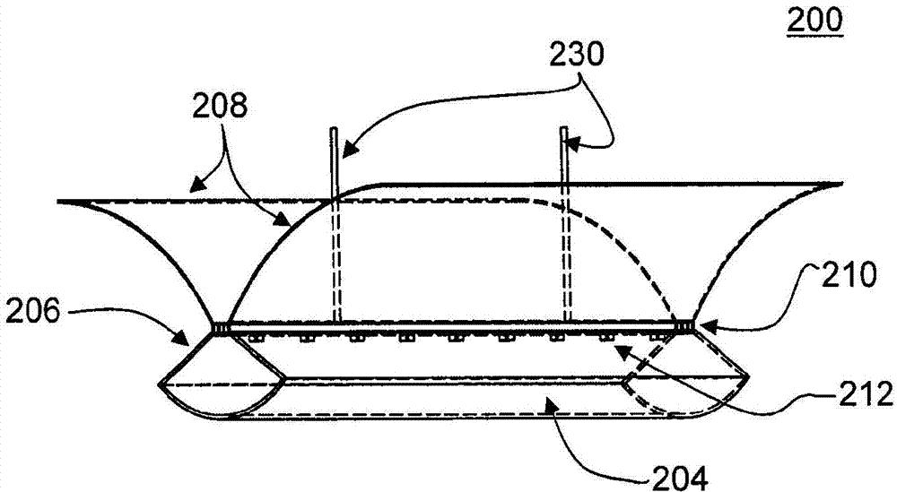
图2(a)是根据本发明的一个实施例的固态光源灯具的图示;Figure 2(a) is an illustration of a solid state light source luminaire according to one embodiment of the present invention;
图2(b)示出了图2中示出的固态光源灯具的剖面图;Fig. 2(b) shows a cross-sectional view of the solid-state light source lamp shown in Fig. 2;
图2(c)图示了示出散热器和固态发光二极管(LED)的图2(b)的放大图;Figure 2(c) illustrates an enlarged view of Figure 2(b) showing the heat sink and solid state light emitting diodes (LEDs);
图3是根据本发明的另一实施例的固态光源灯具的图示;Figure 3 is an illustration of a solid state light source light fixture according to another embodiment of the present invention;
图4(a)至图4(f)示出了本发明的包括一个或更多个光源、波长转换材料、散热器和光学元件的其他实施例的剖面图;Figures 4(a) to 4(f) show cross-sectional views of other embodiments of the present invention comprising one or more light sources, wavelength conversion materials, heat sinks and optical elements;
图5(a)至图5(d)示出了根据本发明的其他实施例的一个或更多个光源、波长转换材料、散热器和光学元件的其他实施例的剖面图;Figures 5(a) to 5(d) show cross-sectional views of other embodiments of one or more light sources, wavelength conversion materials, heat sinks and optical elements according to other embodiments of the present invention;
图6(a)至图6(c)是根据本发明的其他实施例的当与反射器结合时的一个或更多个光源、波长转换材料、散热器和光学元件的剖面图;Figures 6(a) to 6(c) are cross-sectional views of one or more light sources, wavelength converting material, heat sink and optical elements when combined with reflectors according to other embodiments of the present invention;
图7(a)示出了根据本发明的实施例的壁挂式照明灯具;Fig. 7(a) shows a wall-mounted lighting fixture according to an embodiment of the present invention;
图7(b)示出了根据本发明的另一实施例的被配置成悬挂在天花板上的图7(a)的照明灯具;Fig. 7(b) shows the lighting fixture of Fig. 7(a) configured to be suspended from a ceiling according to another embodiment of the present invention;
图7(c)示出了图7(a)和图7(b)中示出的照明灯具的剖面图;Fig. 7(c) shows a cross-sectional view of the lighting fixture shown in Fig. 7(a) and Fig. 7(b);
图7(d)图示了示出散热器、光学元件和固态发光二极管(LED)的图7(c)的放大图;Figure 7(d) illustrates an enlarged view of Figure 7(c) showing the heat sink, optics and solid state light emitting diodes (LEDs);
图8(a)示出了根据本发明的另一实施例的照明灯具;Fig. 8(a) shows a lighting fixture according to another embodiment of the present invention;
图8(b)示出了根据本发明的实施例的在图8(a)中示出的照明灯具的剖面图;Fig. 8(b) shows a cross-sectional view of the lighting fixture shown in Fig. 8(a) according to an embodiment of the present invention;
图8(c)示出了根据本发明的另一实施例的在图8(a)和图8(b)中示出的采用了复合反射器的照明灯具的变型;Fig. 8(c) shows a variation of the lighting fixture shown in Fig. 8(a) and Fig. 8(b) using a composite reflector according to another embodiment of the present invention;
图9(a)至图9(b)图示了根据本发明的另一实施例的采用多个照明灯具的照明系统;Figures 9(a) to 9(b) illustrate a lighting system employing multiple lighting fixtures according to another embodiment of the present invention;
图10(a)图示了与图2(a)中示出的照明灯具类似但是不具有反射器的灯具;以及Figure 10(a) illustrates a lighting fixture similar to that shown in Figure 2(a) but without a reflector; and
图10(b)图示了射线追踪计算机模拟的结果,其示出图10(a)中示出的照明灯具的光输出。Figure 10(b) illustrates the results of a ray tracing computer simulation showing the light output of the lighting fixture shown in Figure 10(a).
具体实施方式 Detailed ways
虽然本文中参考具体的实施例描述和说明了本发明,但是本发明不是意在限制于所示出的细节。更确切地说,在不偏离本发明的前提下并且在权利要求的等同方案的范围内,可以详细地进行各种修改。Although the invention is described and illustrated herein with reference to particular embodiments, the invention is not intended to be limited to the details shown. Rather, various modifications may be made in detail without departing from the invention and within the scope of equivalents of the claims.
在第7,750,359号美国专利中,本发明的发明人之前已经发现了波长转换材料的以下用途:产生具有期望的色度值和发光功效的宽带宽光,同时增加显色指数(CRI)并且降低输出光的相关色温(CCT),从而提高了器件的效率。在第WO 2010/144572号国际公开中,本发明的发明人发现并且公开了通过将波长转换材料移动为远离光源)而获得的益处。通过将波长转换材料移动为远离光源,能够提取更多的经转换的光以及能够提高光器件的功效。采用与光源相邻和/或与光源集成在一起的散热器,获得了附加的益处。这种产生光的方法被描述为散射光子提取(SPE)技术。发现SPE技术增加光产量,改进散热,从而导致延长的光器件耐用性和寿命。这些参考文献的全部内容通过引用合并于此,其中,这些参考文献采用基于SSL的灯泡中的SPE技术作为白炽灯的替代灯泡。In U.S. Patent No. 7,750,359, the inventors of the present invention have previously discovered the use of wavelength conversion materials for producing broad bandwidth light with desired chromaticity values and luminous efficacy while increasing the color rendering index (CRI) and reducing output Correlated color temperature (CCT) of light, thus improving the efficiency of the device. In International Publication No. WO 2010/144572, the inventors of the present invention discovered and disclosed the benefits obtained by moving the wavelength converting material away from the light source). By moving the wavelength converting material away from the light source, more converted light can be extracted and the efficacy of the optical device can be improved. Additional benefits are obtained by using a heat sink adjacent to and/or integrated with the light source. This method of generating light is described as the Scattered Photon Extraction (SPE) technique. SPE technology was found to increase light yield and improve heat dissipation, resulting in extended optical device durability and lifetime. The entire contents of these references employing SPE technology in SSL-based bulbs as replacement bulbs for incandescent bulbs are hereby incorporated by reference in their entirety.
本发明人现在已发现了:可以使用SPE技术来生产高效的照明灯具和照明系统。当与传统的光源相比时,已发现为一般照明应用采用发光二极管(LED)芯片的现有灯具具有更低的发光输出。为了克服该缺陷,现有的基于LED的灯具已利用LED阵列来实现目标表面上所需的光水平。因此,现有的方法也导致了成本的增加、更高的能耗和附加的热处理问题等缺点。本发明的照明灯具利用SPE技术并且可选地利用结构化的光学器件,本发明的照明灯具能够使用更少的LED和更少的电能来产生增加的光发射。本发明的照明灯具还潜在地减小了制造和操作成本。The inventors have now discovered that efficient lighting fixtures and lighting systems can be produced using SPE technology. Existing luminaires employing light emitting diode (LED) chips for general lighting applications have been found to have lower luminous output when compared to conventional light sources. To overcome this drawback, existing LED-based luminaires have utilized arrays of LEDs to achieve the desired light level on the target surface. Therefore, the existing methods also lead to disadvantages such as increased cost, higher energy consumption and additional heat treatment issues. Utilizing SPE technology and optionally structured optics, the lighting fixture of the present invention is capable of producing increased light emission using fewer LEDs and less electrical power. The lighting fixtures of the present invention also potentially reduce manufacturing and operating costs.
本发明通过使用SPE技术解决了这些问题,SPE技术将光源布置在远离波长转换材料的地点。可在光源与波长转换材料之间布置一个或更多个光学元件。另外,可以以各种配置来使用散热器和反射器。光源可以是至少一个半导体发光二极管,例如发光二极管(LED)、激光二极管(LD)或共振腔LED(RCLED)。本发明的实施例可以使用单个SSL源(例如单个LED),或者可以包括多个SSL源(即,阵列中的多个LED)作为光源。如本领域中已知的,可以使用许多不同类型的LED作为光源。例如,当将阵列用作光源时,该阵列可以包括相同或不同类型的一个或更多个LED。可以选择光源以提高能效,控制发射光的颜色质量,或出于许多其他的理由,例如美观性。光源可以耦接至散热器,其中该散热器的至少一部分向环境开放以促进散热。散热器用作光源的散热元件,使得热能够远离光源。散热器还可以向光源提供机械支承。例如,散热器可以基本上附连到光学元件并且耦接到位于光学元件内的光源。该耦合将光源有效地保持在光学元件内。另外,散热器可以基本上附连至一个或更多个反射器。本发明的这些结构特征使得基于SSL的照明灯具能够具有非常高的发光功效值,并且产生类似于或大于传统照明灯具(诸如荧光或白炽照明灯具)的光水平。本发明的配置和对SPE技术的使用还延长了基于SSL的光源的寿命持久性。The present invention solves these problems by using SPE technology, which places the light source at a location remote from the wavelength converting material. One or more optical elements may be arranged between the light source and the wavelength converting material. Additionally, heat sinks and reflectors can be used in various configurations. The light source may be at least one semiconductor light emitting diode, such as a light emitting diode (LED), a laser diode (LD) or a resonant cavity LED (RCLED). Embodiments of the invention may use a single SSL source (eg, a single LED), or may include multiple SSL sources (ie, multiple LEDs in an array) as a light source. As known in the art, many different types of LEDs can be used as light sources. For example, when an array is used as a light source, the array may comprise one or more LEDs of the same or different type. Light sources can be selected to improve energy efficiency, to control the color quality of emitted light, or for many other reasons, such as aesthetics. The light source may be coupled to a heat sink, wherein at least a portion of the heat sink is open to the environment to facilitate heat dissipation. The heat sink acts as a heat dissipation element for the light source, enabling heat to be kept away from the light source. The heat sink can also provide mechanical support to the light source. For example, a heat sink may be substantially attached to the optical element and coupled to a light source located within the optical element. This coupling effectively keeps the light source within the optical element. Additionally, the heat sink may be substantially attached to one or more reflectors. These structural features of the present invention enable SSL-based lighting fixtures to have very high luminous efficacy values and produce light levels similar to or greater than conventional lighting fixtures such as fluorescent or incandescent lighting fixtures. The configuration of the present invention and use of SPE technology also extends the lifetime durability of SSL-based light sources.
波长转换材料的使用帮助产生以下光:该光在美观性上类似于由传统灯具(例如采用白炽A灯的灯具)产生的光。如上所述,本发明的波长转换材料可以由适合于吸收一个光谱区中的辐射和发射另一个光谱区中的辐射的一个或更多个材料组成,并且这些材料可以是下转换或上转换材料。如此,本发明的实施例可以合并下转换的波长转换材料、上转换的波长转换材料或两者。应当理解,术语“下转换(down conversion)”、“下转换的(down converting)”和“下转换的(down converted)”指的是适合于吸收一个光谱区中的辐射并且发射另一个光谱区中的辐射的材料。从而,术语“下转换材料”被定义为以下材料:这些材料可以通过其组分吸收一个光谱区中的辐射并且发射另一个光谱区中的辐射。The use of wavelength converting materials helps produce light that is aesthetically similar to light produced by conventional light fixtures, such as those employing incandescent A lamps. As noted above, the wavelength converting materials of the present invention may consist of one or more materials suitable for absorbing radiation in one spectral region and emitting radiation in another spectral region, and these materials may be down-converting or up-converting materials . As such, embodiments of the present invention may incorporate down-converting wavelength-converting materials, up-converting wavelength-converting materials, or both. It should be understood that the terms "down conversion", "down converting" and "down converted" refer to materials suitable for absorbing radiation in one spectral region and emitting in another spectral region Radiation in materials. Thus, the term "down-converting material" is defined as a material which, through its constituents, can absorb radiation in one spectral region and emit radiation in another spectral region.
当从光源发射的光到达波长转换材料时,波长转换材料吸收该波长的光并且发射经转换的光。例如,当波长转换材料包括下转换材料时,该下转换材料吸收短波长光并且发射下转换的光。所发射的下转换的光可以沿着所有方向传播(被称为朗伯(Lambertian)发光体),因此,下转换的光的一部分向上传播,而另一部分向下传播。从下转换材料向上(或向外)离去的光是该光的向前传送部分,而朝着光源向下回来的光是向后传送部分。下面将参考图1对此作进一步说明。When light emitted from a light source reaches the wavelength converting material, the wavelength converting material absorbs light of that wavelength and emits converted light. For example, when the wavelength converting material includes a down converting material, the down converting material absorbs short wavelength light and emits down converted light. The emitted down-converted light can travel in all directions (referred to as a Lambertian illuminant), so part of the down-converted light travels up and the other part travels down. Light going up (or out) from the down-converting material is the forward-transported portion of that light, while light coming back down toward the light source is the backward-transmitted portion. This will be further explained below with reference to FIG. 1 .
本发明的灯具实现与SPE技术相关联的远程波长转换概念。在采用远程下转换材料的系统中,朝着远离光源布置的下转换材料发射来自光源的短波长辐射能量。命中下转换材料的辐射能量的至少一部分被下转换为更长波长的辐射,当这两个辐射混合时,产生与由传统灯具产生的光类似的白光。波长转换材料可以由适合于吸收一个光谱区中的辐射并且发射另一个光谱区中的辐射的一个或更多个下转换材料组成。波长转换材料可以混合在一起或作为单独层使用。多个波长转换材料能够将从光源发射的波长转换至相同或不同的光谱区。从而,波长转换材料可以包括一个或更多个下转换材料、上转换材料或两者,可以对其进行选择以产生期望的光输出和显色属性。The luminaire of the present invention implements the concept of remote wavelength conversion associated with SPE technology. In systems employing remote down-converting materials, short-wavelength radiant energy from the light source is emitted toward the down-converting material disposed remotely from the light source. At least a portion of the radiant energy hitting the down-converting material is down-converted to longer wavelength radiation which, when mixed, produces white light similar to that produced by conventional luminaires. The wavelength converting material may consist of one or more down converting materials adapted to absorb radiation in one spectral region and emit radiation in another spectral region. The wavelength converting materials can be mixed together or used as separate layers. Multiple wavelength converting materials are capable of converting the wavelength emitted from the light source to the same or different spectral regions. Thus, the wavelength converting material may include one or more down converting materials, up converting materials, or both, which may be selected to produce desired light output and color rendering properties.
图1示出了根据本发明的示例性实施例的使用固态发光二极管(LED)102和波长转换材料104来产生可见光的方法。如所示出的,从LED 102发射的光辐射100击中波长转换材料104。从LED 102发射的光辐射100中的一些被波长转换材料104反射为向后传递的未经转换的辐射106。从LED 102发射的光辐射100的其它部分被波长转换材料104转换并且被向后发射为向后传递的转换的辐射118。从LED 102发射的光辐射100中的一些穿过波长转换材料104作为向前传递的未经转换的辐射108,而一些辐射穿过波长转换材料104作为向前传递的转换辐射114。此外,波长转换材料104可以发射向前散射的转换辐射116和向后散射的转换辐射120。向后散射的转换辐射120和向后传递的转换辐射118总体被看作向后传递的波长转换辐射112,而向前散射的转换辐射116和向前传递的转换辐射114总体被看作向前传递的波长转换辐射110。将光源布置成远离波长转换材料的SPE技术的使用使得能够改进所反射的未经转换的光子106和所传递的未经转换的光子108、被波长转换材料104转换的所反射的转换光子118和所传递的转换光子114以及向前散射的转换辐射116和向后散射的转换辐射120的提取。FIG. 1 illustrates a method of generating visible light using a solid state light emitting diode (LED) 102 and a
光学元件可以占据将LED与波长转换材料分隔开的间隔。在一些实施例中,光学元件可以在一端附连至LED光源并且在另一端附连至波长转换材料。光学元件可以采用任意的三维几何形状,例如球形、抛物形、圆锥形和椭圆形。光学元件还可以被描述为具有从圆形、三角形、六边形、梯形、半圆形和椭圆形等中选择的剖面形状。光学元件可以是基本上透明并且透光的介质,例如空气、玻璃或丙烯酸树脂。可以使用一个或更多个反射器来接收和反射由光源发射并且被下转换材料下转换的光(即,传递的光)。反射器可以采用任意的几何形状,例如球形、抛物形、圆锥形和椭圆形,并且可以由本领域中已知的各种反射面组成。另外,反射器可以是单个单元或复合单元,其中复合单元包括各自具有其自己的几何形状、透射率和材料组分的多个反射面。例如,反射器可以是铝、具有蒸镀铝反射层的塑料、或其他任意类型的反射面。反射器被布置成反射下转换的光,并且可以与下转换材料相分离或相邻。在一些实施例中,多于一个的反射器可以被单独地使用,或被用作具有多个几何构造的复合反射器的一部分。The optical element may occupy the space separating the LED from the wavelength converting material. In some embodiments, the optical element may be attached to the LED light source at one end and to the wavelength converting material at the other end. Optical elements can take any three-dimensional geometry, such as spherical, parabolic, conical, and elliptical. Optical elements may also be described as having a cross-sectional shape selected from circular, triangular, hexagonal, trapezoidal, semicircular, and elliptical, among others. The optical element may be a substantially transparent and light transmitting medium such as air, glass or acrylic. One or more reflectors may be used to receive and reflect light emitted by the light source and down-converted by the down-converting material (ie, transmitted light). The reflector can take any geometric shape, such as spherical, parabolic, conical, and elliptical, and can be composed of various reflective surfaces known in the art. Additionally, the reflector may be a single unit or a composite unit, where the composite unit includes multiple reflective surfaces each having its own geometry, transmissivity and material composition. For example, the reflector can be aluminum, plastic with an evaporated aluminum reflective layer, or any other type of reflective surface. The reflector is arranged to reflect the down converted light and may be separate from or adjacent to the down conversion material. In some embodiments, more than one reflector may be used individually, or as part of a composite reflector having multiple geometries.
在本发明的一些实施例中,反射器可以是诸如玻璃的光学元件,其已经被处理成将反射特性赋予该光学元件。例如,反射器可以是其上沉积了或以其它方式施加了薄膜的光学元件。这样的反射器在本领域中被称为分色滤光器、薄膜滤光器或干涉滤光器,并且通常被用来选择性地使小范围颜色的光穿过而反射其他颜色。比较起来,分色镜倾向于用其反射的光的颜色来表征,而不是穿过分色镜的颜色。为了简单起见,由于以该方式处理的反射器可以选择性地并且同时地允许一些光穿过而反射其他光,所以以该方式处理的反射器在本文中被总体上称为“分色反射器”。如本领域中已知的,例如这样的分色反射器可以对于具体的波长、热、光或对于由光源发射的辐射的其他特征是选择性的。本发明的反射器和光学元件可以具有变化的透射度,即,它们可以被选择为允许或反射任意范围的辐射。例如,光学元件可以是完全透明的,并且允许所有的光辐射穿过。然而,如本领域普通技术人员所已知的,即使完全透明的光学元件也可能具有一些微量的反射特征(例如,已经发现透明玻璃反射大约4%的光辐射),其被认为是光学元件所固有的。可替代地,光学元件可以是完全反射性的,并且不允许任何光辐射穿过。另外,可以预制本发明的光学元件和反射器,使得它们包含具有特定透射量的一些部分、和允许或反射不同量的光辐射的其他部分。从而,每个光学元件或反射器可以在各处具有相同的透射水平,或者包括具有变化的透射水平的不同部分。可以通过本领域已知的许多手段来实现光学元件的任意范围的透射率。In some embodiments of the invention, the reflector may be an optical element, such as glass, that has been treated to impart reflective properties to the optical element. For example, a reflector may be an optical element on which a thin film is deposited or otherwise applied. Such reflectors are known in the art as dichroic filters, thin film filters, or interference filters, and are often used to selectively pass light of a small range of colors while reflecting other colors. In comparison, dichroic mirrors tend to be characterized by the color of the light they reflect rather than the color that passes through the dichroic mirror. For simplicity, reflectors treated in this manner are generally referred to herein as "dichroic reflectors" since they can selectively and simultaneously allow some light to pass through while reflecting other light. ". Such dichroic reflectors, for example, may be selective for particular wavelengths, heat, light, or for other characteristics of the radiation emitted by the light source, as is known in the art. The reflectors and optical elements of the present invention may have varying degrees of transmission, ie they may be selected to allow or reflect any range of radiation. For example, an optical element may be completely transparent and allow all optical radiation to pass through. However, as is known to those of ordinary skill in the art, even completely transparent optical elements may have some trace reflective features (for example, clear glass has been found to reflect approximately 4% of optical radiation), which is believed to be the result of optical elements. inherent. Alternatively, the optical element may be completely reflective and not allow any light radiation to pass through. In addition, the optical elements and reflectors of the present invention may be prefabricated such that they contain some parts with a certain amount of transmission, and other parts which allow or reflect different amounts of optical radiation. Thus, each optical element or reflector may have the same level of transmission everywhere, or comprise different parts with varying levels of transmission. Any range of transmittance for an optical element can be achieved by a number of means known in the art.
在本发明的至少一个实施例中,使用本领域中已知的常规技术将波长转换材料施加至以及容纳在光学元件或反射器上。在另一个实施例中,将波长转换材料(例如下转换材料)集成到光学元件或反射器中。例如,在丙烯酸树脂制造过程期间,可以制造合并有下转换材料(例如磷光体)的丙烯酸树脂光学元件,从而产生集成的下转换光学元件。In at least one embodiment of the invention, the wavelength converting material is applied to and received on the optical element or reflector using conventional techniques known in the art. In another embodiment, a wavelength conversion material (eg a down conversion material) is integrated into the optical element or reflector. For example, during the acrylic manufacturing process, acrylic optical elements can be fabricated that incorporate down-converting materials such as phosphors, resulting in integrated down-converting optical elements.
如上面关于图1所详述的,波长转换材料可以传递、转换或反射光辐射。一些光辐射可以向后朝着光源被反射为未经转换的光辐射。可将经转换的光向前传递或向后传递。另外,一些光可以不经转换(即,未经转换的传送辐射)而传递通过波长转换材料。通过捕获下转换的光的向前传递部分和向后传递部分两者,提高了系统效率。类似地,当使用一个或更多个反射器时,可以调节下转换材料和反射器的位置以确保来自光源的光均匀地冲击下转换材料,以产生均匀的白光并且使得更多的光离开器件。与此同时,将下转换材料布置为远离光源防止了光反馈回到光源中。所以,进一步使光源处的热最小化,从而导致增加的光输出和寿命。与已知技术相比,所有这些结构参数和特征使得能够增加光产量,增强照明效率,以及改进能量利用率。As detailed above with respect to FIG. 1 , the wavelength converting material may transmit, convert or reflect optical radiation. Some of the optical radiation may be reflected back towards the light source as unconverted optical radiation. The converted light can be passed forward or backward. Additionally, some light may pass through the wavelength converting material unconverted (ie, unconverted transmitted radiation). By capturing both the forward and backward pass portions of the down-converted light, system efficiency is increased. Similarly, when using one or more reflectors, the position of the down conversion material and reflectors can be adjusted to ensure that the light from the light source hits the down conversion material evenly to produce uniform white light and allow more light to exit the device . At the same time, arranging the down conversion material away from the light source prevents light from feeding back into the light source. Therefore, heat at the light source is further minimized, resulting in increased light output and lifetime. All these structural parameters and features enable increased light yield, enhanced lighting efficiency, and improved energy utilization compared to known technologies.
本发明的固态发光器件还可以包括本领域中已知的其他部件。例如,SSL器件还可以包括电子驱动器。大多数SSL源是低压直流(DC)源。因此,需要电子驱动器来调节电压和电流以在基于SSL的灯具中使用。可替代地,存在若干交流(AC)SSL源,例如,由韩国首尔的首尔半导体公司以商品名“Acriche”出售的AC-LED。在这些情况下,SSL源(如,LED或LED阵列)可以直接连接至可从电网获得的AC电源。因此,可选地,本发明的实施例可以包括电子驱动器,该电子驱动器的至少一部分位于灯具的底座内,这取决于在基于SSL的灯具中采用的SSL源的类型。本发明还可以包括至少一个电子导体,例如连接导线。电子导体可以布置在光学元件内以耦合灯具底座与光源之间的电流。The solid state light emitting devices of the present invention may also include other components known in the art. For example, SSL devices may also include electronic drivers. Most SSL sources are low voltage direct current (DC) sources. Therefore, electronic drivers are required to regulate voltage and current for use in SSL-based luminaires. Alternatively, there are several alternating current (AC) SSL sources such as AC-LEDs sold under the trade name "Acriche" by Seoul Semiconductor Corporation of Seoul, Korea. In these cases, the SSL source (eg, LED or LED array) can be connected directly to AC power available from the grid. Accordingly, embodiments of the present invention may optionally include an electronic driver at least partly located within the base of the luminaire, depending on the type of SSL source employed in the SSL-based luminaire. The invention may also comprise at least one electrical conductor, such as a connecting wire. Electrical conductors may be arranged within the optical element to couple electrical current between the luminaire base and the light source.
可以以任意布置来使用本发明的灯具。例如,本发明的至少一个实施例是悬挂式灯具或头顶式灯具。在这样的实施例中,灯具可具有一个或更多个悬挂机构,例如悬挂杆、缆绳或法兰。在本发明的另一实施例中,灯具是壁挂式灯具。在这样的实施例中,可以水平地、竖直地或以为实现期望的美观性和光输出所需的任何其他方式来安装灯具。在其它实施例中,本发明是包括一个或更多个灯具的系统。在这样的实施例中,该灯系统可以包括许多类似的灯具或不同的灯具。本发明的一个或更多个实施例可以被配置成悬挂式、壁挂式或两者。例如,本发明的一些实施例可以被配置成充当头顶悬挂式灯具或充当壁挂式灯具,其具有悬挂装置和能够适应任一配置的其他部件。另外,取决于照明区域中期望的照明量以及其他因素(例如视觉美观性),本发明的实施例可以安装有指向或远离照明区域的光学元件或反射器。根据下面描述的图可以更好地理解这些实施例。The luminaires of the present invention may be used in any arrangement. For example, at least one embodiment of the present invention is a pendant light fixture or an overhead light fixture. In such embodiments, the light fixture may have one or more suspension mechanisms, such as suspension rods, cables, or flanges. In another embodiment of the invention, the luminaire is a wall-mounted luminaire. In such embodiments, the light fixture may be mounted horizontally, vertically, or in any other manner required to achieve the desired aesthetics and light output. In other embodiments, the invention is a system comprising one or more light fixtures. In such an embodiment, the light system may include many similar light fixtures or different light fixtures. One or more embodiments of the present invention may be configured to be hung, wall-mounted, or both. For example, some embodiments of the present invention may be configured to function as an overhead-mounted light fixture or as a wall-mounted light fixture with suspension and other components that can accommodate either configuration. Additionally, embodiments of the invention may be mounted with optics or reflectors directed toward or away from the illuminated area, depending on the desired amount of illumination in the illuminated area, as well as other factors such as visual aesthetics. These embodiments can be better understood with reference to the figures described below.
图2(a)是根据本发明的一个实施例的悬挂式或头顶式固态光源灯具的图示。图2(a)中示出的悬挂式灯具被认为是挤压式灯具配置,因为该灯具的剖面轮廓沿着其水平轴线基本上是均匀的。术语“挤压式”不是旨在将本发明的本实施例限制于任何具体的制造工艺(例如挤压工艺)或其结果。替代地,可以通过许多已知的方法来制造本发明的挤压式SPE灯具及其各个部件。术语“挤压式”在本文中用来替代地指代具有固定的剖面轮廓但是具有细长的侧面的SPE灯具的配置。当然,其他实施例可以沿着水平轴线示出剖面轮廓的变化。如所示出的,灯具的光源包括LED阵列212中的多个发光体。LED阵列212布置在具有远离光源的凹面的三角形剖面光学元件206的角度内。LED阵列向下朝着光学元件的凹面发射光辐射,其中,在光学元件的凹面上沉积波长转换材料204。灯具还包括两个抛物形反射器208,其布置在光学元件206和LED阵列212上方。反射器将由LED阵列发射的并且被下转换的以及朝着反射器被向后传递的光反射到期望的环境,即照明区域。在图2(b)中对该实施例做了进一步的详细描述,图2(b)图示了图2(a)中示出的固态光源灯具的剖面图。如所示出的,LED阵列(其在该视图中被示出为一个LED发光体202)向下朝着包括下转换材料的波长转换材料204发射光辐射。波长转换材料204沉积在三角形剖面光学元件206的凹面上。如果对于特定灯具配置、光效率和输出来说是需要的,则在光学元件的其他壁上也可以涂覆波长转换材料。所发射的光辐射214中的一些被下转换并且被向前传递为穿过光学元件206的凹面的向前传递的光220。所发射的光辐射214中的一些被下转换并且被向后传递为穿过光学元件206的侧壁朝向反射器208的向后传递的光222,其中经转换的光辐射被反射。在图示的实施例中,附图标记214、220和222表示光束,而不是物理元件,也不是本发明要求保护的部件。Fig. 2(a) is an illustration of a suspended or overhead solid state light source light fixture according to one embodiment of the present invention. The suspended luminaire shown in Figure 2(a) is considered an extruded luminaire configuration because the cross-sectional profile of the luminaire is substantially uniform along its horizontal axis. The term "extrusion" is not intended to limit this embodiment of the invention to any particular manufacturing process (eg, extrusion process) or result thereof. Alternatively, the extruded SPE luminaire of the present invention and its individual components can be manufactured by a number of known methods. The term "extruded" is used herein to refer alternatively to a configuration of an SPE luminaire that has a fixed cross-sectional profile but has elongated sides. Of course, other embodiments may show variations in the cross-sectional profile along the horizontal axis. As shown, the light source of the light fixture includes a plurality of light emitters in an
撞击在反射器上的光射线的方向期望与穿过下转换层传送的光射线的方向相同。因此,灯具的总的光输出可以是穿过下转换材料传送的光与向后传递的射线的组合。然而,取决于反射器的尺寸、几何形状以及与光学元件的距离,来自波长转换材料的向后传递的射线可能没有命中反射器而撞击在天花板或墙壁上。这样的向上的射线对于间接-直接型灯具将是有用的,其将导致房间的上部空间的亮度增加。The direction of the light rays impinging on the reflector is desirably the same as the direction of the light rays traveling through the down conversion layer. Thus, the total light output of a luminaire may be a combination of light transmitted through the down conversion material and rays transmitted backwards. However, depending on the size, geometry and distance of the reflector from the optical element, the backward passing rays from the wavelength converting material may miss the reflector and impinge on the ceiling or wall. Such an upward ray would be useful for an indirect-direct type luminaire, which would result in an increased brightness of the upper space of the room.
在本实施例中,沉积在光学元件的凹面上的波长转换材料可以被光学元件包围以防止有害的灰尘堆积,其中随着时间的推移,这些有害的灰尘堆积可能减少灯具的总的光输出。如上所述,波长转换材料是吸收一个光谱区中的辐射并且发射另一个光谱区中的辐射的材料。在示例性实施例中,波长转换材料可以包括单一的波长转换材料。在可替代的实施例中,波长转换材料可以包括多于一个的波长转换材料。多个波长转换材料能够将从发光体发射的波长转换到相同或不同的光谱区。在示例性或可替代的实施例中,波长转换材料可以包括:一个或更多个磷光体,例如掺杂有铈的钇铝石榴石(YAG:Ce)、掺杂有铕的硫化锶(SrS:Eu)、掺杂有铕的YAG:Ce磷光体;YAG:Ce磷光体加硒化镉(CdSe);或从包括铅(Pb)和硅(Si)的其他材料产生的其他类型的量子点;等等。在可替代的实施例中,磷光体层可以包括其他磷光体、量子点、量子点晶体、量子点纳米晶体或其他下转换材料。波长转换材料可以是下转换晶体,而不是与粘合介质混合的粉末材料。波长转换材料层可以包括诸如微球体的附加的散射颗粒,以改进不同波长的光的混合。在可替代的实施例中,波长转换材料可以由多个连续或离散的子层组成,每个子层包括不同的波长转换材料。例如,可以通过安装、涂覆、沉积、模板印刷、屏幕印刷和任何其他适合的技术来形成波长转换材料。波长转换材料可以部分地形成在光学元件的一个壁上。本申请中公开的所有实施例可以使用本文中描述的磷光体中的任一个。In this embodiment, the wavelength converting material deposited on the concave surface of the optical element may be surrounded by the optical element to prevent unwanted dust buildup which may reduce the overall light output of the luminaire over time. As mentioned above, wavelength converting materials are materials that absorb radiation in one spectral region and emit radiation in another spectral region. In exemplary embodiments, the wavelength converting material may include a single wavelength converting material. In alternative embodiments, the wavelength converting material may comprise more than one wavelength converting material. Multiple wavelength converting materials are capable of converting the wavelength emitted from the light emitter to the same or different spectral regions. In an exemplary or alternative embodiment, the wavelength conversion material may include: one or more phosphors such as cerium-doped yttrium aluminum garnet (YAG:Ce), europium-doped strontium sulfide (SrS :Eu), YAG:Ce phosphors doped with europium; YAG:Ce phosphors plus cadmium selenide (CdSe); or other types of quantum dots produced from other materials including lead (Pb) and silicon (Si) ;etc. In alternative embodiments, the phosphor layer may include other phosphors, quantum dots, quantum dot crystals, quantum dot nanocrystals, or other down conversion materials. The wavelength conversion material may be a down conversion crystal instead of a powder material mixed with a binding medium. The layer of wavelength converting material may include additional scattering particles, such as microspheres, to improve mixing of light of different wavelengths. In alternative embodiments, the wavelength converting material may consist of a plurality of continuous or discrete sub-layers, each sub-layer comprising a different wavelength converting material. For example, wavelength converting materials may be formed by mounting, coating, deposition, stencil printing, screen printing, and any other suitable technique. The wavelength converting material may be partially formed on one wall of the optical element. All of the embodiments disclosed in this application may use any of the phosphors described herein.
通过使用散热器可以实现附加的益处。图2(a)至图2(c)中示出的实施例是悬挂式或头顶式灯具,其通过一个或更多个悬挂机构附连至表面。例如,可以使用吊线或吊杆(中空或实心)来悬挂灯具。悬挂机构还可以包括电源线、控制线或需要包含在灯具中的其他方面。灯具的电源线和控制线可以与吊线连接在一起或位于杆面。Additional benefits can be realized through the use of heat sinks. The embodiments shown in Figures 2(a)-2(c) are suspended or overhead light fixtures that are attached to a surface by one or more suspension mechanisms. For example, hanging wires or rods (hollow or solid) can be used to hang light fixtures. The suspension mechanism can also include power wires, control wires, or other aspects that need to be included in the light fixture. The power and control wires of the luminaire can be connected with the suspension wire or located on the pole face.
图2(c)图示了示出散热器210和LED发光体202的图2(b)的放大图。散热器210被示出为附连至LED发光体202的底部,因为本实施例被示为悬挂式或头顶式灯具,所以这实际上表示散热器210围绕LED发光体202或位于LED发光体202上方。散热器210的至少一部分位于由光学元件206创建的罩的外部。散热器可以包括一系列翅片。可替代地或附加地,散热器可以包括如下网:该网从散热器210延伸并且围绕LED发光体202与光学元件的凹面之间的光学元件206的外表面的至少一部分。散热器210可以由本领域中已知的各种散热材料制造而成,例如铝、铜和碳纤维。散热器可以涂上颜色,例如涂上白色以增强或改变材料的散热性能。散热器210的至少一部分位于光学元件206的外部,而散热器210耦接至内部的LED发光体202。例如,这可以在光学元件中的与光学元件的凹面基本上相对的一端上的临界点处实现。该耦接有效地将LED发光体202基本上保持在光学元件206内,同时还将光学元件206密封闭合。一旦完成组装,光学元件206的内部可以是实心的、真空的、或者可以填充有空气或惰性气体。FIG. 2( c ) illustrates an enlarged view of FIG. 2( b ) showing
图3是根据本发明的另一实施例的固态光源灯具的图示。由于这样的灯具仅通过一个悬挂机构悬挂,所以该灯具可以被认为是悬吊灯具。因为在灯具围绕其垂直轴环绕地旋转时灯具的剖面轮廓基本上是均匀的,所以图3中示出的悬吊灯具也被认为是旋转式灯具配置。当然,在灯具围绕垂直轴旋转时,其他实施例可以示出剖面轮廓的变化。在图3所示的实施例中,LED阵列312被布置为向下朝着沉积在圆锥形透射光学元件306上的远端波长转换材料304发射光辐射。在LED阵列312和光学元件306上面翻转地附连圆锥形反射器308,从而为完整的灯具300提供沙漏外形。在反射器308与光学元件306之间,散热器310邻近于或附连到LED阵列312。在该实施例中,悬吊型灯具300通过单一的悬挂机构330悬挂在照明位置。散热器310可以用来机械地支承辐射发光源(在本实施例中为LED阵列312),并且用于散热目的。3 is an illustration of a solid state light source light fixture according to another embodiment of the present invention. Since such a luminaire is suspended by only one suspension mechanism, the luminaire can be considered a pendant luminaire. Since the cross-sectional profile of the luminaire is substantially uniform as the luminaire is rotated around its vertical axis, the pendant luminaire shown in Figure 3 is also considered a rotating luminaire configuration. Of course, other embodiments may show a change in cross-sectional profile as the luminaire is rotated about a vertical axis. In the embodiment shown in FIG. 3 ,
图4(a)至图4(f)图示根据本发明的其他实施例的以一个或更多个光源、波长转换材料、散热器、光学元件和反射器为特征的各种灯具配置的剖面图。如所示出的,光源可以是布置在反射器与光学元件之间的一个发光体。图4(a)示出了使用一个发光体将光投向沉淀在三角形光学元件上或与三角形光学元件集成在一起的波长转换材料的实施例。图4(a)和图4(f)示出了波长转换材料可以沉积在光学元件的一个或更多个表面上或与光学元件的一个或更多个表面集成在一起的本发明的实施例。如图4(a)至图4(f)中示出的以及上面所说明的,光学元件可以采用许多其他形状。在图4(a)至图4(f)示出的灯具实施例中的每个中,由光源发射的一些光辐射可以向后朝着光源被反射为未经转换的光辐射。经转换的光可以向前传递或向后传递。另外,一些光可以不经转换而穿过波长转换材料传递(即,未经转换的传送辐射)。通过捕获下转换光的向前传递部分和向后传递部分两者,可以提高系统效率。类似地,当使用一个或更多个反射器时,可以调节下转换材料和反射器的位置以确保来自光源的光均匀地撞击下转换材料,以产生均匀的白光并且使得更多的光离开器件。与此同时,将下转换材料布置为远离光源防止了光向后反馈回到光源中。因此,进一步使光源处的热最小化,并且导致增加的光输出和寿命。可以以任何方式来配置光学元件和反射器的形状、以及发光体的位置和数量,以与已知技术相比实现增加的光产量、增强的光效率以及提高的能量利用率。Figures 4(a)-4(f) illustrate cross-sections of various luminaire configurations featuring one or more light sources, wavelength converting material, heat sinks, optical elements, and reflectors, according to other embodiments of the invention picture. As shown, the light source may be a light emitter disposed between the reflector and the optical element. Figure 4(a) shows an embodiment of using one light emitter to direct light to a wavelength conversion material deposited on or integrated with a triangular optic. Figures 4(a) and 4(f) illustrate embodiments of the present invention where the wavelength conversion material may be deposited on or integrated with one or more surfaces of the optical element . As shown in Figures 4(a)-4(f) and explained above, the optical element may take many other shapes. In each of the luminaire embodiments shown in Figures 4(a) to 4(f), some of the light radiation emitted by the light source may be reflected back towards the light source as unconverted light radiation. The converted light can be passed forward or backward. Additionally, some light may pass through the wavelength converting material without conversion (ie, unconverted transmitted radiation). By capturing both the forward and backward pass portions of the down-converted light, system efficiency can be increased. Similarly, when using one or more reflectors, the position of the down conversion material and reflectors can be adjusted to ensure that the light from the light source hits the down conversion material evenly to produce uniform white light and allow more light to exit the device . At the same time, arranging the down conversion material away from the light source prevents light from feeding back into the light source. Thus, heat at the light source is further minimized and results in increased light output and lifetime. The shape of the optical elements and reflectors, as well as the location and number of light emitters may be configured in any manner to achieve increased light yield, enhanced light efficiency and improved energy utilization compared to known techniques.
图5(a)至图5(c)图示根据本发明其他实施例的以一个或更多个光源、波长转换材料、散热器、光学元件和反射器为特征的各种灯具配置的剖面图。如所示出的,可以使用大量的光源。例如,图5(a)至图5(d)示出了各自具有多个发光体502的实施例。图5(a)示出了使用两个发光体502将光投向沉积在五边形光学元件上或与五边形光学元件集成在一起的波长转换材料的实施例。发光体502附连至散热器510。发光体502布置在与光学元件506的沉积有波长转换材料504的表面基本上相对的光学元件506的一个或更多个表面上。在该配置中,发光体502布置在波长转换材料504与反射器508之间。发光体502朝着波长转换材料504发射光辐射,其中,至少一些光辐射被转换并且沿着发光体的方向向后传递。反射器508被布置成将向后传递的经转换的光辐射中的至少一部分反射到期望的环境,即照明区域。在图5(a)所示的配置中,除了向前传递的经转换的光辐射之外,反射器还反射向后传递的经转换的光辐射,以对期望区进行照明。Figures 5(a)-5(c) illustrate cross-sectional views of various luminaire configurations featuring one or more light sources, wavelength converting materials, heat sinks, optical elements, and reflectors, according to other embodiments of the invention . As shown, a large number of light sources can be used. For example, FIGS. 5( a )- 5( d ) illustrate embodiments each having a plurality of
在图5(b)中将图5(a)所示的五边形光学元件翻转。图5(c)和图5(d)示出了根据本发明的至少一个实施例的灯具的其它配置。图5(c)和图5(d)所示的光学元件也可以被看作五边形光学元件,但是具有内凹的三角形轮廓而不是外突的三角形轮廓。在图5(a)至图5(d)所示的灯具实施例的每个中,使用了多个发光体502,其中每个发光体都附连有散热器510。图5(b)示出了波长转换材料504沉积在光学元件506的一个表面上或与光学元件506的一个表面集成在一起的实施例,而图5(c)示出了波长转换材料504沉积在光学元件506的多个表面上或与光学元件506的多个表面集成在一起的实施例。在图5(d)所示的实施例中,波长转换材料504沉积在与具有发光体502的表面垂直的光学元件506的单一表面上。在图5(a)至图5(d)所示的实施例中,由发光体502发射的一些光辐射可以向后朝着光源被反射为未经转换的光辐射。经转换的光可以向前传递或向后传递。另外,一些光可以不经转换而穿过波长转换材料传递(即,未经转换的传送辐射)。在图5(b)和图5(c)所示的实施例中,波长转换材料沉积在光源与反射器之间的光学元件的一个或更多个表面上。在这样的实施例中,反射器捕获并且反射下转换光辐射的向前传递部分。允许下转换光辐射的向后传递部分穿过光学元件的透射表面。通过捕获下转换光的向前传递部分和向后传递部分两者,可以提高系统效率。如上所述,可以以任何方式来配置光学元件和反射器的形状、以及发光体的位置和数量,以与已知技术相比实现增加的光产量、增强的照明效率和提高的能量利用率。The pentagonal optical element shown in Figure 5(a) is flipped over in Figure 5(b). Figures 5(c) and 5(d) illustrate other configurations of light fixtures according to at least one embodiment of the present invention. The optics shown in Figures 5(c) and 5(d) can also be viewed as pentagonal optics, but with a concave triangular profile instead of a protruding triangular profile. In each of the luminaire embodiments shown in Figures 5(a) to 5(d), a plurality of
本发明的灯具可以合并具有无数形状和尺寸的一个或更多个反射器。图6(a)至图6(c)图示根据本发明的其他实施例的具有不同形状的反射器的各种灯具的剖面视图。这样的反射器既可以与例如图2(a)以及图6(a)至图6(c)所示的挤压型灯具一起使用,也可以与图3所示的旋转型灯具一起使用。除了挤压式或旋转式灯具以外,本发明的SPE灯具的光学元件还可以具有多个边。例如,光学元件可以具有正方形、矩形、梯形、五边形、六边形或八边形等结构形状。具有这些结构形状中的任一个的光学元件可以合并到本发明的实施例中的任一个中。Luminaires of the present invention may incorporate one or more reflectors of myriad shapes and sizes. 6( a ) to 6 ( c ) illustrate cross-sectional views of various luminaires with reflectors of different shapes according to other embodiments of the present invention. Such reflectors can be used both with extruded luminaires such as those shown in Figs. 2(a) and 6(a)-6(c), and with swivel luminaires as shown in Fig. In addition to squeeze or swivel luminaires, the optical elements of the SPE luminaires of the present invention may also have multiple sides. For example, the optical element may have a structural shape such as a square, a rectangle, a trapezoid, a pentagon, a hexagon, or an octagon. Optical elements having any of these structural shapes may be incorporated into any of the embodiments of the present invention.
图7(a)和图7(b)图示使用以发光体阵列712为特征的SPE技术的本发明的其它示例性实施例。图7(a)和图7(b)分别图示当用作壁灯和用作悬挂的吊灯的实施例。这里,安装灯具的墙壁或天花板可以起反射器的作用。图7(c)示出了针对两个实施例的剖面图。如所示出的,SPE灯具包括沉积有波长转换材料层704的光学元件706。可以使用具有高透射量(即,低反射涂层)的反射器708(例如透明的盖),来控制灯具的输出光谱以及提供期望的美观性。图7(d)图示图7(c)的放大图,其示出散热器、光学元件和固态发光二极管(LED)。在散热器上可以安装LED或LED阵列。可以使用机械部件或悬挂机构来支承散热器并且将灯具附连到墙壁或天花板上。7( a ) and 7( b ) illustrate other exemplary embodiments of the present invention using SPE technology featuring an
图8(a)图示使用SPE技术的本发明的又一示例性实施例。图8(a)图示使用固态发光体和远端波长转换材料的另一高效灯具。图8(b)是图8(a)中的灯具的剖面图。如所示出的,灯具包括远离光辐射发光体802的波长转换材料804。发光体802和波长转换材料804两者附连至光学元件806或与光学元件806集成在一起。波长转换材料804可以是磷光体。可以使用反射器808来控制输出光束分布,并且提高光束的颜色均匀性。如上所说明的,散热器810可以用于安装发光体802以及用于散热。使用悬挂机构830将波长转换材料804悬挂在由光学元件806创建的罩内发光体802的上方。悬挂机构830还可以用于将SPE灯具安装到墙壁或天花板上。出于包括改进光束控制、光效率和美观性的多个理由,多个反射器可以单独使用、或作为复合反射面一起使用。图8(c)图示合并复合反射器808的实施例的剖面图。图8(a)至图8(c)所示的SPE灯具的典型应用是嵌入式筒灯、悬吊式筒等和轨道筒灯。Figure 8(a) illustrates yet another exemplary embodiment of the present invention using SPE technology. Figure 8(a) illustrates another high efficiency luminaire using solid state light emitters and remote wavelength converting material. Fig. 8(b) is a cross-sectional view of the lamp in Fig. 8(a). As shown, the light fixture includes a
图9(a)和图9(b)图示包括多个SPE灯具作为SPE灯系统或组件的本发明的其它实施例。SPE灯系统可以由一个或更多个SPE灯具组成,如图2至图8中所示的那些SPE灯具。该SPE灯系统内的SPE灯具可以相同或不同。如本领域普通技术人员可以想到的,可以经由光学元件、反射器、散热器、悬挂机构或经由其他已知的部件来连接各个SPE灯具。Figures 9(a) and 9(b) illustrate other embodiments of the invention comprising a plurality of SPE luminaires as a SPE lamp system or assembly. A SPE lamp system may consist of one or more SPE lamps, such as those shown in FIGS. 2-8 . The SPE lamps within the SPE lamp system can be the same or different. As would occur to one of ordinary skill in the art, the individual SPE luminaires may be connected via optical elements, reflectors, heat sinks, suspension mechanisms, or via other known components.
来自LED光源和加入灯具中的其他必需的电子元件的热量限制了能够以可靠性能使用的LED的总体容量,因此,限制了产生的光的量。本发明的实施例如此放置LED源和散热器,使得更多的由LED产生的热消散到环境中。该布置使得能够产生更大量的光,同时确保维持LED和电子元件的适当的工作温度。与在完全封闭的照明设备中实现的益处相比,该布置对于将SPE灯具用在开放的照明设备中的应用来说甚至会更加有益。Heat from the LED light source and other necessary electronic components incorporated into the luminaire limits the overall capacity of the LEDs that can be used with reliable performance and, therefore, limits the amount of light produced. Embodiments of the present invention place the LED source and heat sink in such a way that more of the heat generated by the LEDs is dissipated into the environment. This arrangement enables a greater amount of light to be produced while ensuring that proper operating temperatures of the LEDs and electronic components are maintained. This arrangement can be even more beneficial for applications using SPE luminaires in open luminaires than the benefits realized in fully enclosed luminaires.
如以前所述的,命中下转换材料的辐射能量可以转换为更高的波长辐射,并且当混合时,它将提供与传统灯具产生的光类似的白光。最终的光输出的光谱取决于波长转换材料。总的光提取取决于到达波长转换层的光的量、波长转换层的厚度、和光学元件和反射器的材料与设计。可以以预期实现SPE灯具的性能和美观性目标的任何方式,来确定这些部件的形状和尺寸。下面的示例和表格详述了由本发明的SPE灯具实现的效率和光辐射改进。As previously stated, the radiant energy hitting the down-converting material can be converted to higher wavelength radiation, and when mixed, it will provide white light similar to that produced by conventional luminaires. The spectrum of the final light output depends on the wavelength converting material. The total light extraction depends on the amount of light reaching the wavelength converting layer, the thickness of the wavelength converting layer, and the materials and design of the optical elements and reflectors. These components may be shaped and sized in any manner expected to achieve the performance and aesthetics goals of the SPE luminaire. The following examples and tables detail the efficiency and light emission improvements achieved by the SPE luminaires of the present invention.
示例example
在本发明的至少一个实施例中,实施了采用SPE技术的LED封装件。与典型的常规白色LED封装件(其中,下转换磷光体散布在光源或芯片的周围)不同,在本发明的SPE封装件中,磷光层被移动为远离芯片,在芯片与磷光体之间留下透明介质。可经由射线追踪分析来确定用于这样的封装件的有效的几何形状。不需要赘述的是,SPE封装件需要不同的磷光体密度来产生具有与常规的白色LED封装件类似的色度坐标的白光。该差异是由混合具有不同光谱的传送光与向后反射光的SPE封装件所导致的,而常规的封装件主要使用传送光。In at least one embodiment of the invention, an LED package utilizing SPE technology is implemented. Unlike typical conventional white LED packages, where the down-converting phosphor is dispersed around the light source or chip, in the SPE package of the present invention, the phosphor layer is moved away from the chip, leaving a gap between the chip and the phosphor. Lower the transparent medium. Effective geometries for such packages can be determined via ray tracing analysis. It goes without saying that SPE packages require different phosphor densities to produce white light with similar chromaticity coordinates to conventional white LED packages. This difference is caused by SPE packages that mix transmitted and retroreflected light with different spectra, whereas conventional packages mainly use transmitted light.
进行计算机模拟以确定使用根据本发明的实施例的SPE灯具的光输出改进。图10(a)中所示的灯具模型安装在射线追踪软件中。图10(a)所示的灯具模型与图2(a)所示的类似,但是没有一个或更多个反射器。为了清楚起见,将参考图2(a)来详述所分析的灯具的配置。蓝色LED阵列212被透明的光学元件206包围。磷光体波长转换材料204附着或沉积到光学元件206的底部处的凹面上。选择磷光体密度以实现1931CIE图的黑体轨迹上的6500开尔文相关色温(CCT)。Computer simulations were performed to determine light output improvements using SPE luminaires according to embodiments of the present invention. The luminaire model shown in Fig. 10(a) was installed in the ray tracing software. The luminaire model shown in Figure 10(a) is similar to that shown in Figure 2(a), but without one or more reflectors. For clarity, the configuration of the analyzed luminaires will be detailed with reference to Fig. 2(a).
图16图示模型的一些追踪射线。通过将蓝色LED改变为相同数量的白色LED来建模另一种灯具。将磷光层改变为具有相同尺寸的漫射体。白色LED包括蓝色LED芯片和散布在蓝色LED芯片周围的磷光体。来自白色LED中的蓝色LED芯片的辐射能量和发射光束角与来自SPE灯具中使用的蓝色LED的辐射能量和发射光束角是相同的。白色LED中的CCT值和色度坐标与SPE灯具中的CCT值和色度坐标是相同的。下面的表1示出了该对比分析的结果:Figure 16 illustrates some traced rays of the model. Model another light fixture by changing the blue LEDs to the same number of white LEDs. Change the phosphor layer to a diffuser with the same dimensions. A white LED includes a blue LED chip and a phosphor dispersed around the blue LED chip. The radiant energy and emitted beam angle from the blue LED chip in the white LED is the same as the radiant energy and emitted beam angle from the blue LED used in the SPE luminaire. The CCT value and chromaticity coordinates in white LEDs are the same as those in SPE lamps. Table 1 below shows the results of this comparative analysis:
表1:对比分析的结果Table 1: Results of comparative analysis
如以上表1所示,模拟结果证明:当SPE灯具和使用白色LED的灯具这两个配置中的CCT和色度坐标相同时,SPE灯具具有比使用白色LED的灯具多大约30%的光。As shown in Table 1 above, the simulation results demonstrate that when the CCT and chromaticity coordinates are the same in both configurations of the SPE luminaire and the luminaire using white LEDs, the SPE luminaire has approximately 30% more light than the luminaire using white LEDs.
从而,本发明涉及高效的基于SPE的照明灯具,该照明灯具包括固态辐射发光体(例如,LED)、波长转换材料(例如,磷光体)和反射器。波长转换材料被布置为远离LED。可以提取来自波长转换材料的向后传递的光子,以增加灯具的总体效率。因此,该灯具需要更少的LED或更少的电能,并且制造成本可以更低。Thus, the present invention relates to a highly efficient SPE-based lighting fixture comprising a solid state radiation emitter (eg, LED), a wavelength converting material (eg, phosphor), and a reflector. The wavelength converting material is arranged remotely from the LED. Backward passing photons from the wavelength converting material can be extracted to increase the overall efficiency of the luminaire. Therefore, the light fixture requires fewer LEDs or less electricity and can be manufactured at a lower cost.
应当理解,本发明的SPE灯具的几何形状不限于以上所述的图中所示的具体形状、或示例中呈现的形状。可使用可替代的形状来实现特定的性能或美观性,同时解决其他设计关注,例如光颜色和光源寿命。尽管参考示例性实施例描述了本发明,但是本发明不限于此。更确切地,所附权利要求应该被解释为包括:在不偏离本发明的实质精神和范围的前提下由本领域普通技术人员所做出的本发明的其他变型和实施例。It should be understood that the geometry of the SPE luminaire of the present invention is not limited to the specific shapes shown in the figures described above, or the shapes presented in the examples. Alternative shapes can be used to achieve specific performance or aesthetics while addressing other design concerns such as light color and light source lifetime. Although the present invention has been described with reference to exemplary embodiments, the invention is not limited thereto. Rather, the appended claims should be construed to cover other modifications and embodiments of the invention which can be made by those skilled in the art without departing from the true spirit and scope of the invention.
Claims (31)
Priority Applications (2)
| Application Number | Priority Date | Filing Date | Title |
|---|---|---|---|
| CN201510766192.1A CN105351792B (en) | 2010-03-11 | 2011-03-11 | The lamps and lanterns extracted based on scattered photon |
| CN201710404000.1A CN107477471A (en) | 2010-03-11 | 2011-03-11 | Light fixture based on scattered photon extraction |
Applications Claiming Priority (3)
| Application Number | Priority Date | Filing Date | Title |
|---|---|---|---|
| US33995810P | 2010-03-11 | 2010-03-11 | |
| US61/339,958 | 2010-03-11 | ||
| PCT/US2011/028069 WO2011112914A2 (en) | 2010-03-11 | 2011-03-11 | Scattered-photon extraction-based light fixtures |
Related Child Applications (2)
| Application Number | Title | Priority Date | Filing Date |
|---|---|---|---|
| CN201510766192.1A Division CN105351792B (en) | 2010-03-11 | 2011-03-11 | The lamps and lanterns extracted based on scattered photon |
| CN201710404000.1A Division CN107477471A (en) | 2010-03-11 | 2011-03-11 | Light fixture based on scattered photon extraction |
Publications (2)
| Publication Number | Publication Date |
|---|---|
| CN102792094A true CN102792094A (en) | 2012-11-21 |
| CN102792094B CN102792094B (en) | 2015-12-16 |
Family
ID=44564142
Family Applications (3)
| Application Number | Title | Priority Date | Filing Date |
|---|---|---|---|
| CN201710404000.1A Pending CN107477471A (en) | 2010-03-11 | 2011-03-11 | Light fixture based on scattered photon extraction |
| CN201180013506.0A Active CN102792094B (en) | 2010-03-11 | 2011-03-11 | Luminaires Based on Scattered Photon Extraction |
| CN201510766192.1A Active CN105351792B (en) | 2010-03-11 | 2011-03-11 | The lamps and lanterns extracted based on scattered photon |
Family Applications Before (1)
| Application Number | Title | Priority Date | Filing Date |
|---|---|---|---|
| CN201710404000.1A Pending CN107477471A (en) | 2010-03-11 | 2011-03-11 | Light fixture based on scattered photon extraction |
Family Applications After (1)
| Application Number | Title | Priority Date | Filing Date |
|---|---|---|---|
| CN201510766192.1A Active CN105351792B (en) | 2010-03-11 | 2011-03-11 | The lamps and lanterns extracted based on scattered photon |
Country Status (7)
| Country | Link |
|---|---|
| US (4) | US8646927B2 (en) |
| EP (1) | EP2545321B1 (en) |
| JP (2) | JP5833581B2 (en) |
| KR (1) | KR101817590B1 (en) |
| CN (3) | CN107477471A (en) |
| CA (1) | CA2792869C (en) |
| WO (1) | WO2011112914A2 (en) |
Cited By (6)
| Publication number | Priority date | Publication date | Assignee | Title |
|---|---|---|---|---|
| CN104315460A (en) * | 2014-09-19 | 2015-01-28 | 东莞雅士电子有限公司 | Concentrated light with adjustable beam angle |
| CN105190165A (en) * | 2013-01-14 | 2015-12-23 | 罗布照明有限公司 | Improved Homogenization System for LED Lighting |
| US10133080B2 (en) | 2013-01-14 | 2018-11-20 | Robe Lighting S.R.O. | Homogenization system for an LED luminaire |
| CN109791968A (en) * | 2016-07-26 | 2019-05-21 | 克利公司 | Light emitting diode, component and correlation technique |
| US10883704B2 (en) | 2019-03-29 | 2021-01-05 | Robe Lighting S.R.O. | Homogenization system for an LED luminaire |
| CN112600063A (en) * | 2015-08-17 | 2021-04-02 | 无限关节内窥镜检查公司 | Integrated light source |
Families Citing this family (28)
| Publication number | Priority date | Publication date | Assignee | Title |
|---|---|---|---|---|
| US8791631B2 (en) | 2007-07-19 | 2014-07-29 | Quarkstar Llc | Light emitting device |
| US8177385B2 (en) | 2010-03-11 | 2012-05-15 | Silvio Porciatti | T-bar for suspended ceiling with heat dissipation system for LED lighting |
| US10222049B2 (en) | 2010-03-11 | 2019-03-05 | Jlc-Tech Ip, Llc | Angled lighting integrated into a ceiling T-bar |
| EP2655961A4 (en) * | 2010-12-23 | 2014-09-03 | Qd Vision Inc | OPTICAL ELEMENT CONTAINING QUANTUM POINTS |
| US9081125B2 (en) | 2011-08-08 | 2015-07-14 | Quarkstar Llc | Illumination devices including multiple light emitting elements |
| CN103858244B (en) | 2011-08-08 | 2018-08-10 | 夸克星有限责任公司 | Lighting device comprising a plurality of light emitting elements |
| US9863605B2 (en) | 2011-11-23 | 2018-01-09 | Quarkstar Llc | Light-emitting devices providing asymmetrical propagation of light |
| WO2013106553A1 (en) | 2012-01-13 | 2013-07-18 | Qd Vision, Inc. | Light mixing chamber for use with light guide plate |
| US9746173B2 (en) | 2012-09-13 | 2017-08-29 | Quarkstar Llc | Illumination devices including enclosure panels with luminaire modules |
| CN104755832B (en) | 2012-09-13 | 2018-12-21 | 夸克星有限责任公司 | Lighting systems providing direct and indirect lighting |
| EP2864694B1 (en) | 2013-02-08 | 2016-01-20 | Quarkstar LLC | Illumination device providing direct and indirect illumination |
| US9733414B2 (en) | 2013-02-08 | 2017-08-15 | Quarkstar Llc | Illumination system based on active and passive illumination devices |
| EP2986892B1 (en) | 2013-04-19 | 2017-06-28 | Quarkstar LLC | Illumination devices with adjustable optical elements |
| CN105659027B (en) | 2013-07-18 | 2018-03-13 | 夸克星有限责任公司 | Source light injected into an illumination device that is not parallel to the optical axis of the device |
| EP3063466B1 (en) | 2013-09-17 | 2022-01-05 | Quarkstar LLC | Illumination device for direct-indirect illumination |
| WO2015182797A1 (en) * | 2014-05-27 | 2015-12-03 | 주식회사 이아이라이팅 | Optical module |
| KR101847932B1 (en) * | 2015-04-23 | 2018-04-11 | 엘지전자 주식회사 | Lighting device module |
| MX365639B (en) * | 2015-04-30 | 2019-06-10 | Hubbell Inc | SOLID STATE LIGHT INSTALLATION WITH INTEGRATED CONTROLS. |
| CN212456343U (en) * | 2017-12-08 | 2021-02-02 | 嘉兴山蒲照明电器有限公司 | an LED light |
| JP2019192530A (en) * | 2018-04-26 | 2019-10-31 | コイズミ照明株式会社 | Base unit and lighting device |
| USD903178S1 (en) | 2018-05-08 | 2020-11-24 | Jlc-Tech Ip, Llc | Indirect LED light for suspended ceiling |
| US10145536B1 (en) | 2018-05-24 | 2018-12-04 | Jlc-Tech Ip, Llc | Indirect LED lighting system for a suspended ceiling |
| US11121298B2 (en) | 2018-05-25 | 2021-09-14 | Creeled, Inc. | Light-emitting diode packages with individually controllable light-emitting diode chips |
| JP7296738B2 (en) * | 2018-06-25 | 2023-06-23 | 三菱電機株式会社 | lighting equipment |
| CN109578832A (en) * | 2018-12-27 | 2019-04-05 | 北京华夏光谷光电科技有限公司 | Underwater LD laser/compound electric torch for illumination of LED |
| US11564358B2 (en) | 2019-01-22 | 2023-01-31 | Tatiana Kosoburd | Lighting module for indoor farming |
| CN113300775B (en) * | 2021-05-25 | 2022-08-26 | 北京邮电大学 | Signal transmitting apparatus, control method of signal transmitting apparatus, and optical communication device |
| EP4260880A1 (en) * | 2022-04-12 | 2023-10-18 | Signify Holding B.V. | Beam shaping of 214 nm zinc discharge lamps |
Citations (4)
| Publication number | Priority date | Publication date | Assignee | Title |
|---|---|---|---|---|
| US20020047516A1 (en) * | 2000-10-24 | 2002-04-25 | Tadanobu Iwasa | Fluorescent tube |
| CN1425117A (en) * | 1999-12-03 | 2003-06-18 | 美商克立光学公司 | Solid state lamp |
| JP2008251940A (en) * | 2007-03-30 | 2008-10-16 | Asahi Rubber:Kk | Optical component for illumination and lighting apparatus using the same |
| US20090250714A1 (en) * | 2008-04-03 | 2009-10-08 | Samsung Electro-Mechanics Co., Ltd. | White light emitting diode and lighting apparatus using the same |
Family Cites Families (24)
| Publication number | Priority date | Publication date | Assignee | Title |
|---|---|---|---|---|
| JPS48102585A (en) * | 1972-04-04 | 1973-12-22 | ||
| JP4195041B2 (en) | 2002-04-12 | 2008-12-10 | ソウル セミコンダクター カンパニー リミテッド | Light emitting device |
| JP3707688B2 (en) * | 2002-05-31 | 2005-10-19 | スタンレー電気株式会社 | Light emitting device and manufacturing method thereof |
| US7837348B2 (en) * | 2004-05-05 | 2010-11-23 | Rensselaer Polytechnic Institute | Lighting system using multiple colored light emitting sources and diffuser element |
| CN101852337B (en) * | 2004-05-05 | 2014-05-28 | 伦斯勒工业学院 | Light emitting apparatus |
| CN1722484A (en) | 2004-07-16 | 2006-01-18 | 奥斯兰姆施尔凡尼亚公司 | Header devices for light-emitting diodes |
| US20060124953A1 (en) * | 2004-12-14 | 2006-06-15 | Negley Gerald H | Semiconductor light emitting device mounting substrates and packages including cavities and cover plates, and methods of packaging same |
| KR100580753B1 (en) * | 2004-12-17 | 2006-05-15 | 엘지이노텍 주식회사 | Light emitting device package |
| US7703942B2 (en) * | 2006-08-31 | 2010-04-27 | Rensselaer Polytechnic Institute | High-efficient light engines using light emitting diodes |
| US20080192458A1 (en) * | 2007-02-12 | 2008-08-14 | Intematix Corporation | Light emitting diode lighting system |
| US7972030B2 (en) * | 2007-03-05 | 2011-07-05 | Intematix Corporation | Light emitting diode (LED) based lighting systems |
| WO2008126023A2 (en) * | 2007-04-16 | 2008-10-23 | Koninklijke Philips Electronics N.V. | Optical arrangement |
| JP2009024952A (en) | 2007-07-20 | 2009-02-05 | Gac Corp | Refrigerating apparatus |
| JP2009071254A (en) * | 2007-08-23 | 2009-04-02 | Panasonic Electric Works Co Ltd | Light emitting device |
| US7810956B2 (en) | 2007-08-23 | 2010-10-12 | Koninklijke Philips Electronics N.V. | Light source including reflective wavelength-converting layer |
| JP5266603B2 (en) * | 2008-02-29 | 2013-08-21 | スタンレー電気株式会社 | Semiconductor light emitting device |
| CN201162983Y (en) | 2008-03-04 | 2008-12-10 | 常州星宇车灯股份有限公司 | High-efficiency cooling type automobile front shining lamp |
| US9074751B2 (en) * | 2008-06-20 | 2015-07-07 | Seoul Semiconductor Co., Ltd. | Lighting apparatus |
| JP2010044873A (en) * | 2008-08-08 | 2010-02-25 | Sharp Corp | Lighting system and method of manufacturing the same |
| JP5028466B2 (en) * | 2008-11-27 | 2012-09-19 | サムソン エルイーディー カンパニーリミテッド. | Car headlights |
| CN101551067B (en) * | 2009-01-22 | 2012-05-30 | 深圳市成光兴实业发展有限公司 | White LED light source module using COB technology and array interconnection |
| CN201401671Y (en) * | 2009-04-21 | 2010-02-10 | 薛信培 | High-power LED lamp |
| US8113680B2 (en) * | 2009-05-05 | 2012-02-14 | Lightology, Llc | Light fixture with directed LED light |
| TWI408310B (en) * | 2009-09-29 | 2013-09-11 | Liang Meng Plastic Share Co Ltd | Lighting device and method of manufacturing same |
-
2011
- 2011-03-11 CN CN201710404000.1A patent/CN107477471A/en active Pending
- 2011-03-11 US US13/581,861 patent/US8646927B2/en not_active Expired - Lifetime
- 2011-03-11 WO PCT/US2011/028069 patent/WO2011112914A2/en not_active Ceased
- 2011-03-11 KR KR1020127025586A patent/KR101817590B1/en active Active
- 2011-03-11 JP JP2012557274A patent/JP5833581B2/en active Active
- 2011-03-11 EP EP11754147.4A patent/EP2545321B1/en active Active
- 2011-03-11 CA CA2792869A patent/CA2792869C/en active Active
- 2011-03-11 CN CN201180013506.0A patent/CN102792094B/en active Active
- 2011-03-11 CN CN201510766192.1A patent/CN105351792B/en active Active
-
2014
- 2014-01-10 US US14/152,172 patent/US9103534B2/en not_active Expired - Lifetime
-
2015
- 2015-07-07 US US14/793,071 patent/US9746142B2/en not_active Expired - Lifetime
- 2015-10-29 JP JP2015212875A patent/JP6290155B2/en active Active
-
2017
- 2017-08-28 US US15/688,295 patent/US10527258B2/en not_active Expired - Lifetime
Patent Citations (4)
| Publication number | Priority date | Publication date | Assignee | Title |
|---|---|---|---|---|
| CN1425117A (en) * | 1999-12-03 | 2003-06-18 | 美商克立光学公司 | Solid state lamp |
| US20020047516A1 (en) * | 2000-10-24 | 2002-04-25 | Tadanobu Iwasa | Fluorescent tube |
| JP2008251940A (en) * | 2007-03-30 | 2008-10-16 | Asahi Rubber:Kk | Optical component for illumination and lighting apparatus using the same |
| US20090250714A1 (en) * | 2008-04-03 | 2009-10-08 | Samsung Electro-Mechanics Co., Ltd. | White light emitting diode and lighting apparatus using the same |
Cited By (7)
| Publication number | Priority date | Publication date | Assignee | Title |
|---|---|---|---|---|
| CN105190165A (en) * | 2013-01-14 | 2015-12-23 | 罗布照明有限公司 | Improved Homogenization System for LED Lighting |
| US10133080B2 (en) | 2013-01-14 | 2018-11-20 | Robe Lighting S.R.O. | Homogenization system for an LED luminaire |
| US10371956B2 (en) | 2013-01-14 | 2019-08-06 | Robe Lighting S.R.O. | Homogenization system for an LED luminaire |
| CN104315460A (en) * | 2014-09-19 | 2015-01-28 | 东莞雅士电子有限公司 | Concentrated light with adjustable beam angle |
| CN112600063A (en) * | 2015-08-17 | 2021-04-02 | 无限关节内窥镜检查公司 | Integrated light source |
| CN109791968A (en) * | 2016-07-26 | 2019-05-21 | 克利公司 | Light emitting diode, component and correlation technique |
| US10883704B2 (en) | 2019-03-29 | 2021-01-05 | Robe Lighting S.R.O. | Homogenization system for an LED luminaire |
Also Published As
| Publication number | Publication date |
|---|---|
| CN107477471A (en) | 2017-12-15 |
| US20140168941A1 (en) | 2014-06-19 |
| CN105351792B (en) | 2019-08-23 |
| US8646927B2 (en) | 2014-02-11 |
| CN102792094B (en) | 2015-12-16 |
| CA2792869C (en) | 2019-05-14 |
| JP6290155B2 (en) | 2018-03-07 |
| US20130100659A1 (en) | 2013-04-25 |
| US20150308638A1 (en) | 2015-10-29 |
| EP2545321A4 (en) | 2017-04-05 |
| CN105351792A (en) | 2016-02-24 |
| US9103534B2 (en) | 2015-08-11 |
| US10527258B2 (en) | 2020-01-07 |
| JP2016015347A (en) | 2016-01-28 |
| US20170356603A1 (en) | 2017-12-14 |
| US9746142B2 (en) | 2017-08-29 |
| JP2013522826A (en) | 2013-06-13 |
| KR101817590B1 (en) | 2018-01-11 |
| WO2011112914A2 (en) | 2011-09-15 |
| EP2545321A2 (en) | 2013-01-16 |
| JP5833581B2 (en) | 2015-12-16 |
| CA2792869A1 (en) | 2011-09-15 |
| KR20130018731A (en) | 2013-02-25 |
| EP2545321B1 (en) | 2019-09-11 |
| WO2011112914A3 (en) | 2011-12-29 |
Similar Documents
| Publication | Publication Date | Title |
|---|---|---|
| CN102792094B (en) | Luminaires Based on Scattered Photon Extraction | |
| CN102460005B (en) | Solid state light source light bulb | |
| CN101449100B (en) | Lighting device | |
| JP2014511013A (en) | Lattice structure provided in translucent layer of LED base lighting module | |
| CN103765092A (en) | Direct view and rear view LED lighting system | |
| HK1177631A (en) | Scattered-photon extraction-based light fixtures | |
| HK1169478B (en) | Solid state light source light bulb | |
| HK1169478A (en) | Solid state light source light bulb |
Legal Events
| Date | Code | Title | Description |
|---|---|---|---|
| C06 | Publication | ||
| PB01 | Publication | ||
| C10 | Entry into substantive examination | ||
| SE01 | Entry into force of request for substantive examination | ||
| REG | Reference to a national code |
Ref country code: HK Ref legal event code: DE Ref document number: 1177631 Country of ref document: HK |
|
| C14 | Grant of patent or utility model | ||
| GR01 | Patent grant |