CN102759992A - Sensor configurations in a user input device - Google Patents
Sensor configurations in a user input device Download PDFInfo
- Publication number
- CN102759992A CN102759992A CN201110436581XA CN201110436581A CN102759992A CN 102759992 A CN102759992 A CN 102759992A CN 201110436581X A CN201110436581X A CN 201110436581XA CN 201110436581 A CN201110436581 A CN 201110436581A CN 102759992 A CN102759992 A CN 102759992A
- Authority
- CN
- China
- Prior art keywords
- switch
- touch pad
- input component
- user
- sensor
- Prior art date
- Legal status (The legal status is an assumption and is not a legal conclusion. Google has not performed a legal analysis and makes no representation as to the accuracy of the status listed.)
- Pending
Links
- 230000033001 locomotion Effects 0.000 claims description 64
- 230000009471 action Effects 0.000 claims description 8
- 230000005540 biological transmission Effects 0.000 claims description 5
- 230000004913 activation Effects 0.000 claims 4
- 239000012190 activator Substances 0.000 claims 4
- 230000003213 activating effect Effects 0.000 claims 2
- 238000000034 method Methods 0.000 abstract description 23
- 230000001976 improved effect Effects 0.000 abstract description 4
- 210000003811 finger Anatomy 0.000 description 40
- 230000006870 function Effects 0.000 description 30
- 238000009434 installation Methods 0.000 description 25
- 238000010276 construction Methods 0.000 description 23
- 238000004364 calculation method Methods 0.000 description 19
- 230000006698 induction Effects 0.000 description 14
- 230000015654 memory Effects 0.000 description 7
- 230000001133 acceleration Effects 0.000 description 6
- 230000008901 benefit Effects 0.000 description 6
- 238000004891 communication Methods 0.000 description 6
- 238000010586 diagram Methods 0.000 description 6
- 230000005611 electricity Effects 0.000 description 6
- 230000014509 gene expression Effects 0.000 description 6
- 238000003860 storage Methods 0.000 description 6
- 230000008859 change Effects 0.000 description 5
- 238000003825 pressing Methods 0.000 description 5
- 238000013519 translation Methods 0.000 description 5
- 238000005452 bending Methods 0.000 description 4
- 238000013461 design Methods 0.000 description 4
- 238000005516 engineering process Methods 0.000 description 4
- 238000003032 molecular docking Methods 0.000 description 4
- 230000003287 optical effect Effects 0.000 description 4
- 230000008569 process Effects 0.000 description 4
- 230000001681 protective effect Effects 0.000 description 4
- 230000002787 reinforcement Effects 0.000 description 4
- 230000000295 complement effect Effects 0.000 description 3
- 238000001514 detection method Methods 0.000 description 3
- 230000001965 increasing effect Effects 0.000 description 3
- 230000007246 mechanism Effects 0.000 description 3
- 230000002093 peripheral effect Effects 0.000 description 3
- 230000008093 supporting effect Effects 0.000 description 3
- 230000000712 assembly Effects 0.000 description 2
- 238000000429 assembly Methods 0.000 description 2
- 239000007767 bonding agent Substances 0.000 description 2
- 230000001413 cellular effect Effects 0.000 description 2
- 230000008676 import Effects 0.000 description 2
- 230000006872 improvement Effects 0.000 description 2
- 239000011159 matrix material Substances 0.000 description 2
- 238000005259 measurement Methods 0.000 description 2
- 238000005096 rolling process Methods 0.000 description 2
- 238000003756 stirring Methods 0.000 description 2
- 238000010897 surface acoustic wave method Methods 0.000 description 2
- 210000003813 thumb Anatomy 0.000 description 2
- WHXSMMKQMYFTQS-UHFFFAOYSA-N Lithium Chemical compound [Li] WHXSMMKQMYFTQS-UHFFFAOYSA-N 0.000 description 1
- 241001515806 Stictis Species 0.000 description 1
- 206010044565 Tremor Diseases 0.000 description 1
- 230000000386 athletic effect Effects 0.000 description 1
- 230000015572 biosynthetic process Effects 0.000 description 1
- 230000001010 compromised effect Effects 0.000 description 1
- 238000012217 deletion Methods 0.000 description 1
- 230000037430 deletion Effects 0.000 description 1
- 230000006866 deterioration Effects 0.000 description 1
- 238000009826 distribution Methods 0.000 description 1
- 238000005315 distribution function Methods 0.000 description 1
- 230000005684 electric field Effects 0.000 description 1
- 239000011888 foil Substances 0.000 description 1
- 230000001939 inductive effect Effects 0.000 description 1
- 238000009413 insulation Methods 0.000 description 1
- 230000003993 interaction Effects 0.000 description 1
- 238000005304 joining Methods 0.000 description 1
- 229910052744 lithium Inorganic materials 0.000 description 1
- 230000005055 memory storage Effects 0.000 description 1
- 229910044991 metal oxide Inorganic materials 0.000 description 1
- 150000004706 metal oxides Chemical class 0.000 description 1
- 238000012544 monitoring process Methods 0.000 description 1
- 229920000642 polymer Polymers 0.000 description 1
- 238000012545 processing Methods 0.000 description 1
- 230000005855 radiation Effects 0.000 description 1
- 230000003014 reinforcing effect Effects 0.000 description 1
- 230000004044 response Effects 0.000 description 1
- 239000004065 semiconductor Substances 0.000 description 1
- 230000011664 signaling Effects 0.000 description 1
- 238000004088 simulation Methods 0.000 description 1
- 239000007787 solid Substances 0.000 description 1
- 230000007704 transition Effects 0.000 description 1
Images


Landscapes
- Position Input By Displaying (AREA)
Abstract
The invention relates to sensor configurations in a user input device. Method and device relate to improved sensor configurations in a user device are disclosed. A device implements the improved sensor configurations includes a switch configured to detect a force appliedby a user, one or more touch sensors configured to detect an angular position of the user input which are peripherally located relative to the switch, and a processor configured to generate a signalfor performing a task selected from a plurality of predefined tasks in accordance with the force and the angular position of the user input.
Description
The application is to be that February 28, application number in 2008 are that 200780038246.6 (the PCT international application no is PCT/US2007/080709), name are called the dividing an application of application for a patent for invention of " sensor construction in the user input apparatus " applying date.
Technical field
The present invention generally relates to user input apparatus.Particularly, the present invention relates to sensor construction in the user's set.
Background technology
In consumption electronic products, used multiple input media.The operation of accomplishing through these input medias is usually directed on display screen moving cursor and selects.Some input medias comprise button, switch, keyboard, mouse, trace ball, touch pad, operating rod and touch-screen etc.When the design consumer electronic device, all there be the advantage and the shortcoming that need take in each in the said apparatus.Button and switch totally are physical construction in essence, to the motion of cursor (or other selector switchs) and select the control that can only provide limited.For example, button and switch can only be exclusively used in moving cursor on specific direction (for example, arrow key) usually or carry out specific selection (for example, affirmation, deletion, numeral etc.).Under the situation of some hand-held personal digital assistants (PDA), input media is used the touch inductive display screen curtain.When using this screen, the user selects through using stylus or finger directly to click target.
In the portable calculation element such as kneetop computer, input media is generally touch pad.Utilize touch pad, when finger when move on the surface of touch pad, the motion of input pointer (that is cursor) is corresponding with the relative motion that the user points (or stylus).When detecting one or many on the surface at touch pad and knock, touch pad also can be selected on display screen.In some cases, can knock the arbitrary portion of touch pad, and, can knock the private part of touch pad in other situation.In stationary apparatus, in mouse and trace ball, select input media usually such as computed table.Figure 1A-1C shows the conventional click wheel (click wheel) that can be used for electronic installation.Figure 1A shows the click wheel 100 that comprises five mechanical switchs 102 (it realizes five buttons).Figure 1B shows the vertical view of the touch sensor of the top surface below that is positioned at click wheel.In this example, touch sensor 104 is made up of eight parts that are arranged as ring texture.Fig. 1 C show mechanical switch and touch sensor both.
Above-mentioned conventional click wheel existing problems one of them be, along with the reducing of click wheel size (this for be desirable such as MP3 player and cellular portable electronic equipment), a plurality of mechanical switchs is fitted into the conventional click wheel more and more difficult that becomes.Shown in Fig. 1 C, can be very little by the space between two mechanical switchs of arrow 106 expressions, make very difficulty and with high costs.On the other hand, do not hope the size of mechanical switch is reduced to less than specific dimensions, this is because the user can be difficult to feel switch, thus can deterioration user impression.Another problem of above-mentioned conventional click wheel be the zone of click wheel below can be furnished with narrowly mechanical switch and touch sensor both.Therefore, can be difficult to signal is passed to the controller of processing by the signal of mechanical switch generation through touch sensor from mechanical switch.The another problem of above-mentioned conventional click wheel is that it only provides angle information but not the position distance of user's input.But if the user pushes the wherein position between of center switch and four peripheral switches, then conventional click wheel can not judge accurately that which in two switches the user hope to push.
Therefore, need a kind of method and apparatus, be used for realizing a plurality of buttons of user's set, to solve the problem of conventional click wheel.And need improved sensor construction, to solve the problem of conventional click wheel.
Summary of the invention
The application discloses the improvement sensor construction that is used for user's set.It makes can miniaturization such as the click wheel in the user's set of cell phone or MP3 player.Have the user input apparatus that improves sensor construction and can comprise switch, one or more touch sensors and processor; Said switch; Be configured to detect the power that the user applies; Said one or more touch sensors are configured to detect the position, angle that is positioned at peripheral user's input with respect to switch, and processor is configured to produce signal according to the pressure and the position, angle of user's input, and said signal is in order to carry out from a plurality of preplanned missions, selecting of task.Touch sensor can comprise electric capacity, resistance, surface acoustic wave, pressure and optical sensor.Mechanical switch can comprise universal button, and universal button has gimbal plate, is positioned at the gimbal plate below and can be configured to and the flexible member of deformation takes place and be arranged the stayed surface with supporting flexible member and gimbal plate in response to the power of user's input.Usually can adopt processor with the power that applies based on the user and position and produce signal, one of said signal indicating button is pressed.
Description of drawings
After the detailed description that combined advantages to the embodiment of the invention, will understand above-mentioned characteristic of the present invention and advantage better, and other additional features and advantage.Use identical label in the accompanying drawings.
Figure 1A-1C shows conventional click wheel device.
Fig. 2 A-2D shows the method that is used for realizing a plurality of buttons of input media according to some embodiments of the present invention.
Fig. 3 A and Fig. 3 B show another method that is used for realizing a plurality of buttons of input media according to some embodiments of the present invention.
Fig. 4 A and Fig. 4 B show the method that is used to realize one group of button according to some embodiments of the present invention.
Fig. 5 A-5C shows the sensor construction that is used for realizing a plurality of buttons of input media according to some embodiments of the present invention.
Fig. 6 A-6C shows the realization example according to universal button in the some embodiments of the present invention input media.
Fig. 7 A-7C shows other realization examples according to the some embodiments of the present invention input media.
Fig. 8 A-8C shows the operation according to some embodiments of the present invention click wheel device.
Fig. 9 shows the example according to the simplified block diagram of some embodiments of the present invention computing system.
Figure 10 shows the simplification three-dimensional view according to the some embodiments of the present invention input media.
Figure 11 A-11D shows the application according to some embodiments of the present invention click wheel device.
Figure 12 A and Figure 12 B show according to some embodiments of the present invention installation to input media in media player.
Figure 13 shows the simplified block diagram that comprises according to the telepilot of the input media of some embodiments of the present invention.
Embodiment
The application provides the improvement sensor construction that is used for user input apparatus used method and device.Those skilled in the art carry out following description so that can implement and use the present invention.Description to specific embodiment and application only is used for explanation.To those skilled in the art, be conspicuous to the various changes and the combination of example described herein, in without departing from the spirit or scope of the invention, the ultimate principle that is defined here can be applicable to other examples and application.Therefore, the present invention also is not intended to and is restricted to the example of describing and illustrating here, and should have the wide region consistent with principle that is disclosed and characteristic here.
The some parts of below describing in detail is expressed as that process flow diagram, box and other can accomplish on computer system the synoptic diagram that information is handled.Here, process, computer executed step, box, program etc. be regarded as cause of hoping the result or the more rapid or instruction of multistep be in harmony sequence (self-consistent sequence) certainly.Step is to utilize the step of the physical operation of physical quantity.The otherwise form of electricity, magnetic or the radio signal of operation can be taked in computer system, to be stored, transmitted, merge, contrast also to above-mentioned physical quantity.Go up this signal and can be called as position, value, element, symbol, character, item or number etc. sometimes.Each step all can combine to carry out through hardware, software, firmware or its.
Representative embodiment described herein relates to and roughly using simultaneously from the signal of motion indicator and position indicator to produce the device of order.Be installed in platform in the framework of this device and can comprise the sensor that can show with target (the for example user's finger) position of contact with platform.In addition, but the motion indicator detection platform on the device with respect to the motion of framework.The user can push platform to produce key commands.Because can judge the position of driving force on touch pad, can produce the different keys order so push platform according to user what position on platform according to position indicator.
Fig. 2 A-2D shows the method that realizes a plurality of buttons in the input media according to some embodiments of the present invention.Fig. 2 A shows the vertical view of the input media that uses universal button and target induction installation.The basal surface of the universal button of cylindrical 200 expressions, interior circle 201 is then represented the top surface of universal button.The detailed description and the cut-open view of universal button are described below in conjunction with Fig. 6 A-6C.Fig. 7 A-7C has described another feasible realization example of universal button according to an embodiment of the invention.The signal combination of being sensed by universal button and touch sensor can provide with the user to system hopes the relevant information of demand control accomplished.Fig. 2 B shows the feasible configurations of the target induction installation of the top surface below that is positioned at universal button.In this example, the target induction installation comprises 16 sensors 202 arranging along gimbal plate one side, and the sensor 204 that is positioned at the gimbal plate center.Each sensor 202 all can be electrically connected or electricity is separated, and sensor 202 can be separated by space 203 electricity with sensor 204.Note, can use the target induction installation to represent various induction installation, be including but not limited to touch induction device and/or, for example touch pad, touch screen etc. near induction installation.
In the embodiment shown in Fig. 2 B, sensor construction for example can be responded to angle information and the radial distance both information that measures from the center of universal button.Utilize above-mentioned angle and range information, the click wheel device can be positioned any position that the user touches or pushes.
According to some embodiments of the present invention, can use polar coordinate system to judge the position that the user imports in the zone.Can confirm each position in the polar coordinate system through two polar coordinates (being radial coordinate and angle coordinate).Radial coordinate (being typically expressed as R) expression ad-hoc location distance is called the distance of the central point of limit.Angle coordinate (be also referred to as polar angle, be typically expressed as θ) expression arrives the required counterclockwise angle of ad-hoc location from 0 ° of ray (being pole axis) of polar coordinate system.
For example, if sensor sensing then can use this induction information to show that the center button is pressed to being touched near the position of polar coordinates (0,0 °) very much or pushing.Similarly, if sensor sensing then can use this induction information to show that right side, upside, left side or the bottom side button of Figure 1A are pressed to being pressed near the position of polar coordinates (R, 0 °), (R, 90 °), (R, 180 °) or (R, 270 °) very much.Utilize this method, can combine one group of touch sensor shown in Fig. 2 A-2C to utilize single switch (for example, universal button) to simulate a plurality of buttons.
Note, in the example of Fig. 2 B, used eight Sensor sections.In other realization examples of the present invention, can use the touch sensor part (for example 16) of varying number to realize the outer sensor ring.For example, in order to realize 96 angle positions, can use 8 Sensor sections or 16 Sensor sections around click wheel.Under any situation, through insert by 8,16 or arbitrarily the sensor signal obtained of the sensor of other conventional quantity can detect position, 96 separated angles.
When using less sensor groups (for example, 8), each sensor all occupies than large tracts of land, and this sensor construction can provide signal to noise ratio (S/N ratio) preferably thus.But, under the situation of this sensor construction, can be used as the negligible amounts of the sensor in acquisition of information source.On the other hand; When using than large sensor group (for example, 16), each sensor can cover than small size; The sensor that this means larger amt can be used for acquisition of information, and this sensor construction can provide when the sensor signal to noise ratio (S/N ratio) is compromised and respond to resolution preferably thus.Therefore, for the sensor of giving fixed structure arbitrarily, between size sensor (and therefore in quantity) and signal to noise ratio (S/N ratio), can there be a kind of design trade off.
Produced in the design proposal of better signal to noise ratio (S/N ratio) at sensor, the quantity (that is, reducing the area of each sensor) that can increase sensor is to collect the meticulousr resolution information that is produced by sensor.Have in the design proposal of relatively poor signal to noise ratio (S/N ratio) at sensor, the quantity (that is, increasing the area of each sensor) that can reduce sensor is to increase the signal to noise ratio (S/N ratio) that is produced by sensor.
Fig. 2 C shows the method that is used for judging in polar coordinate system the radial accuracy that the user pushes according to some embodiments of the present invention.Shown in the example of Fig. 2 C, sensor is disposed in three zoness of different, i.e. the interior zone 212 of universal button, zone line 210, and perimeter 202.Fig. 2 C also shows circle 214, the zone that its representative of consumer touches or pushes, and the centre of form (centroid) 215, and its representative of consumer applies the center of the circle 214 of power or pressure above that.In order to judge that round 214 have pushed center button or Left button, a kind of method is that the threshold line (threshold line) by dotted line 216 representatives between center button and the Left button is calculated.Situation shown in Fig. 2 C is pushed in order to produce Left button, and the centre of form 215 can be in threshold line 216 outsides.Push in order to produce the center button, the centre of form 215 can be in threshold line 216 inner (not shown).Can also many threshold line (not shown) be used the different resolution with the radial position of the centre of form 215 that user key-press is provided with threshold line 216.
Fig. 2 D shows the method that is used for judging in polar coordinate system the angular accuracy that the user pushes according to some embodiments of the present invention.In this example, justify near the position in the zone of 218 representative of consumer touch.In order to judge that this circle pushed top button or Left button, a kind of method is to by 45 ° in dotted line, and 135 °, four quadrants of 225 ° and 315 ° marks are discerned.For example, push in order to produce the top button, the centre of form 219 can drop between the quadrant by 45 ° and 135 ° wire tags in the counterclockwise direction.Similarly, Left button can be by the region deviding between 135 ° and the 225 ° of lines, and the bottom button can be by the region deviding between 225 ° and the 315 ° of lines, and right button can be by the region deviding between 315 ° and the 45 ° of lines.In other embodiments, the zone that can define varying number is to realize the button of varying number in sensor construction.For example, can use six 60 ° of zones to come to realize six press keys, can use eight 45 ° of zones to come to realize eight buttons etc. along the outer shroud of click wheel along the outer shroud of click wheel.
In other means, this method can further consider that the user points the position experience of (or stylus).For example, if in the first area, record user finger before, then before can confirming pressing by keyed jointing in the second area, this method can require touch sensor to confirm that user's finger has moved to second area.In this way, can avoid because of trembling suddenly or pointing the mistake of skidding and causing.
Note, in Fig. 2 C, can use signal to insert the distance of the centre of form 215 of finger apart from the polar coordinate system center from sensor 211,213 and 210.Also can use signal from complementary proximity sense (for example from central sensor 212).Similarly, in Fig. 2 D, can use signal to insert the angle position of the centre of form 219 of finger apart from 0 ° of pole axis from next-door neighbour's sensor 209,210 and 211.The position, angle that can also use the signal from complementary proximity sense (for example from central sensor 212) to insert the centre of form 219.
Be called in name in the U.S. Patent number 7,046,230 of " Touch Pad for Hand-held Device " and described, here by reference its full content is contained in this instructions based on other examples of polar touch pad.
Fig. 3 A and 3B show the another kind of method that is used for realizing at input media a plurality of buttons according to some embodiments of the present invention.Fig. 3 A shows universal button, and wherein cylindrical 300 is represented the basal surface of universal button, and interior circle 301 then shows the top surface of universal button.Fig. 3 B shows the method for utilizing the sensor that is arranged as two dimensional grid to respond to user's finger (or stylus).In one example, two dimensional grid can realize that the X-Y grid is to judge the position (or centre of form) of user's finger (or stylus).
Shown in Fig. 3 B, can through each other at right angles and two axles that form plane (x-y plane) define the X-Y grid of bidimensional.Usually transverse axis is called the x axle, and usually vertical axes is called the y axle.In three-dimensional system of coordinate, another axle that increase is commonly referred to z axle (not shown) is to be provided with the three-dimensional of space measurement.When user's reinforcing when pushing universal button, measure the motion of user's finger on the z axle.Axle can be defined as mutually orthogonal (meeting at right angles each other).
The joining that axle is assembled is called as initial point 306.X axle and y axle have defined the plane that is called as the x-y plane.Confirm concrete point in order to fasten at two-dimensional coordinate, (x, form y) at first indicates x unit's (horizontal ordinate), then indicates y unit's (ordinate) with ordered pair.For example, 308 can be by ordered pair (x
1, y
1) expression, indicate its horizontal range (x apart from initial point 306
1) and vertically apart from (y
1).According to the X-Y grid, can obtain the radius and the angle information of polar coordinate system.For example, for ordered pair (x
1, y
1), its radial distance apart from initial point equals (x
1 2+ y
1 2) square root, and it equals tan apart from position, angle (θ) of 0 ° of pole axis
-1(y
1/ x
1).Radius that utilization calculates and angle information, the technology of the polar coordinate system of the described Fig. 2 of being used for A-2D also can be applicable to the X-Y grid shown in Fig. 3 B.
Fig. 4 A and Fig. 4 B show the method that is used to realize key groups according to some embodiments of the present invention.Fig. 4 A shows the conventional equipment 400 that is made up of three buttons 402,404 and 406, and wherein each button is all realized by the mechanical switch (not shown).Fig. 4 B shows and uses sensor groups to reach the only example of three buttons of a switch (for example, universal button) realization Fig. 4 A.In the example shown in Fig. 4 B, can this device be arranged to sensor region 407,408 and 409 and import with pseudo-button 410,412 and the corresponding user of 414 (shown in dotted lines) respectively with induction.In these means, a switch of for example being realized by universal button can be positioned at the position of center button 412.Utilize principle like the example class with Fig. 2 A-2D, three sensor regions and universal button combine can simulation drawing 4A shown in the function of three separate machine switches.
Fig. 5 A-5C shows the sensor construction that is used for realizing at input media a plurality of buttons according to some embodiments of the present invention.Example among Fig. 5 A shows the vertical view of the input media that comprises five switches 501 (it realizes five buttons, and wherein touch sensor 502 is arranged in the outside in the zone that comprises switch 501).The sensor structure has solved the narrow problem in space of the conventional click wheel of Fig. 1 C.In above-mentioned the setting because sensor no longer with switch arrangement in same area, so exist around the switch more spaces to propagate the signal of generation.Similarly, because switch no longer with transducer arrangements in same area, so below touch sensor, exist more spaces to propagate the signal that produces by touch sensor.In the sensor structure, sensor groups detects the position, angle of user's finger (or stylus), and the rolling function of click wheel is provided thus.In addition, can use these sensors to come detection position information (for example, radial distance), to judge whether the user has pushed center button or top, bottom, left side or right button.
Under the situation of click wheel less (for example less than about 20 millimeters), whole click wheel can be pointed covering by the user, causes being difficult to detect the annular scrolling motion of user's finger thus.Through touch sensor being arranged in the outside in otch (cutout) zone, this sensor construction gives user's more space and carries out scrolling, has improved the user experience of input media thus.
Fig. 5 B shows the vertical view of the click wheel device that utilizes universal button realization, and wherein touch sensor 502 is arranged in the outside in the zone that comprises mechanical switch.With Fig. 5 category-A seemingly, this sensor construction has solved the narrow problem in space of the conventional click wheel of Fig. 1 C.In above-mentioned the setting, combine Fig. 2 A-2D, the function of a plurality of mechanical switchs that 3A and 3B describe before realizing the combining of universal button 503 and touch sensor 502.Increased optional supplementary sensor group 504 among Fig. 5 C to improve by the position of sensor 502 detections and the precision of angle information.
Fig. 6 A-6C shows the realization example of in input media, realizing universal button according to some embodiments of the present invention.Input media 600 can comprise the touch pad 604 that is installed on the gimbal plate 605.Utilize top board 602 can gimbal plate be remained in the space 601 in the housing.Gimbal plate 604 can be arranged on the top of flexible member 608.
The athletic meeting of gimbal plate 605 drives one or the detecting device of more doing more physical exercises.For example, can or arrange one or the detecting device of more doing more physical exercises above that around gimbal plate 605 layouts, these detecting devices can be driven by the motion of the inclination of gimbal plate 605 or other hope.Flexible member 608 can be the part of motion detector, for example the vault switch of mounted on surface.
Can flexible member 608 be formed blister, it can provide elastic force to mate and engage and away from the stayed surface of flexible member 608 to promote gimbal plate and the roof of framework 602.Fin 606 can the outstanding and extension below top board 602 from the side direction of gimbal plate 606.
Can allow gimbal plate 605 in otch 601, to float.The shape of otch 601 roughly can be closed with the shape-consistent of gimbal plate 604.Thus, said units can be roughly sidewall 603 through top board 602 be limited along x axle and y axle, and through the engaging of fin 606 on top board 602 and the gimbal plate 604 and be limited along the z axle.Therefore gimbal plate 604 can be moved in space 601, can avoid moving to through the wall of top board 602 simultaneously breaking away from space 601 fully.
With reference to figure 6B and 6C, according to an embodiment, the user pushes the keypress function position to hope on gimbal plate 604.Shown in Fig. 6 B, if the user pushes a side of gimbal plate 604, then gimbal plate tilts, and causes flexible member 608 that asymmetric deformation takes place thus.Fin 606 and stayed surface 610 can limit the tilt quantity of gimbal plate.Gimbal plate can with around the pattern of gimbal plate 360 degree around axis tilt.Can arrange one or the motion of detecting device of more doing more physical exercises with the monitoring gimbal plate.
If Fig. 6 C shows the center that the user depresses gimbal plate 604, then gimbal plate is moved downwards in housing and can not be tilted, and makes flexible member 608 that symmetric deformations take place thus.Yet gimbal plate still is limited in the housing by the wall of top board 602.
The touch pad 605 that is installed on the gimbal plate 604 provides the user finger position when gimbal plate 604 is pressed.Input media uses this positional information to judge which kind of keypress function the user hopes.For example, shown in figure 10, can the interface be divided into the different keys district.In the case, can use the driving of the single movement detecting device that the motion of gimbal plate 604 is monitored that several key commands are provided.For example, first signal that is produced by the gimbal plate on the touch pad 605 604 can produce and show that the user points first signal of the position on gimbal plate.Can use motion detector such as the vault switch to produce to show the move secondary signal of (for example being pressed down) of gimbal plate then.
As shown in Figure 9, the input media that comprises gimbal plate and touch pad can be the part of computer system 439.Communication interface 454 can provide first and second signal that is provided by touch pad and motion detector respectively to the calculation element that comprises processor 457 442.Which order of processor decidable is relevant with the combination of first and second signal then.In this way, through on touch pad, pushing the driving that motion detector is carried out to move corresponding to difference, and can use the single movement detecting device that the function of a plurality of buttons of arranging around gimbal plate 604 is provided at diverse location.
Shown in Fig. 6 A-6C, use an advantage of touch pad 605 and gimbal plate 604 to be and to simulate a plurality of keypress functions through the single movement detecting device.Compared to using the different motion detecting device, can use this method to produce device with less parts to produce the device of each key commands.
Also can improve the sense of touch of input media at gimbal plate arranged beneath single movement detecting device.On the arbitrary portion of the gimbal plate that the user pushes, the user of device will only feel single coaching (click).Make a plurality of mechanical switch-type motion detectors be positioned at gimbal plate below and can bring " crushing (crunching) " sense, wherein it feels a series of a plurality of coaching when the user depresses gimbal plate.
Fig. 7 A-7C shows other realization examples according to the input media of some embodiments of the present invention.In the example shown in Fig. 7 A-7C, push around any position of click wheel 624 through the user and can drive the first vault switch 622, can drive the second vault switch 626 through pushing center button 628.
Fig. 7 A-7C shows around the center cut-open view of the click wheel 624 of button 628 (it is arranged in the click wheel center).Click wheel 624 comprises touch pad 625.Click wheel 624 is set to be thought that any position on the click wheel 624 provides and coaches action to carry out universal movement with respect to framework 630.
Click wheel 624 is limited in being arranged in the space 632 in the framework 630.Click wheel 624 can be moved in space 632, and the wall through framework 630 can prevent still that it from moving to and breaks away from space 632 fully simultaneously.The shape in space 632 is roughly closed with the shape-consistent of click wheel 624.Therefore, this unit is roughly limited along x axle and y axle through the sidewall 634 of framework 630, and is roughly limited along the z axle through the roof 636 and the diapire 640 of framework 630.Less gap is set between sidewall and platform, does not hinder (for example, the play of trace) around its axis universal movement 360 degree to allow touch pad.In some cases, platform can comprise the fin that extends along x axle and y axle, rotates along the z axle preventing.
Can center button 628 be arranged in the space 642 in the click wheel 624.Sidewall 644 that can be through click wheel 624 is limited in center button 628 in the space 642 along the z axle along x axle and y axle and fin 646 and diapire 640 through click wheel 624, and when center button 628 was pressed, diapire 640 was connected with shank 647.
Two vault switches 622 and 626 are disposed in center button 628 belows.These two vault switches provide mechanical elasticity action center button 628 and click wheel 624.Reinforcement 648 is disposed between two vault switches.Reinforcement 648 extends through the hole in the shank 647 and is positioned at click wheel 624 belows.In the case, reinforcement 648 can be passed to the elastic force of vault switch 622 and 626 click wheel 624, can the power that the user is applied to click wheel 624 be passed to vault switch 622.
Fig. 7 B illustrates when user's press points thumb wheel 624, how to accomplish only drive point thumb wheel vault switch 622.As user when push any position on click wheel 624, it is universal movement in zone 632, and is passed to inversion vault switch 622 by the power that the user applies through reinforcement 648 and diapire 640.Diapire 640 can comprise fritter 650, is used for the power of coaching is passed to the center of vault switch 622.Because pivot with click wheel 624, so center button vault switch 626 can not drive.When it pivots with click wheel, center button 628 with its below the transition vault between the gap roughly keep identical.
Fig. 7 C shows when pushing center button 628, how to accomplish only to drive the center arch top switch.Foot 647 can prevent that center button 628 from surpassing the stroke of last vault 626.Go up vault 626 in order to ensure only driving, the driving force of following vault 622 can be higher than the driving force of vault 626.Center button 628 can comprise that fritter 652 is to be passed to the power of coaching at the center of vault 626.
For the structure of describing with reference to figure 6A-6C, can use the signal of the touch pad 625 of self-forming click wheel 624 parts with the signal of the driving gained of vault switch 622, simulate around click wheel 624 and be installed in several buttons in the zones of different.This structure can allow to use the single center button.It is particularly useful when this uses the touch pad that only can respond to the position, angle in click wheel 624.When measured angular position only, because energy measurement user finger is not with respect to the position at the center of click wheel, so can not the Simulation Center button.
Although not shown, in some cases can the back lighting touch pad.For example, circuit board can arrange that light emitting diode (LED) is to indicate key zone, additional feedback etc. is provided in any side.
Fig. 8 A-8C shows the operation according to the input media of some embodiments of the present invention.In the example shown in Fig. 8 A, input media 430 can roughly be set to sends information or data with executable operations on display screen (for example, through graphic user interface) to electronic installation.The example of executable operation comprises mobile input pointer, selects and provide order etc.Input media can pass through wired connection (for example, cable/connector) or wireless connections (for example, IR, bluetooth etc.) are mutual with electronic installation.Input media 430 can be that separate unit maybe can be integrated in the electronic installation.As separate unit, input media can have the shell of himself.In the time of in being integrated in electronic installation, input media can use the shell of electronic installation usually.Under any circumstance, input media all can be for example through screw, have contact with, keeper and bonding agent etc. structurally be connected to shell.In some cases, input media for example can be connected to electronic installation with removable mode through mooring (docking) position.The electronic installation that is connected with input media can be corresponding with any consumption electronic products.For example, electronic installation can with such as the computing machine of desktop computer, laptop computer or PDA, such as the media player of music player, such as cellular communicator and corresponding such as other input medias of keyboard etc.
Shown in Fig. 8 A, in the present embodiment, input media 430 can comprise framework 432 (being supporting construction) and touch pad 434.Framework 432 can be provided for supporting the structure of input media parts.The framework 432 that is the housing form also can seal or hold the parts of input media.The parts that comprise touch pad 434 can be corresponding with the electricity that is used for input device 430, light and/or mechanical part.
The shape of touch pad 434 can have a lot of changes.For example, it can be round, oval, square, rectangle and triangle etc.Haply, periphery can define the work border of touch pad 434.In the illustrated embodiment, touch pad is circular.Circular touchpad can allow the user with mode freely around finger, that is, can ceaselessly come pivoting finger with 360 degree rotations.This forms of motion for example can produce increasing progressively of the list of songs that is presented on the display screen or quicken scrolling.In addition, the user can tangentially rotate its finger from whole sides, and bigger finger position scope is provided thus.Above-mentioned two kinds of characteristics can be helpful when carrying out rolling function.In addition, the general size of touch pad 434 with allow it easily corresponding by the size (for example, the size of finger tips or bigger size) of user's operation.
The touch pad 434 that can roughly get rigid plane platform form comprises that tangible outside surface 436 is used for receiving finger (or object) with the operation touch pad.Although not shown in Fig. 8 A, but sensor construction is below tangible outside surface 436, it can produce induction to pressure and the motion such as the finger on it.Sensor construction can comprise a plurality of sensors usually, its can be configured to the finger arrange above that, knock or through the time drive.Under the simplest situation,, finger can produce electric signal when being arranged on the sensor at every turn.Number of signals in the given time limit can show position, direction, speed and the acceleration of finger on touch pad 434, that is, signal is many more, and it is many more that the user moves its finger.In most of the cases, can come pilot signal through electrical interface, electrical interface can be position, direction, speed and acceleration information with quantity, combination and the frequency inverted of signal.Electronic installation can utilize these information on display screen, to carry out the control function of hoping then.Sensor construction can have a lot of changes.For example, sensor can be based on impedance induction, surface acoustic wave induction, pressure sensitive (for example, foil gauge), photoinduction and capacitive sensing etc.
In the illustrated embodiment, touch pad 434 can be based on capacitive sensing.Can be provided with based on the touch pad of capacitive sensing when touch pad moves the object such as finger, to detect the change of electric capacity the user.In most of the cases, capacitance contact board can comprise protective cover, one or more multi-electrode layer, circuit board and the correlation electron device that comprises special IC (ASIC).Protective cover can be arranged in the electrode top; Electrode can be installed on the top surface of circuit board; And ASIC can be installed on the basal surface of circuit board.Protective cover can be used for protecting lower floor and is provided for allowing pointing the surface of sliding above that.This surface can be roughly smooth, points thus when motion and can not be obstructed.Protective cover also can provide the insulation course between finger and the electrode layer.Electrode layer can comprise the electrode that separates on a plurality of spaces.Can use the electrode of any suitable number.Along with the increase of number of electrodes, the resolution of touch pad also increases thereupon.
Capacitive sensing can come work according to capacitance principle.Should be understood that in case two conductive members are closer to each other not during actual contact, thereby both electric fields can interact and form electric capacity.In above-mentioned the setting, first conductive member can be one or multi-electrode more, points and second conductive member can be the user.Therefore, when pointing near touch pad, can the small electric capacity of formation between the electrode of finger and very approaching finger.Electric capacity in each electrode all can be measured by the ASIC that is positioned on the circuit board rear side.The change of the electric capacity through detecting each electrode, position, direction, speed and the acceleration of ASIC decidable finger when finger moves through touch pad.ASIC can also this information of the spendable form report of electronic installation.
According to an embodiment, touch pad 434 can be with respect to framework 432 motions.Can detect above-mentioned motion by the motion detector that produces another control signal.For example, be rigid plane platform form touch pad 434 can with respect to framework 432 rotations, pivot, slip, translation also/or bending etc.Touch pad 434 can be connected to framework 432, and/or it can be limited with movable form by framework 432.For example, touch pad 434 can close through axle, pin joint, slide joint, ball and seated connection closes, crooked joint, magnet and/or liner etc. are connected to framework 432.Touch pad 434 also can in the space of framework, float (for example, universal movement).Note, input media 430 also can extraly comprise such as pivots/translation engage, pivots/bending engages, pivots/ball and seated connection closes and the combination of translation/joints such as bending joint is moved with increase scope (for example, increase degree of freedom).
When motion, the motion detector circuit of touch pad 434 with one of driving and generating or more signals can be set.Circuit can roughly comprise such as one or the detecting devices of more doing more physical exercises such as switch, sensor and scramblers.
In the illustrated embodiment, touch pad 434 can be the part that can push platform.Touch pad plays button, and carry out one or more the multimachine tool coach action.Can visit the multinomial function of device through push touch pad 434 at diverse location.Motion detector sends signal indication touch pad 434 and has been pressed, and touch pad 434 sends the position that has been touched on the signal indication platform.Through combine motion detector signal and touch pad signal both, touch pad 434 plays a plurality of buttons, pushes touch pad corresponding to different key at diverse location thus.Shown in Fig. 8 B and Fig. 8 C, according to an embodiment, when the certain power from finger 438, palm, hand or other objects was applied to touch pad 434, touch pad 434 can move between stand up position (Fig. 8 B) and pressing position (Fig. 8 C).Touch pad 434 is for example resiliently biased in stand up position usually through elastic component.When because of object by being pressed in when having overcome fexible bias pressure on the touch pad 434, touch pad 434 moves to pressing position.
Shown in Fig. 8 B, when such as the object of user finger at x, when on the top surface of touch pad, moving in the y plane, touch pad 434 produces tracking signals.Shown in Fig. 8 C, in pressing position (z direction), touch pad 434 produces two positional informations and motion indicator produces and shows the signal that touch pad 434 has moved.Combining position information is indicated to form key commands with motion.Different keys order can be with push touch pad 434 at diverse location corresponding.Can be that various difference in functionalitys use the different keys order, these functions comprise that (but being not limited to) select with operating electronic devices relatedly or give an order.For example, under the situation of music player, key commands can be associated with open menu, played songs, F.F. song and in menu, searching for etc.
In order to explain, touch pad 434 can be set with the drive movement detecting device, it can form key commands with touchpad position information when touch pad 434 moves to pressing position.Usually can motion detector be arranged in the framework 432, and can be connected with touch pad 434 and/or framework 432.Motion detector can be the combination in any of switch and sensor.Switch is set usually to provide such as driving (on) or driving pulse (the being scale-of-two) data of (off).For example, contact with switch in the time of can the lower portion of touch pad 434 being arranged in the user and on touch pad 434, pushing or cooperate (driving thus).On the other hand, sensor is set usually to provide continuously or simulated data.For example, sensor can be set when the user pushes, to measure position or the tilt quantity of touch pad 434 on touch pad 434 with respect to framework.Can use machinery, electricity and/or photoswitch or the sensor of any appropriate.For example, can use tact switch, power sense resistor, pressure transducer and proximity sensor etc.In some cases, can provide fexible bias pressure so that touch pad 434 is arranged on stand up position through the motion detector that comprises elastic reaction.
Fig. 9 shows the example of the simplified block diagram of computing system 439.But computing system can roughly comprise the place of working and be connected to the input media 440 of calculation element 442.For example, input media 440 can be roughly corresponding with the input media 430 shown in Fig. 1, Fig. 2 A and Fig. 2 B, and calculation element 442 can be corresponding with computing machine, PDA or media player etc.As shown in the figure, input media 440 comprises can push touch pad 444 and one or the detecting device 446 of more doing more physical exercises.When touch pad is pressed, touch pad 444 can be set with the generation tracking signal, and motion detector 446 be set to produce motor message.Although touch pad 444 can have a lot of changes, in the present embodiment, touch pad 444 can comprise capacitive transducer 448 and control system 450, is used for obtaining position signalling also with this signal provision to calculation element 442 from sensor 448.Control system 450 can comprise can be configured to monitor the special IC (ASIC) from the signal of sensor 448, calculating position, angle, direction, speed and the acceleration of monitored signal, and reports above-mentioned information to the processor of calculation element 442.Motion detector 446 also can have a lot of changes.But in the present embodiment, motion detector 446 produces the form of the switch of motor message in the time of can being taken at touch pad 444 and being pressed.Switch 446 can be corresponding to machinery, electricity or light type of switch.In concrete an application, switch 446 is mechanical type switches, and it comprises projection actuator 452, and the plate 444 that can be touched is pushed to produce motor message.For example, switch can be sense of touch or vault switch.
Both may be operably coupled to calculation element 442 through communication interface 454 touch pad 444 and switch 446.Communication interface is provided at and is used for the tie point that directly or indirectly is connected between input media and the electronic installation.Communication interface 454 can be wired (electric wire, cable, connector) or wireless (for example, transmitter/receiver).
For calculation element 442, it roughly comprises processor 457 (for example, CPU or microprocessor), and it is configured to fill order and accomplishes the operation related with calculation element 442.For example, utilize the order of obtaining from memory, the processor may command is to the reception and the operation of input between the assembly of calculation element 442 and output data.Processor 457 can be set receiving, and can form and depend on both signal/orders of above-mentioned input from both inputs of switch 446 and touch pad 444.Under many circumstances, processor 457 can be under operating system or other control of software fill order.Processor 457 can be a single-chip processor, perhaps also can realize by a plurality of assemblies.
Calculation element 442 also comprises I/O (I/O) controller 456 that may be operably coupled to processor 457.(I/O) controller 456 can be integrated with processor 457, or as shown in the figure its can be stand-alone assembly.Can roughly be provided with I/O controller 456 with control with one or more more than the interaction of the I/O devices (for example input media 440) that can be connected with calculation element 442.I/O controller 456 can be roughly through calculation element 442 with to come work with swap data between the I/O device that calculation element 442 is communicated with.
Calculation element 442 also comprises the display controller 458 that operationally is connected with processor 457.Display controller 458 can be integrated with processor 457, or as shown in the figure its can be stand-alone assembly.Display controller 458 can be set orders on display screen 460, to produce text and figure with processes and displays.For example; Display screen 460 can be monochrome display, cga (CGA) display, enhanced graphics adapter (EGA) display, changeable graphics array (VGA) display, super VGA display, LCD (for example, active-matrix and passive-matrix etc.), cathode ray tube (CRT) and plasma display etc.In the illustrated embodiment, display device is corresponding with LCD (LCD).
Under many circumstances, processor 457 is worked with the object computer coding and is produced with operating system and uses data.Computer code and data can be stored in the program storage area 462 that is operably connected with processor 457.Program storage area 462 can roughly provide the space to keep can be by the data of calculation element 442 uses.For example, program storage area can comprise read-only memory (ROM), random access memory (RAM), with and/or hard disk drive etc.Computer code and data also can be stored on the removable program medium and load when needed or be installed on the calculation element.In one embodiment, but setting program storage area 462 is controlled so that the tracking that produced by input media and motor message are used in combination with the mode that produces the one key order by calculation element 442 with canned data.
Figure 10 shows the simplification stereographic map of input media 470.Be similar to the input media shown in the embodiment of Fig. 8 B and Fig. 8 C, this input media 470 directly is combined in the function of or more buttons in the touch pad 472, that is, touch pad is similar to button work.But, in the present embodiment, can touch pad 472 be divided into the key zone 474 that separates on a plurality of independences and the space.Key zone 474 can represent that touch pad 472 can be moved to realize the zone of different key functions by the user.Dotted line can represent that touch pad 472 constitutes the zone of independent key zone.For example, can use the key zone of any amount of two or more (four, eight etc.).In the illustrated embodiment, touch pad 472 comprises four key zones 474 (that is district A-D).
Should be appreciated that through on each key zone, push the keypress function that produces can be included in option on the screen, opening document or file, fill order, start-up routine, also/or check menu etc.Keypress function can comprise to make and to come navigation function through electronic system more easily, for example, convergent-divergent, scrolling, opens different menu, makes the playback of input pointer, carries out the keyboard relevant action, for example confirms, deletes, inserts and up/down page turning etc.Under the situation of music player; Can use a key zone with the menu on the visit display screen; Can use second key zone to search for list of songs or F.F. forward through current played songs; Can use the 3rd key zone searching for list of songs or rewind down backward, and can use the 4th key zone to suspend or to stop in progress song through current played songs.
In order to explain, touch pad 472 can produce and coach action with respect to framework 476 motions thus.Can form framework 476 by single component, or it can be the combination of assembling parts.Coach action and can drive the motion detector that is included in the framework 476.The motion of motion detector with induced key district during coaching action can be set, and send the signal corresponding with motion to electronic installation.For example, motion detector can be switch and/or sensor etc.
In addition, send the positional information of moving in the time of touch pad 472 can be set do about which key zone to stir at origination point.This positional information can allow device to judge that which key zone is driven at touch pad during with respect to frame movement.
Can wait the motion that each key zone 474 is provided through various rotations, pivot, translation and bending.In one embodiment, touch pad 472 can be set with respect to framework 476 universal movements.Through universal movement, mean that roughly touch pad 472 can float with respect to framework 476, still is limited simultaneously in the space.Universal movement can allow touch pad 472 with respect to housing with single or a plurality of degree of freedom (DOF) motions, for example, at x, the motion of y and/or z direction with and/or around x, y and/or z axle rotation (θ
xθ
yθ
z).
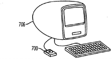
Figure 11 A-11D shows the application according to some embodiments of the present invention click wheel device.As stated, input media described here can be integrated in the electronic installation or can be autonomous device.Fig. 7 and Fig. 8 show some applying examples of the input media 700 that is integrated in the electronic installation.In Figure 11 A, can input media 700 be combined in the media player 702.In Figure 11 B, can input media 700 be combined in the kneetop computer 704.On the other hand, Figure 11 C and Figure 11 D show the applying examples of input media 700 as independent unit.In Figure 11 C, input media 700 is a peripherals, and it is connected to computed table 706.In Figure 11 D, input media 700 can be the telepilot that is wirelessly connected to docking station 708, and wherein media player 710 is docked at wherein.But, should be noted that telepilot also can be set to interact with direct and media player (or other electronic installations), eliminates the demand to docking station thus.The U.S. Patent Application Serial Number 10/423,490 of can be called " MEDIA PLAYER SYSTEM " in name, submitting on April 25th, 2003 finds the example of the docking station that is used for media player, by reference its full content is contained in this instructions.Should be noted that these specific embodiments are not restrictive, and can use a lot of other devices and structure.
With reference to figure 11A, will more describe media player 702 in detail again.Term " media player " general reference can be used for handling the calculation element of medium (for example, audio frequency, video or other images), for example music player, game machine, video player, video recorder and video camera etc.In some cases; Media player has simple function (for example, being exclusively used in the media player of playing back music), and in other cases; Media player has multiple function (for example, the media player of playing back music, display video and storage photograph etc.).Under any situation, where these devices generally can all can be listened in music, play games or displaying video, recording of video or shooting photograph to allow the user for portable.
In one embodiment, media player can be that size is suitable for being placed on the hand-held device in user's pocket.Through forming the pocket size; The user need not directly to grip this device; Therefore almost the user when any position all this device of portability (for example, bulky, the restriction of heavy device usually that the user is not gripped is as under the situation of kneetop computer or notebook computer.) for example, under the situation of music player, the user can use the said apparatus body-building in the gymnasium simultaneously.Under the situation of video camera, the user can use said apparatus to climb the mountain simultaneously.Under the situation of game machine, the user can use said apparatus in vehicle, to travel simultaneously.In addition, can be through user's manual manipulation said apparatus.Need not such as the such reference field of desktop.In the illustrated embodiment, media player 702 can be the hand-held MP3 music player of pocket size, and it allows the music (for example, in some cases up to the song of 4,000 first CD quality) of a large amount of collection of user storage.For example; The MP3 music player can be corresponding to the Apple Computer of California Cupertino,
 board MP3 player that Inc. makes.Although be mainly used in storage and playing back music, the MP3 music player shown in here also can have such as extra power abilities such as storage calendar and phone list, storage and game replaying and storage photographs.In fact, in some cases, it can be used as the high portability memory storage.
Shown in Figure 11 A, media player 702 comprises housing 722, and housing 722 is enclosed in inside with various electric assemblies (comprising IC chip and other circuit) and thinks that media player 702 provides calculating operation.In addition, housing 722 also can define the shape or the pattern of media player 702.That is, the profile of housing 722 can embody the solid appearance of media player 702.Be included in IC chip and other circuit in the housing 722 can comprise microprocessor (for example CPU), memory (for example, ROM, RAM), power supply (for example battery), circuit board, hard disk drive, other memories (for example flash memory) with and/or various I/O (I/O) support circuit.Electronic package also can comprise the assembly that is used to input or output music or sound, amplifier and the digital signal processor (DSP) such as microphone.Electronic package also can comprise the assembly that is used to catch image such as image sensor (for example, charge-coupled device (CCD) or complementary metal oxide semiconductor (CMOS) (CMOS)) or optical device (for example, lens, optical splitter, light filter).
In the illustrated embodiment, media player 702 for example can comprise the hard disk drive that gives media player super large memory capacity.For example, the 20GB hard disk drive can be stored up to 4000 first songs, promptly about 266 hours music.Compare, on average can store music up to 2GB (promptly about two hours) based on the media player of flash memory.Hard drive capacity can have a lot of changes (for example, 10,20GB etc.).Except hard disk drive, the media player 702 shown in here also can comprise accumulator, for example the lithium polymer secondary accumulator.The accumulator of these types can provide about 10 hours continuous playing duration for media player.
Media player 702 also can have display screen 724 and interlock circuit.Can use display screen 724 with to user's display graphical user interfaces and other information (for example, text, object, figure).For example, display screen 724 can be LCD (LCD).In a specific embodiment, display screen can be taken advantage of 128 pixel high resolution displaies corresponding to 160, and by day backlight and low light provides observability clearly according under the condition by white light LEDs.As shown in the figure, the user of media player 702 can see display screen 724 through the opening in the housing 722 725 and through the transparent wall 726 that can be arranged in opening 725 the place aheads.Although be transparent, because it helps to define the shape and the pattern of media player 702, so can transparent wall 726 be regarded as the part of housing 722.
Media player 702 also can comprise the touch pad 700 such as above-mentioned any type.Touch pad 700 can be roughly constitutes by be used to receive the tangible outside surface 731 that finger operates on touch pad 730.Although not shown in Figure 11 A, below tangible outside surface 731, sensor construction is arranged.Sensor construction can comprise a plurality of sensors, these sensors be provided in finger place above that, knock or through the time driven.Under the simplest situation,, finger can produce electric signal when being placed on the sensor at every turn.Number of signals in the given time limit can show position, direction, speed and the acceleration of finger on touch pad, that is, signal is many more, and it is many more that the user moves its finger.In most of the cases, can come pilot signal through electrical interface, electrical interface can be position, direction, speed and acceleration information with quantity, combination and the frequency inverted of signal.Media player 702 can utilize these information on display screen 724, to carry out the control function of hoping then.For example, through around touch pad 700 pivoting fingers, the user is the scrolling list of songs easily.
Except above setting, touch pad also can comprise one or more how removable key zone A-D and center button E.Key zone is set to be selected or gives an order the operation of media player 702 to be associated with so that one or more how special-purpose control function to be provided.For example, under the situation of MP3 player, keypress function can be associated with to be opened menu, played songs, F.F. song, searching menu and selects etc.Under many circumstances, stir work through mechanical. points and realize keypress function.
The shape of touch pad 700 also can have a lot of changes.Although the circle of being depicted as, touch pad can also be square, rectangle, and triangle etc.Particularly, touch pad is a ring-type, promptly is configured as similar ring-type or forms ring-type.Thus, the interior outer perimeter of touch pad has been decided the work border of touch pad.
Media player 702 also can comprise maintained switch 734.Maintained switch 734 can be set to drive or not driving touch panel and/or the button related with it.Do like this and be generally used for for example preventing when media player is placed in user's pocket that touch pad and/or button from causing the order of not expecting.When placing not driving condition, media player can not send (promptly ignoring) signal from button and/or touch pad.When placing driving condition, can be sent out and receive and handle by media player from the signal of button and/or touch pad.
In addition, media player 702 also can comprise one or more plurality of earphone jack 736 and one or more multidata port 738.Earphone jack 736 can receive the headset connector that is associated with earphone (being provided for listening to the sound by media player 702 outputs).On the other hand, FPDP 738 can receive data connector/cable-assembly, this assembly be set for to/from send and receive data such as the main frame of multi-purpose computer (for example, computed table, portable computer).For example, can use FPDP 738 to/upload or download audio frequency, video and other images from media player 702.For example, can use FPDP that song and playlist, audio books, e-book and photograph etc. are downloaded in the storing mechanism of media player.
FPDP 738 can have a lot of changes.For example, FPDP can be PS/2 port, serial port, parallel port, USB port, with and/or Firewire port etc.In some cases, FPDP 738 can be that radio frequency (RF) connects or optical infrared (IR) connects, to eliminate the demand to cable.Although not shown in Figure 11 A, media player 702 also can comprise power port, and it receives electric connector/cable-assembly, and this assembly is set for electric power is delivered to media player 702.In some cases, FPDP 738 can play a part FPDP and power port both.In the illustrated embodiment, FPDP 738 is the Firewire ports that have data and two kinds of performances of power supply concurrently.
Although only show a data port, be to be understood that this is also unrestricted, can a plurality of FPDPs be combined in the media player.Similarly, FPDP can have the several data function, that is, the function of several data port is integrated in the single FPDP.In addition, should be appreciated that can there be a lot of changes maintained switch, earphone jack and the FPDP position on housing.That is, it is not limited to the position shown in Figure 11 A.Almost can it be arranged in optional position on the housing (for example, front, the back side, side, top, bottom).For example, can FPDP be arranged on the top surface of housing but not on the illustrated basal surface.
Figure 12 A and Figure 12 B show according to some embodiments of the present invention installation to input media in media player.For example, input media 750 can be corresponding to aforementioned any type, and media player 752 can be corresponding to the type shown in Figure 11 A.As shown in the figure, input media 750 can comprise housing 754 and touch pad component 756.Media player 752 can comprise shell, and promptly housing 758.The face wall 760 of shell 758 can comprise opening 762, and when input media 750 was introduced media player 752, opening 762 allowed operation touch pad component 756.The inboard of antetheca 760 can comprise groove, and promptly conduit 764, is used for the input media 750 in the shell 758 of receiving media player 752.The edge of groove 764 with the housing 754 that receives input media 750 can be set, thus input media 750 position of its hope to the shell 758 slidably.Groove has the shape that roughly is consistent with the shape of housing 754.At assembly process, the circuit board 766 of touch pad component 756 is aimed at opening 762, and decorated disk 768 and button cover 770 are installed on the end face of circuit board 766.As shown in the figure, decorated disk 768 has the shape that roughly is consistent with opening 762.Can be through such as screw, grab, bonding agent, fit mechanism and clamp-on rib etc. input media is remained in the groove.
Figure 13 shows the simplified block diagram that has combined the telepilot of input media according to some embodiments of the present invention.For example, input media 782 can be corresponding to the above-mentioned input media of any type.In this specific embodiment, input media 782 can be corresponding to the input media shown in Fig. 6 A-6C and Fig. 7 A-7C, so input media comprises touch pad 784 and a plurality of switch 786.Touch pad 784 and switch 786 can may be operably coupled to wireless launcher 788.Wireless launcher 788 can be set to connect transmission information, make electronic installation to connect reception information through radio communication with receiving ability through radio communication.Wireless launcher 788 can have a lot of changes.For example, its can based on such as FM, RF, bluetooth, 802.11UWB (ultra broadband), IR, with and/or magnetic connect wireless technologys such as (inductions).In the illustrated embodiment, wireless launcher 788 is based on IR.IR can make a general reference the wireless technology through infrared radiation transmission data.Therefore, wireless launcher 788 can roughly comprise IR controller 790.IR controller 790 can obtain the information by touch pad 784 and switch 786 reports, and can for example utilize light emitting diode 792 that above-mentioned information translation is infrared ray.
To understand above-mentioned clearly the description and embodiments of the invention be described with reference to different function units and processor.But, should be understood that, do not break away from the present invention, can be between different functional units or processor distribution function suitably.For example, the function of being accomplished by separate processor or controller shown in can be accomplished by single-processor or controller.Therefore, should be regarded as description to the appropriate device that is used to provide said function to the description of specific functional units, but not the expression stricti jurise in logic or structure on the entity or setting.
The present invention can any suitable form realize, comprises hardware, software, firmware or its combination in any.The present invention also can be partly to realize at one or the computer software that more moves on multidata processor and/or the digital signal processor.The element of embodiments of the invention and assembly can any suitable form realized on the entity, on the function and in logic.In fact, can be in single unit, a plurality of unit or realize above-mentioned functions as the part of other functional units.Therefore, the present invention can realize in single unit, perhaps between different units and processor, carries out aspect the entity and the distribution of function aspects.
It should be appreciated by those skilled in the art that various feasible change and the combination that to use announcement embodiment, still adopt identical basic mechanism and method simultaneously.Carried out foregoing description for the purpose of description with reference to specific embodiment.But above-mentioned illustrative is described and is not intended to and carries out exhaustive for example, the description of the concrete form that perhaps is not limited to be disclosed.Being conceived to above-mentioned instruction can much change and revise.Selection of the foregoing description and description are for the principle of the present invention and practical application thereof is described, and make those skilled in the art to come optimal with the present invention and various embodiment with the various changes that are suitable for required concrete application.
Claims (9)
1. device comprises:
Touch pad, button, plate, first switch and second switch,
Said touch pad is configured to around said button,
When being configured in being constrained on framework, said touch pad carries out universal movement with respect to said framework,
In said first switch and the said second switch at least one is in said button aligned beneath, and said first switch and said second switch are configured to for said button with for said touch pad the mechanical spring action is provided,
Said plate is configured to extending below the said touch pad and between said first switch and said second switch,
Said plate is configured to the power that applies to said touch pad from said touch pad to said second switch and not to the said first switch transmission, wherein,
The power that applies to said touch pad makes said second switch activation and does not make said first switch activator, and
The power that applies to said button makes said first switch activator and said second switch is activated.
2. device as claimed in claim 1 wherein, activates the required power of said second switch greater than activating the required power of said first switch.
3. device as claimed in claim 1, wherein, said first switch is configured to carry out universal movement with respect to said touch pad.
4. device as claimed in claim 1, wherein, at least one in said first switch and the said second switch comprises dome switch.
5. device comprises:
First input component, when being configured to provide positional information and being configured in being constrained on framework with respect to said frame movement,
Second input component is configured to provide movable information,
Plate,
First switch and
Second switch,
In said first switch and the said second switch at least one aimed at said second input component,
Said plate is configured to extending below said first input component and between said first switch and said second switch,
Said plate is configured to the power that applies to said first input component from said first input component to said second switch and not to the said first switch transmission, wherein,
The power that applies to said first input component makes said second switch activation and does not make said first switch activator, and
The power that applies to said second input component makes said first switch activator and said second switch is activated.
6. device as claimed in claim 5 wherein, activates the required power of said second switch greater than activating the required power of said first switch.
7. device as claimed in claim 5, wherein, said first switch is configured to carry out universal movement with respect to said first input component.
8. device as claimed in claim 5, wherein, at least one in said first switch and the said second switch comprises dome switch.
9. device comprises:
First input component, when being configured to provide positional information and being configured in being constrained on framework with respect to said frame movement,
Second input component is configured to provide movable information,
Plate,
First switch and
Second switch,
In said first switch and the said second switch at least one aimed at said second input component,
Said plate is configured to extending below said first input component and between said first switch and said second switch,
Said plate is configured to the power that applies to said first input component from said first input component to said second switch and not to the said first switch transmission, wherein,
Said second switch can: with respect to the power that applies to said first input component activation that said first switch carries out is activated independently and side by side, and
Said first switch can: the power with respect to applying to said second input component is activated as far as the activation that said second switch carries out independently and side by side, thereby makes
Said first input component and said second input component can be used to generate single order simultaneously.
Applications Claiming Priority (2)
| Application Number | Priority Date | Filing Date | Title |
|---|---|---|---|
| US11/812,384 | 2007-06-18 | ||
| US11/812,384 US20080088597A1 (en) | 2006-10-11 | 2007-06-18 | Sensor configurations in a user input device |
Related Parent Applications (1)
| Application Number | Title | Priority Date | Filing Date |
|---|---|---|---|
| CN200780038246.6A Division CN101641663B (en) | 2007-06-18 | 2008-02-28 | Sensor structure in user input device |
Publications (1)
| Publication Number | Publication Date |
|---|---|
| CN102759992A true CN102759992A (en) | 2012-10-31 |
Family
ID=40590085
Family Applications (2)
| Application Number | Title | Priority Date | Filing Date |
|---|---|---|---|
| CN201110436581XA Pending CN102759992A (en) | 2007-06-18 | 2008-02-28 | Sensor configurations in a user input device |
| CN200780038246.6A Expired - Fee Related CN101641663B (en) | 2007-06-18 | 2008-02-28 | Sensor structure in user input device |
Family Applications After (1)
| Application Number | Title | Priority Date | Filing Date |
|---|---|---|---|
| CN200780038246.6A Expired - Fee Related CN101641663B (en) | 2007-06-18 | 2008-02-28 | Sensor structure in user input device |
Country Status (3)
| Country | Link |
|---|---|
| EP (1) | EP2168031A2 (en) |
| CN (2) | CN102759992A (en) |
| AU (1) | AU2007313960B2 (en) |
Cited By (4)
| Publication number | Priority date | Publication date | Assignee | Title |
|---|---|---|---|---|
| CN108139812A (en) * | 2015-10-19 | 2018-06-08 | 微软技术许可有限责任公司 | Haptics for Handheld Input Devices |
| CN110737122A (en) * | 2018-07-19 | 2020-01-31 | 敦泰电子有限公司 | liquid crystal display module, control method and electronic equipment |
| CN111829429A (en) * | 2019-04-23 | 2020-10-27 | 丰田自动车株式会社 | switchgear |
| CN112445148A (en) * | 2020-12-08 | 2021-03-05 | 厦门立林科技有限公司 | User-defined key control method with display screen and device thereof |
Families Citing this family (28)
| Publication number | Priority date | Publication date | Assignee | Title |
|---|---|---|---|---|
| EP2450776A1 (en) * | 2010-10-20 | 2012-05-09 | Nxp B.V. | User-interface for controlling a data processing system using a joystick |
| CN103324326B (en) * | 2012-03-22 | 2016-10-05 | 中国移动通信集团公司 | A kind of touch-screen and device |
| KR101397084B1 (en) * | 2012-07-02 | 2014-05-20 | 엘지전자 주식회사 | Mobile terminal |
| CN109634447B (en) | 2013-08-09 | 2022-04-19 | 苹果公司 | Tactile switch for electronic devices |
| US10048802B2 (en) | 2014-02-12 | 2018-08-14 | Apple Inc. | Rejection of false turns of rotary inputs for electronic devices |
| WO2016008527A1 (en) * | 2014-07-16 | 2016-01-21 | Vega Grieshaber Kg | Field device with an input unit |
| JP6342453B2 (en) * | 2016-07-07 | 2018-06-13 | 本田技研工業株式会社 | Operation input device |
| US10061399B2 (en) | 2016-07-15 | 2018-08-28 | Apple Inc. | Capacitive gap sensor ring for an input device |
| US10019097B2 (en) | 2016-07-25 | 2018-07-10 | Apple Inc. | Force-detecting input structure |
| KR20180049544A (en) * | 2016-11-03 | 2018-05-11 | 현대자동차주식회사 | Touch controll device |
| CN110114743B (en) * | 2016-12-30 | 2022-11-11 | 微软技术许可有限责任公司 | pointing device |
| CN106952591A (en) * | 2017-04-06 | 2017-07-14 | 许昌学院 | Strap-type night running warning device |
| CN107247921B (en) * | 2017-05-15 | 2023-11-21 | 华勤技术股份有限公司 | Induction method and device |
| US10962935B1 (en) | 2017-07-18 | 2021-03-30 | Apple Inc. | Tri-axis force sensor |
| US20190317454A1 (en) | 2018-04-13 | 2019-10-17 | Apple Inc. | Coherent Mixing Interference Based Sensors for Characterizing Movement of a Watch Crown |
| US11360440B2 (en) * | 2018-06-25 | 2022-06-14 | Apple Inc. | Crown for an electronic watch |
| US11561515B2 (en) | 2018-08-02 | 2023-01-24 | Apple Inc. | Crown for an electronic watch |
| US12259690B2 (en) * | 2018-08-24 | 2025-03-25 | Apple Inc. | Watch crown having a conductive surface |
| CN209560398U (en) | 2018-08-24 | 2019-10-29 | 苹果公司 | digital watch |
| CN209625187U (en) | 2018-08-30 | 2019-11-12 | 苹果公司 | Electronic Watches and Electronic Devices |
| US11194299B1 (en) | 2019-02-12 | 2021-12-07 | Apple Inc. | Variable frictional feedback device for a digital crown of an electronic watch |
| WO2021081738A1 (en) * | 2019-10-29 | 2021-05-06 | 深圳市汇顶科技股份有限公司 | Slide signal recognition method, mcu, touch-control device, and storage medium |
| US11550268B2 (en) | 2020-06-02 | 2023-01-10 | Apple Inc. | Switch module for electronic crown assembly |
| CN114327156B (en) * | 2020-09-29 | 2024-08-20 | 宸鸿科技(厦门)有限公司 | Touch element and device comprising same |
| US12092996B2 (en) | 2021-07-16 | 2024-09-17 | Apple Inc. | Laser-based rotation sensor for a crown of an electronic watch |
| US11674825B2 (en) | 2021-09-21 | 2023-06-13 | Apple Inc. | Cylindrical retroreflector array for rotation tracking |
| JP7586127B2 (en) * | 2022-04-11 | 2024-11-19 | トヨタ自動車株式会社 | Parking management device, vehicle, and parking management method |
| US12189347B2 (en) | 2022-06-14 | 2025-01-07 | Apple Inc. | Rotation sensor for a crown of an electronic watch |
Citations (3)
| Publication number | Priority date | Publication date | Assignee | Title |
|---|---|---|---|---|
| US20040200699A1 (en) * | 2003-04-11 | 2004-10-14 | Tadanao Matsumoto | Depression responsive switch unit |
| CN1894942A (en) * | 2003-12-19 | 2007-01-10 | 诺基亚公司 | Rotator wheel |
| CN1926604A (en) * | 2003-08-18 | 2007-03-07 | 苹果电脑公司 | Removable touchpad for added functionality |
Family Cites Families (1)
| Publication number | Priority date | Publication date | Assignee | Title |
|---|---|---|---|---|
| US20060181517A1 (en) * | 2005-02-11 | 2006-08-17 | Apple Computer, Inc. | Display actuator |
-
2008
- 2008-02-28 CN CN201110436581XA patent/CN102759992A/en active Pending
- 2008-02-28 AU AU2007313960A patent/AU2007313960B2/en not_active Ceased
- 2008-02-28 EP EP07853842A patent/EP2168031A2/en not_active Withdrawn
- 2008-02-28 CN CN200780038246.6A patent/CN101641663B/en not_active Expired - Fee Related
Patent Citations (3)
| Publication number | Priority date | Publication date | Assignee | Title |
|---|---|---|---|---|
| US20040200699A1 (en) * | 2003-04-11 | 2004-10-14 | Tadanao Matsumoto | Depression responsive switch unit |
| CN1926604A (en) * | 2003-08-18 | 2007-03-07 | 苹果电脑公司 | Removable touchpad for added functionality |
| CN1894942A (en) * | 2003-12-19 | 2007-01-10 | 诺基亚公司 | Rotator wheel |
Cited By (6)
| Publication number | Priority date | Publication date | Assignee | Title |
|---|---|---|---|---|
| CN108139812A (en) * | 2015-10-19 | 2018-06-08 | 微软技术许可有限责任公司 | Haptics for Handheld Input Devices |
| CN108139812B (en) * | 2015-10-19 | 2021-02-09 | 微软技术许可有限责任公司 | Haptic sensations for handheld input devices |
| CN110737122A (en) * | 2018-07-19 | 2020-01-31 | 敦泰电子有限公司 | liquid crystal display module, control method and electronic equipment |
| CN110737122B (en) * | 2018-07-19 | 2022-10-25 | 敦泰电子有限公司 | Liquid crystal display module, control method and electronic equipment |
| CN111829429A (en) * | 2019-04-23 | 2020-10-27 | 丰田自动车株式会社 | switchgear |
| CN112445148A (en) * | 2020-12-08 | 2021-03-05 | 厦门立林科技有限公司 | User-defined key control method with display screen and device thereof |
Also Published As
| Publication number | Publication date |
|---|---|
| AU2007313960B2 (en) | 2010-09-30 |
| EP2168031A2 (en) | 2010-03-31 |
| AU2007313960A1 (en) | 2008-05-08 |
| CN101641663A (en) | 2010-02-03 |
| CN101641663B (en) | 2015-03-18 |
Similar Documents
| Publication | Publication Date | Title |
|---|---|---|
| CN201262741Y (en) | User input device with sensor structure | |
| CN102759992A (en) | Sensor configurations in a user input device | |
| TWI390430B (en) | Device for multiple inputs | |
| US20210116961A1 (en) | Actuating user interface for media player | |
| TWI387905B (en) | Sensor configurations in a user input device | |
| CN102200859B (en) | Movable touch pad with added functionality | |
| AU2008100566A4 (en) | Method and apparatus for implementing multiple push buttons in a user input device | |
| AU2008100382B4 (en) | A portable media device |
Legal Events
| Date | Code | Title | Description |
|---|---|---|---|
| C06 | Publication | ||
| PB01 | Publication | ||
| C10 | Entry into substantive examination | ||
| SE01 | Entry into force of request for substantive examination | ||
| C05 | Deemed withdrawal (patent law before 1993) | ||
| WD01 | Invention patent application deemed withdrawn after publication |
Application publication date: 20121031 |