CN102759878A - Unit mount-demount mechanism and image forming apparatus including the same - Google Patents
Unit mount-demount mechanism and image forming apparatus including the same Download PDFInfo
- Publication number
- CN102759878A CN102759878A CN2012101325868A CN201210132586A CN102759878A CN 102759878 A CN102759878 A CN 102759878A CN 2012101325868 A CN2012101325868 A CN 2012101325868A CN 201210132586 A CN201210132586 A CN 201210132586A CN 102759878 A CN102759878 A CN 102759878A
- Authority
- CN
- China
- Prior art keywords
- unit
- image forming
- roller
- main body
- rail
- Prior art date
- Legal status (The legal status is an assumption and is not a legal conclusion. Google has not performed a legal analysis and makes no representation as to the accuracy of the status listed.)
- Granted
Links
- 238000003780 insertion Methods 0.000 claims abstract description 36
- 230000037431 insertion Effects 0.000 claims abstract description 36
- 238000011144 upstream manufacturing Methods 0.000 claims abstract description 15
- 238000012545 processing Methods 0.000 claims description 3
- 238000012546 transfer Methods 0.000 description 12
- 239000002184 metal Substances 0.000 description 8
- 238000004140 cleaning Methods 0.000 description 4
- 238000010438 heat treatment Methods 0.000 description 3
- 238000012423 maintenance Methods 0.000 description 3
- 238000013459 approach Methods 0.000 description 2
- 230000015572 biosynthetic process Effects 0.000 description 2
- 238000000605 extraction Methods 0.000 description 2
- 238000000034 method Methods 0.000 description 2
- 108091008695 photoreceptors Proteins 0.000 description 2
- 239000002131 composite material Substances 0.000 description 1
- 230000007423 decrease Effects 0.000 description 1
- 230000007547 defect Effects 0.000 description 1
- 238000007599 discharging Methods 0.000 description 1
- 238000009434 installation Methods 0.000 description 1
- 238000012986 modification Methods 0.000 description 1
- 230000004048 modification Effects 0.000 description 1
- 230000002265 prevention Effects 0.000 description 1
- 238000011084 recovery Methods 0.000 description 1
- 239000011347 resin Substances 0.000 description 1
- 229920005989 resin Polymers 0.000 description 1
- 230000003068 static effect Effects 0.000 description 1
- 239000002699 waste material Substances 0.000 description 1
Images


Classifications
-
- G—PHYSICS
- G03—PHOTOGRAPHY; CINEMATOGRAPHY; ANALOGOUS TECHNIQUES USING WAVES OTHER THAN OPTICAL WAVES; ELECTROGRAPHY; HOLOGRAPHY
- G03G—ELECTROGRAPHY; ELECTROPHOTOGRAPHY; MAGNETOGRAPHY
- G03G21/00—Arrangements not provided for by groups G03G13/00 - G03G19/00, e.g. cleaning, elimination of residual charge
- G03G21/16—Mechanical means for facilitating the maintenance of the apparatus, e.g. modular arrangements
- G03G21/18—Mechanical means for facilitating the maintenance of the apparatus, e.g. modular arrangements using a processing cartridge, whereby the process cartridge comprises at least two image processing means in a single unit
- G03G21/1839—Means for handling the process cartridge in the apparatus body
- G03G21/1842—Means for handling the process cartridge in the apparatus body for guiding and mounting the process cartridge, positioning, alignment, locks
Landscapes
- Engineering & Computer Science (AREA)
- Computer Vision & Pattern Recognition (AREA)
- Physics & Mathematics (AREA)
- General Physics & Mathematics (AREA)
- Electrophotography Configuration And Component (AREA)
Abstract
Description
技术领域 technical field
本发明涉及相对于图像形成装置主体可装卸的单元装卸机构以及包括该单元装卸机构的图像形成装置。The present invention relates to a unit attaching and detaching mechanism that can be attached to and detached from an image forming apparatus main body, and an image forming apparatus including the unit attaching and detaching mechanism.
背景技术 Background technique
以往,在使用电子照片处理的图像形成装置中,通过螺钉将定影单元、感光鼓单元、显影单元、中间转印单元等固定到图像形成装置内部的预定的位置上。另一方面,在卡纸(塞纸)处理时需要将这些单元从图像形成装置主体取下。另外,当所述单元的耐用年数比装置主体的寿命短时,需要定期地进行更换。Conventionally, in an image forming apparatus using electrophotographic processing, a fixing unit, a photosensitive drum unit, a developing unit, an intermediate transfer unit, and the like are fixed to predetermined positions inside the image forming apparatus by screws. On the other hand, these units need to be removed from the main body of the image forming apparatus when handling paper jams (paper jams). In addition, when the service life of the unit is shorter than the life of the device main body, it needs to be replaced periodically.
在上述的以往的构成中,每当进行单元的更换时或卡纸(塞纸)处理时都必须联系服务人员,因此效率低下。另一方面,使用螺丝刀等工具进行单元的装卸作业对于一般的用户构成很大的负担。因此,由用户简单地进行单元的更换作业的方法被提出,并且沿着设置在图像形成装置主体侧的引导形状将单元插入或拉出的构成被广泛地采用。In the conventional configuration described above, it is inefficient to call a service person every time a unit is replaced or a paper jam (paper jam) is dealt with. On the other hand, attaching and detaching the unit using a tool such as a screwdriver places a heavy burden on the general user. Therefore, a method for the user to easily replace the unit has been proposed, and a configuration in which the unit is inserted or pulled out along a guide shape provided on the main body of the image forming apparatus is widely used.
例如,已知下述的显影装置的装卸机构,该显影装置的装卸机构通过在位于装置主体侧的导轨面侧的两个辊之间设置引导部件,将显影装置在安装和取下时的倾斜度限制在预定范围内,使得感光体不会被显影辊等部件损伤。For example, there is known an attachment and detachment mechanism for a developing device that adjusts the inclination of the developing device during installation and removal by providing a guide member between two rollers located on the side of the guide rail surface on the device main body side. The degree is limited within a predetermined range so that the photoreceptor will not be damaged by components such as the developing roller.
另外,已知一种图像形成装置,该图像形成装置包括:导引具有感光体的单元的引导轴的向下倾斜的一对第一倾斜引导部;以及配置在一对第一倾斜引导部之间并且以与第一倾斜引导部相同的方向向下倾斜从而导引单元的底面的第二倾斜引导部,在单元到达插入停止位置时,使单元的后部向下转动从而能够使其容纳并固定在容纳部中。In addition, there is known an image forming apparatus including: a pair of downwardly inclined first inclined guides for guiding a guide shaft of a unit having a photoreceptor; and a pair of first inclined guides disposed between the pair of first inclined guides. and the second inclined guide that guides the bottom surface of the unit by inclining downward in the same direction as the first inclined guide, when the unit reaches the insertion stop position, turns the rear of the unit downward so that it can be accommodated and fixed in the receptacle.
在如上所述的将单元插入图像形成装置主体内或者将单元从图像形成装置主体内拉出的构成中,由于装置的紧凑化的要求或布局上的限制等,有时在单元的插入和拉出路径中存在其他的单元或部件。In the configuration of inserting the unit into the main body of the image forming apparatus or pulling the unit out of the main body of the image forming apparatus as described above, due to the requirement for compactness of the apparatus or restrictions on the layout, etc. There are other units or components in the path.
此时,需要一边回避其他单元或部件一边进行目标单元的插入和拉出操作,因此插入和拉出路径的轨道不再是直线而变得复杂。另外,单元的插入和拉出操作也变得烦杂。另外,存在单元在图像形成装置主体内的定位精度下降、容易发生齿轮的啮合不良或图像不良这样的问题。At this time, it is necessary to perform insertion and extraction operations of the target unit while avoiding other units or components, so the trajectory of the insertion and extraction path is no longer a straight line and becomes complicated. In addition, the operation of inserting and pulling out the unit becomes cumbersome. In addition, there is a problem that the positioning accuracy of the unit in the main body of the image forming apparatus decreases, and poor meshing of gears and image defects tend to occur.
发明内容 Contents of the invention
本发明是鉴于上述问题而做出的,本发明的目的是提供能够相对于图像形成装置主体容易地装卸单元并且能够将单元高精度地定位在图像形成装置主体上的装卸机构、以及包括该装卸机构的图像形成装置。The present invention has been made in view of the above problems, and an object of the present invention is to provide an attaching and detaching mechanism capable of easily attaching and detaching a unit to the image forming apparatus main body and positioning the unit on the image forming apparatus main body with high precision, and an apparatus including the attaching and detaching mechanism. Institutional image forming device.
为了实现上述目的,本发明的一个方面涉及的单元的装卸机构具有相对于装置主体可装卸的单元、以及被安装在装置主体侧的一对滑轨,所述一对滑轨可滑动地支承所述单元的与装卸方向平行的两侧面,在所述单元的与装卸方向平行的两侧面上,由相对于所述单元插入方向配置在下游侧的第一辊以及相对于所述单元插入方向配置在上游侧的第二辊构成的单元侧辊在所述单元的各侧面上各设有一对,所述滑轨中形成有由下侧导轨和上侧导轨构成的导轨槽,所述单元侧辊与导轨槽卡合,在所述上侧导轨或下侧导轨的一部分上形成有使所述单元侧辊从所述导轨槽中脱轨的缺口部,通过使所述第一辊或所述第二辊中的任一者从所述导轨槽中脱轨,将所述单元定位在所述装置主体内的预定位置上。In order to achieve the above objects, a unit attachment and detachment mechanism according to an aspect of the present invention has a unit that can be attached to and detached from the device main body, and a pair of slide rails mounted on the device main body side, and the pair of slide rails slidably supports the unit. On both sides of the unit parallel to the loading and unloading direction, on the two side surfaces of the unit parallel to the loading and unloading direction, there are first rollers arranged on the downstream side with respect to the insertion direction of the unit and a first roller arranged on the downstream side with respect to the insertion direction of the unit. A pair of unit side rollers consisting of second rollers on the upstream side are respectively provided with a pair on each side of the unit, and a guide rail groove composed of a lower side guide rail and an upper side guide rail is formed in the slide rail, and the unit side rollers Engaged with the guide rail groove, a notch is formed on a part of the upper side guide rail or the lower side guide rail to derail the unit side roller from the guide rail groove. By making the first roller or the second roller Any one of the rollers is derailed from the rail groove, positioning the unit at a predetermined position within the device body.
另外,为了实现上述目的,本发明的一个方面涉及的图像形成装置包括上述的单元的装卸机构。In addition, in order to achieve the above object, an image forming apparatus according to one aspect of the present invention includes the above-mentioned unit attaching and detaching mechanism.
本发明的其他的目的、由本发明得到的具体的优点通过下述的实施方式的说明将变得更加清楚。Other objects of the present invention and specific advantages obtained by the present invention will become clearer through the description of the following embodiments.
附图说明 Description of drawings
图1是示出本发明的一个实施方式涉及的图像形成装置的内部构成的概略剖面图;1 is a schematic cross-sectional view showing an internal configuration of an image forming apparatus according to an embodiment of the present invention;
图2是图1中的图像形成装置100的图像形成部9的剖面立体图;FIG. 2 is a cross-sectional perspective view of the
图3是从图1的内侧观察图像形成单元30的俯视立体图;FIG. 3 is a top perspective view of the
图4是从图1的内侧观察图像形成单元30的仰视立体图;FIG. 4 is a bottom perspective view of the
图5是示出从图像形成单元30取下调色剂容器20之后的状态的立体图;5 is a perspective view showing a state after the
图6是示出从图5的状态进一步取下显影装置16的过程的状态的立体图;FIG. 6 is a perspective view showing a state in which the developing
图7是调色剂容器20和显影装置16被取下后的图像形成单元30的立体图;7 is a perspective view of the
图8是可滑动地支承图像形成单元30的滑轨35的立体图,并且是示出第二导轨部35b处于被容纳在第一导轨部35a中的位置的状态的图;8 is a perspective view of the
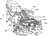
图9是可滑动地支承图像形成单元30的滑轨35的立体图,并且是示出第二导轨部35b处于从第一导轨部35a被拉出的位置的状态的图;9 is a perspective view of the
图10是示出图像形成单元30相对于运送单元50被最大程度拉出的状态的立体图;FIG. 10 is a perspective view showing a state where the
图11是示出图10中的滑轨35和图像形成单元30的金属板框31a、31b之间的位置关系的立体图;FIG. 11 is a perspective view showing the positional relationship between the
图12是示出从图10的状态将图像形成单元30相对于运送单元50压入预定量后的状态的立体图;FIG. 12 is a perspective view showing a state in which the
图13是示出图12中的滑轨35和图像形成单元30的金属板框31a、31b之间的位置关系的立体图;FIG. 13 is a perspective view showing the positional relationship between the
图14是示出从图12的状态将图像形成单元30相对于运送单元50压入预定量后的状态的立体图;FIG. 14 is a perspective view showing a state in which the
图15是示出从图14的状态将图像形成单元30相对于运送单元50压入预定量后的状态的立体图;FIG. 15 is a perspective view showing a state in which the
图16是示出从图14的状态将图像形成单元30相对于运送单元50压入预定量后的状态的侧视图;FIG. 16 is a side view showing a state in which the
图17是示出图15、图16中的滑轨35和图像形成单元30的金属板框31a、31b之间的位置关系的立体图;17 is a perspective view showing the positional relationship between the
图18是示出第二辊33b经由第二导轨部35b的缺口部43脱轨后的状态的立体图;FIG. 18 is a perspective view illustrating a state where the
图19是第二辊33b脱轨后的状态下、图像形成单元30和运送单元50的侧视剖面图;19 is a side sectional view of the
图20是图19中的卡合突起55和锁定部件57周边的局部放大图;FIG. 20 is a partially enlarged view of the periphery of the
图21是示出将图像形成单元30插入运送单元50直至预定位置后的状态的立体图;FIG. 21 is a perspective view showing a state after the
图22是示出将图像形成单元30插入运送单元50直至预定位置的状态的侧视图;FIG. 22 is a side view showing a state where the
图23是示出将图像形成单元30插入运送单元50直至预定位置的状态的侧视剖面图。FIG. 23 is a side sectional view showing a state where the
具体实施方式 Detailed ways
以下,参照附图对本发明的实施方式进行说明。图1是本发明的一个实施方式涉及的图像形成装置的概略剖面图,图2是图像形成装置的图像形成部9的剖面立体图。如图1所示,图像形成装置100(在此是单色打印机)在主体下部包括容纳堆积的纸张的供纸盒2。该供纸盒2的上方形成有纸张运送路径,该纸张运送路径从主体前(这里是左方)向主体后大致水平地延伸,并进一步向上方延伸直至形成于主体上表面的排出托盘19,沿着该纸张运送路径从上游侧依次配置有拾取辊5、供纸辊对6、中间运送辊7、阻挡辊对8、图像形成部9、定影部10、以及排出辊对11。此外,图像形成装置100内还配置有控制上述的各辊、图像形成部9、定影部10等的动作的控制部(未图示)。Hereinafter, embodiments of the present invention will be described with reference to the drawings. 1 is a schematic sectional view of an image forming apparatus according to an embodiment of the present invention, and FIG. 2 is a sectional perspective view of an
供纸盒2中包括被设置在纸张运送方向后端部的旋转支点12a相对于供纸盒2可自由旋转地支承的纸张堆积板12,并且堆积在纸张堆积板12上的纸张被拾取辊5按压。另外,供纸盒2的前侧配置有由喂料辊6a和与喂料辊6a压接的阻尼辊6b的供纸辊对6,当通过拾取辊5同时供应多张纸张时,纸张被所述喂料辊6a和阻尼辊6b分开,并且仅最上的一张纸张被运送。The
然后,被喂料辊6a和阻尼辊6b分开的纸张,运送方向被中间运送辊7变为朝向装置后方而被运向阻挡辊对8,并且被阻挡辊对8调整时机而被供应给图像形成部9。Then, the paper separated by the
图像形成部9通过电子照片处理在纸张上形成预定的调色剂图像,并包括:感光鼓14,感光鼓14是在图1中可逆时针方向旋转地被轴支承的图像载体;配置在该感光鼓14的周围的带电装置15;显影装置16;清洁装置17;隔着纸张运送路径4而与感光鼓14相对地配置的转印辊18;以及配置在感光鼓14的上方的曝光单元(LSU)4,在显影装置16的上方配置有向显影装置16补充调色剂的调色剂容器20。The
感光鼓14与带电装置15和清洁装置17一起构成感光鼓单元21。另外,感光鼓单元21与显影装置16和调色剂容器20一起构成相对于图像形成装置100主体可整体地插入和拉出的图像形成单元30。构成图像形成单元30的感光鼓单元21、显影装置16、以及调色剂容器20可相互分离。中间运送辊7、阻挡辊对8、转印辊18被附设在运送单元50中,运送单元50被配置在图像形成单元30的下方。此外,在图2中仅图示了运送单元50的一部分。The
在带电装置15中,包括与未图示的电源连接的导电性橡胶辊,并且该导电性橡胶辊被配置为与感光鼓14抵接。因此,当感光鼓14旋转时,导电性橡胶辊与感光鼓14的表面接触从而进行从动旋转,此时,通过对导电性橡胶辊施加预定的电压,感光鼓14的表面被均等地带电。The charging
接下来,通过来自曝光单元4的激光束在感光鼓14上形成基于所输入的图像数据的静电潜像,并通过显影装置16使调色剂附着于静电潜像从而在感光鼓14的表面上形成调色剂图像。另外,通过转印辊18将感光鼓14的表面的调色剂图像转印到被供应到形成于感光鼓14和转印辊18之间的压印部中的转印位置的纸张上。Next, an electrostatic latent image based on the input image data is formed on the
转印有调色剂图像的纸张与感光鼓14分离而被运向定影部10。该定影部10被配置在图像形成部9的纸张运送方向的下游侧,在图像形成部9中转印了调色剂图像的纸张被定影部10所包括的加热辊以及与该加热辊压接的加压辊进行加热和加压,由此被转印的调色剂图像被定影在纸张上。The paper on which the toner image has been transferred is separated from the
然后,在图像形成部9和定影部10中实施图像形成后的纸张被排出辊对11排出到排出托盘19。另一方面,转印后残留在感光鼓14表面上的调色剂被清洁装置17去除,并且感光鼓14表面的残留电荷被除电装置(未图示)去除。然后,通过带电装置15使感光鼓14再次带电,下面以同样的方式进行图像形成。Then, the paper on which the image has been formed in the
图3和图4分别是从图1的里侧上方和里侧下方观察图像形成单元30的立体图。金属板框31a、31b被固定到构成图像形成单元30的感光鼓单元21的两侧面上,并且一对单元侧辊33被可自由旋转地安装在各金属板框31a、31b上。3 and 4 are perspective views of the
单元侧辊33由相对单元插入方向下游侧的第一辊33a和上游侧的第二辊33b构成,并且在构成滑轨35(参照图8)的第二导轨部35b的内侧形成的导轨槽41(参照图8)内一边旋转一边移动,滑轨35设置在图像形成装置100主体侧。由此,感光鼓单元21沿着第二导轨部35b可滑动地被支承。The
另外,在形成于第一导轨部35a中的滑动孔40(参照图8)内移动的两个导轨侧辊37a、37b可自由旋转地被安装到第二导轨部35b的外侧。在感光鼓单元21的内侧(图4的前侧),感光鼓14的旋转轴14a和螺旋轴承17a突出,用于向外部排出清洁装置17(参照图1)内的废调色剂的回收螺杆的旋转轴插入螺旋轴承17a中。此外,在图4中没有示出第二导轨部35b。In addition, two
图5是示出从图像形成单元30中取下调色剂容器20后的状态的立体图,图6是示出从图5的状态进一步取下显影装置16的过程的状态的立体图,图7是调色剂容器20和显影装置16被取下后的图像形成单元30的立体图。此外,图5~图7示出了从图1的前侧观察图像形成单元30的状态,图像形成单元30的朝向与图3和图4中是相反的。5 is a perspective view showing a state in which the
通过从图3和图4的状态相对单元插入方向提起调色剂容器20的上游侧端部,如图5所示,从图像形成单元30的第一容纳部30a中取下调色剂容器20。另外,如图6所示,通过相对单元插入方向把持并提起显影装置16的上游侧端部(图6的左侧端部),如图7所示,从图像形成单元30的第二容纳部30b取下显影装置16。在感光鼓单元21的前侧(图5的前侧),插入有感光鼓14的旋转轴14a的感光鼓轴承14b突出。By lifting the upstream side end of
图8和图9是可滑动地支承图像形成单元30的滑轨35的立体图。滑轨35由第一导轨部35a和第二导轨部35b构成,第一导轨部35a被固定在图像形成装置100主体的侧面框25a(参照图2)。第一导轨部35a中形成有滑动孔40,并且第二导轨部35b的外侧设置有与滑动孔40可滑动地卡合的导轨侧辊37a、37b。导轨侧辊37a、37b在滑动孔40内移动,由此第二导轨部35b在如图8所示的被容纳在第一导轨部35a中的位置和如图9所示的从第一导轨部35a被拉出的位置之间被进行选择配置。8 and 9 are perspective views of the
第二导轨部35b的形状从侧面观察是具有弯曲部38的“へ”形状。第二导轨部35b的内侧形成有被上侧导轨41a和下侧导轨41b夹着的导轨槽41,图像形成单元30的单元侧辊33a、33b与导轨槽41可旋转地接合。下侧导轨41b的一部分上形成有比单元侧辊33a、33b的直径大的缺口部43。The shape of the
另外,相对单元插入方向在第二导轨部35b的下游侧端部(在图9中,右端部)上形成有防止单元侧辊33a从导轨槽41中脱落的第一防脱部44a。另一方面,第二导轨部35b的上游侧端部(在图9中,左端部)上形成有防止单元侧辊33b从导轨槽41中脱落的第二防脱部44b。具体地说,装置里侧的第二导轨部35b上利用旋拧到上侧导轨41a中螺钉形成有第二防脱部44b。并且,装置前侧的第二导轨部35b上利用插入导轨槽41中的树脂制的咬合部形成有第二防脱部44b。In addition, a first
接下来,对图像形成单元30相对于图像形成装置100主体的插入和拉出操作进行说明。图10是示出图像形成单元30从图像形成装置100主体中被拉出的状态的立体图,图11是示出图10中的金属板框31a、31b和第二导轨部35b之间的关系的立体图。Next, operations of inserting and pulling out the
如图10所示,图像形成装置100主体的侧面框25a(参照图2)上固定有朝向插入方向下游侧向下倾斜的一对滑轨35。被固定在图像形成装置100主体上的运送单元50上形成有在滑轨35的下方与滑轨35大致平行地延伸的一对支承部51。图像形成单元30相对于图像形成装置100主体可滑动地被滑轨35和支承部51支承。具体地说,在装置前侧,感光鼓轴承14b与其中一个支承部51的最上部抵接。另外,尽管图中未示出,但在装置里侧,螺旋轴承17a(参照图4)与另一支承部51的最上部抵接。设置在第二导轨部35b上的导轨侧辊37b移动到形成于第一导轨部35a中的滑动孔40的上游侧端部(在图10中,左端)。As shown in FIG. 10 , a pair of slide rails 35 inclined downward toward the downstream side in the insertion direction are fixed to the
另外,如图11所示,被固定在图像形成单元30上的金属板框31a、31b相对单元插入方向移动到第二导轨部35b的上游侧端部(在图11中,左端)。即,图10示出了图像形成单元30从图像形成装置100主体被最大程度拉出的状态。11, the
在该状态下,由于运送单元50的上表面广阔地敞开,因此能够容易地移除卡住的纸张。另外,通过如图5~图7所示的那样取下调色剂容器20和显影装置16,能够进行调色剂容器20和显影装置16的更换和维护。另外,由于相对单元插入方向在第二导轨部35b的上游侧端部上形成有第二防脱部44b,因此不存在单元侧辊33从第二导轨部35b的导轨槽41中脱落导致图像形成单元30从图像形成装置100主体中脱落的危险。另外,图像形成单元30不与图像形成装置100主体完全地分离,因此也不需要放置被取下的图像形成单元30的场所,因而也不存在安装图像形成单元30时附着有异物而将异物带入图像形成装置100主体内的危险。In this state, since the upper surface of the
另外,第二导轨部35b从侧面观察弯曲成“へ”形状,并且以使插入方向上游侧大致水平的方式被第一导轨部35a支承,因此图像形成单元30在从图像形成装置100主体中被拉出的状态下保持大致水平。因此,抑制了图像形成单元30被拉出时的高度,从而能够扩展作业者在卡纸处理时或维护时的视野。另外,能够稳定地保持从图像形成装置100主体中拉出的图像形成单元30。In addition, the
当从图10的状态如图12所示那样使图像形成单元30向箭头A方向滑动而插入图像形成装置100主体内时,单元侧辊33(第一辊33a、第二辊33b)在第二导轨部35b的导轨槽41内转动并向插入方向(箭头A方向)移动。由此,如图13所示,金属板框31a、31b移动到第二导轨部35b的弯曲部38附近。When the
另外,第二导轨部35b的导轨侧辊37a、37b在第一导轨部35a的滑动孔40内向插入方向移动。其结果是,随着图像形成单元30的插入,第二导轨部35b以与第一导轨部35a重叠的方式被容纳,并且如图14所示图像形成单元30也被插入到图像形成装置100的内部。Moreover, the
当向箭头A方向进一步插入图像形成单元30时,如图15和图16所示,图像形成单元30也被进一步插入到图像形成装置100的内部。此时,如图17所示,单元侧辊33的第一辊33a越过弯曲部38和缺口部43在第二导轨部35b的导轨槽41内进行移动到插入侧端部。在第一辊33a经过缺口部43时,图像形成单元30的感光鼓轴承14b和螺旋轴承17a被支承部51支承,因此第一辊33a不会从缺口部43中脱轨。When the
之后,如图18所示,当第二辊33b到达下侧导轨41b的缺口部43时,感光鼓轴承14b落下到形成于支承部51的插入方向下游侧端部中的定位孔53中。另外,尽管图中未示出,但螺旋轴承17a也落下到形成于支承部51的插入方向下游侧端部中的定位孔中。其结果是,第二辊33b从缺口部43中向下脱轨。Then, as shown in FIG. In addition, although not shown in the drawings, the screw bearing 17 a is also dropped into a positioning hole formed in the end portion on the downstream side in the insertion direction of the
由此,图像形成单元30也仅向下倾斜预定量,如图19所示,感光鼓14从转印辊9的上方进行接近。此外,由于第二导轨部35b的插入方向下游侧端部中形成有第一防脱部44a,因此不存在第一辊33a从第二导轨部35b的导轨槽41中脱落导致图像形成单元30落入图像形成装置100主体内的危险。Accordingly, the
运送单元50上形成有卡合凹部56,向显影装置16的后方突出的卡合突起55与卡合凹部56卡合。锁定部件57可伸缩地被支承在卡合凹部56的侧面,并且卷簧60向突出方向对锁定部件57施力。通过从图19的状态向下(图19的白箭头方向)按压图像形成单元30的后端,卡合突起55对抗卷簧60的作用力而一边按压锁定部件57一边嵌入卡合凹部56中。An engaging
图20是图19中的卡合突起55和锁定部件57周边的局部放大图。如图20所示,卡合突起55的下面角部形成有第一倾斜面55a,卡合突起55的上面角部形成有第二倾斜面55b。FIG. 20 is a partially enlarged view of the periphery of the engaging
当向下按压图像形成单元30时,卡合突起55从上方接近锁定部件57,并且锁定部件57的上端部与第一倾斜面55a接触。由此,由于锁定部件57被施加箭头X方向的力,因此锁定部件57对抗卷簧60的作用力而向箭头X方向移动。之后,当第一倾斜面55a经过锁定部件57的前方后,锁定部件57在卷簧60的作用力的作用下再次向箭头X’方向突出而与第二倾斜面55b卡合。由此,如图21和图22所示,感光鼓14被定位在与转印辊18相对的预定的位置。When the
另外,如图23所示,由于卡合突起55被锁定部件57按压,因此图像形成单元30被可靠地固定到运送单元50。此时,由于锁定部件57向感光鼓14方向(图23的右方向)对显影装置16施力,因此显影装置16被相对于感光鼓14高精度地定位在预定的位置。即,通过由卷簧60向预定的方向对作为副单元中的一个副单元的显影装置16施力,能够实现显影装置16(副单元)相对于图像形成单元30的定位。In addition, as shown in FIG. 23 , since the engaging
在将图像形成单元30从图像形成装置100主体中拉出时,把持并向上提起图像形成单元30的插入方向的后端部(图23的左端)。由此,形成于卡合突起55的上面角部的第二倾斜面55b与锁定部件57的下端部接触,从而对锁定部件57施加箭头X方向的力,因此锁定部件57对抗卷簧60的所用力而向箭头X方向移动。当进一步提取图像形成单元30时,卡合突起55和锁定部件57之间的卡合解除,由此第二辊33b从第二导轨部35b的缺口部43中被插入导轨槽41内。When the
通过在该状态下拉出图像形成单元30,单元侧辊33a、33b在第二导轨部35b的导轨槽41内一边转动一边移动,并且第二导轨部35b的导轨侧辊37a、37b在第一导轨部35a的滑动孔40内滑动,由此图像形成单元30被拉出直至图10所示的位置。By pulling out the
如以上所说明的,根据本发明的构成,通过使第二辊33b从第二导轨部35b的缺口部43中脱轨,感光鼓14能够从转印辊18的正上方接近。因此,能够回避阻挡辊对8、转印前引导部61、手动给纸用的辊保持部63(参照图23)等位于图像形成单元30的装卸路径的下方的障碍物与感光鼓14的接触的同时,沿着滑轨35平滑地装卸图像形成单元30。As described above, according to the configuration of the present invention, the
另外,通过在图像形成装置100主体侧设置支承图像形成单元30的支承部51,能够防止插入方向下游侧的第一辊33a在经过缺口部43时脱轨,从而能够可靠地仅使插入方向上游侧的第二辊33b脱轨。In addition, by providing the
另外,通过利用卡合突起55和锁定部件57的卡合将图像形成单元30固定到运送单元50,能够将图像形成单元30高精度地定位在预定的位置。此时,由于对锁定部件57施力的卷簧60的作用力向感光鼓14侧按压显影装置16,因此能够容易且可靠地进行感光鼓14和显影装置16之间的定位。此外,在上述实施方式中,在卡合突起55上形成第一倾斜面55a和第二倾斜面55b,但也可以在锁定部件57侧形成倾斜面。In addition, by fixing the
即,通过在由图像形成单元30的装卸操作引起的卡合突起55和锁定部件57抵接的部分的至少一者上形成倾斜面,在图像形成单元30被装卸时锁定部件57沿着倾斜面被按压从而向解除卡合的方向移动。由此,作业人员仅通过向图像形成装置100主体按压图像形成单元30就能够可靠地锁定,并且仅通过从图像形成装置100主体中提起图像形成单元30就能够解除锁定。That is, by forming an inclined surface on at least one of the portion where the engaging
另外,由于图像形成单元30的装卸不需要螺丝刀等工具,因此能够容易且迅速地更换显影装置16、调色剂容器20,由此维护作业效率提高。另外,由于在卡纸处理时不需要从图像形成单元30中取下显影装置16,因此还能够防止由显影装置16的显影辊的磁力引起的回形针或订书钉等金属制的异物的附着。In addition, since the
此外,本发明不限于上述实施方式,在不背离本发明的主旨的范围内可进行各种变型。例如,上述实施方式被构成为:通过使单元侧辊33中单元插入方向上游侧的第二辊33b从缺口部43中脱轨开对图像形成单元30进行定位,但也可以在第二导轨部35b的下侧导轨41b的插入方向顶端部附近形成缺口部43,从而使单元插入方向下游侧的第一辊33a脱轨。此时,通过在插入方向下游侧设置图像形成单元30的锁定机构,并且在第一辊33a脱轨后按压图像形成单元30的插入方向下游侧,能够回避位于图像形成单元30的装卸路径的下方的障碍物的同时,将图像形成单元30定位到预定位置。In addition, this invention is not limited to the said embodiment, Various modifications are possible in the range which does not deviate from the summary of this invention. For example, the above embodiment is configured to position the
或者,也可以被构成为:在第二导轨部35b的上侧导轨41a的插入方向顶端部附近预先形成缺口部43,通过提起图像形成单元30的插入方向下游侧,使单元插入方向下游侧的第一辊33a向上脱轨。此时,能够回避位于图像形成单元30的装卸路径的上方的障碍物的同时将图像形成单元30定位到预定位置。Alternatively, it may also be configured such that the
即,在利用滑轨35将图像形成单元30插入装置主体中时,通过使单元侧辊33中第一辊33a或第二辊33b的任一者经由滑轨35的缺口部43脱轨来对图像形成单元30进行定位,由此能够避免图像形成单元30沿着滑轨35被装卸时与位于装卸路径上的障碍物接触。That is, when the
另外,在上述实施方式中,以相对于运送单元50被装卸的图像形成单元30的装卸机构为例进行了说明,当然也可以完全相同地应用于中间转印单元或定影单元等在安装于滑轨上的状态下被装卸的其他单元的装卸机构。另外,在上述实施方式中,滑轨35为由第一导轨部35a和第二导轨部35b构成的可伸缩的结构,但滑轨35也可以是可滑动地连结三根以上的导轨部,也可以是只有一根导轨部的不能伸缩的结构。In addition, in the above-mentioned embodiment, the attachment and detachment mechanism of the
另外,本发明不限于如图1所示的黑白打印机,也可应用于单色复印机、数码复合机、彩色复印机、彩色打印机、传真机等、包括经由滑轨相对于装置主体可装卸的单元的各种图像形成装置。In addition, the present invention is not limited to the black-and-white printer shown in FIG. 1, and can also be applied to monochrome copiers, digital composite machines, color copiers, color printers, facsimile machines, etc. Various image forming devices.
本发明可用于相对于图像形成装置主体可装卸的单元的插入和拉出机构。通过利用本发明,构成下述的装卸机构,该装卸机构能够回避构成障碍物的其他单元或部件的同时平滑地进行目标单元的插入和拉出操作,并且能够将单元高精度地配置在图像形成装置主体的预定位置上。The present invention is applicable to an insertion and withdrawal mechanism of a unit that is detachable from the main body of the image forming apparatus. By utilizing the present invention, an attachment and detachment mechanism can be configured that can smoothly perform insertion and pull-out operations of a target unit while avoiding other units or components that constitute obstacles, and that can place the unit on the image forming machine with high precision. on the predetermined position of the main body of the device.
Claims (8)
Applications Claiming Priority (2)
| Application Number | Priority Date | Filing Date | Title |
|---|---|---|---|
| JP2011-099036 | 2011-04-27 | ||
| JP2011099036A JP5417373B2 (en) | 2011-04-27 | 2011-04-27 | Unit attaching / detaching mechanism and image forming apparatus having the same |
Publications (2)
| Publication Number | Publication Date |
|---|---|
| CN102759878A true CN102759878A (en) | 2012-10-31 |
| CN102759878B CN102759878B (en) | 2015-05-20 |
Family
ID=47054363
Family Applications (1)
| Application Number | Title | Priority Date | Filing Date |
|---|---|---|---|
| CN201210132586.8A Active CN102759878B (en) | 2011-04-27 | 2012-04-27 | Unit mount-demount mechanism and image forming apparatus including the same |
Country Status (3)
| Country | Link |
|---|---|
| US (1) | US8824920B2 (en) |
| JP (1) | JP5417373B2 (en) |
| CN (1) | CN102759878B (en) |
Families Citing this family (11)
| Publication number | Priority date | Publication date | Assignee | Title |
|---|---|---|---|---|
| JP5934676B2 (en) * | 2013-05-30 | 2016-06-15 | 京セラドキュメントソリューションズ株式会社 | Image forming apparatus |
| JP2016206523A (en) * | 2015-04-27 | 2016-12-08 | 京セラドキュメントソリューションズ株式会社 | Image forming apparatus having developer containing container, developer containing container mounted on image forming apparatus |
| KR20170008417A (en) * | 2015-07-14 | 2017-01-24 | 에스프린팅솔루션 주식회사 | Auto locking device and image forming apparatus having the same |
| JP6380298B2 (en) | 2015-08-26 | 2018-08-29 | 京セラドキュメントソリューションズ株式会社 | Image forming apparatus |
| JP6390563B2 (en) | 2015-09-10 | 2018-09-19 | 京セラドキュメントソリューションズ株式会社 | Image forming apparatus |
| JP6311682B2 (en) | 2015-09-10 | 2018-04-18 | 京セラドキュメントソリューションズ株式会社 | Image forming apparatus |
| JP6390564B2 (en) | 2015-09-11 | 2018-09-19 | 京セラドキュメントソリューションズ株式会社 | Image forming apparatus |
| JP6428674B2 (en) | 2016-02-18 | 2018-11-28 | 京セラドキュメントソリューションズ株式会社 | Sheet conveying apparatus and image forming apparatus having the same |
| JP6520811B2 (en) | 2016-04-28 | 2019-05-29 | 京セラドキュメントソリューションズ株式会社 | Unit attaching / detaching mechanism and image forming apparatus provided with the same |
| US10012950B2 (en) | 2016-09-05 | 2018-07-03 | Kyocera Document Solutions Inc. | Image forming apparatus |
| JP7306214B2 (en) | 2019-10-21 | 2023-07-11 | 沖電気工業株式会社 | image forming device |
Citations (4)
| Publication number | Priority date | Publication date | Assignee | Title |
|---|---|---|---|---|
| JPH0816069A (en) * | 1994-04-28 | 1996-01-19 | Canon Inc | Process cartridge and image forming device |
| JP2007034335A (en) * | 2006-10-30 | 2007-02-08 | Ricoh Co Ltd | Unit operating device and image forming apparatus |
| JP2007232933A (en) * | 2006-02-28 | 2007-09-13 | Brother Ind Ltd | Image forming apparatus and image carrier unit |
| JP2009157389A (en) * | 2009-02-23 | 2009-07-16 | Canon Inc | Process cartridge and electrophotographic image forming apparatus |
Family Cites Families (8)
| Publication number | Priority date | Publication date | Assignee | Title |
|---|---|---|---|---|
| JP2582159B2 (en) * | 1989-06-30 | 1997-02-19 | 三田工業株式会社 | Developing device |
| JP3687397B2 (en) * | 1999-03-04 | 2005-08-24 | セイコーエプソン株式会社 | Image forming apparatus |
| JP2003066718A (en) | 2001-08-24 | 2003-03-05 | Hitachi Koki Co Ltd | Developing device for electrophotographic equipment |
| US6751428B2 (en) | 2001-09-13 | 2004-06-15 | Brother Kogyo Kabushiki Kaisha | Image forming device and detachably loaded process unit |
| US7364245B2 (en) * | 2002-12-18 | 2008-04-29 | Pentair Electronic Packaging Company | Lateral alignment device |
| JP2009157289A (en) * | 2007-12-28 | 2009-07-16 | Fujitsu Ltd | Information processing apparatus having chromaticity adjustment function and display control method of the information processing apparatus |
| JP5349999B2 (en) * | 2009-02-16 | 2013-11-20 | キヤノン株式会社 | Process cartridge and image forming apparatus |
| KR101720530B1 (en) * | 2010-12-09 | 2017-03-28 | 에스프린팅솔루션 주식회사 | Image forming apparatus |
-
2011
- 2011-04-27 JP JP2011099036A patent/JP5417373B2/en active Active
-
2012
- 2012-04-24 US US13/454,175 patent/US8824920B2/en active Active
- 2012-04-27 CN CN201210132586.8A patent/CN102759878B/en active Active
Patent Citations (4)
| Publication number | Priority date | Publication date | Assignee | Title |
|---|---|---|---|---|
| JPH0816069A (en) * | 1994-04-28 | 1996-01-19 | Canon Inc | Process cartridge and image forming device |
| JP2007232933A (en) * | 2006-02-28 | 2007-09-13 | Brother Ind Ltd | Image forming apparatus and image carrier unit |
| JP2007034335A (en) * | 2006-10-30 | 2007-02-08 | Ricoh Co Ltd | Unit operating device and image forming apparatus |
| JP2009157389A (en) * | 2009-02-23 | 2009-07-16 | Canon Inc | Process cartridge and electrophotographic image forming apparatus |
Also Published As
| Publication number | Publication date |
|---|---|
| JP5417373B2 (en) | 2014-02-12 |
| US20120275820A1 (en) | 2012-11-01 |
| JP2012230280A (en) | 2012-11-22 |
| CN102759878B (en) | 2015-05-20 |
| US8824920B2 (en) | 2014-09-02 |
Similar Documents
| Publication | Publication Date | Title |
|---|---|---|
| CN102759878B (en) | Unit mount-demount mechanism and image forming apparatus including the same | |
| JP4730087B2 (en) | Image forming apparatus | |
| US8798517B2 (en) | Sheet supplying device and image forming apparatus incorporating same | |
| JP5154620B2 (en) | Medium storage device, dustproof cover, and image forming apparatus | |
| CN102759879B (en) | Handle box and image processing system | |
| JP5978192B2 (en) | Paper feeding device and image forming apparatus having the same | |
| JP6035312B2 (en) | Paper feeding device and image forming apparatus having the same | |
| JP5870055B2 (en) | Paper feeding device and image forming apparatus having the same | |
| JP4184132B2 (en) | Image forming apparatus | |
| JP2015009978A (en) | Post-processing device | |
| CN103101780A (en) | Sheet feeding device and image forming apparatus | |
| CN103848241B (en) | Paper feeder and possess the image processing system of this paper feeder | |
| US20130177342A1 (en) | Image forming apparatus | |
| JP4965417B2 (en) | Image forming apparatus | |
| JP5305253B2 (en) | Image forming apparatus | |
| EP3296818B1 (en) | Image forming apparatus | |
| JP6269555B2 (en) | Transfer device and image forming apparatus having the same | |
| JP2017019625A (en) | Manual sheet supply device and image forming device comprising the same | |
| US12071316B2 (en) | Paper feed device and image forming apparatus | |
| JP5538280B2 (en) | Paper feeder | |
| JP5218574B2 (en) | Image forming apparatus and process cartridge | |
| US8096544B2 (en) | Sheet containing device and image forming device and method of operating sheet containing device | |
| JP2012037914A5 (en) | ||
| JP6222029B2 (en) | Paper feeding device and image forming apparatus having the same | |
| JP2011154062A (en) | Image forming apparatus |
Legal Events
| Date | Code | Title | Description |
|---|---|---|---|
| C06 | Publication | ||
| PB01 | Publication | ||
| C10 | Entry into substantive examination | ||
| SE01 | Entry into force of request for substantive examination | ||
| C14 | Grant of patent or utility model | ||
| GR01 | Patent grant |