CN102758819A - Connecting device - Google Patents
Connecting device Download PDFInfo
- Publication number
- CN102758819A CN102758819A CN2011101148430A CN201110114843A CN102758819A CN 102758819 A CN102758819 A CN 102758819A CN 2011101148430 A CN2011101148430 A CN 2011101148430A CN 201110114843 A CN201110114843 A CN 201110114843A CN 102758819 A CN102758819 A CN 102758819A
- Authority
- CN
- China
- Prior art keywords
- elastic
- connecting device
- shells
- elastic buckle
- shell
- Prior art date
- Legal status (The legal status is an assumption and is not a legal conclusion. Google has not performed a legal analysis and makes no representation as to the accuracy of the status listed.)
- Pending
Links
Images


Landscapes
- Buckles (AREA)
Abstract
本发明公开一种连接装置,包括第一和第二半壳,所述第一和第二半壳能够以可拆卸的方式相互锁合在一起,形成一个完整的壳体。其中,由第一和第二半壳所形成的壳体的第一端具有第一弹性卡扣,所述第一部件从所述壳体的第一端插入并与所述第一弹性卡扣锁扣在一起;并且由第一和第二半壳所形成的壳体的第二端具有第二弹性卡扣,所述第二部件从所述壳体的第二端插入并与所述第二弹性卡扣锁扣在一起。因此,在本发明中,不需要使第一和第二部件分别与第一和第二半壳上的卡扣对准,仅需将第一和第二部件分别插入锁合后的整个壳体,就可以实现第一和第二部件之间的机械连接,因此,操作方便。
The invention discloses a connecting device, which comprises first and second half shells, and the first and second half shells can be interlocked together in a detachable manner to form a complete shell. Wherein, the first end of the housing formed by the first and second half shells has a first elastic buckle, and the first part is inserted from the first end of the housing and engages with the first elastic buckle lock together; and the second end of the housing formed by the first and second half shells has a second elastic buckle, the second part is inserted from the second end of the housing and engages with the first The two elastic buckles are locked together. Therefore, in the present invention, it is not necessary to align the first and second parts with the buckles on the first and second half-shells respectively, only the first and second parts need to be inserted into the locked whole shell respectively , the mechanical connection between the first and second parts can be realized, and therefore, the operation is convenient.
Description
技术领域 technical field
本发明涉及一种机械连接装置,尤其涉及一种能够将两个不同部件机械地连接在一起的连接装置。The present invention relates to a mechanical connection device, in particular to a connection device capable of mechanically connecting two different parts together.
背景技术 Background technique
在现有技术中,有一种能够将两个部件机械地连接在一起的连接装置,该连接装置具有两个半壳体,两个半壳体能够以可拆卸的方式相互锁合在一起形成一个完整的壳体,在壳体的一端的内部形成刚性的(不可弹性变形的)的第一卡扣,在壳体的另一端的内部形成刚性的(不可弹性变形的)的第二卡扣。在连接两个部件时,必须先打开两个半壳体,并将第一部件的插入端上的刚性凸起对准两个半壳体上的刚性第一卡扣,和将第二部件的插入端上的刚性凸起对准两个半壳体上的刚性第二卡扣,最后,再锁紧两个半壳体,从而使得第一部件和第二部件通过连接装置机械地连接在一起。In the prior art, there is a connecting device capable of mechanically connecting two parts together, the connecting device has two half shells, the two half shells can be interlocked together in a detachable manner to form a For a complete shell, a rigid (non-elastically deformable) first buckle is formed inside one end of the shell, and a rigid (non-elastically deformable) second buckle is formed inside the other end of the shell. When connecting two parts, the two half-shells must be opened first, and the rigid protrusion on the insertion end of the first part must be aligned with the rigid first buckle on the two half-shells, and the second part The rigid projections on the insertion end align with the rigid second snaps on the two half-shells, and finally, the two half-shells are locked together so that the first part and the second part are mechanically connected together by the connecting device .
现有的连接装置的一个最大缺点是:需要使每个部件的凸起分别对准每个半壳体上的刚性卡扣。在两个半壳体打开的情况下,由于每个部件和每个半壳体不能被固定,很容易发生相对移动。当每个部件和每个半壳体中的任一个稍有移动,就会导致每个部件和每个半壳体全部错位,这样,就必须重新进行对准工作。因此,现有的连接装置的操作费时费力。One of the biggest disadvantages of the existing connecting devices is the need to align the protrusions of each part with the rigid snaps on each half-shell respectively. With the two half-shells open, relative movement can easily occur since each part and each half-shell cannot be fixed. Any slight movement of each part and each half-shell will result in total misalignment of each part and each half-shell so that alignment must be repeated. Therefore, the operation of the existing connecting device is time-consuming and labor-intensive.
鉴于现有的连接装置的连接操作比较困难,确实有必要提出一种能够容易地实现多个部件的互相连接的机械连接装置。In view of the difficult connection operation of the existing connecting device, it is indeed necessary to propose a mechanical connecting device that can easily realize the interconnection of multiple components.
发明内容 Contents of the invention
本发明的目的旨在解决现有技术中存在的上述问题和缺陷的至少一个方面。The purpose of the present invention is to solve at least one aspect of the above-mentioned problems and deficiencies in the prior art.
相应地,本发明的目的之一在于提供一种能够方便地实现多个部件的相互连接的机械连接装置。Accordingly, one of the objectives of the present invention is to provide a mechanical connection device that can conveniently realize the mutual connection of multiple components.
根据本发明的一个方面,其提供一种能够将第一部件和第二部件机械地连接在一起的连接装置,包括:第一半壳;和第二半壳,所述第一和第二半壳能够以可拆卸的方式相互锁合在一起,形成一个完整的壳体。其中,由第一和第二半壳所形成的壳体的第一端具有第一弹性卡扣,所述第一部件从所述壳体的第一端插入并与所述第一弹性卡扣锁扣在一起;并且由第一和第二半壳所形成的壳体的第二端具有第二弹性卡扣,所述第二部件从所述壳体的第二端插入并与所述第二弹性卡扣锁扣在一起。According to one aspect of the present invention, there is provided a connecting device capable of mechanically connecting together a first part and a second part, comprising: a first half shell; and a second half shell, the first and second half shells The shells can be interlocked together in a detachable manner to form a complete shell. Wherein, the first end of the housing formed by the first and second half shells has a first elastic buckle, and the first part is inserted from the first end of the housing and engages with the first elastic buckle lock together; and the second end of the housing formed by the first and second half shells has a second elastic buckle, the second part is inserted from the second end of the housing and engages with the first The two elastic buckles are locked together.
根据本发明的一个优选实施例,在所述第一和第二半壳上分别形成有所述第一弹性卡扣。According to a preferred embodiment of the present invention, the first elastic buckles are respectively formed on the first and second half shells.
根据本发明的另一个优选实施例,所述第一弹性卡扣包括:第一弹性悬臂,所述第一弹性悬臂的朝内的基部与所述壳体连接;和第一卡钩,所述第一卡钩形成在所述第一弹性悬臂的自由端。According to another preferred embodiment of the present invention, the first elastic buckle includes: a first elastic cantilever, the inward base of the first elastic cantilever is connected to the housing; and a first hook, the The first hook is formed on the free end of the first elastic cantilever.
根据本发明的另一个优选实施例,所述第一卡钩具有引导所述第一部件插入的倾斜引导边。According to another preferred embodiment of the present invention, the first hook has an inclined guide edge for guiding the insertion of the first component.
根据本发明的另一个优选实施例,每个半壳上的第一弹性卡扣一体地形成在各自的半壳上。According to another preferred embodiment of the present invention, the first elastic buckle on each half shell is integrally formed on the respective half shell.
根据本发明的另一个优选实施例,在所述第一和第二半壳上分别形成有所述第二弹性卡扣。According to another preferred embodiment of the present invention, the second elastic buckles are respectively formed on the first and second half shells.
根据本发明的另一个优选实施例,所述第二弹性卡扣包括:第二弹性悬臂,所述第二弹性悬臂的朝内的基部与所述壳体连接;第二卡钩,所述第二卡钩形成在所述第二弹性悬臂的自由端。According to another preferred embodiment of the present invention, the second elastic buckle includes: a second elastic cantilever, the inward base of the second elastic cantilever is connected to the housing; a second hook, the first Two hooks are formed on the free end of the second elastic cantilever.
根据本发明的另一个优选实施例,所述第二卡钩具有引导所述第二部件插入的倾斜引导边。According to another preferred embodiment of the present invention, the second hook has an inclined guide edge for guiding the insertion of the second component.
根据本发明的另一个优选实施例,所述第二弹性卡扣具有多个第二卡钩,所述多个第二卡钩沿所述第二弹性悬臂的纵向前后间隔分布。According to another preferred embodiment of the present invention, the second elastic buckle has a plurality of second hooks, and the plurality of second hooks are distributed along the longitudinal direction of the second elastic cantilever at intervals.
根据本发明的另一个优选实施例,每个半壳上的第二弹性卡扣一体地形成在各自的半壳上。According to another preferred embodiment of the present invention, the second elastic buckle on each half shell is integrally formed on the respective half shell.
根据本发明的另一个优选实施例,所述第一部件为连接器,所述连接器的插入端上具有凸起,所述第一弹性卡扣与所述连接器的凸起锁扣在一起,并且所述第二部件为波纹管,所述波纹管的外周上具有齿状凸起,所述第二弹性卡扣与所述波纹管的齿状凸起锁扣在一起。According to another preferred embodiment of the present invention, the first component is a connector, and the insertion end of the connector has a protrusion, and the first elastic buckle is locked together with the protrusion of the connector , and the second component is a bellows, the outer circumference of the bellows has toothed protrusions, and the second elastic buckle is locked together with the toothed protrusions of the bellows.
根据本发明的另一个优选实施例,所述第一、第二部件均为连接器,所述连接器的插入端上具有凸起,所述第一、第二弹性卡扣与所述连接器的凸起锁扣在一起。According to another preferred embodiment of the present invention, the first and second components are both connectors, and the insertion end of the connector has a protrusion, and the first and second elastic buckles are connected to the connector The raised locks snap together.
根据本发明的另一个优选实施例,所述第一、第二部件均波纹管,所述波纹管的外周上具有齿状凸起,所述第一、第二弹性卡扣与所述波纹管的齿状凸起锁扣在一起。According to another preferred embodiment of the present invention, the first and second components are bellows, and the outer circumference of the bellows has tooth-shaped protrusions, and the first and second elastic buckles are connected to the bellows The tooth-shaped protrusions are locked together.
根据本发明的另一个优选实施例,所述第一和第二半壳的一个上形成有卡槽,另一个上形成有卡扣凸起,用于将所述第一和第二半壳锁合在一起。According to another preferred embodiment of the present invention, one of the first and second half-shells is formed with a locking groove, and the other is formed with a snap-in protrusion for locking the first and second half-shells combine together.
根据本发明的另一个方面,还提供一种前述连接装置的使用方法,包括如下步骤:According to another aspect of the present invention, there is also provided a method for using the aforementioned connecting device, including the following steps:
S10:将两个半壳锁合在一起,形成一个完整的壳体;和S10: locking the two half shells together to form a complete shell; and
S20:将第一和第二部件分别从所述壳体的两端插入,从而实现第一和第二部件的相互连接。S20: Inserting the first and second components respectively from both ends of the casing, so as to realize the interconnection of the first and second components.
根据本发明的一个优选实施例,在步骤S20之后还包括步骤:According to a preferred embodiment of the present invention, after step S20, also include steps:
S30:打开相互锁合的两个半壳,从而实现第一和第二部件的相互分离。S30: Opening the two half shells locked to each other, so as to separate the first and second components from each other.
在本发明的上述各个实施例中,由于在两个半壳上形成有第一弹性卡扣和第二弹性卡扣,因此,可以在将两个半壳锁合成整个壳体之后,将第一和第二部件分别从壳体的第一和第二端插入,利用壳体的两端的第一和第二弹性卡扣来实现第一和第二部件之间的机械连接。本发明不需要使第一和第二部件分别与第一和第二半壳上的卡扣对准,仅需将第一和第二部件分别插入锁合后的整个壳体,就可以实现第一和第二部件之间的机械连接,因此,操作方便。In each of the above embodiments of the present invention, since the first elastic buckle and the second elastic buckle are formed on the two half shells, after the two half shells are locked into the whole shell, the first The first and second parts are respectively inserted from the first and second ends of the casing, and the mechanical connection between the first and second parts is realized by using the first and second elastic buckles at both ends of the casing. The present invention does not need to align the first and second parts with the buckles on the first and second half-shells respectively, and only needs to respectively insert the first and second parts into the locked whole shell to realize the second The mechanical connection between the first and second components is, therefore, easy to operate.
附图说明 Description of drawings
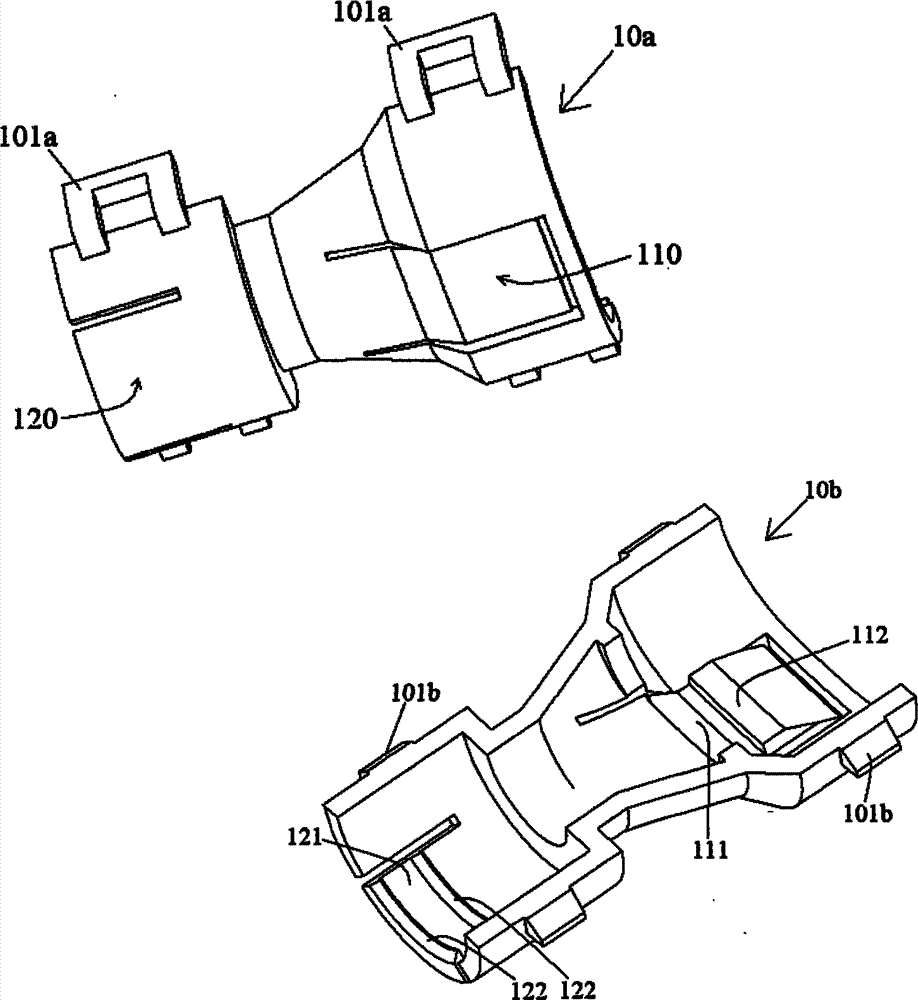
图1显示根据本发明的一个实例性的实施例的连接装置的两个半壳的示意图;Figure 1 shows a schematic diagram of two half-shells of a connecting device according to an exemplary embodiment of the present invention;
图2是由图1所示的两个半壳形成的整个壳体的剖视图,其显示第一部件插入连接装置的一端并与第一弹性卡扣锁扣在一起;Fig. 2 is a cross-sectional view of the whole housing formed by the two half-shells shown in Fig. 1, which shows that the first part is inserted into one end of the connection device and locked together with the first elastic buckle;
图3是由图1所示的两个半壳形成的整个壳体的剖视图,其显示第二部件插入连接装置的另一端并与第二弹性卡扣锁扣在一起;和Fig. 3 is a cross-sectional view of the whole housing formed by the two half-shells shown in Fig. 1, which shows that the second part is inserted into the other end of the connection device and locked together with the second elastic buckle; and
图4显示第二弹性卡扣的局部放大视图。Fig. 4 shows a partially enlarged view of the second elastic buckle.
具体实施方式 Detailed ways
下面通过实施例,并结合附图,对本发明的技术方案作进一步具体的说明。在说明书中,相同或相似的附图标号指示相同或相似的部件。下述参照附图对本发明实施方式的说明旨在对本发明的总体发明构思进行解释,而不应当理解为对本发明的一种限制。The technical solutions of the present invention will be further specifically described below through the embodiments and in conjunction with the accompanying drawings. In the specification, the same or similar reference numerals designate the same or similar components. The following description of the embodiments of the present invention with reference to the accompanying drawings is intended to explain the general inventive concept of the present invention, but should not be construed as a limitation of the present invention.
图1显示根据本发明的一个实例性的实施例的连接装置的两个半壳的示意图。Fig. 1 shows a schematic diagram of two half-shells of a connecting device according to an exemplary embodiment of the present invention.
如图1所示,在本发明的一个实例性的实施例中,连接装置主要包括第一半壳10a和第二半壳10b。该第一半壳10a和第二半壳10b能够以可拆卸的方式相互锁合在一起,形成一个完整的壳体10(参见图2和图3)。As shown in FIG. 1 , in an exemplary embodiment of the present invention, the connecting device mainly includes a
请参见图1,在图1所示的一个实例性的实施例中,在第一半壳10a的外表面上形成有至少一个卡槽101a,在第二半壳10b的外表面上形成有与至少一个卡槽101a锁扣在一起的至少一个卡扣凸起101b。这样,当第一和第二半壳10a、10b装配在一起时,就可以通过卡槽101a和卡扣凸起101b所形成的卡扣结构相互锁合在一起。当需要打开第一和第二半壳10a、10b时,只需向外扳动卡槽101a,使卡槽101a与卡扣凸起101b相互分离即可。Please refer to FIG. 1. In an exemplary embodiment shown in FIG. 1, at least one
请注意,本发明不局限于图1所示的一个具体的实例性的实施例,在本发明的另一个实例性的实施例中,可以在第一半壳10a上形成卡扣凸起101b,而在第二半壳10b上形成卡槽101a。Please note that the present invention is not limited to a specific exemplary embodiment shown in FIG. 1. In another exemplary embodiment of the present invention, a
当然,在本发明中,用于将第一和第二半壳10a、10b锁合在一起的锁合结构不局限于前述卡槽101a和卡扣凸起101b,也可以使用现有技术中的任一种合适的锁具,例如,环形夹具等。Of course, in the present invention, the locking structure for locking the first and second half-
请继续参见图1,在本发明的一个实例性的实施例中,除了卡槽101a和卡扣凸起101b之外,第一半壳10a和第二半壳10b的其它结构基本相同。Please continue to refer to FIG. 1 , in an exemplary embodiment of the present invention, except for the
如图1所示,每个半壳10a、10b的第一端形成有一个第一弹性卡扣110,每个半壳10a、10b的第二端形成有一个第二弹性卡扣120。这样,由第一和第二半壳10a、10b所形成的壳体10的第一端就会具有第一弹性卡扣110,由第一和第二半壳10a、10b所形成的壳体10的第二端就会具有第二弹性卡扣120。As shown in FIG. 1 , a first
图2是由图1所示的两个半壳10a、10b形成的整个壳体10的剖视图,其显示第一部件20插入连接装置的一端并与第一弹性卡扣110锁扣在一起。FIG. 2 is a cross-sectional view of the
如图1和图2所示,在本发明的一个实例性的实施例中,第一弹性卡扣110主要包括第一弹性悬臂111和第一卡钩112。As shown in FIGS. 1 and 2 , in an exemplary embodiment of the present invention, the first
如图1和图2所示,第一弹性悬臂111的朝内的基部与壳体10连接。第一卡钩112形成在第一弹性悬臂111的自由端。As shown in FIGS. 1 and 2 , the inward base of the first elastic cantilever 111 is connected to the
如图1和图2所示,在本发明的一个实例性的实施例中,第一卡钩112具有引导第一部件20插入的倾斜引导边112a。As shown in FIG. 1 and FIG. 2 , in an exemplary embodiment of the present invention, the
在图1和图2所示的一个具体的实例性的实施例中,尽管第一弹性卡扣110仅形成有一个第一卡钩112,但是,本发明不局限于此,例如,第一弹性卡扣110也可以具有多个第一卡钩112,该多个第一卡钩112可以沿第一弹性悬臂111的纵向前后间隔分布。In a specific exemplary embodiment shown in FIGS. 1 and 2, although the first
如图1和图2所示,每个半壳10a、10b上的第一弹性卡扣110一体地形成在各自的半壳10a、10b上,成为各自的半壳10a、10b的一部分,例如,通过模制的方法形成为一体件。As shown in Figures 1 and 2, the first
图3是由图1所示的两个半壳10a、10b形成的整个壳体10的剖视图,其显示第二部件30插入连接装置的另一端并与第二弹性卡扣120锁扣在一起。FIG. 3 is a cross-sectional view of the
如图1、图2和图3所示,在本发明的一个实例性的实施例中,第二弹性卡扣120主要包括第二弹性悬臂121和两个第二卡钩122,两个第二卡钩122沿第二弹性悬臂121的纵向前后间隔分布。As shown in Figure 1, Figure 2 and Figure 3, in an exemplary embodiment of the present invention, the second
如图1、图2和图3所示,第二弹性悬臂121的朝内的基部与壳体10连接。两个第二卡钩122形成在第二弹性悬臂121的自由端。As shown in FIG. 1 , FIG. 2 and FIG. 3 , the inwardly facing base of the second
图4显示第二弹性卡扣的局部放大视图。如图1、图2、图3和图4所示,在本发明的一个实例性的实施例中,每个第二卡钩122具有引导第二部件30插入的倾斜引导边122a。Fig. 4 shows a partially enlarged view of the second elastic buckle. As shown in FIG. 1 , FIG. 2 , FIG. 3 and FIG. 4 , in an exemplary embodiment of the present invention, each
在图1、图2、图3和图4所示的一个具体的实例性的实施例中,尽管第二弹性卡扣120仅形成有两个第二卡钩122,但是,本发明不局限于此,例如,第二弹性卡扣120也可以具有一个或三个以上的第二卡钩122。In a specific exemplary embodiment shown in Fig. 1, Fig. 2, Fig. 3 and Fig. 4, although the second
如图1、图2、图3和图4所示,每个半壳10a、10b上的第二弹性卡扣120一体地形成在各自的半壳10a、10b上,成为各自的半壳10a、10b的一部分,例如,通过模制的方法形成为一体件。As shown in Fig. 1, Fig. 2, Fig. 3 and Fig. 4, the second
如图2所示,在本发明的一个实例性的实施例中,第一部件20为连接器,该连接器的插入端上具有凸起212。当第一部件20插入壳体10的第一端时,第一弹性卡扣110与连接器的凸起212锁扣在一起。As shown in FIG. 2 , in an exemplary embodiment of the present invention, the first component 20 is a connector, and the insertion end of the connector has a protrusion 212 . When the first component 20 is inserted into the first end of the
如图3所示,在本发明的一个实例性的实施例中,第二部件30为波纹管,该波纹管的外周上具有齿状凸起312。当第二部件30插入壳体10的第二端时,第二弹性卡扣120与波纹管的齿状凸起312锁扣在一起。As shown in FIG. 3 , in an exemplary embodiment of the present invention, the
尽管未图示,在本发明的一个实例性的实施例中,第一和第二部件20、30可以均为连接器,每个连接器的插入端上具有凸起212,用于与第一和第二弹性卡扣110、120锁扣在一起。Although not shown, in an exemplary embodiment of the present invention, the first and
尽管未图示,在本发明的另一个实例性的实施例中,第一和第二部件20、30可以均为波纹管,每个波纹管的外周上具有齿状凸起312,用于与第一和第二弹性卡扣110、120锁扣在一起。Although not shown, in another exemplary embodiment of the present invention, the first and
需要说明的是,在本发明中,第一和/或第二部件20、30不局限于前述连接器或波纹管,也可以是其它类型的需要相互机械地连接的部件。It should be noted that, in the present invention, the first and/or
根据本发明的一个实例性的实施例,本发明还提供一种前述连接装置的使用方法,包括如下步骤:According to an exemplary embodiment of the present invention, the present invention also provides a method for using the aforementioned connecting device, including the following steps:
S10:将两个半壳10a、10b锁合在一起,形成一个完整的壳体10;和S10: locking the two
S20:将第一和第二部件20、30分别从壳体10的两端插入,从而实现第一和第二部件20、30的相互连接。S20: inserting the first and
在本发明的另一个实例性的实施例中,在前述步骤S20之后还可以包括步骤:In another exemplary embodiment of the present invention, after the aforementioned step S20, steps may also be included:
S30:打开相互锁合的两个半壳10a、10b,从而实现第一和第二部件20、30的相互分离。S30: Open the two interlocked half-
虽然结合附图对本发明进行了说明,但是附图中公开的实施例旨在对本发明优选实施方式进行示例性说明,而不能理解为对本发明的一种限制。Although the present invention has been described with reference to the accompanying drawings, the embodiments disclosed in the accompanying drawings are intended to illustrate preferred embodiments of the present invention and should not be construed as a limitation of the present invention.
虽然本总体发明构思的一些实施例已被显示和说明,本领域普通技术人员将理解,在不背离本总体发明构思的原则和精神的情况下,可对这些实施例做出改变,本发明的范围以权利要求和它们的等同物限定。While certain embodiments of the present general inventive concept have been shown and described, it will be understood by those of ordinary skill in the art that changes may be made to these embodiments without departing from the principles and spirit of the present general inventive concept. The scope is defined by the claims and their equivalents.
Claims (16)
Priority Applications (1)
| Application Number | Priority Date | Filing Date | Title |
|---|---|---|---|
| CN2011101148430A CN102758819A (en) | 2011-04-28 | 2011-04-28 | Connecting device |
Applications Claiming Priority (1)
| Application Number | Priority Date | Filing Date | Title |
|---|---|---|---|
| CN2011101148430A CN102758819A (en) | 2011-04-28 | 2011-04-28 | Connecting device |
Publications (1)
| Publication Number | Publication Date |
|---|---|
| CN102758819A true CN102758819A (en) | 2012-10-31 |
Family
ID=47053409
Family Applications (1)
| Application Number | Title | Priority Date | Filing Date |
|---|---|---|---|
| CN2011101148430A Pending CN102758819A (en) | 2011-04-28 | 2011-04-28 | Connecting device |
Country Status (1)
| Country | Link |
|---|---|
| CN (1) | CN102758819A (en) |
Cited By (2)
| Publication number | Priority date | Publication date | Assignee | Title |
|---|---|---|---|---|
| CN104916494A (en) * | 2015-06-26 | 2015-09-16 | 贵州新安航空机械有限责任公司 | Anti-deformation movable iron core press-fitting structure |
| CN110049812A (en) * | 2016-12-07 | 2019-07-23 | 德国古斯塔夫·爱立许机械制造有限公司 | The method of hybrid blade with anti-wear component and the base part for anti-wear component to be attached to hybrid blade |
Citations (7)
| Publication number | Priority date | Publication date | Assignee | Title |
|---|---|---|---|---|
| US5422437A (en) * | 1993-04-16 | 1995-06-06 | Hubbell Incorporated | Electrical connector assembly |
| JPH1084611A (en) * | 1996-09-10 | 1998-03-31 | Sumitomo Wiring Syst Ltd | Joint member of corrugated tube for covering wire harness |
| JP2000013950A (en) * | 1998-06-17 | 2000-01-14 | Yazaki Corp | Corrugated tube fixture |
| EP1322011A1 (en) * | 2001-12-21 | 2003-06-25 | JVK Plastics, naamloze vennootschap | Flush-mounted box for electrical elements |
| JP2007043809A (en) * | 2005-08-02 | 2007-02-15 | Mirai Ind Co Ltd | Pipe connection structure of pipe connection, wiring box and pipe joint |
| CN101405050A (en) * | 2006-09-21 | 2009-04-08 | 科维蒂恩股份公司 | Safety connector assembly |
| CN101764381A (en) * | 2008-12-25 | 2010-06-30 | 矢崎总业株式会社 | Holder |
-
2011
- 2011-04-28 CN CN2011101148430A patent/CN102758819A/en active Pending
Patent Citations (7)
| Publication number | Priority date | Publication date | Assignee | Title |
|---|---|---|---|---|
| US5422437A (en) * | 1993-04-16 | 1995-06-06 | Hubbell Incorporated | Electrical connector assembly |
| JPH1084611A (en) * | 1996-09-10 | 1998-03-31 | Sumitomo Wiring Syst Ltd | Joint member of corrugated tube for covering wire harness |
| JP2000013950A (en) * | 1998-06-17 | 2000-01-14 | Yazaki Corp | Corrugated tube fixture |
| EP1322011A1 (en) * | 2001-12-21 | 2003-06-25 | JVK Plastics, naamloze vennootschap | Flush-mounted box for electrical elements |
| JP2007043809A (en) * | 2005-08-02 | 2007-02-15 | Mirai Ind Co Ltd | Pipe connection structure of pipe connection, wiring box and pipe joint |
| CN101405050A (en) * | 2006-09-21 | 2009-04-08 | 科维蒂恩股份公司 | Safety connector assembly |
| CN101764381A (en) * | 2008-12-25 | 2010-06-30 | 矢崎总业株式会社 | Holder |
Cited By (3)
| Publication number | Priority date | Publication date | Assignee | Title |
|---|---|---|---|---|
| CN104916494A (en) * | 2015-06-26 | 2015-09-16 | 贵州新安航空机械有限责任公司 | Anti-deformation movable iron core press-fitting structure |
| CN110049812A (en) * | 2016-12-07 | 2019-07-23 | 德国古斯塔夫·爱立许机械制造有限公司 | The method of hybrid blade with anti-wear component and the base part for anti-wear component to be attached to hybrid blade |
| CN110049812B (en) * | 2016-12-07 | 2021-11-16 | 德国古斯塔夫·爱立许机械制造有限公司 | Hybrid blade with wear resistant element and method for attaching wear resistant element to base portion of hybrid blade |
Similar Documents
| Publication | Publication Date | Title |
|---|---|---|
| AU2013356885B2 (en) | Dust-proof apparatus and fiber optic connector assembly | |
| TW202115447A (en) | Fiber optic connector assemblies with adjustable polarity | |
| JP2017520887A (en) | Electrical outlet with locking mechanism | |
| CN205657255U (en) | Connector | |
| JP3161161U (en) | Electrical connector | |
| US8287298B2 (en) | Detachment-preventing plug | |
| CN102758819A (en) | Connecting device | |
| US8164913B2 (en) | Fastener and electronic device having the same | |
| CN102032533A (en) | Housing connection structure and LED lamp housing having same | |
| CN102882062A (en) | Communication plug | |
| JP3162759U (en) | Electrical connector assembly | |
| JP2012068529A (en) | Optical connector | |
| US8986035B2 (en) | Securing member for a connector | |
| CN114520435B (en) | Adapters, plug connector assemblies, and connector assemblies | |
| US20110269004A1 (en) | Battery lock structure for electronic device | |
| CN103636079B (en) | Lever-type connector | |
| CN102214872B (en) | Connector component | |
| CN102238818B (en) | Shell clamping structure | |
| TWI433411B (en) | Fixing structure and fixing assembly using the same | |
| TWM513608U (en) | Connection buckle | |
| CN105164864A (en) | Connector | |
| CN211789803U (en) | Connector and plug thereof | |
| CN205452683U (en) | Locking fixed buckle that takes off of electric connector | |
| JP2005019070A (en) | Lock device | |
| US20130273763A1 (en) | Detachable connector |
Legal Events
| Date | Code | Title | Description |
|---|---|---|---|
| C06 | Publication | ||
| PB01 | Publication | ||
| C10 | Entry into substantive examination | ||
| SE01 | Entry into force of request for substantive examination | ||
| C02 | Deemed withdrawal of patent application after publication (patent law 2001) | ||
| WD01 | Invention patent application deemed withdrawn after publication |
Application publication date: 20121031 |