CN102741585A - Indicating puller - Google Patents
Indicating puller Download PDFInfo
- Publication number
- CN102741585A CN102741585A CN201080050408XA CN201080050408A CN102741585A CN 102741585 A CN102741585 A CN 102741585A CN 201080050408X A CN201080050408X A CN 201080050408XA CN 201080050408 A CN201080050408 A CN 201080050408A CN 102741585 A CN102741585 A CN 102741585A
- Authority
- CN
- China
- Prior art keywords
- directional indicator
- chain
- pull
- pull chain
- puller wire
- Prior art date
- Legal status (The legal status is an assumption and is not a legal conclusion. Google has not performed a legal analysis and makes no representation as to the accuracy of the status listed.)
- Pending
Links
Images


Classifications
-
- E—FIXED CONSTRUCTIONS
- E06—DOORS, WINDOWS, SHUTTERS, OR ROLLER BLINDS IN GENERAL; LADDERS
- E06B—FIXED OR MOVABLE CLOSURES FOR OPENINGS IN BUILDINGS, VEHICLES, FENCES OR LIKE ENCLOSURES IN GENERAL, e.g. DOORS, WINDOWS, BLINDS, GATES
- E06B9/00—Screening or protective devices for wall or similar openings, with or without operating or securing mechanisms; Closures of similar construction
- E06B9/24—Screens or other constructions affording protection against light, especially against sunshine; Similar screens for privacy or appearance; Slat blinds
- E06B9/26—Lamellar or like blinds, e.g. venetian blinds
- E06B9/28—Lamellar or like blinds, e.g. venetian blinds with horizontal lamellae, e.g. non-liftable
- E06B9/30—Lamellar or like blinds, e.g. venetian blinds with horizontal lamellae, e.g. non-liftable liftable
- E06B9/32—Operating, guiding, or securing devices therefor
- E06B9/326—Details of cords, e.g. buckles, drawing knobs
-
- E—FIXED CONSTRUCTIONS
- E06—DOORS, WINDOWS, SHUTTERS, OR ROLLER BLINDS IN GENERAL; LADDERS
- E06B—FIXED OR MOVABLE CLOSURES FOR OPENINGS IN BUILDINGS, VEHICLES, FENCES OR LIKE ENCLOSURES IN GENERAL, e.g. DOORS, WINDOWS, BLINDS, GATES
- E06B9/00—Screening or protective devices for wall or similar openings, with or without operating or securing mechanisms; Closures of similar construction
- E06B9/56—Operating, guiding or securing devices or arrangements for roll-type closures; Spring drums; Tape drums; Counterweighting arrangements therefor
- E06B9/78—Operating, guiding or securing devices or arrangements for roll-type closures; Spring drums; Tape drums; Counterweighting arrangements therefor for direct manual operation, e.g. by tassels, by handles
- E06B2009/785—Operating, guiding or securing devices or arrangements for roll-type closures; Spring drums; Tape drums; Counterweighting arrangements therefor for direct manual operation, e.g. by tassels, by handles by belts, straps, bands, tapes, cords, tassels
Landscapes
- Engineering & Computer Science (AREA)
- Structural Engineering (AREA)
- Architecture (AREA)
- Civil Engineering (AREA)
- Decoration Of Textiles (AREA)
- Illuminated Signs And Luminous Advertising (AREA)
Abstract
本发明涉及一种为了装置的期望操作而表明牵拉线的牵拉方向的牵拉线,所述牵拉线包括方向性指示部,其由颜色变化、纹理变化以及二者的组合而形成,从而为这种装置的期望的操作指示牵拉方向。
The present invention relates to a pull wire for indicating the pulling direction of the pull wire for the desired operation of the device, the pull wire comprising a directional indicator formed by color change, texture change or a combination thereof, thereby indicating the pulling direction for the desired operation of the device.
Description
Technical field
The present invention relates to drag wire change in color or texture variations, it is used for device operation, with direction indication and more particularly indicate direction of draw.
Background technique
Curtain adopts drag wire, for example stay cord, loop chain, pelletron or ball chain substantially, so that a series of lath rotation vertical or level perhaps opens or closes curtain.Through leading one side of drag wire, lath is along a direction, for example to right rotation, and perhaps venetian blind or heavy curtain are opened.Through leading the another side of drag wire, lath is along opposite direction, for example to anticlockwise, and perhaps venetian blind or heavy curtain are closed.Some curtain has the drag wire that is anchored on ground, wall or the window frame, thereby drag wire can be by pulling up or down, with the operation curtain.
Yet, the user do not know drag wire which side will carry out desired operation.The user must select on one side randomly, and with the operation of confirming through this limit of tractive to carry out, wherein this operation might not be desired operation.The motion of the final non-expectation of curtain has caused the user dejected and lose time.
Except making that the operator is dejected, the incorrect drag wire of tractive cause curtain mechanism unnecessary wearing and tearing and tear.For example, if curtain is opened fully, the tractive on the then wrong drag wire makes drag wire and mechanism stressed, and this is because curtain can not move in response to downward pulling force.
In addition, the user in the user of some Her Vision Was Tied Down or the dark room is difficult to observe drag wire, and some user is difficult to grasp drag wire.
Additionally, exist other device for example machinery and light fixture operate by drag wire, to make that the user operates dejected owing to lacking the directivity indicator for this.
Summary of the invention
Embodiments of the invention provide a kind of tractive chain that indicates the direction of draw of tractive chain for the desired operation of installing.Said tractive chain comprises: a plurality of pearls, and it comprises: the pearl of first kind; And the pearl of second kind; A plurality of handles that connect, it comprises: company's handle of first kind, company's handle of said first kind is connected to the pearl of said first kind pearl of second kind.The pearl of at least the first kind comprises and is positioned at its lip-deep directivity indication portion that it forms through change in color, texture variations and the combination of the two, so that be the operation indication direction of draw of the expectation of device.
The pearl of first kind comprises episphere and lower semisphere, and directivity indication portion comprises outward appearance or the texture episphere different with said lower semisphere.Each pearl in said a plurality of pearl comprises said directivity indication portion.The color of the pearl of said first kind is different with the pearl of said second kind.Directivity indication portion comprises the lower semisphere with second color of pearl of the episphere with first color and said first kind of the pearl of said first kind.
Directivity indication portion comprises episphere of the pearl that at least one is positioned at said first kind or the depression on the lower semisphere.Directivity indication portion is processed by anti-slip material.Directivity indication portion has color gradient.Directivity indication portion comprises episphere of the pearl that is positioned at said first kind or the object on the lower semisphere.Directivity indication portion comprises decorative pattern.Directivity indication portion comprises arrow.Directivity indication portion is etched in the surface of pearl of said first kind.Directivity indication portion comprises circle.Directivity indication portion comprises raised portion.Directivity indication portion is luminous in the dark.Directivity indication portion is illuminated.
Directivity indication portion comprises around the cover of the pearl of said first kind.Said cover is transparent.Said cover centers at least: the pearl of the pearl of said first kind, said second kind and the said handle that connects.The change in color of said cover.The texture variations of said cover.Said tractive chain also comprises the pearl of the third type, and said cover is at least around the pearl of said first kind and the pearl of said the third type, so that the pearl of the pearl of said first kind and said the third type links to each other through said cover.
Before said tractive chain is assembled, on the pearl of said first kind, realize color or texture variations.After said tractive chain is assembled, on the pearl of said first kind, realize color or texture variations.
First section of said tractive chain comprises that first section that indicates the said tractive chain of tractive will cause first party tropism's indication portion of first operation of device; Second section of said tractive chain comprises that second section that indicates the said tractive chain of tractive will cause second party tropism's indication portion of second operation of device.
Directivity indication portion is positioned on the pearl at interval.Directivity indication portion is positioned at least one and connects on the handle.
Another embodiment of the present invention provides a kind of drag wire that indicates the direction of draw of drag wire for the desired operation of installing.Said drag wire comprises directivity indication portion, and wherein said directivity indication portion is formed by change in color, texture variations and the combination of the two, thereby is the operation indication direction of draw of the expectation of device.
Said drag wire comprises pelletron, and wherein said pelletron comprises: a plurality of pearls, and it comprises the pearl of first kind and the pearl of second kind; And a plurality of handles that connect, it comprises company's handle of first kind, and company's handle of said first kind is connected to the pearl of said first kind pearl of said second kind.The pearl of said at least first kind comprises directivity indication portion.
Drag wire can be a stay cord.Drag wire can be a loop chain.
Directivity indication portion can be the cover around drag wire.
First section of said drag wire comprises that first section that indicates the said drag wire of tractive will cause first party tropism's indication portion of first operation of device; Second section of said drag wire comprises that second section that indicates the said drag wire of tractive will cause second party tropism's indication portion of second operation of device.
Another embodiment of the present invention provides a kind of directivity indication portion has been positioned at the method on the drag wire that is used for device.Said method comprises: drag wire is positioned at a neutral position, so that device is in the intermediateness between opening and closing; The location is opened directivity indication portion and is in the position that is easy to grasp on first section of drag wire; And locating closing directivity indication portion is in similar position on second section of drag wire.
First handle also can comprise directivity indication portion.
Directivity indication portion can be positioned the place, end of drag wire.
Another embodiment of the present invention provides a kind of method that directivity indication portion is positioned on the ring formula tractive chain that is used for device; Said tractive chain comprises a plurality of pearls, and each pearl has the first half ones and the second half ones, and said method comprises: directivity indication portion is applied to said a plurality of pearl; Said directivity indication portion comprises said the first half ones; The outward appearance of wherein said the first half ones or texture are different with said the second half ones, so that on first limit of said tractive chain, the first half ones are positioned on the second half ones; And on second limit of said tractive chain, the second half ones are positioned on the first half ones.
It is a kind of in the method that comprises orientation property indication portion on the tractive chain of a plurality of pearls that another embodiment of the present invention provides; Said method comprises: said tractive chain is carried out the cutting first time, so that said tractive chain comprises first cutting tip and second cutting tip; Said first cutting tip is connected to the first end of first party tropism indication portion; And said second cutting tip is connected to the second end of said first party tropism's indication portion.
This method also comprises: said tractive chain is carried out the cutting second time, so that said tractive chain also comprises the 3rd cutting tip and the 4th cutting tip; Said the 3rd cutting tip is connected to the first end of second party tropism indication portion; And said the 4th cutting tip is connected to the second end of said second party tropism's indication portion.
Said first party tropism's indication portion comprises holder, and said holder is suitable for receiving at least two pearls in a plurality of pearls of said tractive chain.
It is a kind of in the method that is used for orientation property indication portion on the stay cord of device that another embodiment of the present invention provides; Length along said stay cord comprises directivity indication portion; Said method comprises: said stay cord is connected to device; So that the indication first direction of the directivity indication portion on first limit of said stay cord; And the indication of the directivity indication portion on second limit of the said stay cord second direction opposite with said first direction, first limit of the said stay cord of tractive makes carries out first operation on said device, and second limit of the said stay cord of tractive makes that on said device, carrying out second operates.
Description of drawings
Fig. 1 is the side view of tractive chain according to an embodiment of the invention;
Fig. 2 A is the perspective view of tractive chain according to another embodiment of the present invention;
Fig. 2 B is the perspective view of tractive chain according to another embodiment of the present invention;
Fig. 2 C is the perspective view of tractive chain according to another embodiment of the present invention;
Fig. 2 D is the perspective view of tractive chain according to another embodiment of the present invention;
Fig. 3 A is the perspective view that on ball or pearl, has the tractive chain of designated symbol according to an embodiment of the invention;
Fig. 3 B is the perspective view of the tractive chain that on ball or pearl, has designated symbol according to another embodiment of the present invention;
Fig. 4 is the perspective view that adopts the tractive chain of the texture that applies according to an embodiment of the invention;
Fig. 5 A is the side view that adopts the tractive chain of cover according to an embodiment of the invention;
Fig. 5 B is the side view of the tractive chain of employing cover according to another embodiment of the present invention;
Fig. 6 A is the front elevation that has the tractive chain of safety installations according to an embodiment of the invention;
Fig. 6 B is the side view of the tractive chain with safety installations of Fig. 6 A;
Fig. 7 A is the side view of stay cord according to another embodiment of the present invention;
Fig. 7 B is the side view of loop chain according to another embodiment of the present invention;
Fig. 8 A is the sectional view of stay cord according to another embodiment of the present invention;
Fig. 8 B is the side view of the stay cord of Fig. 8 A;
Fig. 9 is the side view of tractive chain according to another embodiment of the present invention;
Figure 10 is the side view of tractive chain according to another embodiment of the present invention;
Figure 11 is the side view of stay cord according to another embodiment of the present invention;
Figure 12 is the side view of stay cord according to another embodiment of the present invention; And
Figure 13 is the side view of tractive chain according to another embodiment of the present invention.
Embodiment
Will be in conjunction with the detailed description that proposes below the accompanying drawing as being used for according to the variable embodiment's of the color of drag wire of the present invention and/or texture explanation and will not embodying unique form that the present invention can be configured or adopt.It should be understood that function same or that be equal to and structure can be through also will realizing in the different embodiments of spirit of the present invention and encompasses.
Shown in Fig. 1 to 4, on such as the tractive chain of pelletron or ball chain, adopt color or texture variations, with provider tropism's indication portion, should be pulled to operate the direction of curtain or other device as expected with indication tractive chain.In an embodiment of the present invention, texture or change in color are implemented with non-homogeneous or nonequilibrium mode, thereby the interhemispheric difference in up and down of pearl or ball is provided.Texture or change in color can be used so that the user can observe or which limit of perception tractive tractive chain, realizing desired effects, thereby open or close window or such as the device of level or " mini " blind, vertical louver curtain or heavy curtain.The user can through the correct limit of tractive chain promptly and up or down tractive tractive chain open or close curtain or other device.
Fig. 1 shows the tractive chain 10 of a segment length.Tractive chain 10 is by straight and through connecting rod (link) or connect spheroidal pearl or the ball 12 that handle (shank) 14 is connected with each other and form.Pearl 12 can be formed the hollow metal ball, and this hollow metal ball has opening at top and at.This pearl 12 is connected with each other through metal connecting rod 14 then, and wherein said metal connecting rod has the enlarged end that in the opening in opposite directions of adjacent pearl 12, receives.The diameter of enlarged end is greater than the diameter of this opening, thereby pearl 12 is hunted down on the end of connecting rod 14.Alternatively, pearl 12 can be formed and the rope setting of edge one segment length discontinuously by plastics, and wherein said rope can be processed by braided fiber.Can also adopt other method of the chain that forms the pearl 12 that links to each other.Each pearl can also have other shape except sphere.
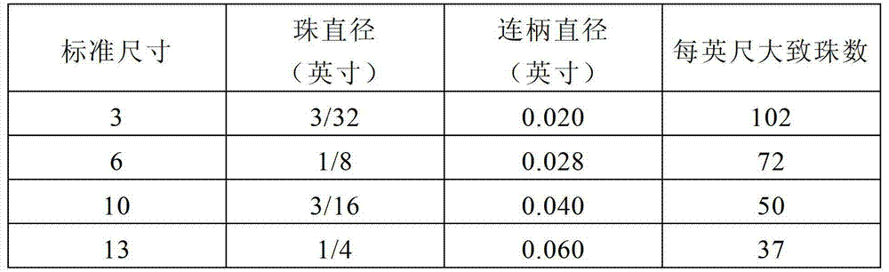
For example, although pelletron has multiple different size, below list the several criteria size.
In the embodiment shown in fig. 1, the episphere 16 of each pearl 12 is light.The lower semisphere 18 of each pearl 12 is dark.The difference of this color provides visible signal for the user, thereby will open curtain or other device towards the hemisphere pulling chain 10 of light color in the upward direction, and will close curtain or other device towards the hemisphere pulling tractive chain 10 of dark color in a downward direction.Various color combination, for example in vain to black or yellowly can be used to create difference as shown in Figure 1 to dark blue.In addition, needn't provide from light color to dark transition through tangible line.In fact, can be little by little from a kind of color transition to another kind of color.
The direction sensing portion that adopts distinguishing texture also can realize Fig. 1 for pearl hemisphere 16,18.Distinguishing texture can as above change to distinguishing color is such.In addition; Distinguishing textured pattern can be used uniquely; To the user sense of touch (tactile) signal to be provided with more delicate visible signal, perhaps the texture difference can adopt with color distinction with combining, with strong visible signal haptic signal to be provided.
Visible signal that on pearl 12, is adopted or texture signal also need not to be from shallow to dark or from being smoothed to coarse simple transition.In fact, various non-uniform patterns can be used, and on the hemisphere of pearl, distinguished vision and/or sensation is provided.Fig. 2 A to 2D shows the different feasible pattern that can adopt.Pattern shown in Fig. 2 A to 2D is not comprehensive.In fact, those skilled in the art will know that a large amount of different patterns can be used, and help to point out the direction of tractive tractive chain 10.
For example, Fig. 2 A shows the band or the visual circle of the dark color on the episphere of light pearl 12.In another example, Fig. 2 B shows the thread pattern of the dark color on the episphere of light pearl 12.Another instance shown in Fig. 2 C has the light triangle on the episphere that is positioned at dark pearl 12.In addition, Fig. 2 D shows the band or the visual circle of the light color on the episphere that is positioned at dark pearl 12.
The all right symbolization of optical signal, the for example arrow that are used for direction indication.Fig. 3 A shows embodiments of the invention, and therein, arrow is marked on the outer surface of pearl 12.Fig. 3 B shows optional embodiment, and therein, opening (also can be recess) 20 has been stamped out on pearl 12, and its mode is for to form arrow on pearl 12.Other structure also can be 20 employings of opening.Star-shaped openings, moon shape opening etc. can be used.Symbol except arrow can be used.The symbol of multiple alternate manner also can be incorporated in the pearl 12.For example, symbol can be etched on the surface of pearl 12, and is bonding or otherwise be connected to the outer surface of pearl 12, perhaps be embedded in the pearl 12, and symbol can be luminous in the dark.
Vision and texture distinctiveness pattern can also be formed through the outer surface that will glisten cosmetic sheet or synthetic diamond are applied to pearl 12.Fig. 4 shows a kind of pearl, and therein, synthetic diamond 22 has been applied to the episphere of pearl 12.Other distinctiveness element also can be used.The distinctiveness element can also be employed with various different patterns and/or symbol, to indicate the direction of operation tractive chain 10.
When pearl or ball were made or used by the later stage, texture variations or texture classification can be formed.Structure can be plastics or metal.
In an embodiment of the present invention, after making, visual or texture indication portion is brushed or is sprayed on the hemisphere.If necessary, said indication portion can be any other suitable material, for example composite material, reclaiming material, silicone or latex.In other embodiments of the invention, decorate texture or painted can be other shape, include but not limited to arrow, ellipse or circular perhaps multiaspect shape.
Indication portion can also or be marked on the pearl 12 by engraving, perhaps by the groove indication that on pearl 12, forms.
Indication portion can be stamped on the pearl 12.
Indication portion can also be provided with on two hemisphere of pearl 12, and the indication portion of each hemisphere is different with the indication portion of another hemisphere, to point the direction.
Colored pattern on the pearl 12 or any other directional patterns can be applied to pearl 12 in the tractive chain 10 of whole length.Alternatively, colored pattern can be applied to pearl 12 at interval, for example whenever apply colored pattern at a distance from a pearl, and has enough regularity, so that whole pattern still can be seen by the user.In another optional embodiment, might the time grasp the position of tractive chain 10 along whole tractive chain 10 in operation the user, colored pattern can be applied to the pearl 12 of selecting length.
According to another embodiment of the present invention, the indication hemisphere of tractive chain 10 can also have circle, and wherein said circle is thicker in that side as the indication portion of pearl of hemisphere.Circle can also be processed by material luminous in the dark, indicates so that further directivity to be provided.
According to another embodiment of the present invention, circle can have the diameter of variation at the opening of the axle head of pearl, thereby said circle can not cover whole hemisphere.
In the embodiment who substitutes, the one outer surface of pearl 12 can be made up of anti-slip material.In addition, softer plastics or anti-slip material can not cover the whole outer surface of tractive chain 10, and can be with the mode of slivering, be formed on the tractive chain 10 with the mode of circumference ridge or with other pattern.
In another embodiment of the present invention; Coming into the picture of tractive chain 10 has the first indication portion with first section of operating curtain or other device; This first indication portion is positioned at least one pearl 12, for example for phrase, arrow, spine or point indicating tractive chain 10 to be pulled up or down to the user, with operation curtain or other device, for example rise cord along specific direction.Second section of tractive chain 10 has the second indication portion; This second indication portion is positioned at least one pearl 12, for example is that phrase, arrow, spine or point are to indicate tractive chain 10 to be pulled up or down along specific direction to the user; Thereby operate curtain or other device with opposite mode, for example reduce cord.Thereby after the user confirmed tractive chain 10 should which direction of tractive for proper operation, tractive chain 10 can be assembled with the directivity indication portion that points to correct direction.
In another embodiment of the present invention, on tractive chain 10, can comprise raised portion, to show direction.The shape of raised portion can be any suitable shape, for example circle or arrow-shaped.
Shown in Fig. 5 A, through covering or overlap 24 attached on one or more pearls 12, distinguishing pattern of vision or symbol also can be applied to one or more pearls 12.In this embodiment, pattern or symbol are positioned at cover or overlap on 24.Textured pattern, color gradient or symbol also can put employing.Fig. 5 A shows the cover 24 that is applied in attached on a plurality of pearls 12.Cover 24 as shown is transparent, so that the relation of each element is described, still this cover is also nonessential is transparent.
Usually must tractive chain 10 be formed a ring for use in blind system or other device.In order to produce this ring, each end of pelletron is connected with each other.One embodiment has been shown in Fig. 5 B, and wherein, the cover 24 that is used to provider tropism's indication portion also is used for each end of tractive chain 10 is kept together.
According to the another embodiment of the present invention shown in Fig. 5 A and 5B, cover 24 can be to be processed by foam, rubber, composite material or other suitable material.At this, after tractive chain 10 was assembled, cover 24 can be positioned around tractive chain 10, and perhaps tractive chain 24 can be fixed to portions each section of tractive chain 10, still was positioned on the tractive chain 10 thereby when tractive chain 10 is disassembled, overlap 24.Cover material can be selected to grip surface or the non skid matting that provides softer.Because some tractive chain 10 is by belt wheel mechanism or other safety installations anchoring (the following detailed description), can be configured to be enough elasticity and durable so overlap 24, so that be not pulled through the mechanism of these types with damaging.
In another example; Cover 24 can be the shell that is formed by transparent material, for example plastics, and can be around the tractive chain 10 of a segment length, around pearl, around connecting handle (or the link between the pearl) or being positioned around a plurality of handles (or the link between the pearl) that connect.Transparent material can be rigid plastics or can be flexiplastic.Transparent material can also combine painted or decorative element for example coloured dye or paillette.These decorative elements can be arranged to indicate the direction that tractive chain 10 should be pulled.
In another embodiment of the present invention, the tractive chain 10 of a segment length can comprise the tractive chain section and the dark tractive chain section of light color.According to this embodiment of the invention, the user should tractive the tractive chain section of light color, to open curtain or other device, raise cord or make venetian blind rotate to open position for example.The user should tractive dark tractive chain section, to close curtain or other device, for example to reduce cord or make venetian blind rotate to closed position.
In another embodiment of the present invention, along tractive chain 10 from shallow to having the luminous in the dark classification of color grading or material deeply.This provides signal for the user, dark section that promptly should tractive tractive chain 10 with the shallow section that carries out closing operation and tractive tractive chain 10 to carry out opening operation.
In another embodiment of the present invention, tractive chain 10 can have the gradual change of luminescent material from the color gradient from light color to the dark color of the opposite end of an end to the tractive chain 10 of tractive chain 10 or dark.For example, after tractive chain 10 was positioned, one side of pelletron can show had the color more shallow than the another side of tractive chain.At this, chain can be fixed to static object, for example ground or a window frame, and this is to realize through tractive chain 10 being curled up the belt wheel or any suitable device that are connected to static object.According to this embodiment of the invention, the user should be along the direction tractive tractive chain 10 of the more shallow color of tractive chain 10, tractive tractive chain 10 upwards in this example, to open cord or venetian blind.The user should be along the direction tractive tractive chain 10 of the darker color of tractive chain 10, tractive tractive chain 10 downwards in this example, to close cord or venetian blind.
Material luminous in the dark processed or be coated with to the painted or texture of two hemisphere on the tractive chain 10 can also by material luminous in the dark, perhaps has the gradual change of material luminous in the dark.
Alternatively, tractive chain 10 can be processed and luminous in the dark make watched easily by fiber optic materials.
In another embodiment of the present invention, tractive chain 10 can be retrofited to obtain the outward appearance of expectation with other mode.For example, the hemisphere of the pearl 12 on the tractive chain 10 can be decorated by the element of quartzy or other any veining.In addition, tractive chain 10 is can color different, so that obtain the outward appearance of expectation, perhaps tractive chain 10 can be formed by transparent material, for example propylene esters polymer such as lucite.
In another embodiment of the present invention, pearl 12 can be transparent but have opaque integrative-structure or symbol, for example lightning, flower or arrow.
Those skilled in the art are with clear, and each pearl of tractive chain can be formed the multiple different shape that is applicable to different application.For example, each pearl can be shaped as arrow, dumbbell, ball, football or animal or move graphic shape.
In another embodiment of the present invention, tractive chain 10 can be adjusted, for example be used to operate warehouse gate or produce machine to being used for commercial Application.For example, a pair of tractive chain (one of them tractive chain is redness for green and another tractive chain) can be used to operate warehouse gate, thereby the green tractive chain of tractive is opened door and the red tractive chain of tractive cuts out door.In another example, the green tractive chain of tractive can begin to open a machine, and the red tractive chain of tractive can stop a machine.
In another embodiment of the present invention, tractive chain 10 can be colored as redness, with show this tractive chain can be in emergency, for example in emergent chemical shower, be used.
In another embodiment of the present invention, it is reflective for the situation of expectation light or reflection perhaps that one or two hemisphere of tractive chain 10 can luminous, for example utilize LED light fixture or other suitable light source luminescent.
In other embodiments of the invention, tractive chain 10 can be formed by multiple material.For example, tractive chain 10 can by rigid plastics form and have by rubber material form in case grasp easily tractive chain 10 such as the section that grasps bar.
In another embodiment of the present invention, referring to Fig. 6 A and 6B, the safety installations 50 of the Universal Cord Tensioner by name that for example can be bought by Hunter Douglas can adopt tractive chain 10.At this, safety installations 50 can be mounted to wall or other fixing surface through spring-loaded mounting bracket 52.Tractive chain 10 passes the opening 51 in the body of safety installations 50.When on tractive chain 10, not having pressure, pressing side of pearl 12 or the connecting rod 14 on many sides, moving to prevent tractive chain 10 with groove 56 in the latch piece 54 that spring-loaded mounting bracket links to each other.Yet no matter when tractive chain 10 is strained at, and the body of safety installations 50 is always upwards drawn with respect to fixing spring-loaded mounting bracket 52.Spring-loaded mounting bracket 52 is pulled to latch piece 54 downwards, thereby pearl 12 is released and tractive chain 10 can move through opening 51 then from groove 56, so that draw up or down.At this, the directivity indication portion on the tractive chain 10 is firm as to be enough to make the pressure of groove 56 and latch piece 54 can not make the directivity indication portion of removing.The size of directivity indication portion and structure also should be arranged to this directivity indication portion and can cooperate easily through opening 51.
In another embodiment shown in Fig. 7 A of the present invention, directivity indication portion 70 can be combined or by built-in (for example passing through weaving) in stay cord 71,72, wherein said stay cord can be for example cotton by any suitable material, nylon or plastics form.For example, indication portion 70 can be the braided wire of the dark color in the stay cord 71,72 of light color as shown in the figure or the braided wire of the light color in the dark stay cord.In addition, indication portion 70 and/or stay cord 71,72 can be to be processed by material luminous in the dark or metallic material.Indication portion 70 can also have different shapes, for example arrow or phrase.As alternatively, can reel stay cord or compile of directivity indication portion around stay cord.
At this; Stay cord 71,72 can use by the belt wheel on horizontal louvres; Thereby cause the front edge of the lath of venetian blind to rise the downward tractive of first section of stay cord 72; As being directed upwards towards by the directivity indication portion 70 in this section, and second section of tractive stay cord 71 causes the front edge of the lath of venetian blind to descend, as being pointed to downwards by the directivity indication portion in this section 70.As alternatively, the end of stay cord 71,72 can also be unclamped, thereby the end does not link to each other.
In another embodiment of the present invention, the indication portion on the stay cord can be a color gradient or by material gradual change luminous in the dark, thereby the part of stay cord has another part different appearance with stay cord.
Among described another embodiment, on pelletron 91,92, can adopt indication portion 94 in a similar manner as described above like Fig. 9 of the present invention, wherein each pearl 92 is positioned on the rope 93.At this, indication portion 94 can see between each pearl 92 on rope 93.In addition, rope links to each other if pearl passes through to connect handle, and then indication portion can be positioned at and connect on the handle.As alternatively, indication portion 103 can be arranged on wiring or connect handle 101 on the circle between the pearl 100 102, and is shown in figure 10.At this, circle 102 can be bundled in, is fastened on, tied up to or be fixed on rope in any suitable manner or connect on the handle 101.In addition, circle 102 can be processed by ribbon, silicon or any other suitable material.In addition, circle can comprise crystal, diamante perhaps can be luminous in the dark.
In another embodiment of the present invention, drag wire can be used for vertical blind, thereby downward tractive causes venetian blind along a direction rotation on one side of drag wire, and downward tractive makes venetian blind rotate along other direction on the another side of drag wire.
In another embodiment of the present invention; Drag wire can be used to open and close curtain (but not making venetian blind rotate); Thereby tractive makes curtain open downwards on one side of drag wire, and downward tractive makes curtain close on the another side of drag wire.
In another embodiment of the present invention, cover 24 as described above can be by adjustment to be used on stay cord.At this, the width of cover will equal the thickness of stay cord.In addition, cover can adopt to cover 24 aforesaid any characteristics.
In another embodiment shown in Fig. 7 B of the present invention, directivity indication portion can be incorporated in the loop chain 74, and wherein said loop chain can be formed by any suitable material, for example plastics or metal.In an example, each chain link 75 of loop chain 74 can have the color of variation, and the top 76 of chain link 75 has dark color and the bottom of chain link 78 has light color.Yet those skilled in the art are clear, also can be applied to loop chain 74 at the remodeling aspect outward appearance and the texture as stated to each pearl of tractive chain.In addition, also can be applied to loop chain 74 at the as above cover described in a plurality of remodeling.
In another embodiment shown in Fig. 8 A and 8B of the present invention, directivity indication portion 82 can be incorporated in the stay cord 80.At this, at least one post 86 of directivity indication portion 82 can pass stay cord 80.For example, two posts 86 can be passed stay cord 80, thereby directivity indication portion 82 can be with respect to stay cord 80 rotations.The front portion 84 indication stay cords 80 of directivity indication portion 82 should be pulled so that the direction that curtain or other device move along the direction of expecting.For example, anterior 84 can have shape or any other suitable shape of arrow as shown in the figure.In other instance, anterior 84 can have change color or literal with direction indication, as stated.In addition, directivity indication portion can be formed by any suitable material, for example metal or plastics.
Rear portion 88 is connected at least one post 86, thereby directivity indication portion 82 is fixed to stay cord 80.For example, rear portion 88 can screw togather or fasten on the post, and perhaps rear portion 88 can be the end of widening of post 86.
In one embodiment, directivity indication portion 82 is installed on the stay cord 80 in the process of curtain or other device manufacturing.In another embodiment, directivity indication portion 82 is installed by the user after making.
In another embodiment of the present invention, the size and dimension of directivity indication portion 82 is arranged to stay cord 80 can continue to pass through belt wheel or safety device, as stated.In other words, directivity indication portion 82 can be pulled through belt wheel or safety installations, and can not be blocked in belt wheel or the safety installations, thereby stay cord continues normal running.
In another embodiment, directivity indication portion can unite utilization with pelletron, thereby directivity indication portion is at the kernmantle that fastens on every side of pearl between each pearl of perhaps thrusting pelletron on the pelletron.As what those skilled in the art understood, there is multiple suitable method, comprises clamping, screw thread and Velcro in order directivity indication portion to be connected to drag wire.
In another embodiment of the present invention, directivity indication portion installs on the end such as the drag wire of tractive chain or stay cord, and is shown in figure 11.At this, drag wire 111,112 can or can pass around drag wire 111,112 in directivity indication portion 115,116.For example, for the curtain or other device of the drag wire with a plurality of control different operatings, the directivity indication portion 115,116 on the end of each drag wire 111,112 has various colors or texture.At this; The stay cord 111 that tractive has a directivity indication portion a kind of color, for example black 115 (being positioned at shown in it on jewelry 113) will be closed curtain or other device, and tractive have another kind of color, for example the stay cord 112 of the directivity indication portion 116 (being positioned at shown in it on another jewelry 114) of white will be opened curtain or other device.
In another embodiment shown in figure 12 of the present invention, directivity indication portion 121 can be positioned around pelletron 122.At this, directivity indication portion 121 can be positioned on every limit of extend past belt wheel of pelletron 122, and perhaps directivity indication portion 121 can be positioned on each in a plurality of pelletrons 122, wherein through a plurality of pelletron 122 operation equipment.Directivity indication portion 121 can be a cover.Directivity indication portion 121 can in any suitable manner, for example be fastened and connected to pelletron 122.In addition, directivity indication portion 121 can be used to an end of pelletron 122 is connected to the other end of pelletron 122.Arrow, color gradient or any as stated direction indicating method can be used, to indicate the direction of draw of operation equipment.
In another embodiment of the present invention, through cutting pelletron 122 for directivity indication portion 121 at the position of expectation, directivity indication portion 121 can be inserted in the pelletron 122.Then, an end of the pelletron 122 of cutting is inserted in the end of directivity indication portion 121, and for example this realizes through pelletron 122 being fastened in the directivity indication portion 121.Then, the other end of the pelletron 122 of cutting is inserted in the other end of directivity indication portion 121.Now, directivity indication portion 121 the expectation spots localization in pearl 122.If pelletron 122 is constructed to ring, then directivity indication portion 122 can be inserted in the both sides of ring in an identical manner.For example, last directivity indication portion can be inserted in one side of ring, and below tropism's indication portion can be inserted in the another side of ring.
In another embodiment of the present invention, the directivity indication portion that is inserted in the pelletron 122 through the cutting pelletron can be aforesaid any suitable directivity indication portion.In addition, directivity indication portion can also comprise the pelletron section.At this, one section of the pelletron ring can be removed through cutting, and this segment length is approximately the length with the pelletron section that is inserted into, thereby the initial length of pelletron remains unchanged.Yet, if the pelletron section of the length different length of the pelletron that expectation can be inserted and removed.
In another embodiment shown in figure 13 of the present invention (pelletron passes safety installations or belt wheel 130), second half of each pearl in the half the and pelletron of each pearl in the pelletron is different, and for example one and half ones 131 are dark, and another half one 133 is a light color.At this, on one side of pelletron ring 134, light half one 133 is positioned at the top of pearl, and dark half one 132 is positioned at the bottom of pearl.On the another side of pelletron ring 134, dark half one 132 is positioned at the top of pearl, and light half one 133 is positioned at the bottom of pearl.Therefore, directivity indication portion can automatically be in correct position.For example, the user is positioned at tractive light color half one 133 in the there of the pelletron ring 134 at top, to open curtain or other device.In addition, the there of the pelletron ring 131 bottom the user is positioned at dark half one 132 of tractive is to close curtain or other device.Those skilled in the art are with clear, and aforesaid any other directivity indicating means is applicable to this embodiment.
Be not arranged in another embodiment on the whole drag wire with a plurality of bunch (strand) in indication of the present invention portion; Through drag wire is positioned at neutral position, for example curtain or other device open and closed condition between the neutral position, can confirm the setting of indication portion on drag wire.Then, light color or open the position that grasps easily in the bunch that indication portion is applied in drag wire.Then, dark or close indication portion and be positioned on another bunch of drag wire and be in similar position.At this, having the bunch of closing indication portion when being pulled, have the bunch of opening indication portion and will move to higher position, this will show that the bunch of opening indication portion must be pulled with open device.The method of this location indication portion is applicable to said any indication portion.
At drag wire of the present invention is among the embodiment of continuous ring, and the there that is pulled for open device of drag wire and the there that is pulled for shutoff device of drag wire are by indication automatically, and this is because indication portion will put upside down from one side to another side.For example, for the pelletron with dark half one and light half one, on one side of pelletron, dark half one is positioned at the top of pearl, and on the another side of pelletron, light half one is positioned at the top of pearl.Therefore, the user is positioned at dark color half one of tractive pelletron in the there at the top of pearl for shutoff device, and for open device, the user is positioned at light color half one of tractive pelletron the there at the top of pearl.In addition, any said indication portion can be utilized in an identical manner.
Although the present invention is illustrated through illustrative examples, those skilled in the art will know to described embodiment can carry out various remodeling under the prerequisite that does not break away from the scope of the present invention that limited claims and equivalent thereof and spirit.For example, as above can or be attached among other embodiment with other embodiment's combination to the described each side of specific embodiment.Therefore, the directivity indication portion of the above-mentioned type can be by the drawing piece of adjustment with any kind that is used to provide above-mentioned characteristic.
Claims (84)
Applications Claiming Priority (3)
| Application Number | Priority Date | Filing Date | Title |
|---|---|---|---|
| US12/573,759 | 2009-10-05 | ||
| US12/573,759 US8246007B2 (en) | 2009-10-05 | 2009-10-05 | Indicator pull lead |
| PCT/US2010/051340 WO2011044051A1 (en) | 2009-10-05 | 2010-10-04 | Indicator pull lead |
Publications (1)
| Publication Number | Publication Date |
|---|---|
| CN102741585A true CN102741585A (en) | 2012-10-17 |
Family
ID=43822492
Family Applications (1)
| Application Number | Title | Priority Date | Filing Date |
|---|---|---|---|
| CN201080050408XA Pending CN102741585A (en) | 2009-10-05 | 2010-10-04 | Indicating puller |
Country Status (4)
| Country | Link |
|---|---|
| US (1) | US8246007B2 (en) |
| EP (1) | EP2486304B1 (en) |
| CN (1) | CN102741585A (en) |
| WO (1) | WO2011044051A1 (en) |
Cited By (1)
| Publication number | Priority date | Publication date | Assignee | Title |
|---|---|---|---|---|
| CN113373587A (en) * | 2016-06-03 | 2021-09-10 | 帝斯曼知识产权资产管理有限公司 | Chain with endless braided chain links |
Families Citing this family (15)
| Publication number | Priority date | Publication date | Assignee | Title |
|---|---|---|---|---|
| US20050278023A1 (en) * | 2004-06-10 | 2005-12-15 | Zwirkoski Paul A | Method and apparatus for filling a cavity |
| US8720859B2 (en) | 2008-11-13 | 2014-05-13 | Marie Manvel | Pull handle |
| US8246007B2 (en) * | 2009-10-05 | 2012-08-21 | Marie Manvel | Indicator pull lead |
| US9091117B2 (en) * | 2010-08-26 | 2015-07-28 | Philip Ng | Universal child safety tensioner for roller blind |
| CA2843070A1 (en) * | 2013-02-15 | 2014-08-15 | Altex Decoration Limitee | Active tensioning device |
| US10280672B2 (en) | 2016-01-29 | 2019-05-07 | Barton Family Limited Partnership | Overhead truck door opening and closing mechanism |
| US10781622B2 (en) * | 2015-01-29 | 2020-09-22 | Barton Family Limited Partnership | Overhead truck door opening and closing mechanism |
| US10076951B2 (en) * | 2015-01-29 | 2018-09-18 | Barton Family Limited Partnership | Overhead truck door opening and closing mechanism |
| USD846427S1 (en) | 2017-12-08 | 2019-04-23 | Honu Management LLC | Directional link chain |
| US11118397B2 (en) | 2017-12-20 | 2021-09-14 | Lutron Technology Company Llc | Semi-rigid chain assembly |
| JP2019203583A (en) * | 2018-05-25 | 2019-11-28 | トーソー株式会社 | Ball chain |
| JP7170427B2 (en) * | 2018-05-29 | 2022-11-14 | シャープ株式会社 | State presentation device and state presentation member |
| US12065877B2 (en) | 2020-01-31 | 2024-08-20 | Lutron Technology Company Llc | Semi-rigid chain for a window treatment |
| KR102206437B1 (en) * | 2020-07-20 | 2021-01-22 | 방기태 | Wearable mask |
| US20230201736A1 (en) * | 2021-12-25 | 2023-06-29 | Joseph Farco | Removable posable bendable toy |
Citations (7)
| Publication number | Priority date | Publication date | Assignee | Title |
|---|---|---|---|---|
| US2455893A (en) * | 1945-05-19 | 1948-12-07 | Luminous Processes Inc | Luminous pendant |
| US5125629A (en) * | 1990-08-29 | 1992-06-30 | Vital Kogyo Kabushiki Kaisha | Hand-operated chain block |
| JP2000002066A (en) * | 1998-06-12 | 2000-01-07 | Ohbayashi Corp | String for opening-closing operation of blind |
| US6250359B1 (en) * | 2000-06-06 | 2001-06-26 | Eric W. Lorio | Beaded chain for blinds |
| US20040244921A1 (en) * | 2001-10-16 | 2004-12-09 | Hwa-Soon Kim | Sunshade operating rope with an operating directional indicator |
| JP2005299379A (en) * | 2004-03-15 | 2005-10-27 | Nanjo Fumiko | String for blind operation and auxiliary tool for the string |
| KR100658217B1 (en) * | 2004-07-13 | 2006-12-15 | 한양대학교 산학협력단 | Direction indicator for angle or positioning strap of blind vane |
Family Cites Families (25)
| Publication number | Priority date | Publication date | Assignee | Title |
|---|---|---|---|---|
| US1406463A (en) | 1921-03-12 | 1922-02-14 | Charles P Kuehner | Bead chain |
| US1414821A (en) | 1921-08-11 | 1922-05-02 | Charles P Kuehner | Bead chain |
| US1468169A (en) | 1922-08-02 | 1923-09-18 | Raymond R Rundell | Bead chain and splicer for the same |
| US1763850A (en) * | 1928-11-10 | 1930-06-17 | John W W Holden | Bead-chain connecter |
| US1947113A (en) | 1931-10-12 | 1934-02-13 | Russell Theodore | Bead chain |
| US1894195A (en) | 1932-04-26 | 1933-01-10 | Harold L Pulver | Ornamental bead chain |
| US2532202A (en) | 1946-06-24 | 1950-11-28 | Joseph W Steinbachner | Venetian blind cord pull |
| US2540369A (en) | 1947-08-09 | 1951-02-06 | Gertrude B Hume | Toy bead chain |
| US2624457A (en) | 1949-01-26 | 1953-01-06 | Theodore M Jablon | Bead chain type article or key holder and display means therefor |
| US2678688A (en) | 1951-10-19 | 1954-05-18 | Dragon George | Ladder tape of bead chain and the like |
| US2681545A (en) | 1952-12-26 | 1954-06-22 | Bead Chain Mfg Co | Ornamental bead chain |
| US2763981A (en) | 1954-09-28 | 1956-09-25 | Blumstein Abraham | Bead chain with supported loop connecting links and method of making same |
| GB1120641A (en) | 1964-07-17 | 1968-07-24 | Teleflex Prod Ltd | Improvements in or relating to window-operating gear |
| US3386240A (en) | 1966-04-13 | 1968-06-04 | Blumstein Abraham | Bead chain link |
| US3590519A (en) | 1969-01-23 | 1971-07-06 | Athelstan F Spilhaus | Beaded chain-descending toy |
| US3599704A (en) | 1969-10-02 | 1971-08-17 | Thru Vu Vertical Blind Corp | Vertical venetian blind construction |
| US3985037A (en) | 1975-05-12 | 1976-10-12 | Peyser Leonard F | Bead chain sprocket construction |
| US4724883A (en) | 1985-11-07 | 1988-02-16 | Leibowitz Martin Nick | Drapery and vertical blind system |
| US5167268A (en) | 1991-11-14 | 1992-12-01 | Gemini Mercantile Inc. | Curtain-rope switch controller |
| US5238043A (en) | 1992-01-31 | 1993-08-24 | Better Mousetraps, Inc. | Apparatus for accurate adjustment of the slats in a venetian blind |
| DE4418735C2 (en) | 1994-05-28 | 1997-11-27 | Benthin Ag | Device for manually actuating a blind, preferably a vertical blind |
| US5465779A (en) | 1994-07-22 | 1995-11-14 | Rozon; David | Integrated cord loop drive means and housing for window covering |
| US7363743B2 (en) * | 2003-12-03 | 2008-04-29 | Morken Daniel E | Safety bobber |
| US7353665B2 (en) | 2004-07-27 | 2008-04-08 | Spectrum Gems, Inc. | Clasps, interchangeable jewelry pieces, and methods for connecting the same |
| US8246007B2 (en) * | 2009-10-05 | 2012-08-21 | Marie Manvel | Indicator pull lead |
-
2009
- 2009-10-05 US US12/573,759 patent/US8246007B2/en active Active - Reinstated
-
2010
- 2010-10-04 CN CN201080050408XA patent/CN102741585A/en active Pending
- 2010-10-04 EP EP10822487.4A patent/EP2486304B1/en not_active Not-in-force
- 2010-10-04 WO PCT/US2010/051340 patent/WO2011044051A1/en not_active Ceased
Patent Citations (7)
| Publication number | Priority date | Publication date | Assignee | Title |
|---|---|---|---|---|
| US2455893A (en) * | 1945-05-19 | 1948-12-07 | Luminous Processes Inc | Luminous pendant |
| US5125629A (en) * | 1990-08-29 | 1992-06-30 | Vital Kogyo Kabushiki Kaisha | Hand-operated chain block |
| JP2000002066A (en) * | 1998-06-12 | 2000-01-07 | Ohbayashi Corp | String for opening-closing operation of blind |
| US6250359B1 (en) * | 2000-06-06 | 2001-06-26 | Eric W. Lorio | Beaded chain for blinds |
| US20040244921A1 (en) * | 2001-10-16 | 2004-12-09 | Hwa-Soon Kim | Sunshade operating rope with an operating directional indicator |
| JP2005299379A (en) * | 2004-03-15 | 2005-10-27 | Nanjo Fumiko | String for blind operation and auxiliary tool for the string |
| KR100658217B1 (en) * | 2004-07-13 | 2006-12-15 | 한양대학교 산학협력단 | Direction indicator for angle or positioning strap of blind vane |
Cited By (2)
| Publication number | Priority date | Publication date | Assignee | Title |
|---|---|---|---|---|
| CN113373587A (en) * | 2016-06-03 | 2021-09-10 | 帝斯曼知识产权资产管理有限公司 | Chain with endless braided chain links |
| CN113373587B (en) * | 2016-06-03 | 2024-03-05 | 埃万特防护材料有限公司 | Chain with endless braided links |
Also Published As
| Publication number | Publication date |
|---|---|
| WO2011044051A1 (en) | 2011-04-14 |
| EP2486304B1 (en) | 2019-02-20 |
| US8246007B2 (en) | 2012-08-21 |
| US20110079757A1 (en) | 2011-04-07 |
| EP2486304A4 (en) | 2014-12-17 |
| EP2486304A1 (en) | 2012-08-15 |
Similar Documents
| Publication | Publication Date | Title |
|---|---|---|
| CN102741585A (en) | Indicating puller | |
| US9149924B2 (en) | Pull handle | |
| US4727603A (en) | Garment with light-conducting fibers | |
| US4163817A (en) | Decorative patch | |
| US20100122441A1 (en) | String covering apparatus | |
| JP3217076U (en) | Tightening device composed of a silicone string with a strong visual identity and improved tear resistance, a plate that locks the string against the shoe | |
| US20220071430A1 (en) | Ornament display hanger | |
| US20040097344A1 (en) | Jumping or skipping plaything | |
| US10721995B2 (en) | Structure for attachment to aglets, zippers, and cords | |
| KR100756548B1 (en) | Sunshade for Hat | |
| US20110119873A1 (en) | Pull lead holder / anchor indicator | |
| CN204132572U (en) | A kind of slide fastener | |
| JP3166173U (en) | Identification ring | |
| EP3683788A1 (en) | A basketball net cover and a method of making a basketball net cover | |
| US11511518B2 (en) | Wearable surface cover and method of manufacture | |
| JP2005006267A (en) | Microphone cover | |
| KR200499056Y1 (en) | The ornament for shoes | |
| JP2018066104A (en) | Sash bustle | |
| EP1835070A3 (en) | Patterns Having Variable Colors | |
| US20090107641A1 (en) | Adjustable bunting | |
| JP2012113304A (en) | Ring for identification | |
| US20160010254A1 (en) | Thread coloring apparatus | |
| JP6164916B2 (en) | Soft synthetic resin eyelet, attachment method thereof, and article having eyelets manufactured using these | |
| TWM393201U (en) | Replaceable umbrella cloth | |
| JP3121274U (en) | Iron adhesive school name tag emblem |
Legal Events
| Date | Code | Title | Description |
|---|---|---|---|
| C06 | Publication | ||
| PB01 | Publication | ||
| C10 | Entry into substantive examination | ||
| SE01 | Entry into force of request for substantive examination | ||
| RJ01 | Rejection of invention patent application after publication | ||
| RJ01 | Rejection of invention patent application after publication |
Application publication date: 20121017 |