The application is that application is artificial: Esco Corp., and the applying date is: on May 6th, 2008, application number is: 200880024090.0, name is called: the dividing an application of invention that is used for the wear assembly of excavating equipment.
Summary of the invention
According to an aspect of the present invention, the abrasive element that is used for excavating equipment is formed with front clearance in operation and installation portion, is used to make the resistance relevant with digging operation to minimize, and, the required power of this equipment of driving is minimized.The reducing and cause more efficient operation and abrasive element longer application life of power consumption.
According to the present invention, abrasive element has transverse configuration, and wherein, the width of front side makes the sidewall of abrasive element follow the shadow of front side, thereby reduces resistance greater than the width of corresponding rear side.Adopt littler rear side not only to provide, and the part provide to installation end at least through the operation end.As a result, the resistance that abrasive element stood of the resistance ratios that abrasive element stood routine of having worn and torn of the present invention is little.Littler resistance changes the use of littler power consumption and abrasive element longer time before needs are changed into.Therefore, the operation end of abrasive element can further wearing and tearing before needs are changed.
According to a further aspect in the invention, abrasive element has the excavation profile, and this excavation profile is limited that part of transverse configuration that penetrates the abrasive element in soil on the direction that in every time is excavated, is moving through the soil.In another aspect of the present invention, the front clearance in the abrasive element is arranged on and excavates in the profile, with the resistance that reduces to stand in the digging operation.In a preferred embodiment, front clearance is arranged in each desired in the life-span of abrasive element excavation profile, comprises the excavation profile around installation portion.
In another aspect of this invention, abrasive element comprises nose the jack that is used to receive the base portion that is fixed to excavating equipment.Jack is formed with roughly the roughly trapezoidal cross-sectional shape corresponding to the trapezoidal transverse exterior contour of abrasive element.The approximate match of the outside of this jack and installation portion makes easy to manufacture, makes nose size maximization, and has improved strength-weight ratio.
In preferred structure, the wall of the correspondence of one or more and jack all bends to arc to be assembled together in trapezoidal nose top surface, basal surface or the side surface.These surfaces have progressive curvature with wall, so that install easily, improve the stability of abrasive element, and stop use in abrasive element rotate around longitudinal axis.
According to a further aspect in the invention; Jack and nose include the back surface of stability; This back surface of stability is arranged essentially parallel to the longitudinal axis of abrasive element and extends around jack and nose 's girth basically, the load backward that applies along all directions with opposing.
According to a further aspect in the invention, jack and nose are formed with complementary preceding bearing surface, and the preceding bearing surface of said complementation is hemispherical roughly, reducing the stress in the parts, and are controlled at the quack sound that occurs between abrasive element and the base portion better.
Another aspect of the present invention, jack and nose are formed with the front curve bearing surface at front end separately, and the front end rear has roughly trapezoidal cross-sectional shape; Be used for improving stability, make easy to manufacturely, make nose size maximization; Reduce resistance, stress and wearing and tearing, and improve strength-weight ratio.
According to a further aspect in the invention; Wear assembly comprises base portion, is installed to the abrasive element of base portion and the lock of axial orientation; This be locked in compressive state with reliably, the mode using easily, be easy to make remains to base portion with abrasive element, and can carry out fastening to the assembling of abrasive element on base portion.In a preferred embodiment, wear assembly comprises adjustable axial lock.
In another aspect of this invention, abrasive element comprises: opening, and lock is received in this opening; The hole is formed in the rear wall of opening, passes through to be suitable for making lock, thereby makes lock stable and be easy to fastening lock.
In another aspect of this invention, base portion and lock are only through using outstanding retainer to interact.As a result, need not in nose, to be provided with standing hole, depression or path and receive lock.Therefore nose intensity is able to strengthen.
In another aspect of this invention, the locking that is used for abrasive element is fixed to base portion is arranged and can be regulated, so that regardless of the wear extent that possibly exist in base portion and/or the abrasive element, all always applies predetermined fastening force to abrasive element.
In another aspect of this invention, abrasive element comprises labeling section, and this labeling section can be used for identification and when lock fastening by fully.
In another aspect of this invention, base portion is installed and be fixed to abrasive element through easy use, the axial lock that comprises new method.Abrasive element is installed on nose of the base portion that is fixed to excavating equipment.Base portion comprises from nose outwards outstanding retainer.Axial lock is received in the opening in the abrasive element, and between the area supported on retainer and the abrasive element, extends, releasedly abrasive element is remained to nose portion.
In another aspect of this invention, abrasive element slides being fixed on the base portion of excavating equipment earlier.The locking bit of axial orientation becomes, and bearing surface retainer on the base portion, another bearing surface abutment wall on the abrasive element makes lock be in the axial compression.Lock is regulated, so that abrasive element moves on the base portion tightly.
In another aspect of this invention, the lock that releasedly abrasive element is remained on the base portion comprises: the screw thread linear axis has supported end and tool engagement end; Be threaded into the nut on the axle; And spring, comprise around thread spindle being installed in a plurality of annular resilient disc that replace and ring liner between supported end and the nut.
The specific embodiment
The present invention relates to a kind of wear assembly 10 that is used for excavating equipment, the present invention is particularly suitable for digging operation.In this is used, the present invention is described to the tooth aspect that is suitable for being connected to strand formula bagger.Yet different aspect of the present invention can be used for the wear assembly (for example, guard shield) of other kind and the excavating equipment (for example, scraper bowl) of other kind.
Sometimes with upper and lower, level for example, vertical, preceding and after relative terms assembly is described; It is necessary that these terms should not be considered to, and only be for the ease of describing.Abrasive element is in digging operation, particularly the orientation in dredging operation can have significantly and to change.Except as otherwise noted, these relative terms should combine the orientation of wear assembly shown in Figure 1 10 to understand.
Wear assembly 10 comprises: be fixed to base portion 12, the abrasive element 14 of dredge cutterhead and releasedly abrasive element remained to the lock 16 (referring to Fig. 1-10) on the base portion 12.
Base portion 12 comprises: outstanding forward nose 18, abrasive element 14 is installed on this nose 18; With the installation end (not shown), it is fixed on the arm of strand formula bagger (Fig. 1,9 and 11-14).Base portion can be cast into arm a part, be welded to arm or through mechanical device attached.As just example, base portion can be like US patent No.4, disclosed such cutterhead that forms and be installed in 470,210 or US patent No.6,729,052.
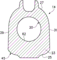
In the tooth of bagger, abrasive element 14 is the tips with homework department 21 and installation portion 23, and homework department 21 is forms of elongated very thin blade, and installation portion 23 limits and receives nose 18 jack 20 (Fig. 1-10).Most advanced and sophisticated 14 rotate through cutterhead, make it all engage with the soil in an identical manner basically all over excavating for every.As a result, most advanced and sophisticated 14 comprise front side 25 and rear side 27.Along with each rotation of cutterhead, front side 25 is at first to engage and guide a side that penetrates the soil with the soil.In the present invention, through blade 21 (Fig. 5) and at least in part through installation portion 23 (Fig. 4), rear side 27 has the width littler than front side 25 (that is, along the plane perpendicular to most advanced and sophisticated 14 longitudinal axis 28).In a preferred embodiment, run through most advanced and sophisticated 14 length, rear side 27 has the width (Fig. 4,5 and 7) littler than front side 25.
Most advanced and sophisticated 14 blade 21 preferably has roughly trapezoidal transverse configuration, and wherein, front side 25 is than rear side 27 wide (Fig. 5).Term " transverse configuration " is used in reference to along the two-dimensional structure perpendicular to the plane of the longitudinal axis 28 of abrasive element 14.Because most advanced and sophisticated narrows down, sidewall 29,31 is followed the shadow of front side 25 when excavating, thereby when digging operation, produces resistance hardly.In preferred structure, sidewall 29,31 is assembled (Fig. 5) with the angle θ of about 16 degree towards rear side 27; Yet the structure of other angle also is fine.Front side 25, rear side 27 and sidewall 29,31 can be the plane, curved surface or irregular.In addition, can adopt the shape except trapezoidal that front clearance (side relief) is provided.
In use, all over excavating (that is, along with each rotation of cutterhead), bagger most advanced and sophisticated 14 penetrates certain depth with the soil along with every.During most of useful life at tip, blade penetrates the soil alone.As an example, a soil height that excavates in the circulation roughly extends all over the central point that excavates every along line 3-3 (Fig. 2).Because only blade penetrates the soil and blade is thinner relatively, so the resistance during dredge operation is in the controlled range.Yet, along with being driven with fast speeds consistently, many teeth pass the soil, and power demand is always higher, and, when digging rock, also be useful to operation particularly even in blade, reduce resistance.
In preferable configuration, sidewall 29,31 is not only assembled towards rear side 27, and is configured such that sidewall is arranged in the shadow of the front side 25 of excavating profile." excavation profile " is used in reference to the cross-sectional configuration of the part at the tip 14 that penetrates the soil along a plane, and wherein said plane (i) whenever is parallel to direction of advance 34 and (ii) laterally perpendicular to longitudinal axis all over the central point that excavates what pass the soil.Compare with real cross section, excavating profile is to being applied to the better expression of the resistance on the tip between the operating period.In excavating profile, provide front clearance to depend on angle and axial slope or the expansion of tip end surface on backward directions that sidewall is assembled towards rear side.Aim to provide such width, when considering to excavate the phantom drawing of profile, this width the past side direction rear side basically narrows down.The cutterhead that front clearance in the excavation profile preferably extends through expectation excavates the angle, if but at least one excavation angle, there is such front clearance, still can obtain advantage.As just an example, the cross-sectional configuration shown in Fig. 3 representes to be driven an excavation profile 35 of the part at the tip 14 of passing the soil.As what can find out, along with sidewall 29,31 is assembled reducing resistance towards rear side 27, blade 21 even in excavating profile, still have front clearance.
Along with blade 21 wearing and tearing, the soil height spreads gradually backward, thereby the thicker part after each excavates in the circulation most advanced and sophisticated 14 more lean on is pushed through the soil.Therefore, along with points wear, need more power to drive cutterhead.Finally, enough blades are worn, and make to be driven through the soil at every installation portion 23 all over tip 14 in excavating.In the present invention, installation portion 23 at least the front end 40 (Fig. 4) of installation portion and preferably in whole erection portion (Fig. 4 and 7) comprise front clearance continuously.As shown in Figure 4, installation portion 23 is bigger than blade 21, be suitable for nose 18 receive in the jack 20 and be provided for most advanced and sophisticated 14 and base portion 12 between interconnective sufficient intensity.Sidewall 29,31 tilts, to assemble to rear side 27. Sidewall 29,31 is the angle [alpha] (Fig. 4) of about 26 degree in this example along the gradient of line 4-4, but the inclination angle that also can adopt other.As discussed above, the front clearance that excavates the profile desired depends on the relation between the axial expansion at sidewall lateral inclination and tip.
In the most advanced and sophisticated 14a of a routine, blade 21a has trapezoidal transverse configuration, has the front side 25a wideer than rear side 27a.Yet blade 21a does not provide front clearance in excavating profile.As what in Fig. 3 A, found out, the excavation profile 35a among Fig. 2 A (that is, along line 3A-3A) does not have sidewall 29a, the 31a (Fig. 2 A and 3A) that assembles towards rear side 27a.But along with sidewall extends towards rear side, the sidewall 29a, the 31a that excavate among the profile 35a outwards expand with the gradient that increases gradually.Opening backward of sidewall 29a, 31a will produce the resistance that increases on cutterhead.Compare with just in transverse configuration, adopting known sidewall, in the tip 14 of excavating profile, effectively adopt front clearance, reduced resistance better.
In another example, blade 21 has been worn down to the part along line 6-6 (Fig. 2 and 6) of installation portion 23 is passed the soil by driving degree.Even installation portion 23 is provided for reducing the front clearance of resistance; That is sidewall 29,31 even in excavating profile 45, assemble, towards rear side.Exist front clearance to make resistance littler in the excavation profile 45, thereby it is littler that the required power in soil is passed in its driving.Conversely, the resistance that reduces can make cutterhead continue to carry out operation with wearing up to the tip that installation portion penetrates the degree in soil.In the most advanced and sophisticated 14a of routine, installation portion 23a does not have band towards the sidewall 29a of rear side 27a convergence, the trapezoidal transverse configuration of 31a.And as what in Fig. 6 A, find out, 25a divides and opens from the front side in the excavation profile 45a that cuts open along the line 6a-6a around the front end 40a of installation portion 23a for sidewall 29a, 31a.Particularly compare, lack front clearance in the excavation profile and when most advanced and sophisticated 14a is driven through the soil, on most advanced and sophisticated 14a, apply very big resistance with of the present invention most advanced and sophisticated 14.Because the very big resistance that most advanced and sophisticated in the case 14a produces, many operators can (even not wearing and tearing fully of blade 21a) change most advanced and sophisticated when installation portion 23a begins to be driven through the soil.By the present invention, most advanced and sophisticated 14 can continue on base portion 12, further to be worn and torn until blade 21.
In preferred structure, the front end 37 of sidewall 29,31 from most advanced and sophisticated 14 47 continues to come to a point gradually to the rear end.As shown in Figure 7, even at the rear portion of installation portion 23, sidewall 29,31 is also assembled towards rear side 27.In addition, even in the excavation profile 55 of line 8-8 (Fig. 2 and 8), front clearance is being provided also, that is, even sidewall 29,31 is also assembled towards rear side 27 in the excavation profile 55 of this back.
As stated, in blade 21 and installation portion 23, use tip 14, in fact can use with socket configuration with any nose with front clearance.Yet in a preferable configuration, nose 18 front end 58 comprises towards preceding bearing surface 60, should be towards preceding bearing surface 60 around two vertical axises protrusions and crooked (Fig. 1,9 and 11-14).Similarly, the front end 62 of jack 20 is formed with complementary recessed and crooked bearing surface 64, against bearing surface 60 (Fig. 1,7,9 and 11) to be set.Shown in structure in, preceding bearing surface 60,64 is all consistent with spherical segment, is created in the stress in the parts to reduce because of the applying of non axial load (for example at US patent No.6, disclosed in 729,052, the full content of this patent is hereby incorporated by).
Preferably, front end 58,62 is roughly hemispherical, with reduce most advanced and sophisticated 14 and base portion 12 between quack sound, and more effectively resist load from all directions.The preceding bearing surface 64 of jack 20 is preferably slightly wide than the hemispherical of its end and center; Thereby be suitable for reliably being installed on the different base portions (promptly with most advanced and sophisticated 14; Need not binding perhaps reduces as far as possible), said base portion is being operated as real hemispherical socket surfaces on the hemispherical ball surface at base portion 12 under general load or the wearing and tearing subsequently.In the tooth 10a of routine (Fig. 2 A), along with tooth is forced through the soil, most advanced and sophisticated 14a moves on nose.Jack and nose 's front end is angled with respect to flat area supported and hard turning.In use, most advanced and sophisticated 14a moves on nose, makes the front portion of jack 20a around nose front end and against nose front end, send quack sound, and the jack rear end is moved around nose rear end and sent quack sound against nose rear end.Thisly move and send quack sound and make and most advanced and sophisticatedly wear and tear with base portion.In the present invention, use roughly hemispheric before bearing surface 60,64 reduced the quack sound (Fig. 1 and 9) at nose 18 and jack 20 front end places to a great extent.Yet, use level and smooth continuous preceding bearing surface can make the tip locate to roll to reduce wearing and tearing at nose.The little tape 65 that is arranged essentially parallel to longitudinal axis 28 preferably directly extends at the rear of hemispheric area supported roughly, thereby is still keeping the ability of the support of expectation when being provided at wearing and tearing for nose.Term " substantially parallel " be intended to comprise parallel surface with those from make or other purpose with low-angle (for example, about 1-7 degree) from surface that axis 28 axially departs from backward.Little tape 65 preferably is not more than 5 degree with respect to axis 28 axioversions, most preferably, and the about 2-3 degree of axioversion.
Be included in the main body 66 (Figure 11-14) at front end 58 rears for nose 18.Main body 66 is limited upper surface 68, soffit 69 and side surface 70,71.In preferred structure, body surfaces 68-71 disperses backward, makes nose 18 outwards to expand from front end 58, thereby nose the firmer harsh conditions that stand to excavate are provided.Yet, can only make upper and lower surperficial 68,69 to disperse each other, and side surface 70,71 is extended axially basically in parallel with each other.Jack 20 has the rear that is positioned at front end 62 to receive the major part 76 of main body 66.This major part 76 comprises the upper wall consistent with body surfaces 68-71 78, lower wall 79 and sidewall 80,81.In a preferred embodiment, main body 66 all has trapezoidal transverse configuration with major part 76.Employing is mainly along trapezoidal provide four turnings 67,77 of jack 20 with nose 18 length, and rotate to stop abrasive element 14 to center on axis 28 as isolated ridge at these four turnings 67,77.
In addition, in a preferred embodiment, among body surfaces 68-71 and the Socket walls 78-81 one of at least (and being preferably all these) have and bend to arc structure (Fig. 7,11 and 13) each other; That is, body surfaces 68-71 is preferably being recessed and crooked basically on whole width across it, to limit groove 84 on each side in four sides of main body 66.Similarly, Socket walls 78-81 is be preferably protrusion and crooked basically on the whole width across it, to limit the protuberance 86 that is received in the groove 84.Nose surperficial 68-71 and Socket walls 78-81 are preferably bending to arcly basically on the whole width across it, strengthened turning 67,77, in operation, most advanced and sophisticated 14 rotations around base portion 12 are provided the resistance of increase.Groove and protuberance also can reduce most advanced and sophisticated rotation quack sound on base portion.Though arcuate surfaces 68-71 and wall 78-81 are preferred, also can adopt other groove and protuberance to construct, for example quote US patent application No.11/706 as a reference here, disclosed in 582.Also can adopt other rotation stopping structure.
The use of groove 84 and protuberance 86, the particularly crooked gradually groove 84 and protuberance 86 that also extends through the whole width of surperficial 68-71 and wall 78-81 basically makes most advanced and sophisticated 14 to be assembled into easily on nose 18; That is the correct assembling position on, groove 84 imports nose 18 with most advanced and sophisticated 14 with protuberance 86 synergistically when assembling.For example; Tip 14 is being installed to a nose last time; If not correctly align with nose at first and are installed on nose 18 in tip 14, then supplied to backward on nose 18 along with the tip, received protuberance 86 joins to and will make the tip be rotated into correct alignment in the groove 84.The synergy of this groove 84 and protuberance 86 is simplified greatly and has been accelerated turning 67 and installed and be set in the turning 77.Between jack and nose 's shape, also can adopt some modification, as long as on the jack main body with nose form fit.
Nose surperficial 68-71 with groove 84 be axioversion preferably all, thus the outwards expansion along with extending back, to give nose 18 intensity is provided, up to the back surface of stability 85 that arrives nose 18.Likewise, the Socket walls 78-81 that has protuberance 86 also all expands with consistent with surperficial 68-71.Socket walls 78-81 also limits the back surface of stability 95, with the breasting surface of stability 85.The back surface of stability 85,95 is parallel with longitudinal axis 28 basically.In a preferred embodiment, each surface of stability 85,95 is axially to disperse with respect to the angle of axis 28 about 7 degree backward.The back surface of stability 85,95 also preferably surrounds (or surrounding at least basically) nose 18 and jack 20, to resist non axial load better.Though contacting between various socket surfaces during the digging operation are with nose may occur; But area supported 60,64 is intended to primarily stop be applied to the load on the tooth with the back surface of stability 85, contacting between 95 before corresponding, thereby desirable stability is provided.Though the surface of stability 85,95 preferably is formed with the short portion that extends axially, they can have longer or different structures.In addition, in some cases, for example, in tight duty operations, can under the condition that need not the surface of stability 85,95, obtain benefit.
The preceding bearing surface 60,64 and the back surface of stability 85,95 are arranged to make tip stabilizes on nose, and alleviate the stress in the parts.The jack 20 and the roughly hemispherical supporting surface 60,64 at nose 18 front end 58,62 places can stably resist with load (with their orientation independent that applies) diametical axially with non axial power backward.Adopt crooked continuously before area supported reduced most advanced and sophisticated quack sound and the stress that has when having reduced to have the turning on nose and concentrated.As quote US patent No.5 as a reference here, and 709,043 is disclosed, and the quack sound through reducing most advanced and sophisticated rear portion also provides the stable opposing to most advanced and sophisticated rear portion, the back surface of stability 85,95 and 60,64 complementations of preceding bearing surface.Around nose 18 whole girth or extend (Fig. 7,9 and 11-14) around whole girth at least basically, they also can resist the load of the non axial orientation that applies along any direction by the surface of stability 85,95.
The major part 76 of jack 20 preferably has nose 18 (Fig. 7 and 11) that roughly trapezoidal transverse configuration receives matched shape.The roughly trapezoidal transverse configuration of jack 20 is generally followed the roughly trapezoidal transverse configuration of the outside 97 at tip 14.The collaborative setting of jack 20 and outside 97 makes nose 18 the sizes maximization that can be accommodated in most advanced and sophisticated 14, and makes tip 14 be easy in casting process, create, and has improved strength-weight ratio.
Can use the different lock of many types that abrasive element 14 is fixed to base portion 12 releasedly.Yet in a preferred embodiment, in lock 16 openings 101 that are received in the abrasive element 14, opening 101 preferably is formed in the rear wall 27, though it also can be formed on other place (Fig. 1,9 and 15-20).Opening 101 preferably has axially elongated shape, and comprises antetheca 103, rear wall 105 and sidewall 107,109.Wheel rim 111 is structured in around the opening 101, with protection lock and extra intensity is provided.Wheel rim 111 also enlarges along rear wall 105, thereby extends to outside the outer surface 97 fartherly, and confirms to be used to hole 113 that lock 16 is passed through.This hole makes the position stability of lock 16, and allows the operator approaching easily.
Comprise for nose 18 from the outwards outstanding retainer 115 of nose 18 upside 68 to engage with lock 16.Retainer 115 preferably has the back side 119, and this back side 119 has recessed bent recess 121, and the front end 123 of lock 16 in use is received and remains in this depression 121, but also can adopt other layout and lock cooperation.In preferred structure, opening 101 long enoughs and rear wall 27 enough tilt, and are provided for the gap of retainer 115 thereby be installed to nose 18 last time at abrasive element 14.Yet, if desired, can in jack 20, be provided with relief or other form the gap so that retainer 115 pass through.In addition, preferably, limit the protuberance of retainer 115 through providing depression 118 to hold the part of lock 16.
Lock 16 is linear lock, is orientated roughly axially, so that abrasive element 14 is remained on the base portion 12, and carries out fastening to abrasive element 14 to the installation on nose 18.The linear lock of employing axial orientation has increased lock abrasive element has been installed in the fastening ability on nose; That is, it provides the more length of tightening up.In a preferred embodiment, lock 16 comprises and has front end 123 and the thread spindle 130 of the rear end 134 that has head, the nut 136 that is threaded into axle 130 and spring 138 (Fig. 1,9 and 15-20).Spring 138 is preferably formed by a series of resilient discs 140, and dish 140 is made up of foam, rubber or other elastomeric material, and is separated by liner 142, and liner 142 is the form of packing ring preferably.A plurality of dishes 140 are used to power, the elasticity that provides enough and tighten up.Packing ring is isolated resilient disc, makes them operate as a series of single spring elements.Packing ring 142 preferably is made up of plastics, but also can be processed by other material.In addition, the spring of preferable configuration is economical for making and being assembled on the axle 130.Yet, can adopt the spring of other kind.The end that thrust washer 142a or other device preferably are arranged on spring is to provide enough supports.
Axle 130 centers extend through spring 138 with coupling nut 136.The front end 123 of axle 130 is installed in the depression 121, makes axle 130 be arranged to against retainer 115 to support.Lock 16 rear end 134 extends through the hole 113 in the abrasive element 14, with can make the user in the outside of opening 101 near lock.Axle preferably is set at respect to axis 28 at angle, and feasible 134 approaching more easily.Spring 138 is arranged between rear wall 105 and the nut 136, makes it during lock is fastened, can apply bias force to abrasive element.Hole 113 is preferably big than 134, passes through during being installed to assembly 10 will locking 16 to allow it.Hole 113 also can form open slot, to be suitable for that axle 130 is inserted from the top simply.Also can adopt 134 shown in replacing of other tool engagement structure.
In the use, abrasive element 14 slides on nose 18, makes to be installed to (Fig. 1 and 9) in the jack 20 for nose 18.Lock can be through being positioned at opening 101 outsides and (for example being installed in axle 130 discharged retainer on every side; Simply reverse band) temporarily remain on and be used for the hole 113 of transporting, storing and/or installing, perhaps it can be installed after abrasive element is installed on nose.Under any circumstance, axle 130 is inserted via hole 113, and its front end 123 is arranged in the depression 121 of retainer 115.Lock 16 is positioned to along nose 18 outside, make need not in nose, to form the hole, slit waits and holds lock, thereby opposing load.134 by tool engagement and rotate, and so that locking is affixed to compressive state, thereby keeps abrasive element; That is, axle 130 rotates with respect to nut 136, makes front end 123 be pressed against on the retainer 115.This motion pulls nut 136 with against spring 138 again conversely backward, and this spring 138 is compressed between nut 136 and the rear wall 105.The fastening of lock 16 moved abrasive element 14 on nose 18 (that is, preceding bearing surface 60,64 engages) tightly, thereby is slidingly matched during use, and wearing and tearing are littler.Spring 138 is further compressed in the lasting rotation of axle 130.Then, begin wearing and tearing along with nose with jack, compressed spring 138 forces abrasive element 14 backward.Preferred nose 18 stability with most advanced and sophisticated 14 makes it possible to use axial lock, that is, do not have very big bending force to be applied to and lock, thereby can utilize the high axial compression strength of bolt, and abrasive element is remained to base portion.Lock 16 in light weight, no strikers, make easily, do not take a lot of spaces and need not and in nose, have any opening.
In preferred structure, lock 16 also comprises together with nut 136 and is installed to the indication portion 146 (Figure 15-20) on the axle 130.The plate that indication portion 146 is preferably processed by steel or other rigid material has and installs near the sidewall of opening 101 107,109 but be not the lateral edges 148,149 that is installed to tightly in the opening 101.Indication portion 146 comprises fully or receives partly the opening of nut 136, rotates when axle 130 rotates to prevent nut.Lateral edges 148,149 has prevented that to the tight reception of sidewall 107,109 indication portion 146 from rotating.Perhaps, indication portion can have the screwed hole as nut; If save indication portion, then need other device to come retention nut 136 not rotate.Indication portion 146 can be discontinuous with nut 136 also.
When suitably fastening indication portion 146 provide about the axle 130 visual indication with pressure from expectation to abrasive element that apply, thereby can on axle 130 and/or spring 138, not apply excessive stress.In preferred structure, indication portion 146 with along opening 101, labeling section 152 cooperations that promptly form along wheel rim 111 and/or sidewall 107,109.Labeling section 152 preferably one of in the sidewall 107,109 or both be positioned on the wheel rim 111, but also can have other structure.Labeling section 146 is ridge or some structures preferably, and are not only mark, thus its can wearing and tearing begin to occur with initial be used to make when fastening lock 16 fastening again.
When axle 130 rotates and nut 136 is pulled rearward when dragging, indication portion 146 is arranged in move backward under the condition of opening 101 (from the position of Figure 16) at nut 136.When indication portion 146 aligns with labeling section 152 (Figure 15), the operator knows fastening can stopping.In this position, regardless of nose go up and/or jack 20 in wearing and tearing, lock 16 applies predetermined pressure on abrasive element 14.Therefore, can easily avoid the fastening deficiency and the excessive tightness of locking.As selection, indication portion 146 can save, and axle 130 is fastened to the moment of torsion of scheduled volume.
Various aspects of the present invention preferably adopt together, to obtain optimum performance and advantage.Yet different aspects can adopt individually, with the benefit that provides them to be provided separately.