CN102704882A - Hydraulic forced centralizer - Google Patents
Hydraulic forced centralizer Download PDFInfo
- Publication number
- CN102704882A CN102704882A CN2012101435251A CN201210143525A CN102704882A CN 102704882 A CN102704882 A CN 102704882A CN 2012101435251 A CN2012101435251 A CN 2012101435251A CN 201210143525 A CN201210143525 A CN 201210143525A CN 102704882 A CN102704882 A CN 102704882A
- Authority
- CN
- China
- Prior art keywords
- piston
- centralizer
- casing
- cavity
- holes
- Prior art date
- Legal status (The legal status is an assumption and is not a legal conclusion. Google has not performed a legal analysis and makes no representation as to the accuracy of the status listed.)
- Pending
Links
Images

Landscapes
- Earth Drilling (AREA)
Abstract
一种液压强制扶正器。该液压强制扶正器包括上接头(5),所述的上接头(5)连接有本体(1),所述的本体(1)腔内设有活塞(4),活塞(4)腔内设有弹簧(3),活塞(4)对应的本体(1)壁上沿周向上分布有至少2排通孔,通孔内安装有钢球(2)。该扶正器迫使磨铣钻柱不随断口上部套管弯曲而变向,避免套管开窗,偏出管外。
A hydraulic forced centralizer. The hydraulic forced centralizer includes an upper joint (5), the upper joint (5) is connected with a body (1), the cavity of the body (1) is provided with a piston (4), and the cavity of the piston (4) is provided with a There is a spring (3), and at least 2 rows of through holes are distributed along the circumferential direction on the wall of the body (1) corresponding to the piston (4), and steel balls (2) are installed in the through holes. The centralizer forces the milling drill string not to change direction with the casing bending at the upper part of the fracture, preventing the casing from opening a window and deflecting out of the pipe.
Description
技术领域 technical field
本发明属于在油田大修井作业中一种工具,特别是一种液压强制扶正器。 The invention belongs to a tool used in major workover operations in oil fields, in particular to a hydraulic forced centralizer.
背景技术 Background technique
目前随着油田进一步的开发,井套损情况也越加复杂,尤其是小通径错断井,其上断口普遍存在变形,下断口又往往远离套管中心线,应用磨铣打通道时,磨铣工具易随断口上部套管弯曲而变向,导致磨出管外,导致通道丢失,致使小通径错断井修复率极低。 At present, with the further development of the oilfield, the well casing damage is becoming more and more complicated, especially in small-diameter staggered wells, where the upper fracture is generally deformed, and the lower fracture is often far away from the casing centerline. When using grinding and milling to drill channels, The grinding and milling tools are easy to change direction with the bending of the upper part of the fractured casing, resulting in grinding out of the casing and loss of channels, resulting in a very low repair rate for small-diameter faulted wells.
发明内容 Contents of the invention
为了解决背景技术中存在的问题,本发明提供一种液压强制扶正器,该扶正器迫使磨铣工具不随断口上部套管弯曲而变向,保证打通道顺利进行。 In order to solve the problems in the background technology, the present invention provides a hydraulic forced centralizer, which forces the milling tool not to change direction with the bending of the upper casing of the fracture, so as to ensure the smooth progress of tunneling.
本发明的技术方案是:该液压强制扶正器包括上接头,所述的上接头连接有本体,所述的本体腔内设有活塞,活塞腔内设有弹簧,活塞对应的本体壁上沿周向上均匀分布有至少2排通孔,通孔内安装有钢球。 The technical solution of the present invention is: the hydraulic forced centralizer includes an upper joint, the upper joint is connected with a body, the body cavity is provided with a piston, the piston cavity is provided with a spring, and the body wall corresponding to the piston is provided along the circumference There are at least 2 rows of through holes evenly distributed upwards, and steel balls are installed in the through holes.
本发明具有如下有益效果:本工具主要由滚珠、弹簧、活塞和本体组成。长度500mm,下井外径φ114mm,工作外径φ124mm,对磨铣工具及管柱达到强制扶正的目的。可多级使用。该扶正器迫使磨铣钻柱不随断口上部套管弯曲而变向,避免套管开窗,偏出管外。 The invention has the following beneficial effects: the tool is mainly composed of a ball, a spring, a piston and a body. The length is 500mm, the outer diameter of going down the well is φ114mm, and the outer diameter of working is φ124mm, which can achieve the purpose of forced straightening of milling tools and pipe strings. Can be used in multiple levels. The centralizer forces the milling drill string not to change direction with the casing bending at the upper part of the fracture, preventing the casing from opening a window and deflecting out of the pipe.
附图说明:Description of drawings:
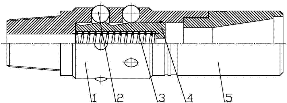
附图1是本发明的结构示意图。 Accompanying drawing 1 is a structural representation of the present invention.
图中1-本体; 2-钢球;3-弹簧;4-活塞;5-上接头。 In the figure 1-body; 2-steel ball; 3-spring; 4-piston; 5-upper joint.
具体实施方式:Detailed ways:
下面结合附图对本发明作进一步说明: The present invention will be further described below in conjunction with accompanying drawing:
如图1所示,该液压强制扶正器包括上接头5,所述的上接头5螺纹连接有本体1,所述的本体1腔内设有活塞4,活塞4腔内设有弹簧3,活塞4对应的本体1壁上沿周向上均匀分布有2排通孔,通孔内安装有钢球2。在液压的作用下,活塞4下移,弹簧3被压缩,钢球2从通孔内被挤出,钢球2贴在套管内壁上,对磨铣工具起到强制扶正的作用,迫使磨铣工具不随断口上部套管弯曲而变向,保证打通道顺利进行。磨铣结束液压消失,活塞4在弹簧3作用下回位,钢球2回到本体1内起出工具。 As shown in Figure 1, the hydraulic forced centralizer includes an upper joint 5, the upper joint 5 is threadedly connected with a body 1, a piston 4 is arranged in the cavity of the body 1, a spring 3 is arranged in the cavity of the piston 4, the piston 4 Correspondingly, two rows of through holes are evenly distributed along the circumference on the wall of the body 1, and steel balls 2 are installed in the through holes. Under the action of hydraulic pressure, the piston 4 moves down, the spring 3 is compressed, the steel ball 2 is extruded from the through hole, and the steel ball 2 sticks to the inner wall of the casing, which plays a role in forcing the milling tool to be corrected, forcing the milling tool to The milling tool does not change direction with the bending of the upper casing of the fracture, ensuring the smooth progress of channel drilling. After milling, the hydraulic pressure disappears, the piston 4 returns under the action of the spring 3, and the steel ball 2 returns to the body 1 to take out the tool.
Claims (1)
Priority Applications (1)
| Application Number | Priority Date | Filing Date | Title |
|---|---|---|---|
| CN2012101435251A CN102704882A (en) | 2012-05-09 | 2012-05-09 | Hydraulic forced centralizer |
Applications Claiming Priority (1)
| Application Number | Priority Date | Filing Date | Title |
|---|---|---|---|
| CN2012101435251A CN102704882A (en) | 2012-05-09 | 2012-05-09 | Hydraulic forced centralizer |
Publications (1)
| Publication Number | Publication Date |
|---|---|
| CN102704882A true CN102704882A (en) | 2012-10-03 |
Family
ID=46897909
Family Applications (1)
| Application Number | Title | Priority Date | Filing Date |
|---|---|---|---|
| CN2012101435251A Pending CN102704882A (en) | 2012-05-09 | 2012-05-09 | Hydraulic forced centralizer |
Country Status (1)
| Country | Link |
|---|---|
| CN (1) | CN102704882A (en) |
Cited By (3)
| Publication number | Priority date | Publication date | Assignee | Title |
|---|---|---|---|---|
| CN107780861A (en) * | 2017-09-27 | 2018-03-09 | 海林新科石油耐磨工具有限责任公司 | Casing damaged well diameter enlarging instrument |
| CN111894484A (en) * | 2020-08-11 | 2020-11-06 | 中国石油天然气集团有限公司 | A kind of hydraulic ball centralizer and using method |
| CN114278236A (en) * | 2021-12-24 | 2022-04-05 | 通化红光石油机械有限责任公司 | Casing centralizing and patching device |
Citations (6)
| Publication number | Priority date | Publication date | Assignee | Title |
|---|---|---|---|---|
| GB2352747A (en) * | 1999-07-27 | 2001-02-07 | Baker Hughes Inc | Reusable cutting and milling tool |
| US20020144815A1 (en) * | 2001-03-10 | 2002-10-10 | Van Drentham-Susman Hector F.A. | Guide apparatus |
| US7240744B1 (en) * | 2006-06-28 | 2007-07-10 | Jerome Kemick | Rotary and mud-powered percussive drill bit assembly and method |
| CN200946464Y (en) * | 2006-09-08 | 2007-09-12 | 大庆油田有限责任公司 | Rigid centralizer for straight well and directional well |
| CN201071687Y (en) * | 2007-08-04 | 2008-06-11 | 孙志健 | Hydraulic reducing centralizer |
| CN201306132Y (en) * | 2008-12-02 | 2009-09-09 | 赵勇 | Tripping and eccentric wear preventing centralizer of oil well pump |
-
2012
- 2012-05-09 CN CN2012101435251A patent/CN102704882A/en active Pending
Patent Citations (6)
| Publication number | Priority date | Publication date | Assignee | Title |
|---|---|---|---|---|
| GB2352747A (en) * | 1999-07-27 | 2001-02-07 | Baker Hughes Inc | Reusable cutting and milling tool |
| US20020144815A1 (en) * | 2001-03-10 | 2002-10-10 | Van Drentham-Susman Hector F.A. | Guide apparatus |
| US7240744B1 (en) * | 2006-06-28 | 2007-07-10 | Jerome Kemick | Rotary and mud-powered percussive drill bit assembly and method |
| CN200946464Y (en) * | 2006-09-08 | 2007-09-12 | 大庆油田有限责任公司 | Rigid centralizer for straight well and directional well |
| CN201071687Y (en) * | 2007-08-04 | 2008-06-11 | 孙志健 | Hydraulic reducing centralizer |
| CN201306132Y (en) * | 2008-12-02 | 2009-09-09 | 赵勇 | Tripping and eccentric wear preventing centralizer of oil well pump |
Cited By (5)
| Publication number | Priority date | Publication date | Assignee | Title |
|---|---|---|---|---|
| CN107780861A (en) * | 2017-09-27 | 2018-03-09 | 海林新科石油耐磨工具有限责任公司 | Casing damaged well diameter enlarging instrument |
| CN111894484A (en) * | 2020-08-11 | 2020-11-06 | 中国石油天然气集团有限公司 | A kind of hydraulic ball centralizer and using method |
| CN111894484B (en) * | 2020-08-11 | 2025-02-28 | 中国石油天然气集团有限公司 | A hydraulic ball centralizer and use method |
| CN114278236A (en) * | 2021-12-24 | 2022-04-05 | 通化红光石油机械有限责任公司 | Casing centralizing and patching device |
| CN114278236B (en) * | 2021-12-24 | 2024-05-28 | 通化红光石油机械有限责任公司 | A casing straightening and patching device |
Similar Documents
| Publication | Publication Date | Title |
|---|---|---|
| CN104314482B (en) | Closed type helical hole-protecting drill and using method thereof for drilling of soft coal bed | |
| CN201031634Y (en) | Radial variable casing tube centralizer | |
| WO2011031480A3 (en) | Method and apparatus for controlling bottomhole temperature in deviated wells | |
| CN107143284A (en) | The application method of the method for coal mine long range throughbore draining, equipment and equipment | |
| CN102704882A (en) | Hydraulic forced centralizer | |
| CN204266948U (en) | Closed spiral guard aperture drilling tool is crept into for weak seam | |
| CN202531051U (en) | Hydraulic casing centralizer | |
| CN203081286U (en) | Anti-hole-collapse drilling tool | |
| CN202441260U (en) | Oil field coring bit | |
| CN101666211A (en) | Pneumatic impactor impacting inversely | |
| CN104295258A (en) | Novel drifting-wall scraping integrated operating gauge cutter and operating pipe column | |
| CN103643901A (en) | Reversing joint for oil field workover | |
| CN207776795U (en) | A kind of chambering device structure | |
| CN203756034U (en) | Hydraulic expansion drilling following hole opener | |
| CN102852504A (en) | Multi-layer fracturing tool string for vertical well without moving string | |
| CN203161090U (en) | Drill for oil exploration | |
| CN207598193U (en) | The used drilling rod well logging composite drill bit of total cost management | |
| CN203035125U (en) | Hollow drill rod for oil drilling | |
| CN203097716U (en) | Combined drill column device for drilling of directional well | |
| CN204677154U (en) | Novel pressure break Special packer | |
| CN203335019U (en) | Alloy steel head float shoe | |
| CN205259967U (en) | Coiled tubing protection device and use this protection device's many bunches of staged fracturing instruments | |
| CN204225818U (en) | Novel dredging, scraping wall one operation drift size gauge tool and working string | |
| CN202544787U (en) | Novel oil well casing shaper | |
| CN204941402U (en) | Grappling water booster system |
Legal Events
| Date | Code | Title | Description |
|---|---|---|---|
| C06 | Publication | ||
| PB01 | Publication | ||
| C10 | Entry into substantive examination | ||
| SE01 | Entry into force of request for substantive examination | ||
| C12 | Rejection of a patent application after its publication | ||
| RJ01 | Rejection of invention patent application after publication |
Application publication date: 20121003 |