CN102693770A - Coordinate ground vehicle system of nuclear power plant - Google Patents
Coordinate ground vehicle system of nuclear power plant Download PDFInfo
- Publication number
- CN102693770A CN102693770A CN2012101705462A CN201210170546A CN102693770A CN 102693770 A CN102693770 A CN 102693770A CN 2012101705462 A CN2012101705462 A CN 2012101705462A CN 201210170546 A CN201210170546 A CN 201210170546A CN 102693770 A CN102693770 A CN 102693770A
- Authority
- CN
- China
- Prior art keywords
- shielding
- movable device
- movable fixture
- fixed
- manhole cover
- Prior art date
- Legal status (The legal status is an assumption and is not a legal conclusion. Google has not performed a legal analysis and makes no representation as to the accuracy of the status listed.)
- Pending
Links
Images


Landscapes
- Monitoring And Testing Of Nuclear Reactors (AREA)
Abstract
本发明属于反应堆工程技术领域,公开了一种核电站坐标地车系统,包括:屏蔽罩、第一可移动装置和第二可移动装置;屏蔽罩固定在第一可移动装置上所开设的孔内,屏蔽罩的内腔设置有贮罐吊具;第一可移动装置包括第一车轮,第二可移动装置包括前后布置的多根梁以及安装在梁两端的第二车轮,多根梁上分别安装有第一轨道,第一可移动装置可通过第一车轮沿第一轨道左右运动;第二可移动装置下方设置有竖井,竖井的顶部为屏蔽楼板,屏蔽楼板上开有井口,井口内装有屏蔽井盖,屏蔽井盖上方设有井盖抓具。本发明能够实现高温堆乏燃料贮存竖井的精确定位和安全操作。
The invention belongs to the technical field of reactor engineering, and discloses a nuclear power plant coordinate ground vehicle system, comprising: a shielding cover, a first movable device and a second movable device; the shielding cover is fixed in a hole provided on the first movable device , the inner cavity of the shielding cover is provided with a storage tank hanger; the first movable device includes a first wheel, and the second movable device includes a plurality of beams arranged in front and rear and second wheels installed at both ends of the beam, and the plurality of beams are respectively The first track is installed, and the first movable device can move left and right along the first track through the first wheels; a shaft is arranged under the second movable device, and the top of the shaft is a shielding floor, and a wellhead is opened on the shielding floor, and a wellhead is installed in the wellhead. The shielded manhole cover is provided with a manhole cover gripper above the shielded manhole cover. The invention can realize the precise positioning and safe operation of the spent fuel storage shaft of the high temperature reactor.
Description
技术领域 technical field
本发明属于反应堆工程技术领域,特别是涉及一种核电站坐标地车系统。The invention belongs to the technical field of reactor engineering, in particular to a nuclear power plant coordinate ground vehicle system.
背景技术 Background technique
高温堆核电站被公认为是具有第四代核电主要特征的核电站,具有固有安全、防止核扩散、可产生高温工艺热等优点。The high-temperature reactor nuclear power plant is recognized as a nuclear power plant with the main characteristics of the fourth-generation nuclear power, which has the advantages of inherent safety, nuclear proliferation prevention, and high-temperature process heat generation.
球床高温气冷堆采用球形燃料元件,燃料元件内弥散有涂敷燃料颗粒。球形燃料元件是将一定数量的燃料颗粒和基体石墨充分混合,压成直径50mm的石墨球,然后再在外部包裹压制一层纯石墨作为燃料元件的外壳,压制好的燃料元件外径为60mm。球床高温气冷堆从堆芯排出的球形乏燃料,需要采用合适的贮存容器,并贮存在合适的中间贮存设施内,其中可行的一种贮存方案是将乏燃料贮罐放入屏蔽贮存竖井内贮存。乏燃料贮存竖井的顶部设有屏蔽井盖,屏蔽井盖可由钢制、灌铅或混凝土制成,其中混凝土屏蔽井盖的成本最低。在将乏燃料贮罐放入贮存竖井或将贮罐从竖井内取出时,首先需要将屏蔽井盖提起,然后进行贮罐在竖井内的吊装操作。在乏燃料贮罐和屏蔽井盖的操作过程中,需要通过一套可精确定位的地车系统,将贮罐和井盖吊具精确定位到各个贮存竖井上方,该地车系统要求在各种工况下,都能够保证贮罐和井盖吊装定位操作的安全可靠。The pebble bed high-temperature gas-cooled reactor adopts spherical fuel elements, and coated fuel particles are dispersed in the fuel elements. Spherical fuel element is to fully mix a certain amount of fuel particles and matrix graphite, press it into a graphite ball with a diameter of 50mm, and then wrap and press a layer of pure graphite on the outside as the shell of the fuel element. The outer diameter of the pressed fuel element is 60mm. The spherical spent fuel discharged from the core of the pebble bed high temperature gas-cooled reactor needs to be stored in a suitable storage container in a suitable intermediate storage facility. One of the feasible storage solutions is to put the spent fuel storage tank into the shielded storage shaft internal storage. The top of the spent fuel storage shaft is equipped with a shielded manhole cover, which can be made of steel, lead-filled or concrete, and the cost of the concrete shielded manhole cover is the lowest. When putting the spent fuel storage tank into the storage shaft or taking the storage tank out of the shaft, it is first necessary to lift the shielding manhole cover, and then carry out the hoisting operation of the storage tank in the shaft. During the operation of spent fuel storage tanks and shielded manhole covers, it is necessary to accurately position the storage tanks and manhole cover spreaders above each storage shaft through a set of ground truck system that can be accurately positioned. It can ensure the safe and reliable hoisting and positioning operation of storage tanks and manhole covers.
目前还没有一种能够实现高温堆乏燃料贮存竖井的精确定位和安全操作的设备。At present, there is no equipment that can realize the precise positioning and safe operation of the high temperature reactor spent fuel storage shaft.
发明内容 Contents of the invention
(一)要解决的技术问题(1) Technical problems to be solved
本发明要解决的技术问题是:如何实现高温堆乏燃料贮存竖井的精确定位和安全操作。The technical problem to be solved by the invention is: how to realize the precise positioning and safe operation of the high temperature reactor spent fuel storage shaft.
(二)技术方案(2) Technical solutions
为了解决上述技术问题,本发明提供一种核电站坐标地车系统,包括:屏蔽罩、第一可移动装置和第二可移动装置;In order to solve the above technical problems, the present invention provides a nuclear power plant coordinate ground vehicle system, including: a shield, a first movable device and a second movable device;
所述屏蔽罩固定在第一可移动装置上所开设的孔内,所述屏蔽罩的内腔设置有贮罐吊具;The shielding cover is fixed in the hole provided on the first movable device, and the inner cavity of the shielding cover is provided with a storage tank hanger;
所述第一可移动装置包括第一车轮,所述第二可移动装置包括前后布置的多根梁以及安装在所述梁两端的第二车轮,所述多根梁上分别安装有第一轨道,所述第一可移动装置可通过所述第一车轮沿第一轨道左右运动;The first movable device includes first wheels, the second movable device includes a plurality of beams arranged front and rear and second wheels installed at both ends of the beams, and first rails are respectively installed on the plurality of beams , the first movable device can move left and right along the first track through the first wheels;
所述第二可移动装置下方设置有竖井,所述竖井的顶部为屏蔽楼板,所述屏蔽楼板上开有井口,所述井口内装有屏蔽井盖,所述屏蔽井盖上方设有井盖抓具。A shaft is arranged below the second movable device, the top of the shaft is a shielding floor, and a wellhead is opened on the shielding floor, a shielding well cover is installed in the wellhead, and a well cover grab is arranged above the shielding well cover.
优选地,所述竖井由侧墙围成。Preferably, the shaft is enclosed by side walls.
优选地,屏蔽楼板上方的舱室两端安装有第二轨道,所述第二可移动装置可通过所述第二车轮沿第二轨道前后运动。Preferably, second rails are installed at both ends of the cabin above the shielding floor, and the second movable device can move back and forth along the second rails through the second wheels.
优选地,所述屏蔽罩的底部设有可拆卸的底板。Preferably, a detachable bottom plate is provided at the bottom of the shielding case.
优选地,所述第一可移动装置上固定有卷扬机,所述卷扬机的卷筒上缠绕有钢丝绳,所述钢丝绳的一端固定在所述卷扬机上,另一端固定在所述贮罐吊具上,中部通过设置在屏蔽罩顶盖上的滑轮进行导向。Preferably, a winch is fixed on the first movable device, a steel wire rope is wound on the reel of the winch, one end of the steel wire is fixed on the winch, and the other end is fixed on the storage tank spreader, The middle part is guided by pulleys arranged on the top cover of the shield.
优选地,所述屏蔽罩顶盖上开有多个开孔,所述钢丝绳穿过所述开孔与屏蔽罩内腔的贮罐吊具连接。Preferably, a plurality of openings are opened on the top cover of the shielding case, and the steel wire rope passes through the openings to be connected with the storage tank hanger in the inner cavity of the shielding case.
优选地,所述系统还包括电动机和减速机,所述电动机和减速机固定在第一可移动装置上,所述减速机的输入端连接电动机,输出端连接卷扬机。Preferably, the system further includes a motor and a reducer, the motor and the reducer are fixed on the first movable device, the input end of the reducer is connected to the motor, and the output end is connected to the hoist.
优选地,所述卷扬机、电动机和减速机各有两套。Preferably, there are two sets of winches, electric motors and reducers.
优选地,所述系统还包括电动葫芦和支架,所述电动葫芦固定在支架上,且通过链条与所述井盖抓具连接,所述支架固定在所述第一可移动装置上。Preferably, the system further includes an electric hoist and a bracket, the electric hoist is fixed on the bracket and connected to the manhole cover grab through a chain, and the bracket is fixed on the first movable device.
优选地,所述支架上固定有井盖导向条。Preferably, a manhole cover guide strip is fixed on the support.
(三)有益效果(3) Beneficial effects
上述技术方案具有如下优点:能够实现高温堆乏燃料贮存竖井的精确定位和安全操作:通过第一可移动装置的左右运动和第二可移动装置的前后运动,能够实现屏蔽罩和井盖抓具在各个井口上的精确定位;在支架上固定有井盖导向条,为屏蔽井盖的上下运动提供导向,从而保证了屏蔽井盖上下运动时不会晃动,定位准确;卷扬机、电动机和减速机各有两套,可以实现乏燃料贮罐吊装的冗余安全。The above technical solution has the following advantages: it can realize the precise positioning and safe operation of the high temperature reactor spent fuel storage shaft: through the left and right movement of the first movable device and the forward and backward movement of the second movable device, the shielding cover and the manhole cover grab can be realized Precise positioning on each wellhead; manhole cover guide strips are fixed on the bracket to provide guidance for the up and down movement of the shielded manhole cover, thus ensuring that the shielded manhole cover will not shake when moving up and down and the positioning is accurate; there are two sets of hoist, motor and reducer , can realize the redundant safety of hoisting spent fuel storage tank.
附图说明 Description of drawings
图1是本发明实施例的系统的部分结构的前视图;Fig. 1 is the front view of the partial structure of the system of the embodiment of the present invention;
图2是本发明实施例的系统的俯视图;Fig. 2 is the top view of the system of the embodiment of the present invention;
图3是本发明实施例的侧剖视图;Fig. 3 is a side sectional view of an embodiment of the present invention;
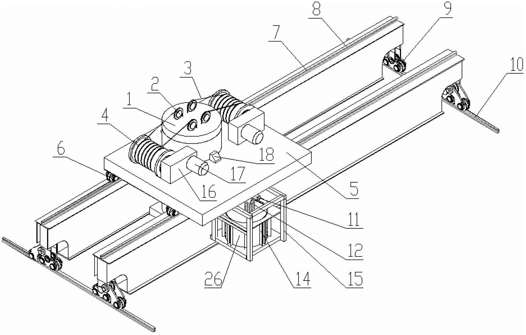
图4是本发明实施例的部分结构的轴测图。Fig. 4 is an axonometric view of a part of the structure of the embodiment of the present invention.
其中,1屏蔽罩;2滑轮;3钢丝绳;4卷扬机;5第一可移动装置;6第一车轮;7第二可移动装置;8第一轨道;9第二车轮;10第二轨道;11电动葫芦;12链条;13井盖抓具;14井盖导向条;15支架;16减速机;17电动机;18支承座;19井口;20竖井;21侧墙;22贮罐吊具;23乏燃料贮罐;24底板;25屏蔽楼板;26屏蔽井盖。Among them, 1 shielding cover; 2 pulley; 3 wire rope; 4 hoist; 5 first movable device; 6 first wheel; 7 second movable device; 8 first track; 9 second wheel; 10 second track; 11 Electric hoist; 12 chain; 13 manhole cover grab; 14 manhole cover guide bar; 15 support; 16 reducer; 17 motor; 18 support seat; 19 wellhead; 20 shaft; tank; 24 bottom plate; 25 shielded floor; 26 shielded manhole cover.
具体实施方式 Detailed ways
下面结合附图和实施例,对本发明的具体实施方式作进一步详细描述。以下实施例用于说明本发明,但不用来限制本发明的范围。The specific implementation manners of the present invention will be further described in detail below in conjunction with the accompanying drawings and embodiments. The following examples are used to illustrate the present invention, but are not intended to limit the scope of the present invention.
如图1~图4所示,本发明实施例的核电站坐标地车系统的结构如下:As shown in Figures 1 to 4, the structure of the nuclear power plant coordinate ground vehicle system in the embodiment of the present invention is as follows:
乏燃料的贮存竖井20由四周的侧墙21构成,竖井20的顶部为屏蔽楼板25,屏蔽楼板25上开有各竖井20的井口19,井口19内装有屏蔽井盖26。The spent
第二轨道10安装在屏蔽楼板25上方的舱室两端,第二可移动装置7由前后布置的两根梁构成,两根梁的两端安装有第二车轮9,第二可移动装置7可通过第二车轮9沿第二轨道10前后运动。The
第二可移动装置7的两根梁上分别安装有第一轨道8,第一可移动装置5可通过安装在其下方的第一车轮6沿第一轨道8左右运动。通过第二可移动装置7的前后运动和第一可移动装置5的左右运动,能够实现屏蔽罩1和井盖抓具13在各个井口19上的精确定位。第一可移动装置5除了包含第一车轮6还包含车体,所述车体在本实施例中由钢板制成。
第一可移动装置5的中间部位开有圆孔,屏蔽罩1通过支承座18固定在第一可移动装置5的圆孔内,屏蔽罩1的内腔可容纳一个乏燃料贮罐23,乏燃料贮罐23可放置在屏蔽罩1底部的可抽拉的底板24上,底板24可以打开,将乏燃料贮罐23吊入和吊出屏蔽罩1的内腔。The middle part of the first
屏蔽罩1的内腔设置有贮罐吊具22,用来吊装乏燃料贮罐23。用于驱动贮罐吊具22上升和下降的卷扬机4固定在第一可移动装置5上,卷扬机4的卷筒上缠绕钢丝绳3,钢丝绳3的一端固定在卷扬机4上,另外一端固定在贮罐吊具22上,中间通过固定在屏蔽罩1顶盖上的滑轮2导向,屏蔽罩1顶盖上开有多个开孔,钢丝绳3可穿过该开孔与屏蔽罩1内腔的贮罐吊具22连接。用于驱动卷扬机4转动的电动机17和减速机16也固定在第一可移动装置5上,减速机16的输入端连接电动机17,输出端连接卷扬机4。The inner cavity of the shielding cover 1 is provided with a
用于吊装贮罐吊具22的卷扬机4、电动机17和减速机16各有两套,可以实现乏燃料贮罐23吊装的冗余安全,在发生任何一套卷扬机组故障的意外工况下,仍然能够保证乏燃料贮罐吊装的安全性。There are two sets of
用于吊装屏蔽井盖26的是井盖抓具13,井盖抓具13可以抓取屏蔽井盖26或从屏蔽井盖26上脱开,用于驱动井盖抓具13上升和下降的是电动葫芦11,电动葫芦11固定在支架15上,支架15则固定在第一可移动装置5上,电动葫芦11通过链条12连接到井盖抓具13上。为了保证屏蔽井盖26上下运动的方向准确,在支架15上设置有圆周布置的井盖导向条14,井盖导向条14固定在支架15上,为屏蔽井盖26的上下运动提供导向。The
该核电站坐标地车系统的操作过程如下:The operation process of the coordinate ground vehicle system of the nuclear power plant is as follows:
1、将乏燃料贮罐23从屏蔽罩1内吊入竖井20:1. Hoist the spent
初始状态为:屏蔽罩1内已放入了一个乏燃料贮罐23,乏燃料贮罐23放置在抽拉底板24上。各竖井20的井口均装有屏蔽井盖26。The initial state is: a spent
操作过程为:The operation process is:
第二可移动装置7和第一可移动装置5带动屏蔽罩1,通过编码器或其他方式将井盖抓具13的中心精确定位到指定竖井20的井口19中心上,操作电动葫芦11将井盖抓具13下降至屏蔽井盖26的凹槽内,操作井盖抓具13抓住屏蔽井盖26,操作电动葫芦11将屏蔽井盖26从井口19内提起,在井盖导向条14的导向作用下,提至支架15内,完成屏蔽井盖26从井口19内提起的操作。The second
操作移动第二可移动装置7,通过编码器或其他方式将屏蔽罩1的中心精确定位到指定竖井20的井口19中心上,操作卷扬机4的电动机17,贮罐吊具22将乏燃料贮罐23从底板24上提起,然后操作将底板24打开,操作卷扬机4的电动机17,贮罐吊具22将乏燃料贮罐23从屏蔽罩1的内腔下放,通过井口19,将乏燃料贮罐23放至竖井20内存放,然后远程操作贮罐吊具22,使其从乏燃料贮罐23上脱开,操作卷扬机4的电动机17,将贮罐吊具22从竖井20收回到屏蔽罩1的内腔,操作将底板24关闭,完成乏燃料贮罐23从屏蔽罩1内吊入竖井20内进行贮存的操作。Operate and move the second
操作移动第二可移动装置7,通过编码器或其他方式将井盖抓具13的中心重新精确定位到指定竖井20的井口19中心上,操作电动葫芦11和井盖抓具13将屏蔽井盖26下放至竖井20的井口19内,操作井盖抓具13使其从屏蔽井盖26上脱开,操作电动葫芦11将井盖抓具13从屏蔽井盖26上提至支架15内,完成屏蔽井盖26放回至井口19的操作。Operate and move the second
2、将乏燃料贮罐23从竖井20吊入屏蔽罩1内:2. Hoist the spent
初始状态为:屏蔽罩1内没有放置乏燃料贮罐23,底板24处于关闭状态。各竖井20的井口均装有屏蔽井盖26。The initial state is: no spent
操作过程为:The operation process is:
第二可移动装置7和第一可移动装置5带动屏蔽罩1,通过编码器或其他方式将井盖抓具13的中心精确定位到指定竖井20的井口19中心上,操作电动葫芦11将井盖抓具13下降至屏蔽井盖26的凹槽内,操作井盖抓具13抓住屏蔽井盖26,操作电动葫芦11将屏蔽井盖26从井口19内提起,在井盖导向条14的导向作用下,提至支架15内,完成屏蔽井盖26从井口19内提起的操作。The second
操作移动第二可移动装置7,通过编码器或其他方式将屏蔽罩1的中心精确定位到指定竖井20的井口19中心上,操作将底板24打开,操作卷扬机4的电动机17,贮罐吊具22从屏蔽罩1的内腔下放,通过井口19,将贮罐吊具22下放至竖井20内存放的乏燃料贮罐23上,然后远程操作贮罐吊具22,使其抓住乏燃料贮罐23的吊装口,操作卷扬机4的电动机17,将贮罐吊具22和乏燃料贮罐23从竖井20收回到屏蔽罩1的内腔,操作将底板24关闭,然后操作卷扬机4的电动机17,将乏燃料贮罐23下放到底板24上,完成乏燃料贮罐23从竖井20吊入屏蔽罩1内腔存放的操作。Operate and move the second
操作移动第二可移动装置7,通过编码器或其他方式将井盖抓具13的中心重新精确定位到指定竖井20的井口19中心上,操作电动葫芦11和井盖抓具13将屏蔽井盖26下放至竖井20的井口19内,操作井盖抓具13使其从屏蔽井盖26上脱开,操作电动葫芦11将井盖抓具13从屏蔽井盖26上提至支架15内,完成屏蔽井盖26放回至井口19的操作。Operate and move the second
由以上实施例可以看出,本发明实施例提出的核电站坐标地车系统,具有以下优点:It can be seen from the above embodiments that the nuclear power plant coordinate ground vehicle system proposed by the embodiments of the present invention has the following advantages:
1.可以实现第二可移动装置7和第一可移动装置5的远距离遥控操作,避免操作人员近距离操作受到辐射;1. It can realize the long-distance remote control operation of the second
2.通过编码器的方式对第二可移动装置7和第一可移动装置5进行精确定位,可提高各项操作的可靠性;2. Precise positioning of the second
3.通过屏蔽罩对乏燃料贮罐进行辐射屏蔽,可允许操作人员近距离操作和维护,避免受到辐射;3. Radiation shielding of the spent fuel storage tank through the shielding cover allows operators to operate and maintain at close range to avoid radiation exposure;
4.用于吊装贮罐的卷扬机有两套,可以实现乏燃料贮罐吊装的冗余安全,在发生任何一套卷扬机组故障的意外工况下,仍然能够保证乏燃料贮罐吊装的安全性;4. There are two sets of winches for hoisting the storage tanks, which can realize the redundant safety of hoisting the spent fuel storage tanks, and can still ensure the safety of hoisting the spent fuel storage tanks in the event of accidental working conditions in which any set of hoisting units fails ;
5.可以实现屏蔽井盖吊装的远距离遥控操作,避免操作人员近距离操作受到辐射;5. It can realize the long-distance remote control operation of the hoisting of the shielded manhole cover, so as to avoid the radiation of the operator when operating at close range;
6.可以实现贮罐吊装的远距离遥控操作,避免操作人员近距离操作受到辐射;6. It can realize the long-distance remote control operation of storage tank hoisting, and avoid the operator from being exposed to radiation when operating at close range;
7.通过对地车、屏蔽罩、井盖吊具、贮罐吊具等设备的一体化设计,可以实现乏燃料贮罐贮存操作的各项功能,满足核电站的集成化要求。7. Through the integrated design of ground vehicles, shielding covers, manhole cover spreaders, storage tank spreaders and other equipment, various functions of spent fuel storage tank storage operations can be realized to meet the integration requirements of nuclear power plants.
本发明的系统能够实现高温堆乏燃料贮存竖井的精确定位和安全操作,该地车系统经过适当修改,可用来操作压水堆核电站和其它类型核电站的乏燃料贮罐、屏蔽井盖或其他设备,也可应用于普通工业各类工况下的精确定位和吊装操作。The system of the present invention can realize the precise positioning and safe operation of the spent fuel storage shaft of the high temperature reactor, and the truck system can be used to operate spent fuel storage tanks, shielded manhole covers or other equipment of pressurized water reactor nuclear power plants and other types of nuclear power plants after appropriate modification, It can also be applied to precise positioning and hoisting operations under various working conditions in general industries.
以上所述仅是本发明的优选实施方式,应当指出,对于本技术领域的普通技术人员来说,在不脱离本发明技术原理的前提下,还可以做出若干改进和替换,这些改进和替换也应视为本发明的保护范围。The above is only a preferred embodiment of the present invention, it should be pointed out that for those of ordinary skill in the art, without departing from the technical principle of the present invention, some improvements and replacements can also be made, these improvements and replacements It should also be regarded as the protection scope of the present invention.
Claims (10)
Priority Applications (1)
| Application Number | Priority Date | Filing Date | Title |
|---|---|---|---|
| CN2012101705462A CN102693770A (en) | 2012-05-28 | 2012-05-28 | Coordinate ground vehicle system of nuclear power plant |
Applications Claiming Priority (1)
| Application Number | Priority Date | Filing Date | Title |
|---|---|---|---|
| CN2012101705462A CN102693770A (en) | 2012-05-28 | 2012-05-28 | Coordinate ground vehicle system of nuclear power plant |
Publications (1)
| Publication Number | Publication Date |
|---|---|
| CN102693770A true CN102693770A (en) | 2012-09-26 |
Family
ID=46859146
Family Applications (1)
| Application Number | Title | Priority Date | Filing Date |
|---|---|---|---|
| CN2012101705462A Pending CN102693770A (en) | 2012-05-28 | 2012-05-28 | Coordinate ground vehicle system of nuclear power plant |
Country Status (1)
| Country | Link |
|---|---|
| CN (1) | CN102693770A (en) |
Cited By (10)
| Publication number | Priority date | Publication date | Assignee | Title |
|---|---|---|---|---|
| CN104485144A (en) * | 2014-12-08 | 2015-04-01 | 中广核工程有限公司 | Shielding device for transferring radioactive waste bins of nuclear power plants |
| CN107837465A (en) * | 2017-11-21 | 2018-03-27 | 西安大医数码科技有限公司 | One kind stem apparatus and system |
| WO2018191852A1 (en) * | 2017-04-17 | 2018-10-25 | 西安大医数码技术有限公司 | Source removing and introducing tooling, smart cart and source removing and introducing system |
| CN110415856A (en) * | 2019-07-09 | 2019-11-05 | 江苏中海华核环保有限公司 | A compacting machine that automatically detects the radiation dose on the surface of the barrel cake and optimizes the barrel cake |
| CN110544546A (en) * | 2018-07-18 | 2019-12-06 | 中国核电工程有限公司 | A transport system for storage |
| CN110642176A (en) * | 2019-10-22 | 2020-01-03 | 浙江工业大学 | Inspection shaft lid transport mechanism |
| CN112408207A (en) * | 2020-11-06 | 2021-02-26 | 莱德沃重工机械(上海)有限公司 | Loader, system and method for storing and taking radiation articles |
| CN112820430A (en) * | 2019-11-18 | 2021-05-18 | 中国核工业二三建设有限公司 | Method for installing and constructing high-temperature gas cooled reactor graphite and carbon reactor internal member and installing trolley |
| CN112951467A (en) * | 2021-01-29 | 2021-06-11 | 中国原子能科学研究院 | Filter core transfer device |
| CN116588787A (en) * | 2023-05-16 | 2023-08-15 | 中广核研究院有限公司 | A stack internal component hoisting system |
Citations (7)
| Publication number | Priority date | Publication date | Assignee | Title |
|---|---|---|---|---|
| CN2238182Y (en) * | 1995-05-29 | 1996-10-23 | 武汉列电实业公司 | Tripper for vehicle |
| JP3917998B2 (en) * | 2004-11-08 | 2007-05-23 | 三菱重工業株式会社 | Storage system, and storage container and container transport device used for storage system |
| CN201183713Y (en) * | 2008-04-03 | 2009-01-21 | 中国有色(沈阳)冶金机械有限公司 | The lifting guide device of the unloading pipe of the aluminum electrolysis multifunctional crane |
| CN101740147A (en) * | 2009-12-17 | 2010-06-16 | 清华大学 | Dry vertical shaft storage system for spent fuel of nuclear power station and storage method thereof |
| CN201534754U (en) * | 2009-06-03 | 2010-07-28 | 张智坤 | Numerical control crane used in radioactive storage depot |
| CN101916605A (en) * | 2010-07-26 | 2010-12-15 | 清华大学 | A complete set of equipment for shielding cover of nuclear power plant spent fuel storage tank |
| CN102182834A (en) * | 2011-05-05 | 2011-09-14 | 清华大学 | Ventilation control single-blade butterfly valve for high temperature reactor nuclear power plant |
-
2012
- 2012-05-28 CN CN2012101705462A patent/CN102693770A/en active Pending
Patent Citations (7)
| Publication number | Priority date | Publication date | Assignee | Title |
|---|---|---|---|---|
| CN2238182Y (en) * | 1995-05-29 | 1996-10-23 | 武汉列电实业公司 | Tripper for vehicle |
| JP3917998B2 (en) * | 2004-11-08 | 2007-05-23 | 三菱重工業株式会社 | Storage system, and storage container and container transport device used for storage system |
| CN201183713Y (en) * | 2008-04-03 | 2009-01-21 | 中国有色(沈阳)冶金机械有限公司 | The lifting guide device of the unloading pipe of the aluminum electrolysis multifunctional crane |
| CN201534754U (en) * | 2009-06-03 | 2010-07-28 | 张智坤 | Numerical control crane used in radioactive storage depot |
| CN101740147A (en) * | 2009-12-17 | 2010-06-16 | 清华大学 | Dry vertical shaft storage system for spent fuel of nuclear power station and storage method thereof |
| CN101916605A (en) * | 2010-07-26 | 2010-12-15 | 清华大学 | A complete set of equipment for shielding cover of nuclear power plant spent fuel storage tank |
| CN102182834A (en) * | 2011-05-05 | 2011-09-14 | 清华大学 | Ventilation control single-blade butterfly valve for high temperature reactor nuclear power plant |
Cited By (17)
| Publication number | Priority date | Publication date | Assignee | Title |
|---|---|---|---|---|
| CN104485144A (en) * | 2014-12-08 | 2015-04-01 | 中广核工程有限公司 | Shielding device for transferring radioactive waste bins of nuclear power plants |
| US11133116B2 (en) | 2017-04-17 | 2021-09-28 | Our United Corporation | Radioactive source removing and introducing tooling, smart cart and source removing and introducing system |
| WO2018191852A1 (en) * | 2017-04-17 | 2018-10-25 | 西安大医数码技术有限公司 | Source removing and introducing tooling, smart cart and source removing and introducing system |
| CN110326057A (en) * | 2017-04-17 | 2019-10-11 | 西安大医集团有限公司 | A kind of pick-and-place source tooling, intelligent carriage and pick-and-place source system |
| CN110326057B (en) * | 2017-04-17 | 2023-09-15 | 西安大医集团股份有限公司 | Get and put source frock, intelligent dolly and get and put source system |
| CN107837465A (en) * | 2017-11-21 | 2018-03-27 | 西安大医数码科技有限公司 | One kind stem apparatus and system |
| CN107837465B (en) * | 2017-11-21 | 2024-05-14 | 西安大医集团股份有限公司 | Source guiding device and system |
| CN110544546A (en) * | 2018-07-18 | 2019-12-06 | 中国核电工程有限公司 | A transport system for storage |
| CN110415856A (en) * | 2019-07-09 | 2019-11-05 | 江苏中海华核环保有限公司 | A compacting machine that automatically detects the radiation dose on the surface of the barrel cake and optimizes the barrel cake |
| CN110415856B (en) * | 2019-07-09 | 2020-07-10 | 江苏中海华核环保有限公司 | Compactor capable of automatically detecting surface radiation dose of drum cake and performing drum cake optimization |
| CN110642176A (en) * | 2019-10-22 | 2020-01-03 | 浙江工业大学 | Inspection shaft lid transport mechanism |
| CN112820430B (en) * | 2019-11-18 | 2024-05-14 | 中国核工业二三建设有限公司 | Method for installing and building graphite and carbon internal components of high-temperature gas cooled reactor and installation trolley |
| CN112820430A (en) * | 2019-11-18 | 2021-05-18 | 中国核工业二三建设有限公司 | Method for installing and constructing high-temperature gas cooled reactor graphite and carbon reactor internal member and installing trolley |
| CN112408207A (en) * | 2020-11-06 | 2021-02-26 | 莱德沃重工机械(上海)有限公司 | Loader, system and method for storing and taking radiation articles |
| CN112951467B (en) * | 2021-01-29 | 2024-03-22 | 中国原子能科学研究院 | Filter core transfer device |
| CN112951467A (en) * | 2021-01-29 | 2021-06-11 | 中国原子能科学研究院 | Filter core transfer device |
| CN116588787A (en) * | 2023-05-16 | 2023-08-15 | 中广核研究院有限公司 | A stack internal component hoisting system |
Similar Documents
| Publication | Publication Date | Title |
|---|---|---|
| CN102693770A (en) | Coordinate ground vehicle system of nuclear power plant | |
| US10304576B2 (en) | Canister transfer system with independent traveling shielded bell | |
| CN108597633B (en) | Shielded transfer method and equipment for spent fuel | |
| CN101916605B (en) | Complete device of spent fuel storage tank and shielding cover of nuclear power plant | |
| CN201378441Y (en) | Spent filter cartridge replacement transfer container | |
| JP6708619B2 (en) | Modular portable cask transfer facility | |
| CN104485144A (en) | Shielding device for transferring radioactive waste bins of nuclear power plants | |
| CN108986945A (en) | A kind of radioactivity material transfer device | |
| CN102708933B (en) | Spent fuel storage shaft shielding well lid and lifting device thereof | |
| WO2021248388A1 (en) | Nuclear fuel assembly loading/unloading container and method for loading/unloading nuclear fuel assembly | |
| CN102903410B (en) | Heavy-water spent fuel dry type storage screen transportation container | |
| CN204496937U (en) | A kind of dress of small modular reactor reloads equipment | |
| CN116588787A (en) | A stack internal component hoisting system | |
| US20180162702A1 (en) | Variable speed single failure proof lifting device | |
| CN202178075U (en) | Heavy-water spent fuel dry type storage screen transportation container | |
| CN116427970B (en) | Safety protection system for fully automatic transportation of segments | |
| CN103925412B (en) | The cable testing bridge structure that a kind of nuclear power plant stack top cable is arranged | |
| CN108557654B (en) | A kind of natural gas bottle pressure testing is precisely weighed system with overturning displacement is lifted | |
| CN103663154B (en) | Crane and manual movable operation equipment thereof | |
| JP5681318B1 (en) | Method for dismantling a damaged reactor core | |
| CN203612830U (en) | Manual lifting and translation device for ships and capable of adapting to ultralow space | |
| JPH0129436B2 (en) | ||
| CN114197057B (en) | Monocrystalline silicon neutron irradiation device and method | |
| CN100460308C (en) | Rubber membrane sealed type air storage cabinet thin shell top multiple-point digital control integrated raising method | |
| JP4088492B2 (en) | Method for storing in-furnace structure and storage container used therefor |
Legal Events
| Date | Code | Title | Description |
|---|---|---|---|
| C06 | Publication | ||
| PB01 | Publication | ||
| C10 | Entry into substantive examination | ||
| SE01 | Entry into force of request for substantive examination | ||
| C12 | Rejection of a patent application after its publication | ||
| RJ01 | Rejection of invention patent application after publication |
Application publication date: 20120926 |