Embodiment
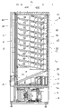
Below, with reference to accompanying drawing, the automatic vending machine of embodiment of the present invention is described.Fig. 1 is that Fig. 2 is the stereographic map in the expression commodity storehouse as the side view of automatic vending machine of sale tinned drink, bottled drink of an example that is the automatic vending machine of object with the present invention.As shown in the figure, this automatic vending machine is made up of main body rack that forms as the heat insulation framework of open at its front 1 and the external door 2 that can be supported in the front of main body rack 1 with opening and closing.Heat insulation inside door 3 sealings that the front in the commodity storehouse of main body rack 1 can be opened and closed.Aforementioned body rack 1 is in the inboard of the outer container that steel plate is processed, is the heat insulating panel that is made up of polyurethane foam plastics (urethane foam) to be set and the heat insulation framework that constitutes on upper wall 1a, left and right sides sidewall 1b, back of the body wall 1c and the diapire 1d.Formed a plurality of commodities chamber A1, A2 by heat insulation dividing plate 100 (with reference to Fig. 2) along latter in the commodity storehouse of the heat insulating panel of aforementioned body rack 1 encirclement; As shown in Figure 2; In this commodity chamber A1, A2, take in respectively and be provided with commodity accomodation frame 4, this commodity accomodation frame 4 is included on the left and right directions to be arranged a plurality of and on above-below direction, is set to the commodity shelf 42 of multilayer.In this embodiment, in the A1 of commodity chamber, take in a commodity accomodation frame 4 is set, in the A2 of commodity chamber, take in and be provided with two commodity accomodation frames 4.In addition, in Fig. 2, omitted the upper wall 1a that is arranged at main body rack 1 with after the Machine Room 8 of bottom of the main body rack 1 stated.
Above-mentioned commodity accomodation frame 4 comprise set up commodity shelf 42 about framework lateral plate 41.Framework lateral plate 41 about this is that the thin plate steel plate of rectangular flat shape is processed; In this embodiment, constitute by the place ahead one side frame side plate 41F of separate front and back (below be called the first framework lateral plate 41F) and rear side framework lateral plate 41R (below be called the second framework lateral plate 41R).Corresponding with this first framework lateral plate 41F and the second framework lateral plate 41R, above-mentioned commodity shelf 42 also as after state shown in Figure 9 by separate front and back, but be generically and collectively referred to as commodity shelf 42 here.And; Commodity shelf 42 front and back of front and back link to each other; And the place ahead one side according to as commodity input port 44 is high, take out of mouthfuls 45 the low mode of rear side as commodity, under the state that the gradient with regulation tilts, is set up in the first framework lateral plate 41F and the second framework lateral plate 41R.In addition, be provided with the top guide device 40 (in Fig. 2, expression has the top guide device 40 in left side, and the top guide device on right side is hidden in framework lateral plate 41 and can't sees) of the pair of right and left that the commodity shelf 42 before and after striding extends along fore-and-aft direction.By the commodity shelf of front and back 42 with about the inner space that surrounds of a pair of top guide device 40 constitute with the posture of laying across take in the commodity accommodating passage 43 (commodity post) of a plurality of commodity with forming a line along fore-and-aft direction, this commodity accommodating passage 43 (commodity post) forms multilayer (being 10 commodity posts) up and down in this embodiment.The commodity accomodation frame 4 that constitutes like this is set side by side with a plurality of in the commodity storehouse along left and right directions.The commodity of above-mentioned each commodity accommodating passage 43 take out of mouthfuls 45 near, the top of each commodity accommodating passage 43; In this embodiment, below the commodity shelf 42 of upper strata one side, be provided with and take out of the commodity carrying out device 5 that is accommodated in the commodity G in this commodity accommodating passage 43 one by one.And; Rearward end at the commodity shelf 42 of each layer is equipped with ability of posture control plate 47, and this ability of posture control plate 47 is above-mentionedly taken out of the extrusion position of passage 46 and pushed open by the commodity that are fallen G and rotate from taking out of between the retreating position that passage 46 keeps out of the way being projected into.About this ability of posture control plate 47; According to towards take out of the outstanding mode of passage 46 by after the coil spring 474 (with reference to Figure 14) stated apply power; Have when by taking out of that commodity G that passage 46 falls pushes open from taking out of passage 46 when keeping out of the way, be that the posture of laying across and the energy that falls that absorbs these commodity G are to reduce the function of its speed of fall with the correcting posture of these commodity G.In addition; The upper end of commodity accomodation frame 4 through the framework lateral plate 41 about will making towards the outside acutangulate hook sheet 41F2 that the ground bending forms, 41R2 (with reference to after Fig. 6 of stating) hang over the end face in the commodity storehouse that is arranged in the main body rack 1 and the track component R that extends along fore-and-aft direction on, thereby be arranged in the commodity storehouse.
The commodity that are arranged to multilayer the commodity accommodating passage 43 of above-mentioned each commodity accomodation frame 4 are up and down taken out of mouthfuls 45 and are positioned on the same plumb line; And above-mentioned commodity take out of mouthfuls 45 with the back side, commodity storehouse (back of the body wall 1c of main body rack 1) between to be provided with xsect that card only is fixed in the second framework lateral plate 41R be that the passage of コ word shape forms parts 10, the inner space of these passage formation parts 10 forms that commodity G fallen takes out of passage 46.In addition, form the back of the body wall of parts 10 at this passage, according to the relative mode in centre position of the ability of posture control plate 47 of adjacency up and down, a side is provided with the projection 11 of a plurality of convexs along above-below direction forwardly.
The bottom card that forms parts 10 at above-mentioned passage only has guiding parts 20, and said guiding parts 20 connects the commodity of taking out of passage 46 and being disposed at the bottom of commodity accomodation frame 4 and takes out of chute 6.This guiding parts 20 has according to the commodity G that in taking out of passage 46, roughly falls along vertical direction takes out of the chute 6 mode channeling conduct of conversion direction successfully towards commodity, and relaxes the function of the drop impact of the commodity G that falls.Above-mentioned commodity take out of chute 6 be before low posture be disposed at the bottom of commodity accomodation frame 4 and on its plate face perforation a plurality of air holes are arranged.These commodity are taken out of chute 6 and are taken out of mouth 31 through the commodity that are arranged at the band baffle plate on the heat insulation inside door 3, connect above-mentioned commodity take-out port 21 of taking out of passage 46 and external door 2.In addition; In the bottom that above-mentioned commodity are taken out of chute 6 is provided with the commodity storehouse, cool off or heat and will be accommodated in the cooling unit 7 that commodity accomodation frame 4 commodity G are kept at cold or hot state, be provided with back side pipeline 13 mutually with the wind-tunnel 7a of this cooling unit 7.In addition, in the Machine Room 8 of the bottom of main body rack 1, be provided with the cooling unit and the refrigerating machine condensation unit 9 that forms freeze cycle of cooling unit 7.
In addition, omitted among the figure, but be provided with through dropping into currency the required parts of vending articles G automatically in the front of external door 2: show have with the storehouse that is accommodated in main body rack 1 in the commodity displaying chamber of the corresponding a plurality of commodity samples of commodity G; Specify the commodity selection button of the commodity G that is bought; Input is as the coin slot of the coin of token; Insertion is inserted mouth as the bank note of the bank note of token; Be used for taking out the small change coin or return mouthful according to the coin of returning the coin that instruction returned; With the return bar of indication small change or the return that inserts coin etc., also be provided with the external door 2 airtight handles that are locked in the door lock mechanism on the main body rack 1 in addition etc.
Top at the back of the body wall 1c in the commodity storehouse of aforementioned body rack 1 is provided with upstream line 14, in this embodiment, all is provided with upstream line 14 at each commodity accomodation frame 4.This upstream line 14 is used to suck the indoor air of commodity, through in the Fig. 3 that follows the side pipeline 15 that will explain return back side pipeline 13 (cooling unit 7).Below, use Fig. 3 to form from above-mentioned cooling unit 7 blow out be heated or cooled after the pipeline configuration of circulating path of air describe.In addition, Fig. 3 has represented from Fig. 2, to remove the state after commodity accomodation frame 4, commodity are taken out of chute 6 and wind-tunnel 7a (cooling unit 7).
In Fig. 3,13 and 14 represent back side pipeline and upstream line once more, the 15th, and the side pipeline.The front (inside-of-refrigerator) of pipeline 13 forms the opening 131 be communicated with wind-tunnel 7a (cooling unit 7) at the above-mentioned back side, overleaf pipeline 14 below be formed with the storehouse in the suction inlet (not shown) that is communicated with.Above-mentioned side pipeline 15 lays that inner bottom part erects towards top from the storehouse for the side along commodity chamber A2 one side of left and right sides sidewall 1b, 1b and the heat insulation dividing plate 100 of main body rack 1.Side pipeline 15 constitutes that the inner bottom part side is communicated with back side pipeline 13 in the storehouse, and one side is communicated with upstream line 14 on top.Here; In taking in the narrower commodity chamber A1 that is provided with a commodity accomodation frame 4; Side pipeline 15 is layed on the side, in this embodiment, is layed in from the front to see on the sidewall 1b in left side, in taking in the commodity chamber A2 of the broad that is provided with two commodity accomodation frames 4; Side pipeline 15 is layed on the left and right side, in this embodiment, is layed in from the front to see on the side of commodity chamber A2 one side of sidewall 1b and heat insulation dividing plate 100 on right side.In the A2 of the commodity chamber of broad; The reason that side pipeline 15 is layed on the left and right side is; Corresponding with two commodity accomodation frames 4; The circulating path of air in the storehouse is dispersed into two, can makes in the storehouse air circulation in two commodity accomodation frames 4 fully, and cooling or heating are accommodated in the commodity G of two commodity accomodation frames 4 effectively.Like this, in the A1 of commodity chamber, be equipped with a upstream line 14 that is communicated with side pipeline 15, in the A2 of commodity chamber, be equipped with about two upstream lines 14,14 of being communicated with respectively of side pipeline 15,15.In addition; In Fig. 3; 101~104 are formed by panel beating respectively; Be to cover the guard block that the surface of left and right sides sidewall 1b that the heat insulating panel by isocyanurate foam constitutes, 1b, back of the body wall 1c, heat insulation dividing plate 100 is protected, constitute with screw back side pipeline 13, upstream line 14 are fastened on this guard block 101~104.
In pipeline configuration shown in Figure 3, upstream line 14 is layed in and is formed at originally is exactly in the vacant space (dead space) (free space) on rear side top in commodity storehouse of tilting rack.Promptly; As shown in Figure 1; On taking in the commodity accomodation frame 4 that is arranged in the commodity storehouse, set up high according to the place ahead one side as commodity input port 44, take out of the commodity shelf 42 of the state that the low mode of mouthfuls 45 rear side tilts with the gradient of regulation as commodity, therefore produce free space on the rear side top in commodity storehouse; But in this embodiment, upstream line 14 is layed in the above-mentioned free space.And side pipeline 15 is arranged at the left and right side in the storehouse.According to this structure, remove and in existing apparatus, be arranged in the storehouse air circulation at the back side and use pipeline, thereby can enlarge the fore-and-aft direction zone in the storehouse, that is, can prolong commodity accommodating passage 43, therefore can increase commodity quantity.
Then, use Fig. 4 that the structure of commodity accomodation frame 4 is described.Fig. 4 representes to take in the commodity accomodation frame 4 of seeing the left side from the front that is arranged among the commodity chamber A2 (with reference to Fig. 2).This commodity accomodation frame 4 is made up of following: the pair of right and left framework lateral plate 41 that is made up of the first framework lateral plate 41F and the second framework lateral plate 41R of separate front and back; Be set up in respectively the above-mentioned first framework lateral plate 41F and the second framework lateral plate 41R the place ahead one side commodity shelf 42F (below; It is called the first commodity shelf 42F) and rear side commodity shelf 42R (below, it is referred to as the second commodity shelf 42R); Stride that this first commodity shelf 42F and the second commodity shelf 42R ground are provided with and with the first commodity shelf 42F and the second commodity shelf 42R link about one group top guide device 40 (the top guide device on right side is called 40R; The top guide device in left side is called 40L, they are generically and collectively referred to as top guide device 40); The xsect that card only is fixed on the above-mentioned second framework lateral plate 41R is the passage formation parts 10 of コ word shape; End the guiding parts 20 etc. that forms the lower end of parts 10 at this passage with card.
As shown in Figure 5, the framework lateral plate 41 about above-mentioned is made up of the first framework lateral plate 41F and the second framework lateral plate 41R of the thin plate steel plate system of rectangular flat shape.Except compare with the first framework lateral plate 41F the second framework lateral plate 41R form the long this point, both structures are roughly the same, therefore the first framework lateral plate 41F described, for the second framework lateral plate 41R and remember reference symbol and omit explanation.In addition, Fig. 6 amplifies the right side is seen in expression from the front framework lateral plate 41, also with reference to Fig. 6 the first framework lateral plate 41F is described.
The first framework lateral plate 41F forms the front and back of the thin plate steel plate of rectangular flat shape and the outside bending of lower limb and strengthens flange (flanging: flange) 41F1 (41R1), on top edge is formed with the clamping hooked 41F2 (41R2) that outwards acutangulates bending.In addition, on the plate face of the first framework lateral plate 41F, paired stop hole 41F3 (41R3) before and after multilayer ground forms up and down, the one group of stop hole 41F3 in front and back (41R3) have ladder respectively.Above-mentioned stop hole 41F3 (41R3) is formed with two at each layer respectively along above-below direction discretely.Above-mentioned stop hole 41F3 (41R3) is used for setting up commodity shelf 42; Under with the first framework lateral plate 41F and the second framework lateral plate 41R situation (under the situation of the short automatic vending machine of depth) near configuration; Utilize the stop hole 41F3 (41R3) of upper strata one side; In (under the situation of the long automatic vending machine of depth) under the situation of the first framework lateral plate 41F being separated setting with the second framework lateral plate 41R, utilize the stop hole 41F3 (41R3) of lower floor's one side.This is that the angle of inclination that all will be set up in the commodity shelf 42 on this first framework lateral plate 41F and the second framework lateral plate 41R remains necessarily under the situation with the first framework lateral plate 41F and the approaching perhaps configured separate of the second framework lateral plate 41R.In addition, the stop hole 41R3 of the rear side among the second framework lateral plate 41R is circular with respect to the stop hole 41R3 of the place ahead one side, and forms the hook-type of L word shape.In addition, being formed on the antemarginal reinforcement flange 41R1 of the second framework lateral plate 41R, be formed with a plurality of threaded holes (female screw) 41R4, and one side is formed with embedded hole 41R5 on top along above-below direction.
The clamping hooked 41F2 (41R2) that is formed at the coboundary of the first framework lateral plate 41F engages with track component R, the R (with reference to Fig. 4) of end face in commodity storehouse in being layed in main body rack 1.Above-mentioned track component R, R form left-right symmetric, shown in Fig. 4 (a) amplifies, form by horizontal part R1 with along the R2 of the portion that hangs down of vertical ground of the length direction bending of this horizontal part R1, comprise from the lower end of the R2 of portion that hangs down the hook portion R3 that direction to the inside folds.Above-mentioned track component R, R are configured to frame parts (not shown) that horizontal part R1 is fixed on the end face that is formed at the commodity storehouse by screw thread and go up and extend along fore-and-aft direction.The front end of the hook portion R3 of above-mentioned track component R forms slide with it slipping plane of (slide move) of above-mentioned clamping hooked 41F2 (41R2) with engaging, and is as shown in Figure 7, on this slipping plane, is formed with detent R31, R32.Fig. 7 is for the track component R that sees the left side from the front, from the side view of the track component R unilateral observation on another (right side).Above-mentioned detent R31, R32 form the convex than the high one-level of slipping plane (a section) of track component R, and are set to clamping hooked 41R2 and just in time embed the size between detent R31, the R32.Be sticked at clamping hooked 41F2 (41R2) under the situation of hook portion R3 engaging of track component R framework lateral plate 41; The detent R31 of above-mentioned track component R, R32 take in the function that commodity accomodation frame 4 is set except the assigned position that has in the commodity storehouse, and the first framework lateral plate 41F and the second framework lateral plate 41R that also has the separate front and back of preventing is along the fore-and-aft direction skew and the function of mutual spacing bias.
In addition, the lower end rear side at the first framework lateral plate 41F is fastened with the locating guider 41G (with reference to Fig. 5, Fig. 6) that is formed by panel beating.41G is as shown in Figure 8 for this locating guider; So that be formed with threaded hole (female screw) 41G31 on the hooking sheet 41G3 of the each other inside mode bending of the front end of the 41G2 of bridge formation portion, bending forms the said bridge formation 41G2 of portion towards the top with the right ends of the baseplate part 41G1 of rectangle.Rear end one side of the 41G1 of aforesaid substrate portion excised left and right sides ora terminalis and form than about the 41G2 of bridge formation portion between size short, and the edge is formed with the curling shape rib 41G11 that is rolled into hollow cylinder shape (shape curls) in its back-end.Should curl shape rib 41G11 left and right directions length than about the size between the second framework lateral plate 41R of configuration is slightly short relatively, form about just in time embedding the length between the second framework lateral plate 41R of configuration relatively.Above-mentioned locating guider 41G is as shown in Figure 6; Hooking sheet 41G3 about making is along the antemarginal reinforcement flange 41F1 that is formed at the first framework lateral plate 41F, and the curling shape rib 41G11 that will be formed at the back edge of substrate 41G1 then embeds between the second framework lateral plate 41R.At this moment, the rear end side of substrate 41G1 about breach will be along the outer wall of the reinforcement flange 41R1 of the front edge that is formed at the second framework lateral plate 41R and the inwall of the second framework lateral plate 41R.Like this; Be provided with under the state of locating guider 41G according to the mode of striding the first framework lateral plate 41F and the second framework lateral plate 41R; When making screw S1 (with reference to Fig. 6) be combined on threaded hole (female screw) 41G31 of hooking sheet 41G3 through the antemarginal reinforcement flange 41F1 that is formed at the first framework lateral plate 41F, locating guider 41G strides the first framework lateral plate 41F and the second framework lateral plate 41R links both.Therefore, this locating guider 41G has following function: with about relatively the framework lateral plate 41F, the interval of 41R of configuration remain on the interval of regulation, and prevent that the first framework lateral plate 41F of separate front and back and the second framework lateral plate 41R from squinting on left and right directions.
Then; Fig. 9 representes to be set up in respectively the first commodity shelf 42F, the second commodity shelf 42R of the above-mentioned first framework lateral plate 41F, the second framework lateral plate 41R and one group the state of top guide device 40 about being assembled with on this first commodity shelf 42F, the second commodity shelf 42R.The top guide device 40 of above-mentioned pair of right and left is made up of top guide device 40R that is positioned at the right side and the top guide device 40L that is positioned at the left side; Stride the first commodity shelf 42F, the setting of the second commodity shelf 42R ground respectively, and form commodity accommodating passage 43 with the mode of extending along fore-and-aft direction.Here; In most of the cases; Through make be positioned at the left side movable top guides 40L approaching with the fixed, top guides 40R that is positioned at the right side, separate; Commodity accommodating passage 43 is set at the channel width of the length (width) that meets commodity, and the fixed, top guides 40R that below will be positioned at the right side is called fixed, top guides 40R, and the movable top guides 40L that will be positioned at the left side is called movable top guides 40L.In addition, in Fig. 9, pull down the ability of posture control plate 47 of the rearward end that is provided to the second commodity shelf 42R.
Also the above-mentioned first commodity shelf 42F and the second commodity shelf 42R are described with reference to Figure 10.The first commodity shelf 42F and the second commodity shelf 42R adopt rectangular steel plates to process respectively; About the first commodity shelf 42F and the common part of the second commodity shelf 42R; The first commodity shelf 42F is described, for the second commodity shelf 42R and remember reference marks and omit explanation.
The above-mentioned first commodity shelf 42F (42R) is shown in figure 10; Formation is from flange 42FA, the 42FB (42RA, 42RB) of its left and right sides edge bending downwards; And realized that intensity enhancing is (in Fig. 9; The flange 42FA (42RA) that is formed at left side edge is hiding and invisible, for flange 42RA, and the Figure 25 (b) that states after the reference).Be formed with threaded hole (female screw) 42FA1,42FB1 (42RA1,42RB1) respectively at above-mentioned flange 42FA, 42FB (42RA, 42RB).Front end at the first commodity shelf 42F (42R) forms the bolster 42F1 (42R1) that is rolled into hollow cylinder shape (shape curls), and the right ends of bolster 42F1 (42R1) forms outwards more outstanding than flange 42FA, 42FA (42RA, 42RA) respectively.In addition, form the bolster 42F2 that is rolled into hollow cylinder shape (shape curls) in the rear end of the first commodity shelf 42F, the right ends of bolster 42F2 forms outwards more outstanding than flange 42FA, 42FB respectively.And; Locating on the front of the plate face of the first commodity shelf 42F; Run through the handle hole 42F3 of the wide cut that setting extends along left and right directions and be communicated with the hole 42F4 that is slidingly fastened of joint-cutting in a narrow margin in the rear end of the joint-cutting (slit) of wide cut; The plate face of the first commodity shelf 42F lean on the place, rear, the front end that runs through the joint-cutting that is arranged on wide cut is communicated with the hole 42F5 that is slidingly fastened of joint-cutting in a narrow margin.
Be provided with the maintaining part 42R2 (Figure 25 that also states after the reference) of the groove shape that forms through bending in the rear end of the above-mentioned second commodity shelf 42R.The commodity carrying out device of stating after this maintaining part 42R2 is used for keeping 5.The right ends of above-mentioned maintaining part 42R2 forms supporting slice 42R21, the 42R21 that compares outwards outstanding L word shape with flange 42RA, 42RB respectively.In addition, on the plate face of the second commodity shelf 42R, run through the setting slot 42RH that is provided with a plurality of joint-cutting shapes that extend along fore-and-aft direction along left and right directions.It is paired before and after the setting slot 42RH of this joint-cutting shape forms.And, mosaic process 42R3, the 42R4 of the arch that forms the locating on the front to be formed with extruding of the plate face of the second commodity shelf 42R towards the back side.The middle body (arcuate part) of this mosaic process 42R3,42R4 is protuberance from the back side of the second commodity shelf 42R, forms the through hole that the front end of card claw stop 501,502 of the substrate 50 of commodity carrying out device 5 can pass through.And, the arc projection 567 in the Lock Part 566 of first detent (retainer) 56 of the commodity carrying out device of after the rear end of the plate face of the second commodity shelf 42R is formed with, stating shown in Figure 22 5 with about three bleed hole 42R5 being connected of direction protrusion 568,568.
The above-mentioned first commodity shelf 42F is erected at the first framework lateral plate 41F according to following mode.That is, bolster 42F1, the 42F2 of the outstanding to the left and right front and back among the first commodity shelf 42F embedded respectively among the paired stop hole 41F3 in the plate face that is formed at the first framework lateral plate 41F and front and back, the 41F3.Thus, the first commodity shelf 42F is erected at the first framework lateral plate 41F.Equally, the second commodity shelf 42R embeds bolster 42R1 and supporting slice 42R21 respectively among the stop hole 41R3,41R3 of the second framework lateral plate 41R.Thus, the second commodity shelf 42R is erected at the second framework lateral plate 41R.And; Threaded hole (female screw) 42FA1,42FB1 (42RA1,42RB1) at each flange 42FA that is formed at the first commodity shelf 42F and the second commodity shelf 42F, 42FB (42RA, 42RB) screw screw through the first framework lateral plate 41F, the second framework lateral plate 41R.In this case; In this embodiment, only constitute that the first commodity shelf 42F, the first commodity shelf 42F that is positioned at upper strata, middle level, lower floor of the second commodity shelf 42R, the second commodity shelf 42R of multilayer carry out screw thread and fix to being arranged in up and down.Like this, all carry out the fixing situation of screw thread with the first commodity shelf 42F, the second commodity shelf 42R and compare, can cut down assembling man-hour (number) multilayer on above-below direction.
Then, Figure 11 representes fixed, top guides 40R, (a) is the stereographic map of seeing from left oblique upper, (b) is the stereographic map that oblique below is seen from a left side.It is the thin plate steel plate of L word shape that this fixed, top guides 40R adopts bending, is carried by the parallel commodity of plate face with the first commodity shelf 42F, the second commodity shelf 42R and puts the 40R1 of portion and form with the vertical side wall portion 40R2 of plate face of the first commodity shelf 42F, the second commodity shelf 42R.Carry the fitting portion 40R3 of curling shape that the front end of putting the 40R1 of portion (under shown position, being right tiltedly front end) is formed with the big circle of bolster 42F1 of the hollow cylinder shape (shape curls) than the first commodity shelf 42F at above-mentioned commodity.This fitting portion 40R3 form the parcel first commodity shelf 42F hollow cylinder shape (curl shape) bolster 42F1 periphery 3/4ths 3/4ths circular; And with the chimeric state of above-mentioned bolster 42F1 under, move about embed among this bolster 42F1 and along about be free to slide mobile.In addition, carry locating on the front in the plate face of putting the 40R1 of portion, erect through incision and be formed with towards the back side one side-prominent hook sheet 40R11 at commodity.And, carry at commodity and to lean on the place, rear in the plate face of putting the 40R1 of portion, erect through incision and be formed with towards the back side one side-prominent a pair of engaging pawl 40R12, the 40R12 in front and back.This engaging pawl 40R12,40R12 form under the situation of observing from the side and are roughly V word shape.A pair of engaging pawl 40R12, the 40R12 in these front and back can engage, break away from a pair of setting slot 42RH, the 42RH in the front and back of the plate face that is formed at the above-mentioned second commodity shelf 42R.
Then, Figure 12 representes movable top guides 40L, (a) is the stereographic map of seeing from right oblique upper, (b) is the stereographic map that oblique below is seen from the right side.This movable top guides 40L adopts the thin plate steel plate be bent into L word shape, is carried by the parallel commodity of plate face with the first commodity shelf 42F, the second commodity shelf 42R and puts the 40L1 of portion and form with the vertical restrictions 40L2 of plate face of the first commodity shelf 42F, the second commodity shelf 42R.Carry that the front end of putting the 40L1 of portion (under shown position for a left side tiltedly front end) is formed with big two circles of bolster 42F1 (big two-stage) of the hollow cylinder shape (shape curls) than the first commodity shelf 42F and than the fitting portion 40L3 of the curling shape of the big circle of fitting portion 40R3 of the curling shape of said fixing top guide device 40R at above-mentioned commodity.This fitting portion 40L3 form the parcel first commodity shelf 42F hollow cylinder shape (curl shape) bolster 42F1 periphery 3/4ths 3/4ths circular; And with the chimeric state of above-mentioned bolster 42F1 under; Move about embed among this bolster 42F1 and along about be free to slide mobilely, and form among the fitting portion 40R3 of the curling shape that embeds above-mentioned fixed, top guides 40R of moving about.In addition; Carry ratio pars intermedia in the plate face of putting the 40L1 of portion near the place ahead one side at commodity; Erect through incision and to be formed with towards the back side one side-prominent hook sheet 40L11, and be formed with towards the back side one side-prominent a pair of engaging pawl 40L12, the 40L12 in front and back leaning on the place, rear to erect through incision.This engaging pawl 40L12,40L12 form under the situation of observing from the side and are roughly V word shape.A pair of engaging pawl 40L12, the 40L12 in these front and back can engage, break away from a pair of setting slot 42RH, the 42RH in the front and back of the plate face that is formed at the above-mentioned second commodity shelf 42R.
Said fixing top guide device 40R is assembled on the first commodity shelf 42F and the second commodity shelf 42R according to following mode.Promptly; From the top of the first commodity shelf 42F and the second commodity shelf 42R, the commodity that are formed at fixed, top guides 40R are carried the hook sheet 40R11 that puts the 40R1 of portion insert in the wide cut joint-cutting that leads to the sheet 42F4 that is slidingly fastened on the plate face that is formed at the first commodity shelf 42F with relative mode.Under this state, the bolster 42F1 that the fitting portion 40R3 of fixed, top guides 40R is positioned at than the first commodity shelf 42F compares position on the front.Afterwards, make fixed, top guides 40R rearward during a side shifting, the fitting portion 40R3 of fixed, top guides 40R will carry out chimeric with the mode of the periphery of the bolster 42F1 that surrounds the first commodity shelf 42F.At this moment, the vertical part of hook sheet 40R11 moves to the rear in the wide cut joint-cutting of hole 42F4 that is slidingly fastened after, arrive and the open surface consistent location of joint-cutting in a narrow margin, the horizontal component of hook sheet 40R11 is positioned at rear one side of wide cut joint-cutting.Under this state; If hand unclamps from fixed, top guides 40R; So fixed, top guides 40R can become the engaging pawl 40R12 butt second commodity shelf 42R the plate face and from the state of the first commodity shelf 42F, second commodity shelf 42R protuberance; In addition, the horizontal component of hook sheet 40R11 separates from the back side of the first commodity shelf 42F.
From above-mentioned state at the back side of the first commodity shelf 42F one side rotate hand; Under palm state up,, and carry the horizontal component of putting 40R1 of portion or hook sheet 40R11 with forefinger or middle finger by the commodity of the fixed, top guides 40R that sees at handle hole 42F3 and upwards press from the first commodity shelf 42F with the place ahead one side of thumb press fitting portion 40R3.So fixed, top guides 40R is that fulcrum rotates to the top with its fitting portion 40R3, engaging pawl 40R12 separates from the plate face of the second commodity shelf 42R.The rotation to the top of fixed, top guides 40R is limited at the back side of the horizontal part butt first commodity shelf 42F through hook sheet 40R11.With fixed, top guides 40R to above when fixed, top guides 40R being slided to the right under the state that rotates; Fitting portion 40R3 slides on the bolster 42F1 of the first commodity shelf 42F, and the vertical part of hook sheet 40R11 gets in the joint-cutting in a narrow margin of the hole 42F4 that is slidingly fastened.And; Fixed, top guides 40R is slided to the right; Divide until the vertical portion of hook sheet 40R11 near the right-hand member of the joint-cutting in a narrow margin that arrives the hole 42F4 that is slidingly fastened; According to the setting slot 42RH that makes engaging pawl 40R12, engaging pawl 40R12 and the second commodity shelf 42R, the chimeric mode of setting slot 42RH, 42RH of right-hand member side among the 42RH, be that fulcrum rotates fixed guider 40R downwards then with fitting portion 40R3.Thus; The commodity of fixed, top guides 40R carry puts the 40R1 of portion under the state of the plate face that is close to the first commodity shelf 42F, the second commodity shelf 42R; Link with the first commodity shelf 42F, the second commodity shelf 42R, and be set at the position (fixed position) of low order end one side of the first commodity shelf 42F, the second commodity shelf 42R.
The assembling of above-mentioned movable top guides 40L to the first commodity shelf 42F and the second commodity shelf 42R; Assembling with respect to said fixing top guide device 40R to the first commodity shelf 42F and the second commodity shelf 42R; Except the hook sheet 40L11 that makes movable top guides 40L engages this point with the hole 42F5 that is slidingly fastened that leans on the place, rear of the plate face of the first commodity shelf 42F; All the other are identical, therefore omit the explanation of repetition here.This movable top guides 40L can only move the length scale of the left and right directions of the hole 42F5 that is slidingly fastened among the first commodity shelf 42F along horizontally slipping; Through making it mobile, approaching with the fixed, top guides 40R that is arranged at the said fixing position, separate along horizontally slipping.Therefore; With fixed, top guides 40R (side wall portion 40R2) is the reference position; Movable top guides 40L (restrictions 40L2) is slided move to the position of only separating the width corresponding from this fixed, top guides 40R (side wall portion 40R2) with the length (width) of the commodity of sale; Setting slot 42RH, the 42RH of engaging pawl 40L2,40L2 and the second commodity shelf 42R are provided with chimericly; Between fixed, top guides 40R (side wall portion 40R2) and movable top guides 40L (restrictions 40L2), the commodity accommodating passage 43 with channel width corresponding with the width of the commodity of selling forms along the state of fore-and-aft direction extension thus.In addition; Make under the situation of movable top guides 40L near fixed, top guides 40R; Around the fitting portion 40R3 of the fitting portion 40L3 covering fixed, top guides 40R of movable top guides 40L; The commodity of movable top guides 40L carry and put the commodity that the 40L1 of portion goes up fixed, top guides 40R and carry the top of putting the 40R1 of portion on the other hand, and both commodity carry put the 40L1 of portion and commodity carry put about the 40R1 of portion overlapping.
Here; Among two commodity accomodation frames 4 taking in the commodity chamber A2 that is arranged at Fig. 2; From the front see the right side commodity accomodation frame 4 (below; This commodity accomodation frame is called 4R) shared in the sale of the commodity below the half-size scale of half length of the commodity of the commodity of long size and above-mentioned long size (below, only be called the commodity of half-size scale).Figure 13 (a) expression: the first commodity shelf 42F among this commodity accomodation frame 4R, the second commodity shelf 42R; The first commodity shelf 42FF among this commodity accomodation frame 4R, the second commodity shelf 42RR; With the state of in this first commodity shelf 42FF, the second commodity shelf 42RR, having assembled top guide device 40, the first commodity shelf 42FF, the second commodity shelf 42RR of top guide device 40 pulled down in Figure 13 (b) expression.Moreover, in Figure 13, mark identical symbol to having with the parts of parts identical functions shown in Figure 10.
Shown in Figure 13 (a), in order to take in the commodity of half-size scale about can be in commodity accommodating passage 43 discretely, top guide device 40 is by constituting with lower component: the fixed, top guides 40RR that the right wing line is used; The movable top guides 40MR paired with said fixing top guide device 40RR; The fixed guider 40ML that left side route is used; With the movable top guides 40LL paired with said fixing top guide device 40ML.On the other hand, shown in Figure 13 (b), the first commodity shelf 42FF, the second commodity shelf 42RR are equivalent to be set side by side with two first commodity shelf 42F shown in Figure 10, the mode of the second commodity shelf 42R along left and right directions respectively.Promptly; Locating on the front of the plate face of the first commodity shelf 42FF; Being divided into the right wing line is provided with handle hole 42F3 and is slidingly fastened hole 42F4 with running through respectively with left route land used; In addition, the plate face of the first commodity shelf 42FF lean on the place, rear, be divided into the right wing line with and left route land used run through respectively and be provided with the hole 42F5 that is slidingly fastened that is communicated with joint-cutting in a narrow margin at the front end of the joint-cutting of wide cut.And, at the plate face of the second commodity shelf 42RR, be divided into right wing line usefulness and left route land used and run through the setting slot 42RH that is provided with the paired joint-cutting shape in front and back respectively.
The state that is provided with of the top guide device 40 when selling the commodity of half-size scale among the above-mentioned commodity accomodation frame 4R is shown in Figure 13 (a).Promptly; The fixed, top guides 40RR that the right wing line is used is set at the right end position of the first commodity shelf 42FF, the second commodity shelf 42RR; On the other hand, be set at the substantial middle position of the first commodity shelf 42FF, the second commodity shelf 42RR with the paired movable top guides 40MR of said fixing top guide device 40RR.In addition; The left side of the movable top guides 40MR that the left side fixed, top guides 40ML that uses of route uses in the substantial middle position of the first commodity shelf 42FF, the second commodity shelf 42RR and at the right wing line is provided with side by side; On the other hand, be set at the left position of the first commodity shelf 42FF, the second commodity shelf 42RR with the paired movable top guides 40LL of said fixing top guide device 40ML.Thus; Between fixed, top guides 40RR and the movable top guides 40MR and between fixed, top guides 40ML and movable top guides 40LL, form the commodity accommodating passage 43 that two row have the channel width corresponding with the width of the commodity of half-size scale respectively according to the mode of extending along fore-and-aft direction.Moreover, under the situation of selling the commodity shorter, movable top guides 40MR or movable top guides 40LL are configured slidably to right-hand than half-size scale.
When in above-mentioned commodity accomodation frame 4R, selling the commodity of long size, be set at the top guide device 40 of the position of Figure 13 (a) according to following mode adjustment.That is the movable top guides 40MR that, the right wing line is used makes it near fixed, top guides 40RR to right-hand slip.In this case, the commodity of movable top guides 40MR carry and put commodity that the 40MR1 of portion goes up fixed, top guides 40RR and carry and put the 40RR1 of portion and go up and become overlapping up and down.Like this; This engaging pawl 40MR12 is formed at and carries only squint the to the left commodity of fixed, top guides 40RR of the right-hand member of putting the 40MR1 of portion from commodity and carry the position of horizontal wide (size of left and right directions) of putting the 40RR1 of portion; Even make commodity at movable top guides 40MR carry to put that the commodity to fixed, top guides 40RR carry under the situation of putting on the 40RR1 of portion on the 40MR1 of portion, the engaging pawl 40MR12 of movable top guides 40MR also can engage with setting slot 42RH, the 42RH of the joint-cutting shape of the second commodity shelf 42RR.As stated; The movable guide 40MR that the right wing line is used is arranged on and the position is set to right-hand slip and near the position of fixed, top guides 40RR from Figure 13 (a); On the other hand, the fixed, top guides 40ML that left route is used is set in it is slided and near the position of movable top guides 40LL to left.In this case, the commodity of fixed, top guides 40ML carry commodity that the portion 40ML1 of putting pierces fixed, top guides 40LL carry put become under the 40LL1 of portion overlapping up and down.Thus, between the fixed, top guides 40ML that movable top guides 40MR that the right wing line is used and left route are used, form commodity accommodating passage 43 with the mode of extending with channel width corresponding with the width of the commodity of growing size along fore-and-aft direction.
In addition; About the second commodity shelf 42RR in above-mentioned commodity accomodation frame 4R two commodity carrying out device 5 (with reference to Fig. 1) are set side by side; Under the situation of the commodity of selling half-size scale, two commodity carrying out device 5 are moved, on the other hand respectively; Under the situation of the commodity of selling long size, carry out synchro control and make two commodity carrying out device 5 move simultaneously.
Then, Figure 14 representes to be provided to the ability of posture control plate 47 of the rear end of the second commodity shelf 42R, and (a) expression is with the state of ability of posture control plate 47 after the second commodity shelf 42R installs, and (b) state of ability of posture control plate 47 has been decomposed in expression.Ability of posture control plate 47 is processed goods of the rectangle thin plate steel plate of growing crosswise, below be bent on the plate face of ability of posture control plate 47 of convex and be formed with many reinforcements (rib) 471 through extruding.Base end side at ability of posture control plate 47 is provided with the bearing 472,472 that is rolled into hollow cylinder shape (shape curls) and forms.In above-mentioned bearing 472,472, insert the axle 473 of pole shape.In addition, in above-mentioned pair of bearings 472, be provided with coil spring 474 between 472, in the hollow bulb of this coil spring 474, insert above-mentioned axle 473.Therefore, above-mentioned coil spring 474 is kept by axle 473.
On the other hand, be formed with three peristome 42Ra, 42Rb, 42Rc after excising the rib of back edge of the second commodity shelf 42R.In addition; At two adjacents of peristome 42Ra, 42Rb, 42Rc, be formed with to cut to rear side (side opposite) and erect and towards hook sheet 42Rd, the 42Re at rear with the surface channel of the second commodity shelf 42R from the surface channel of the second commodity shelf 42R.And, be formed with the brake(-holder) block 42Rf that incision erects towards the place ahead in the side of hook sheet 42Re.The bearing 472,472 of the pair of right and left of above-mentioned peristome 42Rb, 42Rc and ability of posture control plate 47 is provided with accordingly, forms the size that can admit this bearing 472,472.In addition, above-mentioned peristome 42Ra forms the size that can admit coil spring 474.And, hook sheet 42Rd, 42Re and the plate face of commodity shelf 42 between form the through hole that axle 473 connects and keep this axle 473, brake(-holder) block 42Rf is the parts of the anticreep of formation spools 473.In addition, the commodity carrying out device of stating after that locate on the front and mosaic process 42R3, the 42R4 arch that form towards back side extruding that is formed at the plate face of the second commodity shelf 42R is used for installing 5.
The installation to the second commodity shelf 42R of above-mentioned ability of posture control plate 47 is described below.Promptly; Embed under the state of peristome 42Rb, 42Rc at the bearing 472,472 of the rear side of the second commodity shelf 42 on placing operation post (being right tiltedly the place ahead one side), insert axle 473 along the back side of the rib of the rear end of the second commodity shelf 42R from the side of the second commodity shelf 42R with the pair of right and left of ability of posture control plate 47 at Figure 14.Here, through by the formed through hole of a hook sheet 42Rd (left side among the figure), and connect a bearing 472 (left side among the figure) of ability of posture control plate 47 and arrive moment of peristome 42Ra, temporarily stop the insertion of axle 473 at axle 473.Under this state, at above-mentioned peristome 42Ra hookup wire coil spring 474.In this case, coil spring 474 is being accumulated under the state of composing acting force the back side that an end is hung over the second commodity shelf 42R, on the other hand another end is hung over the back side of ability of posture control plate 47.Like this, after peristome 42Ra has installed coil spring 474, restart the insertion of axle 473.Then, behind another bearing 472 (right side among the figure) that makes above-mentioned axle 473 perforations by coil spring 474, ability of posture control plate 47, the formed through hole of another hook sheet 42Re (right side among the figure), insert it into until butt brake(-holder) block 42Rf.Thus, the ability of posture control plate 47 that is applied acting force by coil spring 474 is that the center is freely to rotate by the rearward end of pivot suspension at the second commodity shelf 42R with axle 473.
In addition; Ability of posture control plate 47 by coil spring 474 to apply acting force towards taking out of the outstanding mode of passage 46 (with reference to Fig. 1); At commodity G not under the state of butt, shown in Figure 14 (a), be maintained at the extrusion position on the extended line of surface channel of the second commodity shelf 42R.This be since the end face butt of the base end side that is formed with bearing 472,472 that is set at ability of posture control plate 47 from the plate face of the rear end bending downwards of the second commodity shelf 42R.
Here, Figure 15 is illustrated among two commodity accomodation frames 4 taking among the commodity chamber A2 that is arranged at Fig. 2, is provided to the ability of posture control plate 47 of rear end of the second commodity shelf 42RR of the commodity accomodation frame 4R that sees the right side from the front.In Figure 15, to identical with Figure 14 or have the symbol that mark is identical on the parts of identical function and omit its explanation.
Shown in figure 15, the second commodity shelf 42RR is equivalent to be set up in parallel along left and right directions respectively the mode of two second commodity shelf 42R shown in Figure 14.Promptly; Back edge at the second commodity shelf 42RR; Be formed with three peristome 42Ra, 42Rb, 42Rc respectively in left side and right side; And two adjacents at this peristome 42Ra, 42Rb, 42Rc are formed with hook sheet 42Rd, 42Re respectively, and are formed with brake(-holder) block 42Rf respectively in the side of the hook sheet 42Re on right side.The reason that does not form brake(-holder) block 42Rf in the left side is, the axle (with reference to Figure 14) that makes ability of posture control plate 47,47 general major axis in both.And the structure of ability of posture control plate 47,47 is except major axis general in both, and all the other are with shown in Figure 14 identical.Therefore, its installation is compared with installation method shown in Figure 14, and general major axis comes ability of posture control plate 47,47 this point about pivot suspension in being utilized in both, and all the other are identical with the installation method of Figure 14, therefore omits the explanation of repetition here.
Below, Figure 16 forms the stereographic map that the passage of taking out of passage 46 (with reference to Fig. 1) forms parts 10.This passage forms the bending of parts 10 through panel beating, and to form xsect be コ word shape, comprises from the right ends of back of the body wall 101 sidewall 102,102 with respect to the face bending vertically of back of the body wall 101.Be formed with the projection 11 of convex at above-mentioned back of the body wall 101 through being squeezed in the place ahead one side.Can know also that with reference to Fig. 1, Fig. 4 this projection 11 is to be provided with a plurality of with the relative mode in centre position of the ability of posture control plate 47 of adjacency up and down along above-below direction.Above-mentioned sidewall 102, the interval between 102 are consistent with the interval of the second framework lateral plate 41R of pair of right and left.Front edge at above-mentioned sidewall 102,102 forms difference flange 103,103 outwardly respectively, is provided with screw thread inserting hole 104 respectively at the both ends up and down of these flanges 103,103.In addition, be provided with hook-shaped card claw stop 105 on the front edge top of above-mentioned sidewall 102,102.Above-mentioned passage forms parts 10; Make above-mentioned card claw stop 105 breakthrough forms be formed in the embedded hole 41R5 (with reference to Fig. 6) of the antemarginal reinforcement flange 41R1 of the second framework lateral plate 41R; And 103,103 butts of the flange about making are formed at the antemarginal reinforcement flange 41R1 (with reference to Fig. 6) of the second framework lateral plate 41R; If it is slided downwards, then above-mentioned card claw stop 105 engages with above-mentioned embedded hole 41R5 then.Under this state, through about the screw thread inserting hole 104 of flange 103,103, threaded hole (female screw) 41R4 that screw (not shown) is combined on be formed at above-mentioned reinforcement flange 41R1.Thus, above-mentioned passage formation parts 10 cards only are fixed on commodity accomodation frame 4 and install integratedly.In addition, in Figure 16, the projection 11 that is formed at the back of the body wall 101 of passage formation parts 10 is expressed as along the long continuously projection of left and right directions, but also can form short projection is dispersed on the left and right directions.In this case,, can make metal pattern form miniaturization, therefore can control the expense of metal pattern with respect to metal pattern maximizes in order to form the long continuously projection 11 of left and right directions shown in Figure 16.
So, also explanation is provided to the guiding parts 20 that above-mentioned passage forms the bottom of the back of the body wall 101 in the parts 10 with reference to Figure 17.Figure 17 forms the exploded view that parts 10 have decomposed guiding parts 20 from passage.In Figure 17, represent guiding parts 20,21st with 20 once more, the installation accessory of panel beating system, the 22nd, the axle of pole shape.Above-mentioned guiding parts 20 is panel beating systems; Have than passage form the left and right sides sidewall 102 of parts 10, between 102 size slightly the baseplate part 201 of short left and right sides width form to back side lateral bending is bent and be convex, be provided with the bearing 202 that curls into to hollow cylinder shape (shape curls) dispersedly along left and right directions in the upper end of baseplate part 201.Above-mentioned installation accessory 21 bendings are vertical section L word shape, towards above the upper end of baseplate part 211, curl into to the bearing 210 of hollow cylinder shape (shape curls) and be provided with dispersedly with mode with bearing 202 engagements of above-mentioned guiding parts 20.Support 212 towards the place ahead of above-mentioned installation accessory 21 is provided with a plurality of threaded holes (female screw) 2121.On the other hand, the lower end of the back of the body wall 101 in passage formation parts 10 is formed with the flange 1011 towards the place ahead.This flange 1011 is formed with a plurality of screw thread inserting holes 1012 as the base that accessory 21 is installed.In addition, at the upper area of flange 1011, the incision through back of the body wall 101 erects and is formed with countervane 1013.This countervane 1013 is according to along with one side-prominent mode tilts from the top towards lower direction the place ahead.
Above-mentioned guiding parts 20 is described to the assembling that passage forms parts 10, at first accessory 21 is installed in guiding parts 20 assemblings.In this case, the mode of alternately arranging according to bearing of guiding parts 20 202 and the bearing that accessory 21 is installed 210 makes both interlocks, and the end from the bearing 202 of guiding parts 20 inserts axle 22 then, makes guiding parts 20 and that accessory 21 is installed is integrated.Afterwards, placed passage to form on the flange 1011 of parts 10 in 212 years the support that accessory 21 is installed., placed 1011 last times of flange in 212 years here, the rear side that passage forms the countervane 1013 of parts 10 is inserted in the upper end of the baseplate part 211 that accessory 21 is installed as its base at the support that accessory 21 will be installed.Then, pass through screw thread inserting hole 1012, screw S21 is combined on the threaded hole (female screw) 2121 of support 212 from the below of flange 1011.Thus, guiding parts 20 is fulcrum with the passage 46 of taking out of that falls passage that is disposed at respect to become through countervane 1013 commodity by the axle 22 of the position that hides, and freedom joltily disposes.Like this, because guiding parts 20 is that fulcrum freely shakes with axle 22, takes out of the position of chute 6 and shake so guiding parts 20 is followed commodity.Therefore; Even be arranged at the offset that the commodity of the bottom of commodity accomodation frame 4 are taken out of chute 6 (with reference to Fig. 1); The lower end of guiding parts 20 (free end) also can be shaken to take out of chute 6 ways of contact with commodity, keeps guiding parts 20 and commodity to take out of getting in touch of chute 6 well.
Then; As shown in Figure 1; The commodity that above-mentioned commodity carrying out device 5 is arranged at above-mentioned each commodity accommodating passage 43 are taken out of near the top of and each commodity accommodating passage 43 of mouthfuls 45, in this embodiment below the second commodity shelf 42R of upper strata one side.With in the back the assembling to the second commodity shelf 42R of this commodity carrying out device 5 being set forth, at first, the structure of commodity carrying out device 5 is described.
Shown in Figure 18 and 19, above-mentioned commodity carrying out device 5 possesses the substrate 50 of steel plate system.The flat rectangular slab face of this substrate 50 is used for forming the surface channel of commodity accommodating passage 43.Can know with reference to Figure 20 that also aforesaid substrate 50 is through forming flat rectangular perimeter the thin box-shaped of the back side one side opening to the flange 50A~50D up and down that forms with commodity accommodating passage 43 an opposite side (rear side of substrate 50) bendings.In addition; Be provided with the big peristome 51 of the rectangle that communicates with commodity accommodating passage 43 in second zone of aforesaid substrate 50, be provided with the peristome 52A of its left and right sides middle position in first zone of substrate 50 and depending on the recess 52B of the position extrusion molding of the side about it.Edge part about in above-mentioned peristome 51 is provided with flange 51A, the 51B that the rear side with substrate 50 vertically erects., be meant front side (commodity input port 44 1 sides) and rear side (commodity are taken out of mouthful 45 1 sides) up and down in the commodity carrying out device 5 here with respect to the fore-and-aft direction of the working direction of commodity, about be meant left side and the right side when the front of automatic vending machine is seen.
(face of a side opposite with commodity accommodating passage 43) is provided with parts of bearings 53, o 54, link mechanism 55, first detent 56, second detent 57, sells detector switch 58 off at the back side of aforesaid substrate 50.
When above-mentioned parts of bearings 53 is the peristome 51 in forming substrate 50; With about cut apart its peristome 51 the mode part that stays the plate face of substrate 50 form, form the bridge purlin shape that sets up through extruding to rear side with stepping up the last lower edge portion stated in the peristome 51.This parts of bearings 53 forms bridge purlin part and swells to rear side from the platen surface of substrate 50, is the flange shape bearing portion 530,530 that forms with its left and right sides to the back side one side bending.The flange 51B (with reference to Figure 20) of right hand edge that one end of each attachment pegs (afterwards stating) that above-mentioned parts of bearings 53 supporting link mechanisms 55, first detent 56 are relevant with second detent 57, the other end of each attachment pegs are formed on the peristome 51 of substrate 50 supports.Moreover the structure of above-mentioned each attachment pegs of supporting among parts of bearings 53 and the flange 51B is the cardinal principle symmetrical structure, in following explanation, is that representative describes with parts of bearings 53 therefore.
Also the structure of above-mentioned parts of bearings 53 is described with reference to Figure 20; Combination arm 53A, the 53B of the bridge post through being equivalent to the bridge purlin; Link the last lower edge portion in the peristome 51 of the peristome 51 be formed at substrate 50 integratedly, bridge purlin part forms from the platen surface of substrate 50 swells to rear side.In addition, bridge purlin part is the flange shape section コ word that forms with its left and right sides to the rear side bending, with the bipod sheet of コ word shape as bearing portion 530,530.Be provided with elongated slot 531 and the elongated slot 532 that extends along above-below direction respectively in above-mentioned bearing portion 530,530.Elongated slot 531 is arranged at the upper side of parts of bearings 53, and elongated slot 532 is arranged at the lower side of parts of bearings 53.Elongated slot 531 is according to making it can support the top attachment pegs 55A (with reference to Figure 18) that link mechanism 55 is correlated with along the mode that the above-below direction slip is moved.Elongated slot 532 is according to making it can support the bottom attachment pegs 55B (with reference to Figure 18) that link mechanism 55 is correlated with along the mode that the above-below direction slip is moved.Above-mentioned top attachment pegs 55A and above-mentioned bottom attachment pegs 55B are provided with in parallel to each other.In addition, the substantial middle position at above-below direction is provided with branched shaft hole 533 in bearing portion 530,530.And; Also form a pair of elongated slot 51B1, the 51B2 that extends along above-below direction symmetrically with the elongated slot 531 of parts of bearings 53 and elongated slot 532 at the flange 51B of the right hand edge of the peristome that is formed at substrate 50 51, and be provided with branched shaft hole 51B0 in the substantial middle position of above-below direction.In the substantial middle position of the above-below direction of the flange 51A of the left hand edge that is formed at above-mentioned peristome 51, likewise be provided with branched shaft hole 51A0 with the branched shaft hole 51B0 of above-mentioned flange 51B.These branched shaft holes 51A0,51B0 are bearing in brake axle 500 (with reference to Figure 18) general in first detent 56 and second detent 57.This brake axle 500 disposes with top attachment pegs 55A and bottom attachment pegs 55B abreast; And the mode with the substantial middle portion of the above-below direction in the peristome 51 of crosscut substrate 50 is provided with; Its left and right end portions is by the branched shaft hole 51A0 of above-mentioned flange 51A, 51B, 51B0 supporting, and its central portion is by branched shaft hole 533 supportings of parts of bearings 53.In the elongated slot 51B1 of the elongated slot 531,532 of above-mentioned parts of bearings 53 and above-mentioned flange 51B, 51B2; Process through flange (heming); The groove periphery is by dual maintenance; In addition, in the branched shaft hole 51B0 of the branched shaft hole 51A0 of the branched shaft hole 533 of above-mentioned parts of bearings 53, flange 51A and flange 51B, implement deburring (burring) processing, to reduce the friction of attachment pegs 55A, 55B etc. and brake axle 500.
Above-mentioned o 54 is arranged at the position of the recess 52B (with reference to Figure 20) of substrate 50.This o 54 is fixed in by screw thread that to erect the stator 52B1, the 52B1 that form last through cutting at the coboundary of above-mentioned recess 52B.Thereby o 54 is attracted plunger (plunger) 540 through energising by excitation, and under the state that attracts this plunger 540, limits, and discharges the restriction of removing plunger 540 through outage.The o 54 sale instruction (energising) in the time interval is according to the rules operated, through after the link mechanism 55 stated, make first detent 56 and second detent 57 haunt commodity accommodating passage 43, the drive unit of formation link mechanism 55.
Above-mentioned link mechanism 55 is made up of linkage component 550, and is shown in figure 18, links with plunger 540 as the o 54 of drive unit.This link mechanism 55 and o 54 together are arranged on the position of the right side that keeps left of the rear side of substrate 50.
Above-mentioned linkage component 550 is steel plate systems, and is shown in figure 21, is formed with linking part 551 in the top.Through making this linking part 551 be limited to the connecting hole of the plunger 540 of above-mentioned o 54, linkage component 550 links with o 54.In addition, in linking parts 550, be provided with the holding section, top 552 of pair of right and left with connecting hole 553 that above-mentioned top attachment pegs 55A connected.This holding section, top 552 makes top attachment pegs 55A slide along above-below direction with the knee-action interlock of linkage component 550 and moves.And, be provided with the bottom connecting hole 554 of pair of right and left with connecting hole 555 that above-mentioned bottom attachment pegs 55B connected in the lower end of linkage component 550.This holding section, bottom 554 makes bottom attachment pegs 55B slide along above-below direction with the knee-action interlock of linkage component 550 and moves.Centre position in holding section, above-mentioned bottom 554 is formed with breach 556.This breach 556 constitutes a end with the back-moving spring that is made up of the spiral winding spring 59 (with reference to Figure 18) bleed hole when engaging with bottom attachment pegs 55B.The other end of above-mentioned back-moving spring 59 (below) card ends on the wall of the lower limb in substrate 50.This back-moving spring 59 resets the plunger 540 of o 54.
Above-mentioned first detent 56 is shown in figure 18; Be set up between the left and right sides flange 51A, 51B of the peristome 51 of substrate 50; Its central portion is supported on the brake axle 500 with the mode that can rotate, and brake axle 500 is supported in the branched shaft hole 533 of parts of bearings 53.First detent 56 is that rotate at the center with brake axle 500, can be projected into the extrusion position of commodity accommodating passage 43 at peristome 51 from substrate 50 and the retreating position that withdraws from from commodity accommodating passage 43 with the mode of inaccessible peristome 51 between move.
Above-mentioned first detent 56 is shown in figure 22, is equipped with the Lock Part 566 of resin (for example, polyacetal (polyacetal)) system at the back side of sheet metal 560.
It is that the rectangular dull and stereotyped of long limit constitutes that the sheet metal 560 of above-mentioned first detent 56 adopts left and right directions, and the face of an opposite side with the back side of fastening Lock Part 566 is as the maintenance face of commodity.In the leading section periphery of striding the left and right side from the front (right tiltedly below one side Figure 22) of this sheet metal 560, implement the end is folded the overlapping dual maintenance 561 that forms of folding two foldings to improve physical strength to rear side.In addition, facial at the left and right sides of sheet metal 560, be formed with above-mentioned dual maintenance 561 link to each other, to the meet at right angles side wall portion 562,562 of bending of rear side, be formed with axis hole 563,563 at the base end side of this side wall portion 562,562.Conjointly continuous through above-mentioned side wall portion 562,562 and dual maintenance 561, at the left and right sides face of sheet metal 560 sharp keen edge can not appear.Promptly; When side wall portion 562,562 is met at right angles with respect to locking surface under the situation of ground bending; And the slotted section between the dual maintenance 561 rises steeply, and this place of rising steeply appears at the front end of side wall portion 562 as sharp keen edge.If this sharp keen edge of commodity (container) butt, then commodity might be scratched, breakage.This be because; First detent 56 is littler than commodity size, in addition, is under the situation of commodity of soft bottled container at the container state; The distortion of vessel amount is big; And when commodity collided first detent 56 under the situation that the rotation posture of commodity tilts, the mode that gets into the facial back side of the left and right sides of first detent 56 with wraparound deformed, and edge that might its left and right sides side wall portion 562 of butt.In addition, under the situation of the assembling procedure of commodity carrying out device 5 and the maintenance of carrying out automatic vending machine, hand might be run into the edge of above-mentioned side wall portion 562 by mistake.Therefore,, can not form sharp keen edge by side wall portion 562,562, can eliminate the worry of the breakage and the scuffing (hand) of commodity in the left and right sides through conjointly forming above-mentioned side wall portion 562,562 continuously with dual maintenance 561.
Erecting the card claw stop 564 that is formed at above-mentioned sheet metal 560 through incision is used for card and ends Lock Part 566.Above-mentioned Lock Part 566 is assembled into sheet metal 560 in such a way.That is, in order to improve the physical strength of above-mentioned sheet metal 560, form flange, the front end bending of this flange is formed slot part 565 at the base end side of above-mentioned sheet metal 560.Above-mentioned Lock Part 566 passes through an end and above-mentioned slot part 565 is chimeric, and other end card is ended at above-mentioned card claw stop 564, and card ends at sheet metal 560 integratedly.
By card claw stop 564 card end Lock Part 566 at above-mentioned sheet metal 560 clip arc projection 567 about be set side by side with direction protrusion 568,568.Above-mentioned linkage component 550 is arranged between the direction protrusion 568 (is the direction protrusion 568 in left side at Figure 22) on above-mentioned arc projection 567 and right side, and parts of bearings 53 is arranged between the direction protrusion 568 (is the direction protrusion 568 on right side at Figure 22) in above-mentioned arc projection 567 and left side.Be formed with special-shaped groove 56A, 56A respectively at above-mentioned direction protrusion 568,568.Each special-shaped groove 56A, 56A are used for guiding the right ends of the bottom attachment pegs 55B in the above-mentioned linkage component 550, and left and right symmetrically formation, are formed with lock slots 56C and play groove 56D in the end of circular-arc gathering sill 56B.The internal perisporium of above-mentioned special-shaped groove 56A forms the cam surface that bottom attachment pegs 55B is slided.Circular-arc internal face in the above-mentioned arc projection 567 form with special-shaped groove 56A in the roughly the same curvature of curvature of circular arc of gathering sill 56B.The front end of above-mentioned arc projection 567 is arranged on the line of the edge part that depends on gathering sill 56B, 56B of the lock slots 56C that links each special-shaped groove 56A, 56A, 56C, and the bottom attachment pegs 55B in the above-mentioned linkage component 550 of butt.In addition, be formed with axle at Lock Part 566 and insert logical portion 569, insert logical portion 569 with this and relatively be formed with axis hole (not shown) at the base end side of each direction protrusion 568,568.The axis hole 563,563 that above-mentioned axle is inserted the axis hole of logical portion 569 and direction protrusion 568,568 and is formed at the side wall portion 562,562 of above-mentioned sheet metal 560 is used for making above-mentioned brake axle 500 to insert.Be formed at above-mentioned axle and insert the left and right end portions (in Figure 22, only can see one of them) that the teat 569A that leads to portion 569 is arranged at the slotting logical portion 569 of axle respectively; Through above-mentioned linkage component 550 is set between the teat 569A of this pair of right and left, linkage component 550 is positioned.
Be projected at first detent 56 under the state (o 54 d/d sale holding states) of commodity accommodating passage 43; The bottom attachment pegs 55B of the front end of arc projection 567 and linkage component 550 is relative; Bottom attachment pegs 55B is arranged in the lock slots 56C of special-shaped groove 56A; On the other hand, under the distribution state that o 54 is energized, the bottom attachment pegs 55B of linkage component 550 slides in special-shaped groove 56A, 56A when rising; After first detent 56 moved towards the retreating position of keeping out of the way from commodity accommodating passage 43 thus, bottom attachment pegs 55B was arranged in the play groove 56B of special-shaped groove 56A.Like this, the internal perisporium of special-shaped groove 56A is as the cam surface that bottom attachment pegs 55B slides, and has the function that first detent 56 is moved at the extrusion position that is projected into commodity accommodating passage 43 and the retreating position kept out of the way from commodity accommodating passage 43.In addition; If make arc projection 567 projection on direction protrusion 568,568; The gathering sill 56B of the internal face of then arc projection 567 in the special-shaped groove 56A; And therefore the lock slots 56C of the front end of arc projection 567 in the special-shaped groove 56A also can use the direction protrusion 568,568 that is formed with special-shaped groove 56A as arc projection.
Return Figure 18, above-mentioned second detent 57 is resin system (for example polyacetal), between the left and right sides flange 51A of the peristome 51 of substrate 50,51B, can be supported in above-mentioned brake axle 500 rotatably.Second detent 57 can be that rotate at the center with brake axle 500, the peristome 51 from substrate 50 be projected into the extrusion position of commodity accommodating passage 43 and the retreating position that withdraws from from commodity accommodating passage 43 with the mode of airtight peristome 51 between move.Second spring (not shown) of energizing of on brake axle 500, reeling and constituting by the spiral winding spring.This second spring of energizing often applies acting force to second detent 57 towards retreating position.
Above-mentioned second detent 57 is shown in figure 23, a plurality of axis holes 573 of commodity fastener 571, three detent 572 that are projected into the rear side of base station 570 that form for the front (upside among Figure 23) of the base station 570 of the rectangle on long limit at left and right directions, the base end side that is formed at base station 570 and be shaped integratedly from the limit rotation plate 574 that the left end (the right-hand member side Figure 23) of base station 570 forms highlightedly.The a plurality of axis holes 573 that are formed at the base end side of base station 570 are used for inserting logical above-mentioned brake axle 500.Linkage component 550 is arranged between the detent 572 in central detent 572 and right side (left side of Figure 23) among above-mentioned three detent 572; On the other hand, parts of bearings 53 is arranged between the detent 572 on central detent 572 and left side (right side of Figure 23).In order to dispose above-mentioned linkage component 550 and parts of bearings 53, be formed with the breach of admitting linkage component 550 and parts of bearings 53 at commodity fastener 571.In addition, the width of commodity fastener 571 forms the peristome 51 of the substrate 50 through forming box-shaped and can be accommodated in the size in this case.
In addition; Form towards the sliding tray 57A that pushes up open concavity in above-mentioned detent 572; Top attachment pegs 55A in the linkage component 550 can slide in this sliding tray 57A, in the retreating position of second detent 57, admits top attachment pegs 55A in the deep of concavity.Be arranged at the braking surface 57B of the open end of the sliding tray 57A in the above-mentioned detent 572; At second detent 57 when commodity accommodating passage 43 is outstanding; Butt top attachment pegs 55A is to bear the commodity load that acts on second detent 57, at this second detent 57 of extrusion position locking.In addition, limit rotation plate 574 to limit the overhang of second detent 57 to commodity accommodating passage 43, in other words, determines the extrusion position of second detent 57 at second detent 57 butt substrate 50 when commodity accommodating passage 43 is given prominence to.
Above-mentionedly sell the position that detector switch 58 is arranged at the peristome 52A (with reference to Figure 20) of substrate 50 off.As Figure 24 exploded representation; This sells the commodity feeler 582 that detector switch 58 has microswitch (microswitch) 581 and gives prominence to commodity accommodating passage 43 off, and these microswitches 581 and commodity feeler 582 are assembled on the erecting bed 583 of the frame shape that is made up of synthetic resin (for example polyacetal).Above-mentioned commodity feeler 582 is sticked in the connecting hole 5830,5830 that forms at erecting bed 583 through making outstanding to the left and right engaging axle 582A, 582A, and freely to rotate by pivot suspension.In addition, at the last spiral winding spring 584 that is assembled with of pair of right and left axle 582B, 582B side-prominent in above-mentioned commodity feeler 582, an end of this spiral winding spring 584 is only blocked on erecting bed 583, and the other end is blocked only on commodity feeler 582.Above-mentioned spiral winding spring 584 applies acting force according to the bar sheet 5821 that makes commodity feeler 582 towards the mode that commodity accommodating passage 43 passes in and out.The operating sheet 5820 of commodity feeler 582 is relative with driver (actuator) 5810 of microswitch 581; And constitute under the state of commodity in commodity accommodating passage 43; Under the situation that bar sheet 5821 is retreated along the plane of substrate 50 by the commodity promotion, leave from driver 5810; At commodity not under the state in commodity accommodating passage 43 (selling state off); Under the situation of the bar sheet that is applied acting force by spiral winding spring 584 5821 turnover commodity accommodating passages 43, push driver 5810 microswitch 581 is moved.
Top and left and right sides side at above-mentioned erecting bed 583 are formed with teat 583A, 583A, 583B, 583B respectively, and are formed with the 583C of pliability portion that forms the Ω shape in bottom.The 583C of this pliability portion applies the near external force of left and right sides edge joint and deflection through the outside of the side from the left and right sides, allows the left and right sides edge joint near, then makes left and right sides side return initial position if remove above-mentioned external force.On the other hand, also shown in figure 19, be formed with stop hole 52A1,52A1 at the upper wall of substrate 50, and be formed with the snap-latch piece 52A2 of formed grab shape and the engaging protrusion 52A3 (with reference to Figure 20) of band connecting hole at the left and right sides edge of peristome 52A.
Above-mentioned erecting bed 583 is installed with respect to substrate 50 as follows.Promptly; When the teat 583A of the top that will be formed at above-mentioned erecting bed 583,583A insert among the stop hole 52A1,52A1 of the upper wall that is formed at substrate 50; Make left and right sides side after inboard deflection; The grab of the snap-latch piece 52A2 that makes the teat 583B that is formed at left and right sides side, 583B and about the peristome 52A of substrate 50, form is relative with the connecting hole of engaging protrusion 52A3, removes then and is added to the external force on the side of the left and right sides.The left and right sides side of erecting bed 583 restores through the effect of the 583C of pliability portion thus, and its teat 583B is entrenched in the connecting hole of grab and engaging protrusion 52A3 of snap-latch piece 52A2 at left and right sides edge of the peristome 52A that is formed at substrate 50.In addition, connect distribution connecting connector 585 at microswitch 581.The distribution trough 50E of the left end of the distribution of above-mentioned distribution connecting connector 585 through being formed at substrate 50 draws, that is, draw from the distribution trough 50E that between the flange 50D of substrate 50 and the right side flange 51B the peristome 51, forms.In above-mentioned distribution trough 50E, also lay the distribution of o 54.
So; Shown in figure 20; On the substrate 50 of commodity carrying out device 5, be formed with card claw stop 501,502; They from make rectangular perimeter to the end of the flange 50D in the upper flange 50A of an opposite side (rear side of the substrate 50) bending of commodity accommodating passage 43 and right side (left side Figure 20), extend abreast with the plate face of substrate 50.This card claw stop 501,502 is used for commodity carrying out device 5 is assembled on the second commodity shelf 42R, with reference to following Figure 25, the assembling to the second commodity shelf 42R of commodity carrying out device 5 is described.And expression is pulled down the state behind the ability of posture control plate 47 from the second commodity shelf 42R in Figure 25.
Figure 25 is an exploded view of having pulled down commodity carrying out device 5 from the second commodity shelf 42R, (a) be from the plane (above) exploded perspective view looked sideways, (b) be from (a) the back side (below) exploded perspective view looked sideways.In addition, since identical with use Figure 10 to the illustrated content of the second commodity shelf 42R, so the place relevant with the installation of commodity carrying out device 5 only is described here.
Rear end at the above-mentioned second commodity shelf 42R is provided with the maintaining part 42R2 that forms the groove shape through bending.In addition; Locating on the front of the plate face of the second commodity shelf 42R; Be formed with the mosaic process 42R3, the 42R4 that push formed arched door shape towards the back side, the rear end of its plate face be formed with in the Lock Part 566 of first detent 56 arc projection 567 with about three bleed hole 42R5 being connected of direction protrusion 568,568.The middle body of above-mentioned mosaic process 42R3,42R4 (arched door part) is protuberance from the back side of the second commodity shelf 42R, forms the through hole (not shown) that the front end of the card claw stop 501,502 of aforesaid substrate 50 can pass through.
Lower surface at the above-mentioned second commodity shelf 42R is assembled with commodity carrying out device 5.In this case; Make the plate face of the leading section butt second commodity shelf 42R of the flange 50A~50D up and down of the substrate 50 in the commodity carrying out device 5, and the front end that will be arranged at the card claw stop 501,502 on the substrate 50 inserts and is formed at the mosaic process 42R3 of the second commodity shelf 42R, the through hole of 42R4.Meanwhile, the rear end of aforesaid substrate 50 is inserted the maintaining part 42R2 of the コ word shape of the second commodity shelf 42R.Thus, can not use screw ground that commodity carrying out device 5 is assembled in the second commodity shelf 42R.
Then, also the action of the commodity sending device for automatic vending device 5 of embodiment of the present invention is described with reference to Figure 26.And, in Figure 26, represent its general configuration for the ease of the action of understanding commodity carrying out device 5, also omitted ability of posture control plate 47.In addition; Expression bilevel commodity accommodating passage 43 (commodity post) in Figure 26, the commodity carrying out device 5 of representing the commodity accommodating passage 43 (commodity post) about the upper strata with solid line is for selling holding state, being the state in the sales process about the commodity carrying out device 5 of the commodity accommodating passage 43 (commodity post) of lower floor.
Sell the commodity carrying out device 5 in the holding state; As be arranged at the commodity carrying out device 5 of commodity accommodating passage 43 of upper strata one side of Figure 26; Being in the state that o 54 is not switched on, is linkage component 550 turns back to down position through restoring spring 59 (with reference to Figure 18) state.Sell in the holding state at this; Top attachment pegs 55A moves downwards along the elongated slot 51B1 of the flange 51B of right hand edge one side of the peristome 51 of the elongated slot 531 (with reference to Figure 20) of parts of bearings 53 and substrate 50, and bottom attachment pegs 55B is mobile downwards along the elongated slot 51B2 of the flange 51B of right hand edge one side of the peristome 51 of the elongated slot 532 (with reference to Figure 20) of parts of bearings 53 and substrate 50.And first detent 56 is outstanding to commodity accommodating passage 43, and is locked in extrusion position as follows.Promptly; The bottom attachment pegs 55B that descends is relative with the front end of the arc projection 567 at the back side of the sheet metal 560 that is arranged at first detent 56; And engage with special-shaped groove 56A, the lock slots 56C of 56A, the 56C of the direction protrusion 568,568 that about arc projection 567, is provided with; First detent 56 is stoped to the mobile of retreating position thus, thereby is locked in the extrusion position of giving prominence to commodity accommodating passage 43.Under this lock-out state, merchandising G1 is only blocked on the maintenance face of first detent 56, and follow-up commodity G2, G3 are then taken in commodity accommodating passage 43 by the commodity G1 that first detent, 56 cards end with being arranged.On the other hand, second detent 57 through not shown second energize spring elastic acting force return retreating position, and top attachment pegs 55A is positioned at the deep of the sliding tray 57A of detent 572 under this state.In addition; Not outstanding at arc projection of selling first detent 56 under the holding state 567 and direction protrusion 568,568 to the commodity accommodating passage 43 of upper strata one side; But be positioned at the commodity accommodating passage 43 of lower floor's one side; In addition, second detent 57 is kept out of the way and is incorporated in the substrate 50 of commodity carrying out device 5 from commodity accommodating passage 43, can not hinder taking out of of commodity in other commodity accommodating passages 43.
If from sale holding state shown in Figure 26 (state of the commodity carrying out device 5 of the commodity accommodating passage 43 on upper strata) according to the rules the sale instruction in the time interval to o 54 energisings, the elastic acting force of o 54 opposing restoring springs 59 and attract plunger 51 that linkage component 550 is risen then.So; The bottom attachment pegs 55B of linkage component 550 rise special-shaped groove 56A, the lock slots 56C of 56A from the direction protrusion 568,568 of first detent 56,56C deviates from and with the releasing that engages of this lock slots 56C, 56C; Leave the position relative simultaneously, and allow moving of this projection 567 with the front end of arc projection 567.The rising if said linkage component 550 continues, then attachment pegs 55B in bottom slides in the gathering sill 56B of special-shaped groove 56A, 56A, 56B and rises.Thus, first detent 56 is the center with brake axle 500, from beginning to rotate towards retreating position to commodity accommodating passage 43 outstanding outstanding states.In this case, arc projection 567 and direction protrusion 568,568 breakthrough forms are formed in three bleed hole 42R5 (with reference to Figure 25) of the second commodity shelf 42R and outstanding to the commodity accommodating passage 43 on upper strata.If linkage component 550 rises to the upper limit position that stroke determined by plunger 51, then lower link parts 55B arrives play groove 56D, the 56D of special-shaped groove 56A, 56A, and first detent 56 is remained on the retreating position of keeping out of the way from commodity accommodating passage 43.Along with above-mentioned first detent 56 from the keeping out of the way of commodity accommodating passage 43, the merchandising G1 that ended by first detent, 56 cards are because of the commodity load rotates, and pass first detent 56 and take out of mouthfuls 45 from commodity and taken out of.
Meanwhile, that is, be energized according to selling instruction o 54, linkage component 550 rises and bottom attachment pegs 55B when beginning to rise, and top attachment pegs 55A begins to rise.Slide among the sliding tray 57A of the concavity of top attachment pegs 55A in the detent 572 of second detent 57 and rising.Thus, energized by not shown second that to remain on second detent 57 of keeping out of the way state be that (state shown in the commodity accommodating passage 43 of lower floor's one side of Figure 26) rotated towards extrusion position in the center with brake axle 500 to spring.If linkage component 550 rises to upper limit position, then attachment pegs 55A in top engages with the braking surface 57B of second detent 57 and locks with the mode that moves to keeping out of the way direction that stops second detent 57.In addition, the extrusion position of second detent 57 is restricted through limit rotation plate 574 (with reference to Figure 23) butt substrate 50.Like this, commodity fastener 571 butts that arrive second detent 57 of extrusion position are limited to next merchandising G2, and the second commodity shelf 42R between keep next merchandising G2.Therefore; If be energized according to selling instruction o 54; Then first detent 56 moves to retreating position, and while second detent 57 moves to extrusion position and ends next merchandising G2 with card, therefore only takes out of the merchandising G1 that ended by first detent, 56 cards.
And if the sale in the closed rule time interval is instructed and stopped the energising to o 54, then linkage component 550 descends because of the acting force of restoring spring 59.Because top attachment pegs 55A through descending with this, the locking of second detent 57 is disengaged, therefore second detent 57 through second energize spring acting force return position of readiness.In addition, because along with the decline bottom attachment pegs 55B of above-mentioned linkage component 550 slides in the special-shaped groove 56A of first detent 56 and descends, so first detent 56 begins to rotate towards extrusion position.If linkage component 550 drops to the lower position, then the lock slots 56C among bottom attachment pegs 55B and the special-shaped groove 56A is chimeric, and relative with the front end of the arc projection 567 of first detent 56, to lock first detent 56.Thus, first detent 56 returns extrusion position and becomes the sale holding state.In addition, among the figure it is omitted, but when selling, on the second commodity shelf 42R, lay the accessory (attachment) of the commodity plane of rotation of the raising second commodity shelf 42R than the little commodity of commodity G diameter shown in Figure 26.In this case, accessory also can be taken care of separately as accessory, and in addition, the accessory as moving with respect to the second fixing commodity shelf 42R also can be installed in the second commodity shelf 42R integratedly.
As previously mentioned; First detent 56 is kept out of the way under the state from what commodity accommodating passage 43 was kept out of the way in the sale course of action of commodity carrying out device 5, and the arc projection 567 of first detent 56 is outstanding to the commodity accommodating passage 43 of upper strata one side with direction protrusion 568,568.But; Can understand that kind according to the arc projection 567 of first detent of giving prominence to the commodity accommodating passage 43 of the upper strata of Figure 26 one side 56 and the state of direction protrusion 568,568; Even be positioned under the situation that the mode on the identical perpendicular line is provided with taking out of mouthfuls 45 according to the commodity of the commodity accommodating passage 43 of multilayer up and down; With respect to the merchandising G1 that is ended by commodity carrying out device 5 cards in the commodity accommodating passage 43 of upper strata one side; The arc projection 567 of first detent 56 in the commodity carrying out device 5 of lower floor's one side and direction protrusion 568,568 are taken out of mouthfuls 45 1 side-prominent to commodity, can not produce bad influence to the commodity G in the commodity accommodating passage 43 that is accommodated in upper strata one side.In addition; Sell instruction and can be sent to a plurality of commodity carrying out device 5 simultaneously; Just; Can be not simultaneously do not take out of merchandising G1,, can not produce obstacle yet even each projection 567,568 of first detent 56 of the commodity carrying out device of lower floor 5 is outstanding to the commodity accommodating passage 43 of upper strata one side from the commodity accommodating passage 43 of adjacency up and down.
In addition; The special-shaped groove 56A that the bottom attachment pegs 55B that rises through 54 energisings to o is slided, the internal perisporium of 56A are as cam surface; Moving with bottom attachment pegs 55B association; First detent 56 is moved towards retreating position from extrusion position, first detent 56 is remained on keep out of the way state then.Like this, because first detent 56 is maintained at and keeps out of the way state,, do not hinder taking out of of merchandising G1 so first detent 56 is given prominence to (sagging) to commodity accommodating passage 43.Therefore, can not cause on first detent 56 that commodity stop up, and can stably sell action because of merchandising G1 hangs over.
And, form greatlyyer with moving play groove 56D, the 56D that first detent 56 is remained on retreating position of bottom attachment pegs 55B association than bottom attachment pegs 55B, just, bottom attachment pegs 55B forms and embeds play groove 56D, 56D.Thus; Attachment pegs 55B is positioned at play groove 56D, 56D and first detent 56 is remained under the state of retreating position in the bottom; First detent 56 can only rotate the difference size of the size of bottom attachment pegs 55B and play groove 56D, 56D, and first detent 56 can not be locked in retreating position.Therefore; Since the assembly error of commodity carrying out device 5 and commodity carrying out device 5 to the assembly error of the second commodity shelf 42R etc.; First detent 56 is outstanding to commodity accommodating passage 43 to keep out of the way state; And with commodity accommodating passage 43 under the situation of the merchandising G1 butt that rotates, merchandising G1 also can push first detent 56 open and rotate, and therefore can avoid merchandising G1 butt first detent 56 and stops such commodity and stop up.
So, return Fig. 1, the action of taking out of mouthfuls 45 commodity G that take out of from the commodity of the second commodity shelf 42R according to the action of commodity carrying out device 5 is described.From commodity take out of mouthfuls 45 take out of commodity passage 46 commodity G be multiplied by towards taking out of the outstanding ability of posture control plate 47 of passage 46 from the rearward end of the second commodity shelf 42R.In this case; Because according to making ability of posture control plate 47 be configured to load, so ability of posture control plate 47 is according to be that fulcrum is pushed open by commodity G along the mode of CW rotation with axle 473 (with reference to Figure 14) less than commodity G towards taking out of the acting force that the outstanding modes of passage 46 apply the coil spring 474 (with reference to Figure 14) of acting force.At this moment; Because ability of posture control plate 47 bears the acting force of coil spring 474; So the speed of fall of commodity G is slowed down by ability of posture control plate 47; And corrected the posture that becomes to lay across, the limit is rotated on ability of posture control plate 47 or is slided simultaneously, and the limit forms back of the body wall 101 1 side shiftings of parts 10 to passage.The commodity G that the butt passage forms the back of the body wall 101 of parts 10 goes towards projection 11 along back of the body wall 101.And, after the commodity G that has arrived projection 11 moves along projection 11, be multiplied by on the ability of posture control plate 47 of lower floor's one side, below, repeat above-mentioned operation and fall taking out of passage 46.Like this, take out of mouth 45 from commodity and take out of the track that the commodity G of passage 46 moves downwards during taking out of passage 46, become the track that crawls through ability of posture control plate 47 and the projection 11 that passage forms parts 10.Therefore, taking out of the commodity G that passage 46 falls, except through being applied by coil spring 474 the ability of posture control plate 47 of acting force, the projection 11 that also forms parts 10 through passage reduces speed of fall.Then, having arrived the commodity G that passage forms the lower end of parts 10 passes out to commodity and takes out of chute 6 along being provided to the flexure plane of guiding parts 20 that passage forms the bottom of parts 10.In this case, guiding parts 20 is alleviated the following drop impact of commodity G and is passed out to commodity and take out of chute 6.Being sent to commodity G that above-mentioned commodity take out of chute 6 takes out of mouthfuls 31 through commodity and is passed out to commodity take-out port 21.
Can understand from above-mentioned explanation; Take out of the commodity G that mouth 45 is taken out of passage 46 from commodity; Reduce speed of fall through ability of posture control plate 47 and the projection 11 that passage forms parts 10; And, therefore can be suppressed at the lid (cap: such the spuming of bubble ejection in the time of cap) of opening the beverage that contains carbonic acid through taking out of the guiding parts 20 that the link position of chute 6 is equipped with and alleviate speed of fall taking out of passage 46 and commodity.
As previously mentioned, automatic vending machine according to the embodiment of the present invention comprises commodity accomodation frame 4, this commodity accomodation frame 4 is taken in the commodity storehouse that is arranged at main body rack 1, and this commodity accomodation frame 4 has: the framework lateral plate 41 of pair of right and left; Commodity shelf 42; Its along the above-below direction multilayer be erected on this pair of right and left framework lateral plate 41; Formation is taken in the commodity accommodating passage 43 of a plurality of commodity with the posture of laying across along fore-and-aft direction with forming a line, and takes out of mouthful 45 low modes and set obliquely with its commodity; Be equipped on commodity in this commodity shelf 42 and take out of near mouthfuls 45 commodity carrying out device 5; In the accepting rack of this automatic vending machine; The passage that will be positioned at the rear side in above-mentioned commodity storehouse forms parts 10 cards and only is fixed on the above-mentioned pair of right and left framework lateral plate 41; Said passage form parts 10 divide form that the commodity G that takes out of from above-mentioned commodity carrying out device 5 falls take out of passage 46; Have the following advantages thus: form the passage of taking out of passage 46 that the commodity G take out of from above-mentioned commodity carrying out device 5 fallen and form parts 10 cards and only be fixed on the simple structure on the pair of right and left framework lateral plate 41 through dividing, can the channel width of taking out of passage 46 be remained necessarily.
In addition, in the automatic vending machine of above-mentioned embodiment, be arranged at the situation of projection 11 that passage forms the back of the body wall 101 of parts 10 and be illustrated forming, but be not limited to this through extruding.For example; Not only can utilize synthetic resin to form the projection of convex separately; With screw or cementing agent it being fastened on passage then forms on the back of the body wall 101 of parts 10; Perhaps; Also can according to recess with to the front end of above-mentioned ability of posture control plate 47 of taking out of the outstanding outstanding posture of passage 46 relatively and the protuberance and the relative mode in centre position of the ability of posture control plate 47 of adjacency up and down, the concavo-convex of fore-and-aft direction is arranged on the front of the back of the body wall 101 of passage formation parts 10 along link to each other continuously a slice twisted plate of forming of above-below direction.In addition, in the automatic vending machine of above-mentioned embodiment, be equipped with the situation of arc projection 567 to be illustrated to first detent 56 of commodity carrying out device 5, but be not limited to this.For example, the locking means as first detent 56 also can adopt the commodity carrying out device that has used link mechanism and cam mechanism.In addition; To commodity carrying out device 5 being disposed at the top of commodity announcement 43; And the situation that the upside of first detent 56 and the commodity G of second detent 57 from be accommodated in commodity accommodating passage 43 is haunted in the commodity accommodating passage 43 is illustrated; But also can commodity carrying out device 5 be disposed at the below of commodity accommodating passage 43, and haunt in the below of first detent 56 and the commodity G of second detent 57 from be accommodated in commodity accommodating passage 43.Therefore, the present invention is defined in above-mentioned embodiment.