CN102652006B - Systems and methods for dynamic pneumatic valve driver - Google Patents
Systems and methods for dynamic pneumatic valve driver Download PDFInfo
- Publication number
- CN102652006B CN102652006B CN201080055636.6A CN201080055636A CN102652006B CN 102652006 B CN102652006 B CN 102652006B CN 201080055636 A CN201080055636 A CN 201080055636A CN 102652006 B CN102652006 B CN 102652006B
- Authority
- CN
- China
- Prior art keywords
- port
- valve
- pressure
- controller
- duty cycle
- Prior art date
- Legal status (The legal status is an assumption and is not a legal conclusion. Google has not performed a legal analysis and makes no representation as to the accuracy of the status listed.)
- Active
Links
Images


Classifications
-
- A—HUMAN NECESSITIES
- A61—MEDICAL OR VETERINARY SCIENCE; HYGIENE
- A61F—FILTERS IMPLANTABLE INTO BLOOD VESSELS; PROSTHESES; DEVICES PROVIDING PATENCY TO, OR PREVENTING COLLAPSING OF, TUBULAR STRUCTURES OF THE BODY, e.g. STENTS; ORTHOPAEDIC, NURSING OR CONTRACEPTIVE DEVICES; FOMENTATION; TREATMENT OR PROTECTION OF EYES OR EARS; BANDAGES, DRESSINGS OR ABSORBENT PADS; FIRST-AID KITS
- A61F9/00—Methods or devices for treatment of the eyes; Devices for putting in contact-lenses; Devices to correct squinting; Apparatus to guide the blind; Protective devices for the eyes, carried on the body or in the hand
- A61F9/007—Methods or devices for eye surgery
- A61F9/00736—Instruments for removal of intra-ocular material or intra-ocular injection, e.g. cataract instruments
-
- A—HUMAN NECESSITIES
- A61—MEDICAL OR VETERINARY SCIENCE; HYGIENE
- A61F—FILTERS IMPLANTABLE INTO BLOOD VESSELS; PROSTHESES; DEVICES PROVIDING PATENCY TO, OR PREVENTING COLLAPSING OF, TUBULAR STRUCTURES OF THE BODY, e.g. STENTS; ORTHOPAEDIC, NURSING OR CONTRACEPTIVE DEVICES; FOMENTATION; TREATMENT OR PROTECTION OF EYES OR EARS; BANDAGES, DRESSINGS OR ABSORBENT PADS; FIRST-AID KITS
- A61F9/00—Methods or devices for treatment of the eyes; Devices for putting in contact-lenses; Devices to correct squinting; Apparatus to guide the blind; Protective devices for the eyes, carried on the body or in the hand
- A61F9/007—Methods or devices for eye surgery
- A61F9/008—Methods or devices for eye surgery using laser
- A61F2009/00861—Methods or devices for eye surgery using laser adapted for treatment at a particular location
- A61F2009/00874—Vitreous
-
- Y—GENERAL TAGGING OF NEW TECHNOLOGICAL DEVELOPMENTS; GENERAL TAGGING OF CROSS-SECTIONAL TECHNOLOGIES SPANNING OVER SEVERAL SECTIONS OF THE IPC; TECHNICAL SUBJECTS COVERED BY FORMER USPC CROSS-REFERENCE ART COLLECTIONS [XRACs] AND DIGESTS
- Y10—TECHNICAL SUBJECTS COVERED BY FORMER USPC
- Y10T—TECHNICAL SUBJECTS COVERED BY FORMER US CLASSIFICATION
- Y10T137/00—Fluid handling
- Y10T137/7722—Line condition change responsive valves
- Y10T137/7758—Pilot or servo controlled
- Y10T137/7761—Electrically actuated valve
Landscapes
- Health & Medical Sciences (AREA)
- Ophthalmology & Optometry (AREA)
- Life Sciences & Earth Sciences (AREA)
- Animal Behavior & Ethology (AREA)
- Engineering & Computer Science (AREA)
- Biomedical Technology (AREA)
- Heart & Thoracic Surgery (AREA)
- Vascular Medicine (AREA)
- Nuclear Medicine, Radiotherapy & Molecular Imaging (AREA)
- Surgery (AREA)
- General Health & Medical Sciences (AREA)
- Public Health (AREA)
- Veterinary Medicine (AREA)
- Control Of Fluid Pressure (AREA)
- Surgical Instruments (AREA)
- Flow Control (AREA)
Abstract
Description
优先权priority
本申请要求2009年12月10日提交的名称为“Systems andMethods for Dynamic Pneumatic Valve Driver”、发明人为Shawn X.Gao和Mark A.Hopkins的美国临时专利申请序列号No.61/285,243的优先权的权益,所述申请以其全文以引用的方式并入本文,如同在本文全面并且完全提出一样。This application claims priority to U.S. Provisional Patent Application Serial No. 61/285,243, filed December 10, 2009, entitled "Systems and Methods for Dynamic Pneumatic Valve Driver" and inventors Shawn X. Gao and Mark A. Hopkins Interest, said application is hereby incorporated by reference in its entirety as if fully and fully set forth herein.
技术领域 technical field
本发明总体涉及气动手术系统。更具体地但并非限制性地,本发明涉及手术系统的气动的产生。The present invention generally relates to pneumatic surgical systems. More specifically but not limitedly, the present invention relates to the generation of pneumatics for surgical systems.
背景技术 Background technique
玻璃体视网膜手术可包括多个手术过程,进行所述多个手术过程来恢复、保持和提高视力。玻璃体视网膜手术可适于治疗眼睛后部的多种严重病症。玻璃体视网膜手术可治疗例如老年性黄斑变性(AMD)、糖尿病视网膜病变以及糖尿病性玻璃体积血、黄斑裂孔、视网膜剥落、视网膜前膜、巨细胞病毒视网膜炎等病症和很多其他眼科疾病。Vitreoretinal surgery may include multiple surgical procedures performed to restore, maintain and improve vision. Vitreoretinal surgery may be appropriate to treat a variety of serious conditions in the back of the eye. Vitreoretinal surgery treats conditions such as age-related macular degeneration (AMD), diabetic retinopathy and diabetic vitreous hemorrhage, macular hole, retinal detachment, epiretinal membrane, cytomegalovirus retinitis and many other eye diseases.
玻璃体为填充眼睛中央的通常透明的类凝胶物质。其可占据眼睛体积的大约2/3,在出生前就形成了其形式和形状。影响眼睛后部的一些问题可能需要玻璃体切除或玻璃体手术移除。The vitreous is the usually clear gel-like substance that fills the center of the eye. It occupies approximately 2/3 of the eye's volume, developing its form and shape before birth. Some problems affecting the back of the eye may require a vitrectomy, or surgical removal of the vitreous.
可进行玻璃体切除来从眼睛清除血液和碎片,以去除瘢痕组织或减轻作用在视网膜上的牵引力。出血、发炎细胞、碎片和瘢痕组织可能在光通过眼睛到达视网膜时遮挡光,导致视觉模糊。如果玻璃体拉动或牵引视网膜从其正常位置离开,则玻璃体也可能被去除。需要玻璃体切除的最常见眼睛疾病中的一些包括例如视网膜剥落或出血等糖尿病视网膜病变造成的并发症、黄斑裂孔、视网膜剥落、视网膜前膜纤维化、眼睛内部出血(玻璃体积血)、受伤或感染,和与之前眼睛手术相关的一些问题。A vitrectomy may be performed to remove blood and debris from the eye, to remove scar tissue or to relieve traction on the retina. Bleeding, inflamed cells, debris, and scar tissue can block light as it travels through the eye to the retina, causing blurred vision. The vitreous may also be removed if it pulls or pulls on the retina from its normal position. Some of the most common eye conditions that require vitrectomy include complications from diabetic retinopathy such as retinal peeling or bleeding, macular hole, retinal peeling, fibrosis of the epiretinal membrane, bleeding inside the eye (vitreous hemorrhage), injury, or infection , and some problems related to previous eye surgery.
视网膜外科医生可使用设计用于提供眼睛后部清晰图像的显微镜和专用透镜进行玻璃体切除。可在巩膜上形成长度仅几毫米的若干小切口。视网膜外科医生可通过所述切口插入微手术器械,例如用于眼睛内部照明的光纤光源、用于在手术过程中保持眼睛形状的输注管和用于切割和去除玻璃体的器械。Retinal surgeons perform vitrectomy using a microscope and special lenses designed to give clear images of the back of the eye. Several small incisions, only a few millimeters in length, can be made in the sclera. Through the incision, the retinal surgeon can insert microsurgical instruments such as fiber optic light sources for illuminating the interior of the eye, infusion tubes to maintain the shape of the eye during surgery, and instruments for cutting and removing the vitreous.
在玻璃体切除术中,外科医生可在眼睛中形成三个微小切口,用于三个单独的器械。这些切口可设置在眼睛的睫状体平坦部,所述睫状体平坦部恰好位于虹膜后面,但是在视网膜前面。通过这些切口的器械包括光管、输注端口和玻璃体切割装置。光管为用于眼睛内的显微高强度手电筒的等同物。输注端口可用于置换眼睛中的流体,并且在眼睛中保持适当的压力。玻璃体切除仪或切割装置可像微型切纸机那样工作,通过振荡的显微切割件来以受控方式将玻璃体凝胶去除。这可防止在玻璃体液去除过程中在视网膜上产生大的牵引力。During a vitrectomy, the surgeon makes three tiny incisions in the eye for three separate instruments. These incisions may be placed in the pars plana of the eye, which is located just behind the iris, but in front of the retina. Instruments passed through these incisions include light tubes, infusion ports, and vitrectomy devices. Light pipes are the equivalent of microscopic high-intensity flashlights used in the eye. An infusion port can be used to replace fluid in the eye and maintain proper pressure in the eye. A vitrectomy or cutting device works like a micro-discutter, removing the vitreous gel in a controlled manner through oscillating micro-dissection elements. This prevents large traction forces on the retina during vitreous humor removal.
用于在眼睛后部上进行玻璃体切除术和其他手术的手术机器非常复杂。通常,这样的眼科手术机器包括主控制台,多种不同的工具附接到所述主控制台。所述主控制台可给附接的工具提供动力,并且控制附接的工具的操作。The surgical machines used to perform vitrectomy and other procedures on the back of the eye are very complex. Typically, such ophthalmic surgery machines include a main console to which various tools are attached. The main console can power and control the operation of the attached tool.
附接的工具通常包括探针、剪刀、钳子、照明器、玻璃体切除仪和输注管。这些工具中的每一个通常附接到主手术控制台。主手术控制台中的计算机可监测和控制这些工具的操作。这些工具也可从主手术控制台获得其动力。这些工具中的一些可以是电动的,而另一些可以是气动的。Attached tools typically include probes, scissors, forceps, illuminators, vitrectomy instruments, and infusion lines. Each of these tools is typically attached to a main surgical console. A computer in the main surgical console monitors and controls the operation of these tools. These tools also get their power from the main surgical console. Some of these tools can be electric, while others can be pneumatic.
为了给各个工具提供气动动力,主手术控制台可包括气动或空气分配模块。该气动模块可调节和供给压缩空气或气体来给工具提供动力。气动模块可连接到容纳压缩气体的气缸。气动模块可提供适当的气体压力来适当地操作附接的工具。To provide pneumatic power to the various tools, the main surgical console may include a pneumatic or air distribution module. The pneumatic module regulates and supplies compressed air or gas to power the tool. The pneumatic module can be connected to a cylinder containing compressed gas. The pneumatic module can provide the proper gas pressure to properly operate the attached tool.
发明内容 Contents of the invention
在各个实施例中,用于手术控制台的气动系统阀可由控制器控制,所述控制器构造成调节阀占空比(VDC)(所述VDC用于给阀提供动力),以减小所述阀的输出端处的压力差(例如平均压力差)和期望的压力差(例如期望平均压力差)之间的差值。在一些实施例中,可从连接到所述阀的一个或多个端口的压力传感器检测平均压力差,并且将平均压力差分程传送到所述控制器(例如执行PID控制器(比例积分微分控制器)算法)。所述控制器可比较测量的平均压力差和期望的平均压力差(例如从用户接收到的或根据从用户接收的信息确定的)。然后所述控制器可确定修改的VDC来减小期望的平均压力差和测量的平均压力差之间的差值。在一些实施例中,可进行多次迭代来减小测量的平均压力差和期望的平均压力差之间的差值。In various embodiments, a pneumatic system valve for a surgical console may be controlled by a controller configured to adjust the valve duty cycle (VDC) used to power the valve to reduce the The difference between the pressure difference (eg, mean pressure difference) and the desired pressure difference (eg, desired mean pressure difference) at the output of the valve. In some embodiments, an average pressure differential may be sensed from a pressure sensor connected to one or more ports of the valve and communicated to the controller (e.g., implementing a PID controller (proportional-integral-derivative control) device) algorithm). The controller may compare the measured mean differential pressure to a desired mean differential pressure (eg, received from a user or determined from information received from a user). The controller may then determine a modified VDC to reduce the difference between the desired average pressure difference and the measured average pressure difference. In some embodiments, multiple iterations may be performed to reduce the difference between the measured mean pressure difference and the desired mean pressure difference.
附图说明 Description of drawings
参照下面结合附图的描述来更全面地理解本发明,附图中:The present invention is more fully understood with reference to the following description in conjunction with the accompanying drawings, in which:
图1是根据一个实施例的手术控制台;Figure 1 is a surgical console according to one embodiment;
图2a是根据一个实施例的具有压力差传感器的气动系统的示意图;Figure 2a is a schematic diagram of a pneumatic system with a pressure differential sensor, according to one embodiment;
图2b是根据一个实施例的在每一个端口上具有单独的压力传感器的气动系统的示意图;Figure 2b is a schematic diagram of a pneumatic system with individual pressure sensors on each port, according to one embodiment;
图3示出根据本发明的玻璃体切除术切割件;Figure 3 shows a vitrectomy cutter according to the invention;
图4示出根据一个实施例的用于控制气动阀的方法的流程图;Figure 4 shows a flowchart of a method for controlling a pneumatic valve according to one embodiment;
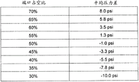
图5示出根据一个实施例的用于将端口占空比与平均压力差相关联的查询表的实施例;和5 illustrates an embodiment of a look-up table for associating port duty cycles with average differential pressures, according to one embodiment; and
图6示出具有包括两个或更多个阀的气动阀的一个实施例。Figure 6 shows an embodiment with a pneumatic valve comprising two or more valves.
应可理解,前述一般描述和下面的详细描述都仅为示例性和说明性的,并且旨在提供如权利要求限定的本发明的进一步的说明。It is to be understood that both the foregoing general description and the following detailed description are exemplary and explanatory only and are intended to provide further explanation of the invention as claimed.
具体实施方式 Detailed ways
Denis Turner,Robert Palino,Argelio Olivera和Mark Hopkins于2006年12月21日提交的名称为“Pneumatic System for aVitrector”,公开号No.20080149197,序列号No.11/614,678的美国专利申请公开文献以引用的方式以其全文并入本文,如同在本文中全面并且完全提出一样。U.S. Patent Application Publication No. 20080149197, Serial No. 11/614,678, filed Dec. 21, 2006, by Denis Turner, Robert Palino, Argelio Olivera, and Mark Hopkins, entitled "Pneumatic System for a Vitrector", is cited by reference is incorporated herein in its entirety in its entirety as if fully and fully set forth herein.
图1示出用于气动驱动眼科手术机器的手术控制台101的实施例。手术控制台101可构造成驱动一个或多个气动工具103。工具103可包括例如剪刀、玻璃体切除仪、钳子和注射或提取模块。也可使用其他工具103。在操作中,图1的气动驱动的眼科手术机器可在进行各种眼科手术过程例如玻璃体切除术中进行操作来辅助外科医生。例如氮气等压缩气体可通过手术控制器101提供动力来驱动工具103。手术控制台101可包括用于向用户显示信息的显示器109(显示器也可结合用于接收用户输入的触摸屏)。手术控制台101也可包括流动控制模块105(例如用于支持灌注/抽吸功能)和用于连接到工具103的一个或多个端口连接器107(例如通过附接到工具103的气动管来连接)。Figure 1 shows an embodiment of a
图2是根据一个实施例的用于气动驱动的玻璃体切除机器的气动系统的示意图。如图2中所示,气动系统可包括一个或多个气动阀217,用于将压力源209(例如调压源,如气缸或壁出口空气供给源)连接到输出端口A 213和输出端口B 215(出口端口A 213和出口端口B 215可通过一个或多个端口连接器107连接到工具103)。在一些实施例中,气动阀217可通过控制器205控制。在一些实施例中,压力源209的压力也可通过控制器205或(例如位于手术控制台101内部的)单独的控制器管控。控制器205可管控压力(例如在用于减小空气消耗的较低压力和用于加快切割速率和/或增大可用切割速率的动态范围的较高压力之间平衡)。在一些实施例中,气动系统的部件可结合在歧管中(例如由例如铝等金属机加工出来的歧管)。歧管可以是气密的,并且包括各种配件和接头,并且能够承受相对高的气体压力。多个歧管可以作为独立的部件制造,或其可以制造成一体式部件。在各个实施例中,(例如歧管中的)气动系统的部件可结合在手术控制台101内部。2 is a schematic diagram of a pneumatic system for a pneumatically driven vitrectomy machine, according to one embodiment. As shown in FIG. 2, the pneumatic system may include one or more
在一些实施例中,气动阀217可以是四通阀。还可考虑其他阀结构。阀217可包括螺线管,其根据来自控制器205的控制信号的指令操作以将阀217移动到两个位置中的一个(例如,参见图2a-b)。在第一位置,气动阀217可使加压气体通过气动阀217到达出口端口B215,以向探针切割件225提供气动动力,同时将加压气体通过消音器227从出口端口A 213排出。在第二位置,阀217可将加压气体提供到出口端口A 213,并且将加压气体从出口端口B 215排出。在该位置,加压气体可通过出口端口A 213,以将气动动力提供给工具103(例如探针切割件225)。因而,当气动阀217处于第一位置时,双隔室223的第一隔室229可充气,同时第二隔室231可排气。当气动阀217处于第二位置时,第二隔室231可充气,同时第一隔室229可排气。In some embodiments,
如图3中所示,探针切割件225可用作切割装置。探针切割件225可在具有切割件端口301的外管303内部往复移动(例如,探针切割件225可通过隔膜221移动,所述隔膜221则在加压气体交替地导向出口端口A和B(并且进入双隔室223的相应的隔室中)时振荡)。在一些实施例中,探针切割件225可通过管219附接到出口端口A和B(也可针对每一个端口使用单独的管)。当探针切割件225往复移动时,探针切割件225可借助探针切割件225的尖锐末端交替打开和闭合切割件端口301。探针切割件225通过外管303的每一次循环可在探针切割件225闭合时切穿切割件端口301中的例如玻璃体等材料。端口占空比(PDC)可表示切割件端口301打开和闭合的时间量。例如,49%的PDC可表示切割件端口301处于打开的时间为循环时间的49%(并且处于闭合的时间为循环时间的51%——循环时间为例如切割件端口301的各次连续打开之间的时间量)。As shown in FIG. 3,
在一些实施例中,阀占空比(VDC,valve duty cycle)可包括气动阀217处于第一和第二位置的时间量。在一些实施例中,探针切割件225的切割速率可通过控制器205经由阀217控制。例如,为了提供每分钟2500次切割的探针速率,控制器205可控制气动阀217将加压空气以每次循环约24ms的速率交替提供到端口A(第二通道)和端口B(第一通道)。为了获得每分钟2500次切割的切割速率,两个气动通道可每24ms进行一次打开/闭合循环(2500次切割/分钟或1分钟/2500次切割×60秒/1分=0.024秒/次切割=24ms/次切割),这对于每一个通道可以持续打开12ms。在一些实施例中,实际打开和闭合通道的过渡时间可占用部分循环时间。例如,对于每次循环24ms的6ms总过渡时间来说,气动第二通道(即经气动阀217的端口A 213)可用4ms来打开(同时气动第一通道闭合),用2ms来闭合(同时气动第一通道打开)。其他过渡时间也可考虑。由于过渡时间,因此阀可实际上针对第二通道仅打开8ms(12ms-4ms),同时针对第一通道闭合;并且可以针对第二通道闭合10ms(12ms-2ms),同时针对第一通道打开。该阀在向第二通道和第一通道提供加压空气时的8ms与10ms的这种时间差可导致两个通道中不平衡的压力差。在一些实施例中,可能期望两个通道的打开持续时间基本相同(例如,在2500次切割/分钟的情况下,实际打开约(24ms-6ms)/2=9ms)。In some embodiments, valve duty cycle (VDC) may include the amount of time the
如果打开/闭合过渡时间对于所有气动阀217都是恒定的,则控制器205可基于标准气动阀217以固定阀占空比进行预编程,以对于两个通道获得约相等的实际打开持续时间。例如,对于第二通道,标称打开时间可设置为13ms,对于第一通道可设置为11ms。因而,对于该示例,除去过渡时间,第二通道的实际打开时间可以是13ms-4ms=9ms,第一通道的实际打开时间可以是11ms-2ms=9ms(类似于第二通道)。但是,由于不同的气动阀217彼此之间的过渡时间可能不同(例如,由于气动阀217的制造差异、气流阻力、温度、老化等因素造成),因此固定的阀占空比可能不能成功地抵消该不平衡。例如,不同的阀可能要用3ms(而不是4ms)来打开第二通道(同时气动第一通道闭合),并且用2ms闭合第二通道(同时气动第一通道打开)。如果相同的阀占空比(例如第二通道标称打开时间为13ms,第一通道标称打开时间为11ms)应用到该第二阀示例,则对于第二阀的气动第二通道,实际打开时间将为13ms-3ms=10ms,对于第一通道,实际打开时间将为11ms-2ms=9ms。因此,针对前面阀示例起作用的阀占空比导致气动第二通道比用于第二示例阀的气动第一通道实际上多保持打开1ms或长11%。这种差异可能导致两个气动通道之间不均匀的动力平衡,这可能导致较不期望的性能。类似地,固定的阀占空比可能无法成功地抵消不同控制台的由于两个通道中流动限制/阻力差异而造成的不平衡。If the open/close transition time is constant for all
在一些实施例中,阀差异的效果可以通过监测阀217出口处的压力波形(例如,在阀运行过程中由压力传感器211(图2a)检测的或通过控制器使用来自压力传感器212a,b(图2b)的压力信息计算得到的平均压力差207)来动态补偿。压力信息可包括例如在压力传感器212a,b处检测到的压力波形或来自压力传感器212a,b的平均压力读数(其他压力信息也是可以的)。压力传感器211,212a,b可包括能够读取压缩气体压力并将包含关于压缩气体压力信息的电信号传送到控制器205的压力换能器(pressure transducer)。可在运行期间监测(例如周期性地或者连续地监测)压力波形(其可以表示实际VDC)。平均压力差207可由控制器205使用,以通过修改阀的VDC来补偿阀的变化,从而减小实际压力差和期望压力差之间的差异。因而,在一些实施例中,闭环控制法可包括监测气动阀217的输出端处的平均压力差(端口A 213和端口B 215之间的压力差),以及使用所述平均压力差207来确定用于控制VDC的阀的特定信息。在一些实施例中,在循环周期(1/cutrate)上的平均压力差207可直接与VDC相关,并且可被控制器205使用来动态调整发送到气动阀217的控制信号的VDC。在一些实施例中,实际压力差可能不能计算,但是相反,控制器可比较来自传感器212a,b的压力信息,以动态调整VDC。例如,来自端口A和端口B的压力波形(或平均压力)的比较结果可表示能够通过调整VDC抵消的差值。其他VDC调整也是可能的。In some embodiments, the effect of the valve differential can be monitored by monitoring the pressure waveform at the outlet of valve 217 (eg, detected by pressure sensor 211 (FIG. 2a) during valve operation or by the controller using input from
首先,在阀操作之前,可基于用户输入(例如通过手术控制台的用户接口接收到的)或手术控制台101上的存储器中存储的系统默认值来确定期望的压力差(端口A和端口B之间的)。在阀操作过程中,控制器205可基于检测/计算的实际的压力差来修改阀217的阀占空比。例如,压力传感器211可检测端口A 213和端口B 215之间的压力差,并且将表示压力差的信号发送到控制器205。在一些实施例中,压力传感器211可基于检测的压力差波形来计算平均压力差207,或压力传感器211可将检测到的压力差波形分程传递给(relay)控制器205,并且控制器205可确定平均压力差207。在一些实施例中,平均压力差207可作为控制器205能够解释的信号被发送到控制器205,以推导出压力(或例如,用于推导出与压力相关的其他值)。虽然图2a中显示了一个压力传感器211,但是在一些实施例中(例如,如图2b中所示),端口A 213和端口B 215中的每一个可具有可与控制器205通讯的单独的压力传感器(压力传感器212a,b)。在一些实施例中,控制器可从压力传感器212a,b接收压力信息,计算两个端口之间的压差波形,然后由压差波形确定平均压力差。作为另一个示例,控制器可确定用于控制阀217的阀占空比的每一个压力传感器输出波形的偏移值(例如,控制器可比较来自压力传感器212a,b的压力信息,以确定两个端口压力之间的平均差值)。这些压力差/平均压力差可用于确定该怎样动态调整VDC。First, prior to valve operation, the desired differential pressure (port A and port B between). During valve operation,
在一些实施例中,控制器205可确定时间间隔(对应于修改的阀占空比),以向阀217发出处于第一位置和第二位置的信号,从而获得端口A和端口B之间的期望的平均压力差。通过将调整的阀占空比应用到气动通道的循环时间,气动通道可在总循环时间过程中致动特定的实际打开时间。如上面所说明的,50%的阀占空比可对应于施加信号(即给阀提供动力使其进入第一位置)和不施加信号(即不给阀提供动力从而使其进入第二位置)的时间基本相同。1%的调整可导致51%的占空比,其对应于如下情形,即:施加信号来向阀提供动力的时间约为总循环时间的51%(并且总循环时间的49%不施加信号(从而将阀设置到第二位置))。较长的51%的占空比可因而补偿例如相比于其移动到第二位置要使用更长的时间来移动到第一位置的阀,或补偿在连接到阀的第一位置的通道中具有较高流动限制/阻力的控制台。在一些实施例中,阀占空比也可针对不同的控制台特性进行调整(例如,用于补偿各种阀的不同过渡时间和各种控制台的流动限制/阻力变化)。In some embodiments, the
在各个实施例中,控制器205可构造成通过电子接口(例如电导体,如金属线、总线、电路板走线等)接收信号。控制器205也可构造成通过电子接口将输出信号发送到气动阀217。这些输出信号可使控制器205控制气动阀217的操作。控制器205可包括能够执行逻辑功能的集成电路。以该方式,控制器205可以是具有电源引脚、输入引脚和输出引脚的标准集成电路封装件的形式。在各个实施例中,控制器205可包括阀控制器或目标装置控制器。在一些实施例中,控制器205可执行以特定装置例如阀等为目标的专用控制功能。在一些实施例中,控制器205可以是微处理器。在这样的情况下,控制器205可以是可编程的,以使其可用于控制阀以及控制台101的其他部件。在一些实施例中,控制器205不是可编程微处理器,而是构造成控制执行不同功能的不同阀的专用控制器。In various embodiments, the
图4示出用于动态控制气动阀217的方法的一个实施例的流程图。提供在流程图中的要素仅为示例性的。各个提供的要素可省略,可添加附加的要素和/或各个要素可以与下面提供的次序不同的次序执行。FIG. 4 shows a flowchart of one embodiment of a method for dynamically controlling the
在401处,用户可选择期望的切割速率和/或PDC(例如根据手术需要而进行选择)。例如,用户可在50%的PDC下输入2500次切割每分钟的切割速率。At 401 , a user may select a desired cut rate and/or PDC (eg, based on surgical needs). For example, the user may enter a cut rate of 2500 cuts per minute at a PDC of 50%.
在403处,期望的PDC可转换为期望的平均压力差(或与端口A和B之间的压力差相关的其他压力差/度量值)。在一些实施例中,期望的PDC可根据预先建立的查询表(例如,参见图5)、公式等转换为期望的平均压力差。在一些实施例中,用户可将期望的平均压力差输入显示器103上的接口中。在一些实施例中,PDC和期望的平均压力差可以默认值提供(例如,50%PDC,0psi(磅每平方英寸)的期望平均压力差)。平均压力差可指端口A和端口B之间的压力差的平均值(作为端口A和端口B之间的压力差波形的在时间上的平均值)或端口A的平均压力和端口B的平均压力之间的差值。例如,用于阀的PDC和相应的平均压力差可实验性地通过试验和误差等确定。在一些实施例中,可使用其他特性来确定期望的平均压力差(例如附接的工具类型等)。At 403 , the desired PDC may be converted to a desired average pressure difference (or other pressure difference/measure related to the pressure difference between ports A and B). In some embodiments, the desired PDC may be converted to a desired average pressure difference according to a pre-established look-up table (eg, see FIG. 5 ), formula, or the like. In some embodiments, a user may enter a desired average pressure difference into an interface on display 103 . In some embodiments, the PDC and desired mean differential pressure may be provided as default values (eg, 50% PDC, 0 psi (pounds per square inch) desired mean differential pressure). Mean differential pressure can refer to the average of the pressure differential between port A and port B (as the average over time of the pressure differential waveform between port A and port B) or the average pressure of port A and the average of port B pressure difference. For example, the PDC for a valve and the corresponding average differential pressure can be determined experimentally by trial and error, etc. FIG. In some embodiments, other characteristics may be used to determine the desired average pressure differential (eg, type of tool attached, etc.).
在405处,气动阀217可通过控制器205控制来操作工具103。在一些实施例中,控制器205可首先使用默认阀占空比(例如50%)控制阀217。在一些实施例中,控制器205可从偏差转换器(offsettranslator)203(例如,构造成基于内部查询表(例如,参见图5)将接收的表示期望PDC 201的电信号转换为相应的期望平均压力差)接收期望的平均压力差。在一些实施例中,除了或代替期望的平均压力差,控制器205可接收其他期望性能特征(例如,控制器可接收端口A和端口B的平均压力波形之间的期望差值,或可根据端口A和端口B的期望平均压力来接收端口A压力和端口B压力的期望偏差)。At 405 ,
在407处,平均压力差207可从压力传感器211分程传送到控制器205(或使用来自压力传感器212a,b的压力信息通过控制器205计算该平均压力差)。例如,平均压力差207可由压力传感器200每100毫秒分程传送(或者压力信息(例如压力偏差)可由压力传感器212a,b分程传送,并且平均压力差207可由控制器205计算)。其他时间间隔也可考虑(例如每5秒)。在一些实施例中,压力传感器211可根据检测的压力差波形计算平均压力差,或压力传感器211可将检测到的压力差波形(其可包括端口A和端口B之间的一个或多个压力差)分程传送到控制器205,并且控制器205可确定平均压力差207。在一些实施例中,连接到端口A和B的压力传感器212a,b可将检测到的压力信息(例如压力偏差、压力波形等)分程传送给控制器205,并且控制器205可确定端口的平均压力差(或可比较压力波形而不实际计算平均压力差)。At 407, the average
在409处,控制器205可比较测量的平均压力差207(例如从压力传感器接收的或使用来自压力传感器的信息计算得到的)与期望的平均压力差(例如根据接收自用户的信息或默认设置而计算得到/确定的),并且确定修改的VDC。控制器205可确定修改的VDC来减小期望的平均压力差和测量的平均压力差之间的差值。例如,如果端口A处的压力视为正压力,端口B处的压力视为负压力,则对于理想的阀来说,测量的平均压力差可以是0psi。相反,若在该示例中测量的平均压力差是正的(例如+2psi),则测量的平均压力差可表明:在指定循环中,端口A保持打开的时间比端口B更长(导致端口A在打开时充气到的压力要比端口B在打开时充气到的压力更高)。如果期望的平均压力差设置为0psi,则VDC(其可表示控制器205向端口A发出排气信号的时间百分比)可由控制器增大(例如从50%到51%)。在一些实施例中,控制器205可根据默认值或用户提供的比率增大或减小VDC。在一些实施例中,对于阀217而言,响应于期望的平均压力差和测量的压力差之间的差值而调整VDC的量可通过实验确定。例如,通过实验可能确定,对于测量的平均压力差和期望的平均压力差之间每+1.2pis的差而言要增大1%的VDC(其他比率也可考虑)。该信息可以控制器205能够访问的公式或表格的形式存储。作为另一个示例,如果平均压力差为正,则控制器205可以用户提供的增量(例如0.5%)增大VDC;如果平均压力差为负,则控制器205可以用户提供的增量减小VDC。在一些实施例中,如果测量的平均压力差在默认的或用户提供的范围内,则控制器205可不调整VDC(例如,如果平均压力差在1psi的期望平均压力差范围内,则不调整)。在一些实施例中,用户可输入供控制器使用的各种输入(例如输入显示器109的触摸屏)。例如,对于测量的平均压力差和期望的平均压力差之间每+1.2psi的压力差,用户可输入-1%比率的VDC。在一些实施例中,控制器可不实际计算压力差,而是可将来自端口A和端口B的压力波形(例如,如由压力传感器212a,b确定的)彼此比较,或与期望的波形比较,以确定怎样调整VDC。例如,如果用于端口A的压力波形平均比期望压力波形(例如存储在系统上的)大2psi,则可调整VDC而不必实际计算压力差。也可考虑其他VDC调整技术。At 409, the
在411处,控制器205可在向气动阀217提供动力时使用修改的VDC(例如,来控制在第一/第二位置之间切换的时间)。At 411 , the
在413处,控制器205可在比较测量的压力差207和期望的平均压力差(或与压力差相关的变量/度量)与确定新的修改的VDC之间迭代,以最小化测量的平均压力差207和期望的平均压力差之间的差值。例如,控制器205可执行PID控制器算法(比例积分微分),以增大或减小地调整占空比,接收新的检测的平均压力差(或接收新的压力信息来用于计算平均压力差),根据与之前的平均压力差相比较的新平均压力差的方向相应地增大或减小地调整阀VDC,响应于修改的阀占空比等接收/计算新的平均压力差,直到平均压力差和期望的压力差之间的差值减小(例如落入用户提供的范围内)。At 413, the
在一些实施例中,该气动管理系统可包括一个或多个处理器。所述处理器可包括单个处理装置或多个处理装置。这样的处理装置可以是微处理器、控制器(例如控制器205)(其可以是微控制器)、数字信号处理器、微计算机、中央处理单元、场可编程门阵列、可编程逻辑装置、状态机、逻辑电路、控制电路、模拟电路、数字电路和/或根据操作指令操纵信号(模拟和/或数字)的任何装置。连接到和/或嵌入处理器中的存储器可以是单个存储装置或多个存储装置。这样的存储装置可以是只读存储器、随机存取存储器、易失性存储器、非易失性存储器、静态存储器、动态存储器、闪存、缓存和/或存储数字信息的任何装置。应注意的是,当处理器通过状态机、模拟电路、数字电路和/或逻辑电路执行其功能中的一个或多个时,存储相应操作指令的存储器可嵌入构成状态机、模拟电路、数字电路和/或逻辑电路的电路中,或处于所述电路外部。存储器可存储、且处理器可执行对应于在结合附图示出和描述的元件中的至少一些的操作指令。In some embodiments, the pneumatic management system may include one or more processors. The processor may comprise a single processing device or a plurality of processing devices. Such a processing device may be a microprocessor, a controller (such as controller 205) (which may be a microcontroller), a digital signal processor, a microcomputer, a central processing unit, a field programmable gate array, a programmable logic device, A state machine, logic circuit, control circuit, analog circuit, digital circuit, and/or any device that manipulates signals (analog and/or digital) in response to operational instructions. The memory connected to and/or embedded in the processor may be a single memory device or multiple memory devices. Such a storage device may be a read-only memory, random access memory, volatile memory, non-volatile memory, static memory, dynamic memory, flash memory, cache memory, and/or any device that stores digital information. It should be noted that when the processor performs one or more of its functions through a state machine, an analog circuit, a digital circuit and/or a logic circuit, a memory storing corresponding operation instructions may be embedded to form a state machine, an analog circuit, a digital circuit and/or logic circuits, or external to said circuits. The memory can store, and the processor can execute, operating instructions corresponding to at least some of the elements shown and described in connection with the figures.
如图6中所示,尽管在本文中是结合四通气动阀来描述这几个实施例,但是应可理解,这些实施例同样适用于以协同方式被控制、以向工具103提供加压气体的两个或更多个阀。例如,结合四通气动阀描述的“第一端口”和“第二端口”可以可替代地连接到两个或更多个单独的阀(即,“第一端口”连接到第一阀,“第二端口”连接到第二阀)。可对第一阀和第二阀一起进行控制来交替地向第一端口和第二端口提供加压气体。在一些实施例中,压力传感器可同时连接到第一和第二端口来确定压力差(或每一个端口可连接到单独的压力传感器,并且可使用单独的压力传感器来确定平均压力)。这样,可相对于两个或更多个阀来使用阀占空比,以调节通道的相应端口的打开和闭合时间(通过根据由阀占空比表示的打开/闭合时间来控制单独的阀)。As shown in FIG. 6, although several embodiments are described herein in connection with four-way pneumatic valves, it should be understood that the embodiments are equally applicable to being controlled in a coordinated manner to provide pressurized gas to tool 103. two or more valves. For example, a "first port" and a "second port" described in connection with a four-way pneumatic valve may alternatively be connected to two or more separate valves (ie, "first port" is connected to a first valve, " Second port" is connected to the second valve). The first valve and the second valve may be controlled together to alternately provide pressurized gas to the first port and the second port. In some embodiments, a pressure sensor may be connected to both the first and second ports to determine the differential pressure (or each port may be connected to a separate pressure sensor and the separate pressure sensor may be used to determine the average pressure). In this way, the valve duty cycle can be used with respect to two or more valves to adjust the opening and closing times of the corresponding ports of the channel (by controlling the individual valves according to the opening/closing time represented by the valve duty cycle) .
本领域普通技术人员可对提出的实施例作出各种修改。通过考虑本发明的说明书和本文公开的本发明的实施,本发明的其他实施例对于本领域技术人员将显而易见。本说明书和示例应当仅视为示例性的,具有由下面权利要求及其等同形式表明的本发明真正范围和精神。Various modifications to the presented embodiments may be made by those of ordinary skill in the art. Other embodiments of the invention will be apparent to those skilled in the art from consideration of the specification and practice of the invention disclosed herein. The specification and examples should be considered illustrative only, with a true scope and spirit of the invention as indicated by the following claims and their equivalents.
Claims (19)
Applications Claiming Priority (3)
| Application Number | Priority Date | Filing Date | Title |
|---|---|---|---|
| US28524309P | 2009-12-10 | 2009-12-10 | |
| US61/285,243 | 2009-12-10 | ||
| PCT/US2010/056305 WO2011071655A1 (en) | 2009-12-10 | 2010-11-11 | Systems and methods for dynamic pneumatic valve driver |
Publications (2)
| Publication Number | Publication Date |
|---|---|
| CN102652006A CN102652006A (en) | 2012-08-29 |
| CN102652006B true CN102652006B (en) | 2014-06-11 |
Family
ID=43530666
Family Applications (1)
| Application Number | Title | Priority Date | Filing Date |
|---|---|---|---|
| CN201080055636.6A Active CN102652006B (en) | 2009-12-10 | 2010-11-11 | Systems and methods for dynamic pneumatic valve driver |
Country Status (10)
| Country | Link |
|---|---|
| US (1) | US8728108B2 (en) |
| EP (1) | EP2509549B1 (en) |
| JP (1) | JP5711259B2 (en) |
| CN (1) | CN102652006B (en) |
| AU (1) | AU2010328590B2 (en) |
| BR (1) | BR112012013974B1 (en) |
| CA (1) | CA2781157C (en) |
| ES (1) | ES2442368T3 (en) |
| RU (1) | RU2556529C2 (en) |
| WO (1) | WO2011071655A1 (en) |
Families Citing this family (37)
| Publication number | Priority date | Publication date | Assignee | Title |
|---|---|---|---|---|
| US8568391B2 (en) | 2007-04-20 | 2013-10-29 | Doheny Eye Institute | Sterile surgical tray |
| EP3150180B1 (en) | 2007-04-20 | 2019-06-12 | Doheny Eye Institute | Independent surgical center |
| JP5770731B2 (en) | 2009-08-31 | 2015-08-26 | アルコン リサーチ, リミテッド | Control of pneumatic output by drive valve duty |
| CN102652006B (en) | 2009-12-10 | 2014-06-11 | 爱尔康研究有限公司 | Systems and methods for dynamic pneumatic valve driver |
| US8821524B2 (en) | 2010-05-27 | 2014-09-02 | Alcon Research, Ltd. | Feedback control of on/off pneumatic actuators |
| US8808318B2 (en) | 2011-02-28 | 2014-08-19 | Alcon Research, Ltd. | Surgical probe with increased fluid flow |
| US8496681B2 (en) | 2011-06-06 | 2013-07-30 | Synergetics, Inc. | Systems and methods for vitrectomy |
| US8924028B2 (en) * | 2011-08-01 | 2014-12-30 | Control Microsystems, Inc. | Battery-powered control valve and operation thereof |
| US8973595B2 (en) | 2011-08-01 | 2015-03-10 | Control Microsystems, Inc. | Battery-powered control valve and operation thereof |
| CN103890468B (en) * | 2011-08-01 | 2015-11-25 | 康特罗尔微系统公司 | Battery powered control valve and method of operation thereof |
| US9060841B2 (en) | 2011-08-31 | 2015-06-23 | Alcon Research, Ltd. | Enhanced flow vitrectomy probe |
| US10070990B2 (en) | 2011-12-08 | 2018-09-11 | Alcon Research, Ltd. | Optimized pneumatic drive lines |
| US9629748B2 (en) | 2012-05-31 | 2017-04-25 | Medical Instrument Development Laboratories, Inc. | Multi-stage tubing for high-speed pneumatic surgical cutter |
| WO2013180718A1 (en) * | 2012-05-31 | 2013-12-05 | Medical Instrument Development Laboratories, Inc. | Multi-stage tubing for high-speed pneumatic surgical cutter |
| US9924963B2 (en) * | 2012-12-13 | 2018-03-27 | Novartis Ag | Vitrectomy probe with integral valve |
| US9271867B2 (en) * | 2012-12-17 | 2016-03-01 | Abbott Medical Optics Inc. | Vitrectomy surgical apparatus with regulating of material processed |
| US9498376B2 (en) | 2012-12-17 | 2016-11-22 | Abbott Medical Optics Inc. | Vitrectomy surgical apparatus with cut timing based on pressures encountered |
| US9486358B2 (en) * | 2012-12-17 | 2016-11-08 | Abbott Medical Optics Inc. | Vitrectomy surgical apparatus |
| US9615969B2 (en) | 2012-12-18 | 2017-04-11 | Novartis Ag | Multi-port vitrectomy probe with dual cutting edges |
| ITTO20130746A1 (en) * | 2013-09-13 | 2015-03-14 | Sinterleghe S R L | POWER SUPPLY DEVICE FOR ELECTRODE CAPS. |
| EP3134044B1 (en) | 2014-04-23 | 2018-10-03 | Johnson & Johnson Surgical Vision, Inc. | Vitrectomy surgical apparatus employing multisensor pressure feedback |
| FR3022606B1 (en) * | 2014-06-19 | 2016-06-24 | Continental Automotive France | METHOD FOR DETERMINING THE POINT OF OPENING A VALVE |
| US9693898B2 (en) | 2014-11-19 | 2017-07-04 | Novartis Ag | Double-acting vitreous probe with contoured port |
| AU2016247673B2 (en) * | 2015-04-13 | 2020-07-16 | Alcon Inc. | High speed pneumatic valve |
| US10458444B2 (en) * | 2017-09-28 | 2019-10-29 | Fisher Controls International Llc | Optimized method for controlling position and crossover pressure in a double acting actuator |
| US11540942B2 (en) | 2018-07-26 | 2023-01-03 | Alcon Inc. | Redundant pneumatic circuit for reliability enhancement of vitrectomy instruments |
| US10746314B2 (en) * | 2018-09-14 | 2020-08-18 | Fisher Controls International Llc | Positioner apparatus for use with fluid valves |
| NL2022011B1 (en) * | 2018-11-16 | 2020-05-26 | Crea Ip B V | Vitrectome actuator |
| US11642243B2 (en) | 2018-12-10 | 2023-05-09 | Alcon Inc. | Methods of solenoid valve control optimization |
| WO2020217127A1 (en) * | 2019-04-24 | 2020-10-29 | Alcon Inc. | Valve cooling and noise suppression |
| KR20220093099A (en) | 2019-10-30 | 2022-07-05 | 알콘 인코포레이티드 | dual port pneumatic connector |
| US11934209B2 (en) * | 2020-09-14 | 2024-03-19 | Alcon Inc. | Methods and systems for providing control stability in a vacuum generation system using an override proportional-integral-derivative (PID) controller |
| US11865040B2 (en) * | 2021-05-10 | 2024-01-09 | Bausch + Lomb Ireland Limited | Vitrectomy cutter |
| CN113374921B (en) * | 2021-08-11 | 2021-10-29 | 山东柏源技术有限公司 | Converter control system for oilfield pipeline fluid pressure |
| DE102022112103B4 (en) * | 2022-05-13 | 2024-01-04 | Carl Zeiss Meditec Ag | Console of an ophthalmic surgical system and ophthalmic surgical system for treating an eye |
| WO2024027902A1 (en) * | 2022-08-02 | 2024-02-08 | Bausch + Lomb Ireland Limited | Vitrectomy cutter |
| CN116301086B (en) * | 2023-05-16 | 2023-09-05 | 图湃(北京)医疗科技有限公司 | Vitrectomy machine, monitoring method and device for vitrectomy machine |
Citations (2)
| Publication number | Priority date | Publication date | Assignee | Title |
|---|---|---|---|---|
| US5549139A (en) * | 1989-10-27 | 1996-08-27 | Storz Instrument Company | Pneumatic controls for ophthalmic surgical system |
| CN101568306A (en) * | 2006-12-22 | 2009-10-28 | 爱尔康研究有限公司 | Method of operating microsurgical instrument |
Family Cites Families (170)
| Publication number | Priority date | Publication date | Assignee | Title |
|---|---|---|---|---|
| US812162A (en) | 1905-12-18 | 1906-02-06 | Thomas Bemis | Pneumatic tube for store service. |
| US2016746A (en) | 1933-08-25 | 1935-10-08 | Thomas H Ireland | Fluid heater |
| NL73735C (en) | 1949-06-30 | |||
| GB792397A (en) | 1956-05-09 | 1958-03-26 | Pneumatic Components Ltd | Improvements in or relating to tyre inflation hose equipment |
| US3084674A (en) | 1961-07-20 | 1963-04-09 | Ingersoll Rand Co | Pneumatic system for multiple nut runner |
| US3601588A (en) | 1966-05-23 | 1971-08-24 | Foxboro Co | Method and apparatus for adaptive control |
| FR1506385A (en) * | 1966-09-16 | 1967-12-22 | Sud Aviation | Method of attenuation and electro-hydraulic vibration attenuator for rotary wing aerodyne |
| US3515155A (en) | 1967-02-24 | 1970-06-02 | Air Reduction | Gas mixture proportioner |
| US3646727A (en) | 1969-06-02 | 1972-03-07 | Erich A Wachsmuth | Automatic compressor drain system |
| GB1281196A (en) | 1969-11-20 | 1972-07-12 | Westland Aircraft Ltd | Improvements in or relating to pressure control systems |
| FR2117726B1 (en) | 1970-12-10 | 1973-12-07 | Aquitaine Petrole | |
| US3815604A (en) * | 1972-06-19 | 1974-06-11 | Malley C O | Apparatus for intraocular surgery |
| US3867934A (en) | 1973-05-04 | 1975-02-25 | Veriflo Corp | Pressure monitor for a lung ventilator |
| US3854382A (en) * | 1973-06-20 | 1974-12-17 | Sperry Rand Ltd | Hydraulic actuator controls |
| GB1417299A (en) | 1973-09-18 | 1975-12-10 | Gulde Regelarmatuhren Kg | Method and apparatus for safe-guarding pipe-lines against inadmissibly high internal pressure by a control valve with a pneumatic drive |
| US4011869A (en) * | 1975-08-01 | 1977-03-15 | David Kopf Instruments | Tubular cutting instrument |
| GB1518720A (en) * | 1975-11-21 | 1978-07-26 | Ishikawajima Harima Heavy Ind | Hydraulic servomechanism |
| US4077567A (en) | 1976-06-18 | 1978-03-07 | Universal Pneumatic Controls, Inc. | Pneumatic temperature reset differential pressure controller |
| US4086804A (en) | 1976-10-26 | 1978-05-02 | Sperry Rand Corporation | Precision pneumatic pressure supply system |
| US4323064A (en) | 1976-10-26 | 1982-04-06 | Puritan-Bennett Corporation | Volume ventilator |
| US4168707A (en) | 1977-06-13 | 1979-09-25 | Douvas Nicholas G | Control apparatus for microsurgical instruments |
| US4335867A (en) * | 1977-10-06 | 1982-06-22 | Bihlmaier John A | Pneumatic-hydraulic actuator system |
| US4368734A (en) * | 1978-01-27 | 1983-01-18 | Surgical Design Corp. | Surgical instrument |
| DE2811345C2 (en) | 1978-03-16 | 1986-12-11 | Knorr-Bremse AG, 8000 München | Pressure regulators for pneumatic pressures, in particular in vehicles |
| JPS5584858A (en) | 1978-12-18 | 1980-06-26 | Nippon Denso Co Ltd | Engine control |
| US4373549A (en) * | 1979-02-12 | 1983-02-15 | Hewlett-Packard Company | Mass flow/pressure control system |
| FR2455766B1 (en) | 1979-05-02 | 1985-09-06 | Intertechnique Sa | PNEUMATIC DEVICE AND INSTALLATION FOR CREATING PRESSURE OR FLOW CYCLES |
| US4331130A (en) | 1980-06-27 | 1982-05-25 | Lewicky Andrew O | Securing device to the cornea to prevent anterior chamber prolapse |
| US4590935A (en) | 1981-11-02 | 1986-05-27 | Optikon Oftalmologia, S.P.A. | Control system for intraocular surgical device |
| GB2140871A (en) | 1983-06-03 | 1984-12-05 | Bowthorpe Hellermann Ltd | Piston and cylinder actuator control |
| US4679583A (en) | 1984-04-19 | 1987-07-14 | Robertshaw Controls Company | Pneumatic control system, control means therefor and method of making the same |
| BR8403165A (en) | 1984-06-28 | 1984-11-27 | Jaime Roizenblatt | PNEUMATIC MODULE FOR INTRAOCULAR MICROSURGERY |
| US4678459A (en) * | 1984-07-23 | 1987-07-07 | E-Z-Em, Inc. | Irrigating, cutting and aspirating system for percutaneous surgery |
| US4706687A (en) | 1985-02-28 | 1987-11-17 | Alcon Instrumentation, Inc. | Linear suction control system |
| US4757814A (en) | 1985-02-28 | 1988-07-19 | Alcon Laboratories, Inc. | Proportional control for pneumatic cutting device |
| US4650462A (en) | 1985-07-29 | 1987-03-17 | Minnesota Mining And Manufacturing Company | Irrigation system |
| US4770654A (en) | 1985-09-26 | 1988-09-13 | Alcon Laboratories Inc. | Multimedia apparatus for driving powered surgical instruments |
| US4622503A (en) | 1985-09-26 | 1986-11-11 | Medical Instrument Development Laboratories, Inc. | Variable pneumatic output means for use with ophthalmic micro-surgical instruments |
| US4790816A (en) | 1985-09-26 | 1988-12-13 | Allon Laboratories, Inc. | Surgical cassette proximity sensing and latching apparatus |
| US4810242A (en) | 1985-09-26 | 1989-03-07 | Alcon Laboratories Inc. | Surgical cassette proximity sensing and latching apparatus |
| US4696298A (en) * | 1985-11-19 | 1987-09-29 | Storz Instrument Company | Vitrectomy cutting mechanism |
| US4840111A (en) | 1986-01-31 | 1989-06-20 | Moog Inc. | Energy-conserving regenerative-flow valves for hydraulic servomotors |
| US4933843A (en) | 1986-11-06 | 1990-06-12 | Storz Instrument Company | Control system for ophthalmic surgical instruments |
| WO1988006983A1 (en) * | 1987-03-18 | 1988-09-22 | Monroe Auto Equipment Company | Method and apparatus for absorbing mechanical shock |
| DE3708989C2 (en) | 1987-03-19 | 1993-10-14 | Festo Kg | Control device for a piston displaceable in a double-acting cylinder |
| US5239861A (en) | 1988-12-23 | 1993-08-31 | Kabushiki Kaisha Komatsu Seisakusho | Device for indicating contamination degree of hydraulic circuit and method of judging the contamination degree |
| US5092178A (en) * | 1989-04-28 | 1992-03-03 | Pneumo Abex Corporation | Differential pressure sensor mechanisms |
| US5019035A (en) * | 1989-06-07 | 1991-05-28 | Alcon Surgical, Inc. | Cutting assembly for surgical cutting instrument |
| US5106364A (en) * | 1989-07-07 | 1992-04-21 | Kabushiki Kaisha Topcon | Surgical cutter |
| DE3925405A1 (en) | 1989-08-01 | 1991-02-07 | Vdo Schindling | Pressure control unit esp. for vehicle windscreen wiper - has solenoid controlled relief valve to control pressure in load stage |
| US5020315A (en) * | 1989-08-08 | 1991-06-04 | United Technologies Corporation | Multiple function fuel valve and system |
| US5024654A (en) * | 1989-10-02 | 1991-06-18 | Alcon Surgical, Inc. | Insulated infusion and aspiration probe |
| US5176628A (en) | 1989-10-27 | 1993-01-05 | Alcon Surgical, Inc. | Vitreous cutter |
| US5047008A (en) * | 1989-10-27 | 1991-09-10 | Storz Instrument Company | Vitrectomy probe |
| US4985027A (en) * | 1990-02-26 | 1991-01-15 | Dressel Thomas D | Soft tissue aspiration device and method |
| US5138564A (en) * | 1990-07-31 | 1992-08-11 | Xerox Corporation | Automatic encoder calibration |
| US5094260A (en) | 1990-10-26 | 1992-03-10 | Alcon Surgical, Inc. | Proportional valve and pressure control system |
| AU2366092A (en) | 1991-07-31 | 1993-03-02 | Mentor O&O, Inc. | Controlling operation of handpieces during ophthalmic surgery |
| US5154207A (en) * | 1991-08-02 | 1992-10-13 | Mosier Industries, Inc. | Pressure control valve and transducer package |
| FI90035C (en) | 1992-02-07 | 1993-12-27 | Valmet Paper Machinery Inc | RULL STOPPING OCH FOERFARANDE FOER ANVAENDNING DAERAV |
| US5217465A (en) * | 1992-02-28 | 1993-06-08 | Alcon Surgical, Inc. | Flexible and steerable aspiration tip for microsurgery |
| DE4232586A1 (en) | 1992-09-23 | 1994-03-24 | Mannesmann Ag | Switching valve with regulation of output pressure - has inlet valve stage that closes when output pressure exceeds reference with vent valve stage opening to control pressure |
| DE4241846C2 (en) | 1992-12-11 | 1996-09-26 | Danfoss As | Hydraulic system |
| US5403276A (en) * | 1993-02-16 | 1995-04-04 | Danek Medical, Inc. | Apparatus for minimally invasive tissue removal |
| US5403280A (en) * | 1993-02-16 | 1995-04-04 | Wang; James C. | Inflatable perfusion catheter |
| DE4315626C1 (en) | 1993-05-11 | 1994-07-14 | Rexroth Mannesmann Gmbh | Control for a hydraulic drive |
| US5829335A (en) | 1993-05-11 | 1998-11-03 | Mannesmann Rexroth Gmbh | Control for hydraulic drive or actuator |
| JP2595450B2 (en) * | 1993-09-08 | 1997-04-02 | 日精樹脂工業株式会社 | Method and apparatus for detecting abnormality of hydraulic system in molding machine |
| US5550685A (en) * | 1993-10-22 | 1996-08-27 | Syquest Technology, Inc. | Applying an adaptive feed-forward algorithm as a frequency selective filter in a closed loop disk drive servo system in order to compensate for periodic perturbations which otherwise appear in the servo system position error signal |
| US5380280A (en) * | 1993-11-12 | 1995-01-10 | Peterson; Erik W. | Aspiration system having pressure-controlled and flow-controlled modes |
| US5457625A (en) * | 1994-04-13 | 1995-10-10 | The M. W. Kellogg Company | Maximizing process production rates using permanent constraints |
| US5487725A (en) | 1994-05-12 | 1996-01-30 | Syntec, Inc. | Pneumatic vitrectomy for retinal attachment |
| US5437241A (en) * | 1994-06-08 | 1995-08-01 | Pall Corporation | Differential pressure indicator |
| JP3679143B2 (en) * | 1994-06-30 | 2005-08-03 | 株式会社ニデック | Perfusion suction device |
| US5571248A (en) | 1995-03-10 | 1996-11-05 | General Motors Corporation | Pressure regulator |
| US5630827A (en) * | 1995-06-19 | 1997-05-20 | Dutch Ophthalmic Research Center International Bv | Vitreous removing apparatus |
| JPH0942210A (en) * | 1995-08-02 | 1997-02-10 | Ckd Corp | Cylinder drive controller |
| US5587536A (en) | 1995-08-17 | 1996-12-24 | Rasmussen; John | Differential pressure sensing device for pneumatic cylinders |
| US5674194A (en) | 1995-10-25 | 1997-10-07 | Alcon Laboratories Inc. | Process control system |
| US5989262A (en) * | 1996-04-15 | 1999-11-23 | Josephberg; Robert Gary | Sutureless pars plana vitrectomy tool |
| AU5690698A (en) * | 1996-11-27 | 1998-06-22 | Armand Maaskamp | Needle for surgical use |
| US5808396A (en) * | 1996-12-18 | 1998-09-15 | Alcon Laboratories, Inc. | System and method for tuning and controlling an ultrasonic handpiece |
| US5791142A (en) * | 1997-03-27 | 1998-08-11 | Husco International, Inc. | Hydraulic control valve system with split pressure compensator |
| SE9701523L (en) | 1997-04-23 | 1998-06-22 | Rudolf Westerberg Ab | Tvåhandsmanöversystem |
| JPH10339301A (en) | 1997-06-09 | 1998-12-22 | Smc Corp | Control method of automatically controlled pneumatic device and automatically controlled pneumatic device |
| US5846257A (en) | 1997-08-15 | 1998-12-08 | Nexus Medical System, Inc. Llc | Pressure sensor for a surgical system |
| US6425883B1 (en) * | 1998-05-08 | 2002-07-30 | Circuit Tree Medical, Inc. | Method and apparatus for controlling vacuum as a function of ultrasonic power in an ophthalmic phaco aspirator |
| DE19821420C1 (en) | 1998-05-13 | 1999-10-21 | Haldex Bremsen Gmbh & Co Kg | Pressurized air device for automobile pneumatic circuits |
| US6575264B2 (en) * | 1999-01-29 | 2003-06-10 | Dana Corporation | Precision electro-hydraulic actuator positioning system |
| WO2000078371A1 (en) | 1999-06-22 | 2000-12-28 | Scieran Technologies, Inc. | An apparatus and method for performing ophthalmic procedures |
| US6162187A (en) | 1999-08-02 | 2000-12-19 | Ethicon Endo-Surgery, Inc. | Fluid collection apparatus for a surgical device |
| US6514268B2 (en) * | 1999-08-30 | 2003-02-04 | Alcon Universal Ltd. | Method of operating microsurgical instruments |
| US6155233A (en) | 1999-09-07 | 2000-12-05 | Fasco Controls Corp. | Combination pressure sensor and regulator for direct injection diesel engine fuel system |
| US6575990B1 (en) * | 1999-10-21 | 2003-06-10 | Medical Instrument Development Laboratories, Inc. | High speed vitreous cutting system |
| NL1013376C2 (en) | 1999-10-22 | 2001-04-24 | Dutch Ophthalmic Res Ct B V | Surgical cutting tool. |
| AU2001245365B8 (en) * | 2000-02-29 | 2005-11-03 | Gen-Probe Incorporated | Fluid dispense and liquid surface verification system and method |
| US6443947B1 (en) | 2000-03-01 | 2002-09-03 | Alexei Marko | Device for thermal ablation of a cavity |
| US20010037689A1 (en) * | 2000-03-08 | 2001-11-08 | Krouth Terrance F. | Hydraulic actuator piston measurement apparatus and method |
| US6450966B1 (en) | 2000-05-03 | 2002-09-17 | Datex-Ohmeda, Inc. | Method for non-invasive blood pressure cuff identification using deflation pressure measurements |
| US6504474B1 (en) | 2000-07-12 | 2003-01-07 | Deere & Company | Method and apparatus for detecting a restricted or bypassed transmission oil filter |
| US6485436B1 (en) * | 2000-08-10 | 2002-11-26 | Csaba Truckai | Pressure-assisted biopsy needle apparatus and technique |
| US6561999B1 (en) | 2000-09-29 | 2003-05-13 | Alcon Universal Ltd. | Surgical cassette and consumables for combined ophthalmic surgical procedure |
| JP4021141B2 (en) * | 2000-10-20 | 2007-12-12 | 株式会社ニデック | Vitreous surgery device |
| US6758824B1 (en) * | 2000-11-06 | 2004-07-06 | Suros Surgical Systems, Inc. | Biopsy apparatus |
| US6471853B1 (en) | 2000-11-22 | 2002-10-29 | Pti Technologies, Inc. | Prognostic health monitoring of fluidic systems using MEMS technology |
| US6568416B2 (en) | 2001-02-28 | 2003-05-27 | Brian L. Andersen | Fluid flow control system, fluid delivery and control system for a fluid delivery line, and method for controlling pressure oscillations within fluid of a fluid delivery line |
| US6779541B2 (en) | 2001-10-12 | 2004-08-24 | Smc Kabushiki Kaisha | Fluid pressure regulator |
| US7470277B2 (en) | 2001-10-16 | 2008-12-30 | Alcon, Inc. | Simultaneous proportional control of surgical parameters in a microsurgical system |
| AU2002350396A1 (en) * | 2001-11-19 | 2003-06-10 | Luk Fahrzeug-Hydraulik Gmbh And Co. Kg | Determination of the piston stroke in a reciprocating piston machine |
| US6892745B2 (en) * | 2002-04-10 | 2005-05-17 | Honeywell International Inc. | Flow control valve with integral sensor and controller and related method |
| US6678584B2 (en) * | 2002-05-03 | 2004-01-13 | Fisher Controls International Llc | Method and apparatus for performing diagnostics in a control loop of a control valve |
| US6999853B2 (en) * | 2002-05-03 | 2006-02-14 | Fisher Controls International Llc. | Methods and apparatus for operating and performing diagnostics in a control loop of a control valve |
| US20030226809A1 (en) | 2002-06-06 | 2003-12-11 | Detroit Diesel Corporation | Method and apparatus for determining oil filter life |
| DE10247869B4 (en) | 2002-10-14 | 2007-02-08 | Imi Norgren Gmbh | Pressure medium actuated working cylinder |
| US8202277B2 (en) * | 2003-01-29 | 2012-06-19 | Edwin Ryan | Small gauge surgical instrument with support device |
| US20040186484A1 (en) * | 2003-01-29 | 2004-09-23 | Edwin Ryan | Small gauge surgical instrument with support device |
| US7219691B2 (en) * | 2003-02-07 | 2007-05-22 | Fisher Controls International Llc | Control valve positioner mounting system |
| DE10341477A1 (en) | 2003-09-05 | 2005-03-31 | Riehle, Rainer, Dipl.-Ing. | Sound generator for generating in pipelines of a water or gas supply system propagatable sound pulses |
| US20050245909A1 (en) * | 2004-04-29 | 2005-11-03 | Mccary Brian D | Embedded data chip in a surgical handpiece |
| US7775052B2 (en) * | 2004-05-07 | 2010-08-17 | Delavan Inc | Active combustion control system for gas turbine engines |
| US7337041B2 (en) * | 2004-06-14 | 2008-02-26 | Fisher Controls International | Feedback control methods and apparatus for electro-pneumatic control systems |
| US7283321B1 (en) * | 2004-10-08 | 2007-10-16 | Maxtor Corporation | Disk drives and methods allowing for dual stage actuator adaptive seek control and microactuator gain calibration |
| US7352287B2 (en) * | 2005-01-07 | 2008-04-01 | Veris Industries, Llc | Pneumatic controller |
| US20060271082A1 (en) | 2005-05-31 | 2006-11-30 | Kirchhevel G Lamar | Calibrated surgical probe |
| DE202005009670U1 (en) | 2005-06-17 | 2005-09-01 | Sieber, Dieter | Pneumatic drive muffler, has pressure sensor that produces warning signal and switches off pneumatic drive when impact pressure within cavity increased due to increased contamination of muffler reaches predetermined limit pressure |
| DE102005043367B4 (en) * | 2005-09-12 | 2016-09-08 | Laeis Gmbh | Control device and control method for a piston-cylinder arrangement |
| US7326183B2 (en) * | 2005-09-28 | 2008-02-05 | Alcon, Inc. | Intraocular pressure control |
| US7600405B2 (en) * | 2005-10-11 | 2009-10-13 | Alcon, Inc. | Microsurgical probe |
| EP1949042B1 (en) * | 2005-10-21 | 2015-11-11 | Lonza AG | Mass flow rate control system |
| WO2007062453A1 (en) * | 2005-11-30 | 2007-06-07 | Ulco Technologies Pty Ltd | Perfusion method and apparatus |
| US8187293B2 (en) * | 2006-02-06 | 2012-05-29 | Novartis Ag | Microsurgical instrument |
| US7774287B2 (en) * | 2006-03-14 | 2010-08-10 | Asml Netherlands B.V. | System and method for moving a component through a setpoint profile, lithographic apparatus and device manufacturing method |
| US20070270746A1 (en) | 2006-05-19 | 2007-11-22 | Alcon, Inc. | Surgical system having pneumatic manifolds with integral air cylinders |
| US9180232B2 (en) | 2006-05-19 | 2015-11-10 | Novartis Ag | Surgical system having manifolds with integral pneumatic accumulators |
| US20070282262A1 (en) | 2006-05-19 | 2007-12-06 | Alcon, Inc. | Surgical system having integral pneumatic manifolds |
| US20080125695A1 (en) | 2006-06-23 | 2008-05-29 | Hopkins Mark A | Reflux control in microsurgical system |
| DE102006030034A1 (en) | 2006-06-29 | 2008-01-03 | Zf Friedrichshafen Ag | Device for controlling a fluid-operated double-acting adjusting cylinder |
| US7708734B2 (en) * | 2006-06-30 | 2010-05-04 | Alcon, Inc. | Method for dynamically adjusting operation of a surgical handpiece |
| US7640119B2 (en) * | 2006-06-30 | 2009-12-29 | Alcon, Inc. | System for dynamically adjusting operation of a surgical handpiece |
| RU58919U1 (en) * | 2006-09-01 | 2006-12-10 | Ренат Сулейманович Акчурин | AUTONOMOUS COMPLEX FOR OPERATIONS ON THE OPEN WORKING HEART |
| FR2905594B1 (en) | 2006-09-08 | 2008-12-05 | Corneal Ind Soc Par Actions Si | PNEUMATIC VITREOTOME |
| US20080082077A1 (en) | 2006-09-29 | 2008-04-03 | David Lloyd Williams | System and method for flow rate control |
| US8679241B2 (en) | 2006-10-30 | 2014-03-25 | Novartis Ag | Gas pressure monitor for pneumatic surgical machine |
| US8038692B2 (en) * | 2006-10-31 | 2011-10-18 | Novartis Ag | Modular design for ophthalmic surgical probe |
| US8105405B2 (en) | 2006-11-07 | 2012-01-31 | Novartis Ag | Quick release filter assembly for pneumatic surgical machine |
| US7628054B2 (en) * | 2006-11-09 | 2009-12-08 | Abbott Medical Optics Inc. | Calibration utility for non-linear measurement system |
| US8162000B2 (en) | 2006-12-13 | 2012-04-24 | Novartis Ag | Adjustable pneumatic system for a surgical machine |
| US9241830B2 (en) | 2006-12-15 | 2016-01-26 | Novartis Ag | Pressure monitor for pneumatic vitrectomy machine |
| US8312800B2 (en) | 2006-12-21 | 2012-11-20 | Novartis Ag | Pneumatic system for a vitrector |
| US8157145B2 (en) * | 2007-05-31 | 2012-04-17 | Ethicon Endo-Surgery, Inc. | Pneumatically powered surgical cutting and fastening instrument with electrical feedback |
| US8080029B2 (en) | 2007-09-21 | 2011-12-20 | Novartis Ag | System for actuation of a vitreous cutter |
| US8460324B2 (en) | 2008-04-15 | 2013-06-11 | Abbott Medical Optics Inc. | High speed pneumatic vitrectomy control |
| US20090287233A1 (en) * | 2008-05-15 | 2009-11-19 | Huculak John C | Small Gauge Mechanical Tissue Cutter/Aspirator Probe For Glaucoma Surgery |
| JP5231902B2 (en) | 2008-09-02 | 2013-07-10 | 株式会社ニデック | Vitreous surgery device |
| US8328835B2 (en) * | 2008-12-08 | 2012-12-11 | Bausch & Lomb Incorporated | System for operating and controlling a pneumatically driven vitrectomy probe |
| CA2746138C (en) | 2008-12-11 | 2018-05-22 | Norgren Limited | Method and apparatus for controlling a fluid operated actuator |
| DE102009006533B4 (en) * | 2009-01-28 | 2011-06-30 | Siemens Aktiengesellschaft, 80333 | Actuator with an open / close valve |
| US20100305596A1 (en) * | 2009-05-26 | 2010-12-02 | Erik William Peterson | Non-linear cut-rate multiplier for vitreous cutter |
| US20100312169A1 (en) * | 2009-06-03 | 2010-12-09 | Auld Jack R | Method of operating a vitrectomy probe |
| DE102009032897B4 (en) * | 2009-07-10 | 2013-09-19 | Stabilus Gmbh | Piston-cylinder assembly |
| JP5770731B2 (en) * | 2009-08-31 | 2015-08-26 | アルコン リサーチ, リミテッド | Control of pneumatic output by drive valve duty |
| CN102652006B (en) | 2009-12-10 | 2014-06-11 | 爱尔康研究有限公司 | Systems and methods for dynamic pneumatic valve driver |
| US8666556B2 (en) | 2009-12-10 | 2014-03-04 | Alcon Research, Ltd. | Systems and methods for dynamic feedforward |
| DE102010028762A1 (en) | 2010-05-07 | 2011-11-10 | Zf Friedrichshafen Ag | Device for determining an operating state of at least one bidirectionally actuable hydraulic adjusting device of a switching element of a transmission device |
| US8821524B2 (en) * | 2010-05-27 | 2014-09-02 | Alcon Research, Ltd. | Feedback control of on/off pneumatic actuators |
| US8920078B2 (en) * | 2010-06-03 | 2014-12-30 | Jason Woolever | Blower controller for pneumatic conveyance of granular materials |
| US9101442B2 (en) * | 2010-12-15 | 2015-08-11 | Alcon Research, Ltd. | Reduced friction vitrectomy probe |
| US9101441B2 (en) * | 2010-12-21 | 2015-08-11 | Alcon Research, Ltd. | Vitrectomy probe with adjustable cutter port size |
| US8888802B2 (en) * | 2010-12-21 | 2014-11-18 | Alcon Research, Ltd. | Vitrectomy probe with adjustable cutter port size |
| US8808318B2 (en) * | 2011-02-28 | 2014-08-19 | Alcon Research, Ltd. | Surgical probe with increased fluid flow |
-
2010
- 2010-11-11 CN CN201080055636.6A patent/CN102652006B/en active Active
- 2010-11-11 US US12/944,039 patent/US8728108B2/en active Active
- 2010-11-11 RU RU2012128873/14A patent/RU2556529C2/en active
- 2010-11-11 BR BR112012013974-6A patent/BR112012013974B1/en active IP Right Grant
- 2010-11-11 JP JP2012543127A patent/JP5711259B2/en active Active
- 2010-11-11 WO PCT/US2010/056305 patent/WO2011071655A1/en not_active Ceased
- 2010-11-11 CA CA2781157A patent/CA2781157C/en active Active
- 2010-11-11 ES ES10779886T patent/ES2442368T3/en active Active
- 2010-11-11 EP EP20100779886 patent/EP2509549B1/en active Active
- 2010-11-11 AU AU2010328590A patent/AU2010328590B2/en active Active
Patent Citations (2)
| Publication number | Priority date | Publication date | Assignee | Title |
|---|---|---|---|---|
| US5549139A (en) * | 1989-10-27 | 1996-08-27 | Storz Instrument Company | Pneumatic controls for ophthalmic surgical system |
| CN101568306A (en) * | 2006-12-22 | 2009-10-28 | 爱尔康研究有限公司 | Method of operating microsurgical instrument |
Also Published As
| Publication number | Publication date |
|---|---|
| BR112012013974B1 (en) | 2020-10-13 |
| WO2011071655A1 (en) | 2011-06-16 |
| CA2781157A1 (en) | 2011-06-16 |
| AU2010328590A1 (en) | 2012-06-14 |
| US20110144675A1 (en) | 2011-06-16 |
| AU2010328590B2 (en) | 2015-09-17 |
| CN102652006A (en) | 2012-08-29 |
| JP2013513426A (en) | 2013-04-22 |
| EP2509549A1 (en) | 2012-10-17 |
| EP2509549B1 (en) | 2013-12-25 |
| RU2012128873A (en) | 2014-01-20 |
| BR112012013974A2 (en) | 2016-06-07 |
| US8728108B2 (en) | 2014-05-20 |
| CA2781157C (en) | 2018-01-02 |
| RU2556529C2 (en) | 2015-07-10 |
| ES2442368T3 (en) | 2014-02-11 |
| JP5711259B2 (en) | 2015-04-30 |
Similar Documents
| Publication | Publication Date | Title |
|---|---|---|
| CN102652006B (en) | Systems and methods for dynamic pneumatic valve driver | |
| JP5770731B2 (en) | Control of pneumatic output by drive valve duty | |
| CA2672133C (en) | Adjustable pneumatic system for a surgical machine | |
| CA2673145C (en) | Pneumatic system for a vitrector |
Legal Events
| Date | Code | Title | Description |
|---|---|---|---|
| C06 | Publication | ||
| PB01 | Publication | ||
| C10 | Entry into substantive examination | ||
| SE01 | Entry into force of request for substantive examination | ||
| C14 | Grant of patent or utility model | ||
| GR01 | Patent grant | ||
| TR01 | Transfer of patent right |
Effective date of registration: 20200416 Address after: Fribourg Patentee after: ALCON, Inc. Address before: Texas USA Patentee before: Alcon Research Co.,Ltd. Effective date of registration: 20200416 Address after: Texas USA Patentee after: Alcon Research Co.,Ltd. Address before: Texas in the United States Patentee before: ALCON RESEARCH, Ltd. |
|
| TR01 | Transfer of patent right |