CN102641816A - Orifice sheet and atomizing components using it - Google Patents
Orifice sheet and atomizing components using it Download PDFInfo
- Publication number
- CN102641816A CN102641816A CN2011100403615A CN201110040361A CN102641816A CN 102641816 A CN102641816 A CN 102641816A CN 2011100403615 A CN2011100403615 A CN 2011100403615A CN 201110040361 A CN201110040361 A CN 201110040361A CN 102641816 A CN102641816 A CN 102641816A
- Authority
- CN
- China
- Prior art keywords
- orifice
- bulges
- sheet
- ring
- orifice sheet
- Prior art date
- Legal status (The legal status is an assumption and is not a legal conclusion. Google has not performed a legal analysis and makes no representation as to the accuracy of the status listed.)
- Pending
Links
Images


Classifications
-
- B—PERFORMING OPERATIONS; TRANSPORTING
- B05—SPRAYING OR ATOMISING IN GENERAL; APPLYING FLUENT MATERIALS TO SURFACES, IN GENERAL
- B05B—SPRAYING APPARATUS; ATOMISING APPARATUS; NOZZLES
- B05B17/00—Apparatus for spraying or atomising liquids or other fluent materials, not covered by the preceding groups
- B05B17/04—Apparatus for spraying or atomising liquids or other fluent materials, not covered by the preceding groups operating with special methods
- B05B17/06—Apparatus for spraying or atomising liquids or other fluent materials, not covered by the preceding groups operating with special methods using ultrasonic or other kinds of vibrations
- B05B17/0607—Apparatus for spraying or atomising liquids or other fluent materials, not covered by the preceding groups operating with special methods using ultrasonic or other kinds of vibrations generated by electrical means, e.g. piezoelectric transducers
- B05B17/0638—Apparatus for spraying or atomising liquids or other fluent materials, not covered by the preceding groups operating with special methods using ultrasonic or other kinds of vibrations generated by electrical means, e.g. piezoelectric transducers spray being produced by discharging the liquid or other fluent material through a plate comprising a plurality of orifices
- B05B17/0646—Vibrating plates, i.e. plates being directly subjected to the vibrations, e.g. having a piezoelectric transducer attached thereto
Landscapes
- Special Spraying Apparatus (AREA)
Abstract
一种喷孔片及使用其的雾化组件,其中该雾化膜组件设于一腔体上,并包含一压电环片、一制动环片及一喷孔片。该制动环片设于该压电环片的一侧。该喷孔片呈圆盘体状,并夹设于该压电环片及该制动环片之间,而该喷孔片具有多个击发孔及多个第一隆起部。该多个第一隆起部呈非圆形且朝该压电环片或该制动环片的方向隆起凸伸,而形成一特定几何造型图案的辐射状或环状排列的多曲面结构。由此,本发明的喷孔片可增加雾化区域、雾化量及液体-气体的交换效率,并可避免振动时应力过度集中于喷孔片中心而破裂的情况。
A spray plate and an atomizing assembly using the same, wherein the atomizing membrane assembly is arranged on a cavity and comprises a piezoelectric ring plate, a brake ring plate and a spray plate. The brake ring plate is arranged on one side of the piezoelectric ring plate. The spray plate is in the shape of a disk and is sandwiched between the piezoelectric ring plate and the brake ring plate, and the spray plate has a plurality of firing holes and a plurality of first protrusions. The plurality of first protrusions are non-circular and protrude in the direction of the piezoelectric ring plate or the brake ring plate to form a multi-curved surface structure arranged radially or annularly in a specific geometric pattern. As a result, the spray plate of the present invention can increase the atomization area, the atomization amount and the liquid-gas exchange efficiency, and can avoid the situation where the stress is excessively concentrated in the center of the spray plate during vibration and rupture.
Description
技术领域 technical field
本发明属于雾化器的领域,特别涉及一种于喷孔片中央具有几何造型图案的辐射状或环状排列的多曲面结构的喷孔片及使用其的雾化组件。The invention belongs to the field of atomizers, and particularly relates to an orifice sheet with a radial or circular arrangement of geometric patterns in the center of the orifice sheet and an atomization assembly using the multi-curved surface structure.
背景技术 Background technique
雾化器,如一般常见的超声波雾化器,其主要是由锆钛酸铅材料所构成的压电(PZT)陶瓷,输入一电压后,陶瓷本体及附属的金属背板产生伸缩形变现象,而能量是以波动形态来进行传递,使其于超声波的频率下工作,且其振幅约在微米的范围,并由输入电压所控制。而利用压电材料所产生的振动,将超声波传递至喷孔片,使靠近喷孔处的液体受到瑞利波(Rayleigh Wave)或表面波的作用,将液体截断成为细小分子,以利喷出及雾化。The atomizer, such as the common ultrasonic atomizer, is mainly composed of piezoelectric (PZT) ceramics made of lead zirconate titanate. After a voltage is input, the ceramic body and the attached metal back plate will undergo telescopic deformation. The energy is transmitted in the form of waves, making it work at the frequency of ultrasonic waves, and its amplitude is in the range of microns, which is controlled by the input voltage. The vibration generated by the piezoelectric material is used to transmit the ultrasonic wave to the orifice sheet, so that the liquid near the orifice is subjected to the Rayleigh wave (Rayleigh Wave) or surface wave, and the liquid is cut into fine molecules to facilitate ejection. and atomization.
请参照图1及图2,其为现有技术的一种雾化装置的分解图及作动示意图。图中,该雾化装置1包括一雾化组件11及一腔体12。该雾化组件11包括一压电环片113(一喷孔片112及一制动环片111。该喷孔片112呈一圆盘形,其上设有多个击发孔1121,且该喷孔片112夹设于该压电环片113及该制动环片111之间。该雾化组件11则设于该腔体12的一侧。当该压电环片113受电压驱动而开始振动时,则振动波传递至该喷孔片112上,使靠近该等击发孔1121的液体化为水分子。Please refer to FIG. 1 and FIG. 2 , which are an exploded view and a schematic diagram of an atomization device in the prior art. In the figure, the atomizing device 1 includes an
然而,由于该喷孔片112因其为圆形平面造型,将造成下述缺点:Yet, because this
1、当该压电环片113振动时,其所产生的振动波,其传递方向由该喷孔片112的外缘处往中心处传递,导致振动能量过度集中于该喷孔片112中心处,造成该喷孔片112的中心区域振幅过大,容易因应力集中而破裂,使用寿命因此缩短。1. When the
2、由于振动能量均集中于该喷孔片112中心处,而仅能于该喷孔片112中心处附近形成雾化区域。因雾化区域仅形成于该喷孔片112中心处,使得该喷孔片112上有效使用该多个击发孔1121减少,雾化量不佳。2. Since the vibration energy is concentrated at the center of the
3、在雾化过程中,液体与气体须交换以维持雾化装置的内外压力差平衡,由于雾化区域过小,导致喷雾状态不稳定,喷雾量容易忽大忽小。3. During the atomization process, the liquid and gas must be exchanged to maintain the balance of the internal and external pressure difference of the atomization device. Because the atomization area is too small, the spray state is unstable, and the spray volume is easy to fluctuate.
4、因喷雾区域过度集中于中心区域,造成雾化的液体分子密度过度集中,而容易使液滴碰撞在一起,而结合形成大粒径的液滴,导致雾化效率下降。4. Due to the excessive concentration of the spray area in the central area, the density of the atomized liquid molecules is excessively concentrated, and it is easy to make the droplets collide together, and combine to form large-sized droplets, resulting in a decrease in the atomization efficiency.
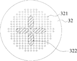
请参照图3、图4、图5及图6,其为现有技术另一种水雾产生器的分解图、剖面图、作动示意图及雾化区域示意图。为改善上述现有技术的缺点,中国台湾专利I331055揭露一种水雾产生器。图中,该水雾产生器2用以雾化一液体,且应用于一具有透孔的雾化装置。该水雾产生器2包含一制动环片21、一喷孔片22、一压电环片23及一腔体24,该喷孔片22设有多个击发孔221并夹设于该制动环片21及该压电环片23之间,并于该喷孔片22的中心处形成一雾化区域223。其中该喷孔片22的中心处形成一半球面的曲面结构222。Please refer to FIG. 3 , FIG. 4 , FIG. 5 and FIG. 6 , which are an exploded view, a sectional view, a schematic diagram of operation and a schematic diagram of the atomization area of another water mist generator in the prior art. In order to improve the above-mentioned shortcomings of the prior art, Chinese Taiwan patent I331055 discloses a water mist generator. In the figure, the
虽然凭借此种半球面结构设计,理论上可较现有技术增加雾化量,并降低集中于该喷孔片22中心处的应力,及产生较大的雾化区域223。然而,上述水雾产生器2,在实际应用时,仍有下述缺点:Although the hemispherical structure design can theoretically increase the amount of atomization compared with the prior art, reduce the stress concentrated at the center of the
1、当对此种具半球面结构的该喷孔片22进行加工时,因加工材料及加工特性的关系,对半球面的形状而言,会有加工深度与半球面曲率半径大小成相反的问题。为达上述增加雾化量的功效,该喷孔片22中心处加工深度须达一定深度。当半球面曲率半径越小时,就比较容易达到所需的深度。为达此半球面形状最佳雾化效能的深度,必定要缩小半球面的曲率半径。然而,有效雾化范围将被缩减。若要增大有效雾化范围,又须增大加工曲率半径,导致加工深度变浅,使雾化效能变差。若要于相同尺寸下可达到较小曲率半径所能加工的深度,该喷孔片22容易受过大应力,导致结构变形量超过其限制而破裂,或因降伏强度下降,经多次反复振动后而破裂。1. When processing the
2、由于该喷孔片22材料本身的特性,若加工后的半球面直径越长,结构张力也随的降低,造成输入力量减弱,抗低频共振的能力亦随的下降,容易产生伴随而来的噪音现象。2. Due to the characteristics of the material of the
3、此种雾化方式的封装结构,为能稳定夹持该喷孔片22,该制动环片21的内环径通常较该压电环片23的内环径为小,并使大部份振荡能量传递至该喷孔片22,及消除其半球面设计无法有效雾化的外围振动区域,造成该喷孔片22的部份该击发孔221的使用率下降,使得该喷孔片22上可雾化区域及雾化量相对减少。此外,当该压电环片21作动时,由于该压电环片21、该喷孔片22及该制动环片23各夹层之间的黏胶因施力臂不等长,容易于操作过程中导致各元件之间的胶着力失效。3. The encapsulation structure of this atomization method, in order to stably clamp the
4、由于现有技术喷孔片半球面结构的设计,其振动波能量经传递后,大部份仍会集中于中心区域,导致仅位于中心部分的微孔能有效作动,而外围区域的微孔则因振动能量不足而无法有效使用,导致雾化面积无法达到原设计面积。4. Due to the design of the hemispherical surface structure of the nozzle hole sheet in the prior art, after the vibration wave energy is transmitted, most of it will still be concentrated in the central area, so that only the micropores located in the central part can effectively move, while the micropores in the peripheral area Micropores cannot be used effectively due to insufficient vibration energy, resulting in the atomization area not reaching the original design area.
发明内容 Contents of the invention
本发明的主要目的,旨在提供一种喷孔片及使用其的雾化组件,其可借助于喷孔片上形成多个隆起部,而形成辐射状或环状排列的多曲面结构,以加大雾化区域,增加雾化过程稳定性、抑制低频振动及减少加工拉伸应力。The main purpose of the present invention is to provide an orifice plate and an atomizing assembly using it, which can form a radial or annular multi-curved surface structure by means of forming a plurality of ridges on the orifice plate to increase Large atomization area, increase the stability of the atomization process, suppress low-frequency vibration and reduce processing tensile stress.
为达上述目的,本发明的喷孔片,呈盘体状,包含:In order to achieve the above-mentioned purpose, the orifice plate of the present invention is in the shape of a disc, comprising:
多个击发孔,设于该喷孔片上;及a plurality of firing holes provided in the orifice sheet; and
多个第一隆起部,呈非圆形,设于该喷孔片上而以该喷孔片的中心间隔排列设置,该多个第一隆起部以该喷孔片的中心为基准作排列设置而形成一几何图案。A plurality of first bulges, non-circular in shape, are arranged on the orifice sheet and arranged at intervals with the center of the orifice sheet, and the plurality of first bulges are arranged and arranged with the center of the orifice sheet as a reference. form a geometric pattern.
其中,所述的喷孔片具有三个第一隆起部,该三个第一隆起部呈椭圆形且以一端朝向该喷孔片的中心而向外放射等间隔排列设置。Wherein, the orifice sheet has three first bulges, and the three first bulges are elliptical and arranged in equal intervals radially outward with one end facing the center of the orifice sheet.
其中,更包括多个第二隆起部,该各第二隆起部系间隔设置于对应的该等第一隆起部之间,且各该第二隆起部的隆起突伸方向系与各该第一隆起部的隆起突伸方向相同。Wherein, it further includes a plurality of second bulges, the second bulges are arranged at intervals between the corresponding first bulges, and the protruding direction of each second bulge is the same as that of each first bulge. The protrusions of the protrusions protrude in the same direction.
其中,该多个第二隆起部呈圆弧造形。Wherein, the plurality of second bulges are arc-shaped.
其中,所述的喷孔片具有三个第二隆起部,且该三个第二隆起部以该喷孔片的中心呈环状排列设置。Wherein, the orifice sheet has three second bulges, and the three second bulges are arranged in a circular arrangement at the center of the orifice sheet.
其中,该第二隆起部呈菱形、椭圆形、三角形、砂漏型、弯月形或心形。Wherein, the second raised part is in the shape of rhombus, ellipse, triangle, hourglass, meniscus or heart.
7.如权利要求6所述的喷孔片,其特征在于,该第二隆起部的横剖面为三角锥面、单弧面、斜面或梯形面。7 . The orifice plate according to claim 6 , wherein the cross-section of the second raised portion is a triangular conical surface, a single arc surface, an inclined surface or a trapezoidal surface.
其中,该喷孔片厚度与该第二隆起部高度的比例约为1∶0.5~1∶20之间。Wherein, the ratio of the thickness of the orifice sheet to the height of the second raised portion is about 1:0.5˜1:20.
其中,所述的喷孔片具有四个第一隆起部,该四个第一隆起部呈椭圆形且以一端朝向该喷孔片的中心而向外放射等间隔排列设置。Wherein, the orifice sheet has four first bulges, and the four first bulges are elliptical and arranged in equal intervals radially outwards with one end facing the center of the orifice sheet.
其中,该多个隆起部分别偏转一预设角度,且以一端朝向该喷孔片的中心而向外放射等间隔排列设置。Wherein, the plurality of bulges are respectively deflected by a predetermined angle, and arranged radially outward with one end facing the center of the orifice plate at equal intervals.
其中,所述的喷孔片具有三个第一隆起部,该三个第一隆起部呈圆弧造形且以该喷孔片的中心而环状排列设置。Wherein, the orifice sheet has three first bulges, and the three first bulges are arc-shaped and arranged in a ring around the center of the orifice sheet.
其中,所述的喷孔片具有九个第一隆起部,每三个相邻的该第一隆起部呈等间隔放射状排列。Wherein, the orifice sheet has nine first bulges, and every three adjacent first bulges are radially arranged at equal intervals.
其中,该第一隆起部的外形呈菱形、椭圆形、三角形、矩形、砂漏形、弯月形或心形。Wherein, the shape of the first bulge is rhombus, ellipse, triangle, rectangle, hourglass, meniscus or heart.
其中,该第一隆起部的横剖面为三角锥面、单弧面、斜面或梯形面。Wherein, the cross section of the first raised portion is a triangular cone surface, a single arc surface, an inclined surface or a trapezoidal surface.
其中,该喷孔片厚度与该第一隆起部高度的比例约为1∶0.5~1∶20之间。Wherein, the ratio of the thickness of the orifice sheet to the height of the first raised portion is about 1:0.5˜1:20.
本发明还提供一种雾化组件,设置于一腔体的一侧,其包含:The present invention also provides an atomization component, which is arranged on one side of a cavity, which includes:
一压电环片;a piezoelectric ring;
一制动环片,设于该压电环片一侧;及a braking ring disposed on one side of the piezoelectric ring; and
一如上所述的喷孔片,该喷孔片设置于该压电环片及该制动环片之间。An orifice sheet as described above, the orifice sheet is arranged between the piezoelectric ring sheet and the braking ring sheet.
其中,该制动环片的内环径等于该压电环片的内环径,该制动环片的外环径大于该压电环片的外环径。Wherein, the inner diameter of the brake ring is equal to the inner diameter of the piezoelectric ring, and the outer diameter of the brake ring is larger than the outer diameter of the piezoelectric ring.
其中,当该制动环片设置于邻近该腔体的一侧时,各该第一隆起部朝该压电环片的方向隆起突伸。Wherein, when the braking ring is arranged on a side adjacent to the cavity, each of the first raised portions protrudes toward the direction of the piezoelectric ring.
其中,当该压电环片设置于邻近该腔体的一侧时,各该第一隆起部朝该制动环片的方向隆起突伸。Wherein, when the piezoelectric ring is arranged on a side adjacent to the cavity, each of the first raised portions protrudes toward the braking ring.
附图说明 Description of drawings
图1为现有技术的一种雾化装置分解图;Fig. 1 is an exploded view of an atomizing device of the prior art;
图2为现有技术一种雾化装置的作动示意图;Fig. 2 is a schematic diagram of the operation of an atomization device in the prior art;
图3为现有技术另一种水雾产生器分解图;Fig. 3 is an exploded view of another water mist generator in the prior art;
图4为现有技术另一种水雾产生器剖面图;Fig. 4 is a sectional view of another water mist generator in the prior art;
图5为现有技术另一种水雾产生器作动示意图;Fig. 5 is a schematic diagram of the operation of another water mist generator in the prior art;
图6为现有技术另一种水雾产生器雾化区域示意图;Fig. 6 is a schematic diagram of the atomization area of another water mist generator in the prior art;
图7A为本发明喷孔片及使用其的雾化组件第一实施例分解图;Fig. 7A is an exploded view of the first embodiment of the orifice sheet and the atomization assembly using it of the present invention;
图7B为本发明喷孔片及使用其的雾化组件其喷孔片立体示意图;Fig. 7B is a three-dimensional schematic diagram of the orifice sheet of the present invention and the atomization assembly using it;
图8为本发明喷孔片及使用其的雾化组件第一实施例的剖视图;Fig. 8 is a cross-sectional view of the first embodiment of the orifice plate of the present invention and the atomization assembly using it;
图9为本发明喷孔片及使用其的雾化组件第一实施例喷孔片的平面示意图;Fig. 9 is a schematic plan view of the orifice plate of the present invention and the first embodiment of the orifice plate using the atomization assembly;
图10为本发明喷孔片及使用其的雾化组件较佳实施例的作动示意图;Figure 10 is a schematic diagram of the operation of a preferred embodiment of the nozzle hole sheet and the atomization assembly using it of the present invention;
图11为本发明喷孔片及使用其的雾化组件较佳实施例的雾化区域示意图;Fig. 11 is a schematic diagram of the atomization area of a preferred embodiment of the nozzle hole plate of the present invention and the atomization assembly using it;
图12为本发明喷孔片及使用其的雾化组件,喷孔片第二实施例示意图;Fig. 12 is a schematic diagram of the second embodiment of the orifice sheet and the atomization assembly using it of the present invention;
图13为本发明喷孔片及使用其的雾化组件,喷孔片第三实施例示意图;Fig. 13 is a schematic diagram of the third embodiment of the orifice sheet and the atomization assembly using it of the present invention;
图14为本发明喷孔片及使用其的雾化组件,喷孔片第四实施例示意图;Fig. 14 is a schematic diagram of the fourth embodiment of the orifice sheet and the atomization assembly using it of the present invention;
图15为本发明喷孔片及使用其的雾化组件,喷孔片第五实施例示意图;Fig. 15 is a schematic diagram of the fifth embodiment of the orifice sheet and the atomization assembly using it of the present invention;
图16为本发明喷孔片及使用其的雾化组件,喷孔片第六实施例示意图;Fig. 16 is a schematic diagram of the sixth embodiment of the orifice sheet and the atomization assembly using it of the present invention;
图17为本发明喷孔片及使用其的雾化组件,喷孔片第七实施例示意图;Fig. 17 is a schematic diagram of the seventh embodiment of the orifice sheet and the atomization assembly using it of the present invention;
图18A~图18K为本发明喷孔片及使用其的雾化组件,喷孔片外形示意图;Figures 18A to 18K are schematic diagrams of the nozzle hole sheet and the atomization component using it of the present invention, and the shape of the nozzle hole sheet;
图19A~图19E为本发明喷孔片及使用其的雾化组件,喷孔片隆起部横剖面示意图。19A to 19E are cross-sectional schematic diagrams of the orifice plate and the atomization assembly using it, and the raised part of the orifice plate of the present invention.
附图标记说明:Explanation of reference signs:
背景技术:1-雾化装置;11-雾化组件;111-制动环片;112-喷孔片;1121-击发孔;113-压电环片;12-腔体;2-水雾产生器;21-制动环片;22-喷孔片;221-击发孔;222-曲面结构;223-雾化区域;23-压电环片;24-腔体;Background technology: 1-atomization device; 11-atomization assembly; 111-brake ring; 112-nozzle hole; 1121-firing hole; 113-piezoelectric ring; 12-cavity; 2-water mist generation 21-brake ring; 22-nozzle hole; 221-firing hole; 222-surface structure; 223-atomization area; 23-piezoelectric ring; 24-cavity;
本发明:3-雾化组件;31-压电环片;311-外环径;312-内环径;32-喷孔片;321-击发孔;322-第一隆起部;323-第二隆起部;324-雾化区域;33-制动环片;331-外环径;332-内环径;34-腔体。The present invention: 3-atomization assembly; 31-piezoelectric ring; 311-outer ring diameter; 312-inner ring diameter; 32-nozzle hole; 321-firing hole; Protrusion; 324-atomization area; 33-brake ring; 331-outer ring diameter; 332-inner ring diameter; 34-cavity.
具体实施方式 Detailed ways
为使贵审查员能清楚了解本发明的内容,谨以下列说明搭配附图,敬请参阅。In order to enable your examiner to clearly understand the content of the present invention, the following descriptions are provided together with the accompanying drawings, please refer to them.
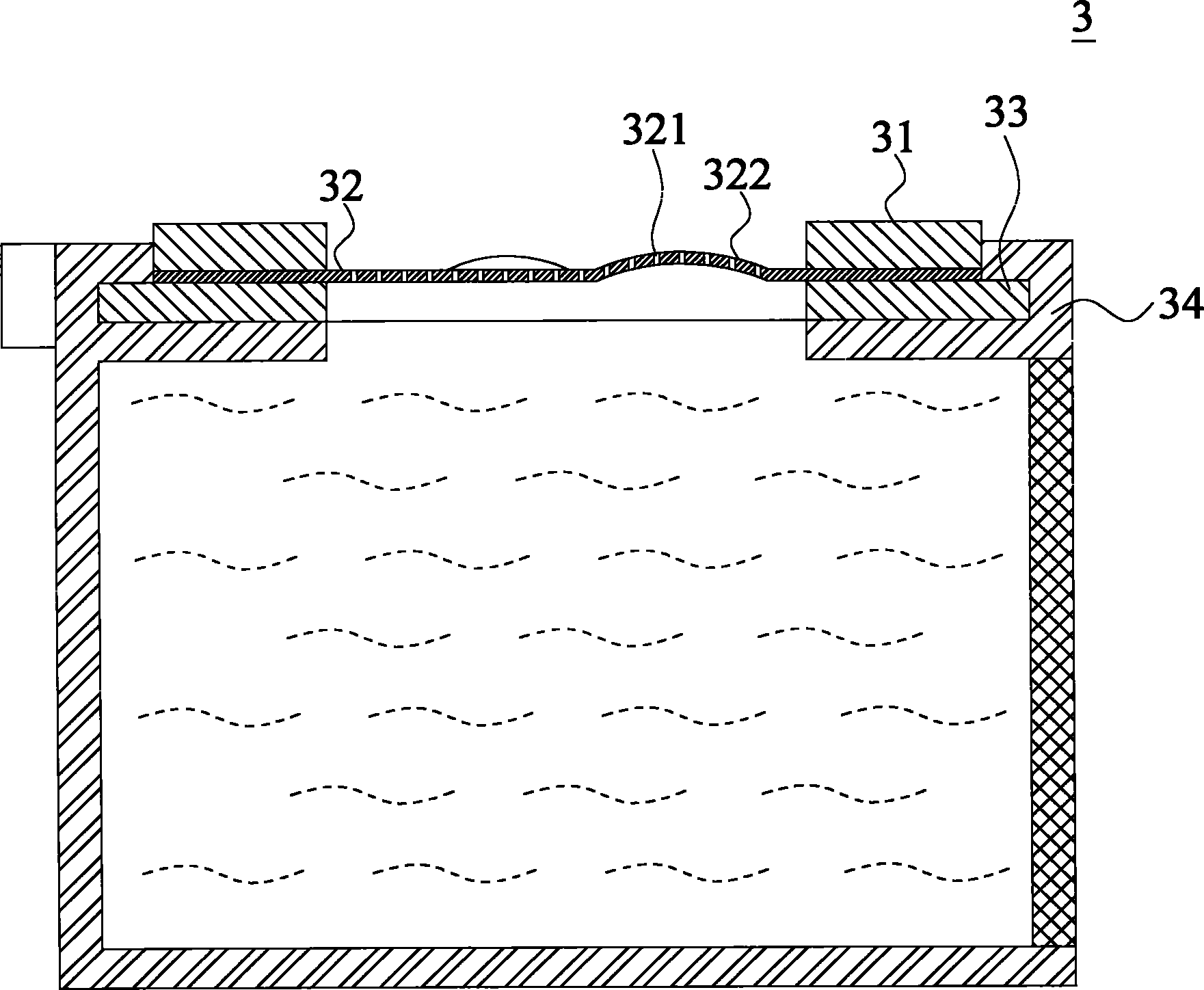
请参阅图7A、图7B、图8及图9所示,其为本发明喷孔片及使用其的雾化组件第一实施例的分解图、喷孔片示意图、剖视图及喷孔片的示意图。图中,该雾化组件3设置于一腔体34的一侧,并包含一压电环片31、一喷孔片32及一制动环片33。Please refer to Fig. 7A, Fig. 7B, Fig. 8 and Fig. 9, which are the exploded view, the schematic diagram of the nozzle hole sheet, the cross-sectional view and the schematic diagram of the nozzle hole sheet of the first embodiment of the atomization assembly using it according to the present invention. . In the figure, the
该压电环片31可以锆钛酸铅材料所构成的压电陶瓷来制造,并具有一外环径311及一内环径312。The
该制动环片33则为一金属材质的环片,其具有一外环径331及一内环径332,并设置于该压电环片31的一侧。在本实施例中,该制动环片33的内环径332与该压电环片31的内环径312相等,而该制动环片33的外环径331可大于该压电环片31的外环径311。The
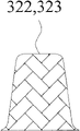
该喷孔片32则呈一盘体形状,其外径介于该压电环片31及该制动环片33的内环径及外环径之间,而可供夹设于其中。其中,该喷孔片32上可以准分子激光或其他方式间隔形成多个击发孔321,每一该第一隆起部322皆为非平面状的曲面结构,而该多个第一隆起部322呈非圆形且于该喷孔片32上排列形成一特定造型的几何图案。在第一实施例中,该多个第一隆起部322以三个来实施,且该多个隆起部322的外形呈一椭圆状,并以一端朝向该喷孔片32的中心呈等间隔放射状排列设置。此外,由剖面看来,该喷孔片32及该多个形成于该喷孔片32上的第一隆起部322呈一辐射状多曲面结构。此外,该喷孔片32与各该第一隆起部322高度的比例可为1∶0.5~1∶20之间,但不以此为限,可随加工技术或实际需求而增加或减少。The
当组装该雾化组件3时,可以一黏着剂(图中未示)接合该压电环片31、该喷孔片32及该制动环片33,并使该雾化组件3的该压电环片31或该制动环片33设置于邻近该腔体34的一侧。当该压电环片31设置于邻近该腔体34的一侧时,则各该第一隆起部322朝该制动环片33的方向隆起突伸,当该制动环片33设置于邻近该腔体34的一侧时,则各该第一隆起322部朝该压电环片31的方向隆起突伸,以发挥雾化效果。When assembling the
请参阅图10及图11,其为本发明雾化组件较佳实施例的作动示意图及雾化区域的示意图。当该雾化组件3开始运作时,通过输入一电压至该压电环片31,使该压电环片31产生反复性伸缩形变,并以振波形态传递能量至该喷孔片32,而使该喷孔片32振动。由于该喷孔片32通过设置该多个第一隆起部322,当该喷孔片32振动时,液体将受位于该多个第一隆起部322所形成的曲面区域及其邻近的平面区域的击发孔321,因瑞利波(或称表面波)的作用所击发而形成细小分子,并产生雾化作用,因此会形成一雾化区域324即该多个第一隆起部322及其邻近部位所构成的曲面与平面区域,而可远大于现有技术的雾化区域,而可充分使用喷孔片32上的击发孔321以增加雾化量,且能喷击出具微纳米等级且均匀分布的液滴。Please refer to FIG. 10 and FIG. 11 , which are the schematic diagrams of the operation and the schematic diagram of the atomization area of the preferred embodiment of the atomization component of the present invention. When the
其中,该喷孔片32上隆起部的排列方式及变化不仅以上述较佳实施例为限,亦可以如下所述的实施态样:Wherein, the arrangement and variation of the bulges on the
在第二实施例中,该喷孔片32具有四个第一隆起部322,该多个第一隆起部322的外形呈椭圆形,且以一端朝向该喷孔片32的中心而向外放射等间隔排列设置,且该喷孔片32表面更具有该多个击发孔321,如图12所示。In the second embodiment, the
在第三实施例中,该多个第一隆起部322具有四个第一隆起部322,各该第一隆起部322的外形呈椭圆形,则分别偏转一预设角度,且以一端朝向该喷孔片32的中心而向外放射等间隔排列设置,且该喷孔片32表面更具有该多个击发孔321,如图13所述。In the third embodiment, the plurality of
在第四实施例中,该喷孔片32具有三个第一隆起部322,该多个第一隆起部322的外形呈圆弧造型,且以该喷孔片32的中心而环状排列设置,且该喷孔片32表面更具有该多个击发孔321,如图14所示。In the fourth embodiment, the
在第五实施例中,该喷孔片32具有三个第一隆起部322,该多个第一隆起部322呈一端小一端大的弧形造型,该以该喷孔片32的中心而环状排列设置,且该喷孔片32表面更具有该多个击发孔321,如图15所示。In the fifth embodiment, the
在第六实施例中,该喷孔片32具有九个第一隆起部322,每三个相邻的该第一隆起部322可呈一组几何图案,并呈等间隔放射状排列,且该喷孔片32表面更具有该多个击发孔321,如图16所示。In the sixth embodiment, the
在第七实施例中,该喷孔片32,不但包括如第一实施例其对应的附图所呈现的该多个第一隆起部322,更包括三个第二隆起部323,该多个第二隆起部323朝与各该第一隆起部322的方向隆起突伸,并呈圆弧造形,并间隔设置于对应的该等第一隆起部之间,且该喷孔片32表面更具有该多个击发孔321,如图17所示。此外,该喷孔片32厚度与各该第二隆起部323的比例可为1∶0.5~1∶20之间,但不以此为限。In the seventh embodiment, the
其中,上述各实施例中,如图18A~图18K所示,该多个第一隆起部322及该多个第二隆起部323的外形不仅以上述附图为限,也可呈菱形(图18A)、椭圆形(图18C)、三角形(图18D、图18E)、矩形(图18H)、砂漏形(图18J)、弯月形(图中未示)、心形(图18K)或其他形状(图18B、图18F、图18G、图18I)。而各该第一隆起部322及各该第二隆起部323的数量及排列方式,亦不以上述实施方式为限,亦可为任意形状或数量所构成。Wherein, in each of the above-mentioned embodiments, as shown in FIGS. 18A to 18K , the shapes of the plurality of
其中,上述各实施例中,如图19A~图19E所示该多个第一隆起部322及该多个第二隆起部323的横剖面为三角锥面(图19A)、单弧面(图19B、图19E)、斜面(图19C)或梯形面(图19D),或为任意形式。Among them, in each of the above-mentioned embodiments, as shown in FIGS. 19A to 19E , the cross-sections of the plurality of
此外,该雾化组件3由于具有上述结构的该喷孔片32,更具有下述优点:In addition, the
1、由于雾化面积增大,而可提高该喷孔片32内外侧的液体及气体的交换速率,以增进雾化过程稳定性,减少喷雾量容易忽大忽小的现象。1. Due to the increase of the atomization area, the exchange rate of liquid and gas inside and outside the
2、与现有技术的单一半球面结构的喷孔片22相比较,各该第一隆起部322及各该第二隆起部323,所需的加工深度,由于雾化区域加大,其弯曲曲度便可调整至最佳值,并仅需现有技术的一半左右的加工深度即可。由于加工深度缩减,而可避免当喷孔片加工时,因应力过大而破裂。2. Compared with the
3、由各该第一隆起部322或各该第二隆起部323所组合排列形成的几何图案,在该喷孔片32形成的辐射状或环状排列多曲面结构,可打散改变传递其上的振动波行动方向,进而破坏振动波等向集中于该喷孔片32中心的规则性,以改善现有技术喷孔片因其中心区域振幅值过大,易应力集中而遭受破坏的缺点。3. The geometric pattern formed by the combination and arrangement of each of the
4、由于该喷孔片32所形成的辐射状多曲面结构,可提升每一曲面结构的结构张力,以强化抗低频共振的能力。4. Due to the radial multi-curved structure formed by the
5、由于该制动环片33的内环径332与该压电环片31的内环径312相等,而可于封装过程使切口对齐,而可确保该喷孔片32可以被紧密的夹持于中间,避免该压电环片31作动时,施力臂不等长,造成各夹层之间的胶着剂失效。5. Since the
6、由于该喷孔片32所形成的幅射状多曲面结构可有效传递及均匀分散振波能量,而使该具多曲面结构的喷孔片可产生共振的雾化面积区间遍及于非隆起部的其他位置,故相较于现有技术在相同单位面积的喷孔片的可雾化区域为多。6. Since the radial multi-curved surface structure formed by the
7、由于该喷孔片通过排列设置该多个隆起部而形成多曲面结构,此种结构可使与其配合的压电环片,即使其未能作动于一单一操作频率下而产生微量偏移跳动的情况下,工作时仍能保持有效的雾化量,相较现有技术须配合非常高精度的压电环片与驱动电路才能有效运作而言,更能降低制造成本。7. Since the orifice plate forms a multi-curved surface structure by arranging the plurality of ridges, this structure can make the piezoelectric ring piece matched with it produce a slight deviation even if it cannot operate at a single operating frequency. In the case of moving and bouncing, the effective atomization amount can still be maintained during operation. Compared with the existing technology, which requires a very high-precision piezoelectric ring and a driving circuit to operate effectively, it can further reduce the manufacturing cost.
然而,以上所述,仅为本发明的较佳实施例而已,并非用以限定本发明实施的范围,在不脱离本发明的精神与范围下所作的均等变化与修饰,皆应涵盖于本发明的专利范围内。However, the above descriptions are only preferred embodiments of the present invention, and are not intended to limit the scope of the present invention. All equivalent changes and modifications made without departing from the spirit and scope of the present invention should be covered by the present invention. within the scope of the patent.
综上所述,本发明的雾化组件,具有专利的发明性,及对产业的利用价值;申请人爰依专利法的规定,向钧局提起发明专利的申请。To sum up, the atomization component of the present invention has the inventiveness of the patent and the utility value to the industry; the applicant filed an application for the invention patent with the Jun Bureau in accordance with the provisions of the Patent Law.
Claims (19)
Priority Applications (1)
| Application Number | Priority Date | Filing Date | Title |
|---|---|---|---|
| CN2011100403615A CN102641816A (en) | 2011-02-18 | 2011-02-18 | Orifice sheet and atomizing components using it |
Applications Claiming Priority (1)
| Application Number | Priority Date | Filing Date | Title |
|---|---|---|---|
| CN2011100403615A CN102641816A (en) | 2011-02-18 | 2011-02-18 | Orifice sheet and atomizing components using it |
Publications (1)
| Publication Number | Publication Date |
|---|---|
| CN102641816A true CN102641816A (en) | 2012-08-22 |
Family
ID=46655041
Family Applications (1)
| Application Number | Title | Priority Date | Filing Date |
|---|---|---|---|
| CN2011100403615A Pending CN102641816A (en) | 2011-02-18 | 2011-02-18 | Orifice sheet and atomizing components using it |
Country Status (1)
| Country | Link |
|---|---|
| CN (1) | CN102641816A (en) |
Cited By (5)
| Publication number | Priority date | Publication date | Assignee | Title |
|---|---|---|---|---|
| CN103223389A (en) * | 2013-04-02 | 2013-07-31 | 张建辉 | Piezoceramic ultrasonic atomizer |
| WO2015003630A1 (en) * | 2013-07-10 | 2015-01-15 | 金进精密泵业制品(深圳)有限公司 | Ultrasonic atomization optical beauty instrument |
| CN105855117A (en) * | 2014-11-25 | 2016-08-17 | 微邦科技股份有限公司 | Atomizing device capable of increasing atomizing amount |
| WO2020088336A1 (en) * | 2018-10-29 | 2020-05-07 | 湖南中烟工业有限责任公司 | Ultrasonic atomization piece, atomizer, and electronic cigarette |
| WO2023221616A1 (en) * | 2022-05-18 | 2023-11-23 | 海南摩尔兄弟科技有限公司 | Electronic atomization device and atomizer |
Citations (7)
| Publication number | Priority date | Publication date | Assignee | Title |
|---|---|---|---|---|
| JPS58202071A (en) * | 1982-05-20 | 1983-11-25 | Matsushita Electric Ind Co Ltd | atomization device |
| JPS60132671A (en) * | 1983-12-19 | 1985-07-15 | Matsushita Electric Ind Co Ltd | atomization pump |
| TW200635670A (en) * | 2005-04-01 | 2006-10-16 | Ind Tech Res Inst | Device for creating fine mist |
| CN1923377A (en) * | 2005-08-30 | 2007-03-07 | 财团法人工业技术研究院 | Atomizer structure |
| CN1990118A (en) * | 2005-12-30 | 2007-07-04 | 财团法人工业技术研究院 | Resonant frequency modulation method and device for micro-spray system |
| US20080073447A1 (en) * | 2006-09-25 | 2008-03-27 | Liang-De Wang | Liquid atomizer |
| CN201371109Y (en) * | 2009-03-05 | 2009-12-30 | 合世生医科技股份有限公司 | Droplet generating apparatus |
-
2011
- 2011-02-18 CN CN2011100403615A patent/CN102641816A/en active Pending
Patent Citations (7)
| Publication number | Priority date | Publication date | Assignee | Title |
|---|---|---|---|---|
| JPS58202071A (en) * | 1982-05-20 | 1983-11-25 | Matsushita Electric Ind Co Ltd | atomization device |
| JPS60132671A (en) * | 1983-12-19 | 1985-07-15 | Matsushita Electric Ind Co Ltd | atomization pump |
| TW200635670A (en) * | 2005-04-01 | 2006-10-16 | Ind Tech Res Inst | Device for creating fine mist |
| CN1923377A (en) * | 2005-08-30 | 2007-03-07 | 财团法人工业技术研究院 | Atomizer structure |
| CN1990118A (en) * | 2005-12-30 | 2007-07-04 | 财团法人工业技术研究院 | Resonant frequency modulation method and device for micro-spray system |
| US20080073447A1 (en) * | 2006-09-25 | 2008-03-27 | Liang-De Wang | Liquid atomizer |
| CN201371109Y (en) * | 2009-03-05 | 2009-12-30 | 合世生医科技股份有限公司 | Droplet generating apparatus |
Cited By (6)
| Publication number | Priority date | Publication date | Assignee | Title |
|---|---|---|---|---|
| CN103223389A (en) * | 2013-04-02 | 2013-07-31 | 张建辉 | Piezoceramic ultrasonic atomizer |
| WO2015003630A1 (en) * | 2013-07-10 | 2015-01-15 | 金进精密泵业制品(深圳)有限公司 | Ultrasonic atomization optical beauty instrument |
| CN105855117A (en) * | 2014-11-25 | 2016-08-17 | 微邦科技股份有限公司 | Atomizing device capable of increasing atomizing amount |
| CN105855117B (en) * | 2014-11-25 | 2018-07-17 | 微邦科技股份有限公司 | Atomizing device capable of increasing atomizing amount |
| WO2020088336A1 (en) * | 2018-10-29 | 2020-05-07 | 湖南中烟工业有限责任公司 | Ultrasonic atomization piece, atomizer, and electronic cigarette |
| WO2023221616A1 (en) * | 2022-05-18 | 2023-11-23 | 海南摩尔兄弟科技有限公司 | Electronic atomization device and atomizer |
Similar Documents
| Publication | Publication Date | Title |
|---|---|---|
| TWI458558B (en) | Spray holes and the use of its atomization module | |
| JP5984359B2 (en) | Ultrasonic atomization unit | |
| CN102641816A (en) | Orifice sheet and atomizing components using it | |
| CN102553767A (en) | Piezoelectric ceramic ultrasonic atomizing sheet | |
| CN110090744A (en) | Ultrasonic atomizer with Acoustic focusing device | |
| CN109261428A (en) | Piezoelectric ceramic atomizer | |
| CN201371109Y (en) | Droplet generating apparatus | |
| JP3153019U (en) | Fine droplet generator | |
| CN101773893B (en) | Combined ultrasonic atomization device | |
| CN103223389A (en) | Piezoceramic ultrasonic atomizer | |
| CN105855117B (en) | Atomizing device capable of increasing atomizing amount | |
| CN202314767U (en) | Microporous atomizing device | |
| CN201744425U (en) | Ultrasonic-focusing liquid sprayer | |
| US20120091224A1 (en) | Microdroplet Generation Apparatus | |
| JPH04150968A (en) | Ultrasonic wave atomizer | |
| CN204412540U (en) | Atomization device that can increase the amount of atomization | |
| CN101879493A (en) | Ultrasonic focusing liquid sprayer | |
| CN203598991U (en) | Piezoceramic atomizer | |
| CN201179489Y (en) | Low-energy-consumption ultrasonic atomization device | |
| CN107433243A (en) | A kind of microporous piezoceramic atomization sheet | |
| TWM408414U (en) | Nozzle sheet and atomization module thereof | |
| JP3178142U (en) | Micro drop generator | |
| CN117884297B (en) | Composite piezoelectric ceramic microporous atomizing sheet | |
| JP2599844B2 (en) | Ultrasonic generator | |
| CN112122052A (en) | A high-efficiency atomizing device |
Legal Events
| Date | Code | Title | Description |
|---|---|---|---|
| C06 | Publication | ||
| PB01 | Publication | ||
| C10 | Entry into substantive examination | ||
| SE01 | Entry into force of request for substantive examination | ||
| C02 | Deemed withdrawal of patent application after publication (patent law 2001) | ||
| WD01 | Invention patent application deemed withdrawn after publication |
Application publication date: 20120822 |