CN102634761B - Method for magnetic filtration of strip-sectional vacuum cathodic arc plasma - Google Patents
Method for magnetic filtration of strip-sectional vacuum cathodic arc plasma Download PDFInfo
- Publication number
- CN102634761B CN102634761B CN201110290648.3A CN201110290648A CN102634761B CN 102634761 B CN102634761 B CN 102634761B CN 201110290648 A CN201110290648 A CN 201110290648A CN 102634761 B CN102634761 B CN 102634761B
- Authority
- CN
- China
- Prior art keywords
- plasma
- bending
- vacuum
- banded
- magnetic
- Prior art date
- Legal status (The legal status is an assumption and is not a legal conclusion. Google has not performed a legal analysis and makes no representation as to the accuracy of the status listed.)
- Expired - Fee Related
Links
- 238000001914 filtration Methods 0.000 title claims abstract description 54
- 238000000034 method Methods 0.000 title claims abstract description 38
- 238000005452 bending Methods 0.000 claims abstract description 68
- 239000002245 particle Substances 0.000 claims abstract description 27
- 230000007935 neutral effect Effects 0.000 claims abstract description 6
- 238000010891 electric arc Methods 0.000 claims description 13
- 239000007789 gas Substances 0.000 claims description 9
- 210000003127 knee Anatomy 0.000 claims description 6
- 230000004323 axial length Effects 0.000 claims description 2
- 238000005520 cutting process Methods 0.000 claims description 2
- 230000005855 radiation Effects 0.000 claims description 2
- 230000005540 biological transmission Effects 0.000 claims 1
- 230000015572 biosynthetic process Effects 0.000 claims 1
- 239000011248 coating agent Substances 0.000 abstract description 12
- 238000000576 coating method Methods 0.000 abstract description 12
- 230000008021 deposition Effects 0.000 abstract description 5
- 230000004048 modification Effects 0.000 abstract description 4
- 238000012986 modification Methods 0.000 abstract description 4
- 230000007547 defect Effects 0.000 abstract description 3
- 239000000463 material Substances 0.000 abstract description 3
- 239000006115 industrial coating Substances 0.000 abstract 1
- 239000010408 film Substances 0.000 description 14
- 230000000694 effects Effects 0.000 description 4
- 239000010406 cathode material Substances 0.000 description 3
- 238000000151 deposition Methods 0.000 description 3
- 238000009826 distribution Methods 0.000 description 3
- 238000004804 winding Methods 0.000 description 3
- 230000007812 deficiency Effects 0.000 description 2
- 238000005516 engineering process Methods 0.000 description 2
- 238000001704 evaporation Methods 0.000 description 2
- 230000008020 evaporation Effects 0.000 description 2
- 230000007246 mechanism Effects 0.000 description 2
- 239000010409 thin film Substances 0.000 description 2
- RYGMFSIKBFXOCR-UHFFFAOYSA-N Copper Chemical compound [Cu] RYGMFSIKBFXOCR-UHFFFAOYSA-N 0.000 description 1
- HEVGGTGPGPKZHF-UHFFFAOYSA-N Epilaurene Natural products CC1C(=C)CCC1(C)C1=CC=C(C)C=C1 HEVGGTGPGPKZHF-UHFFFAOYSA-N 0.000 description 1
- 230000009471 action Effects 0.000 description 1
- 229910052802 copper Inorganic materials 0.000 description 1
- 239000010949 copper Substances 0.000 description 1
- 230000018109 developmental process Effects 0.000 description 1
- 238000010586 diagram Methods 0.000 description 1
- 238000009792 diffusion process Methods 0.000 description 1
- 230000005611 electricity Effects 0.000 description 1
- 230000005672 electromagnetic field Effects 0.000 description 1
- 239000007888 film coating Substances 0.000 description 1
- 238000009501 film coating Methods 0.000 description 1
- 238000009776 industrial production Methods 0.000 description 1
- 238000005468 ion implantation Methods 0.000 description 1
- 238000002955 isolation Methods 0.000 description 1
- 238000005304 joining Methods 0.000 description 1
- 208000001491 myopia Diseases 0.000 description 1
- 230000004379 myopia Effects 0.000 description 1
- 238000007747 plating Methods 0.000 description 1
- 230000009467 reduction Effects 0.000 description 1
- 239000000758 substrate Substances 0.000 description 1
Images


Landscapes
- Plasma Technology (AREA)
- Physical Vapour Deposition (AREA)
Abstract
The invention provides a method for removing electrically neutral drops and macroscopic particles in strip-sectional vacuum cathodic arc plasma, which belongs to the field of vacuum surface modification for materials, and particularly provides a method for magnetic filtration of electrically neutral drops and macroscopic particles by bending strip vacuum cathodic arc plasma by applying a magnetic field to a strip-sectional vacuum cathodic arc plasma channel. By the method, the defects that deposition area is small, deposition film is uneven, and scanning system equipment is complex and expensive and unsuitable for large-scale industrial coating application and the like in existing vacuum cathodic arc magnetic filtration methods for bends are overcome. By the method, coating plasma can be provided within a long strip range. By means of a rotating workpiece target table, application field of filtering arc can be widened greatly. Deposition efficiency is improved, large-space coating is achieved, coating efficiency is improved, and cost is reduced.
Description
Technical field
The present invention relates to electroneutral drop in a kind of vacuum cathode electric arc and the filter method of macroscopic particles, specifically be a kind of with carrying out bending vacuum cathode arc plasma in magnetic field, filter out the magnetic filter method of electroneutral drop and macroscopic particles, belong to the vacuum surface modification field of material.
Background technology
The technical development of material vacuum cathode arc coating deposition, to today, has obtained the achievement attracting people's attention, and becomes the coating technique that surface modification field is most widely used.But this film coating method still has some problems at present, be mainly manifested in due to the method rely on be vacuum cathode arc evaporation cathode material obtain arc plasma, there is very large current density at arc cathode spot place and (reach 10
6-10
8a/cm
2), therefore, even under vacuum, the cathode spot of vacuum arc also has very high temperature, makes cathode material fusing, forms small molten bath at cathode spot place, and the cathode material steam also producing in molten bath, therefore there is very large pressure reduction at cathode spot center with outside, make the drop in molten bath splash or cathode targets is burst apart, thereby produce some drops and macroscopic particles.The unfavorable factors such as these drops and macroscopic particles arrive substrate surface, will pollute rete, affect the effect of modified layer, cause workpiece surface coarse, and the performance of film is inhomogeneous.
In recent years, develop in the world the method for much removing drop and macroscopic particles, patent applicant has carried out summing up to the method for multiple filtration drop and macroscopic particles and (has seen that applicant is published in document " Magnetic Filter of Cathode Arc Ion Coating " vacuum 1999 on vacuum magazine, 3:14), and by filter method be divided into linear type structure and curvilinear style structure.In various drops and macroscopic particles filter method, adopt the filter method of magnetic structure constraint directing plasma to be widely used, also obtain good effect.Also some patents have been applied at home and abroad, as the patent of Chen Baoqing application, the patent No. 01247038.4, the title of this patent is to prepare the massenfilter of the ion source device of superhard thin film, patent content is: a kind of massenfilter of the ion source device of preparing superhard thin film, comprise filter tube, be arranged at the outside and solenoid coil joining with magnetic field power supply of filter tube, the exit aperture that is arranged at filter tube exit, in described filter tube, be provided with trap, described solenoid coil is formed by wire coiling, and described filter tube is bellows structure; Described filter tube is bend pipe.The United States Patent (USP) of Shi Xu application, the patent No. 6031239, the title of this patent is filtering cathode arc source, the content of patent is: use the two curved strainers of antarafacial and high energy electricity/magnetic filtering except unnecessary drop and macroscopic particles and uncharged particle.Above-mentioned patent can effectively be removed drop and macroscopic particles, obtains high-quality film.But, above-mentioned patent be mainly for the little vacuum cathode electric arc of circle structure, adding of magnetic field, make the plasma body of dispersing out from vacuum cathode arc source the inside with strong directivity, plated region is dwindled greatly, therefore, limited the application of the vacuum arc evaporation source after filtration on large-scale industry plating piece.And because the constraint in the magnetic field that in above-mentioned each bending magnetic filter, electronics is subject to ion is different, and conventionally in the outside of bend pipe ion affluence, inner side ion deficiency, causes plated film inhomogeneous.Therefore, in order to expand plated region, some bending electric arc magnetic filters are also reequiped, and have increased plasma focus mechanism and scanning mechanism, have increased the complicacy of equipment, complex structure, and cost is high.For this feature, therefore, in order to make to widen vacuum cathode arc coating deposition method after filtration in industrial application, also need to develop filter method and the device of new drop and macroscopic particles.
Summary of the invention
The present invention is directed to existing above-mentioned deficiency and defect in background technology, a kind of magnetic filter method of banded vacuum cathode arc plasma is provided, makes it overcome that existing bend pipe vacuum cathode electric arc magnetic filter method deposition region is little, deposited film is inhomogeneous, be not suitable for the defect of large-scale industry plated film application.The method can be in vacuum cavity one side, the plasma body that vacuum cathode arc source is sent enters vacuum cavity with banded scope, the plasma body that provides plated film to use, coordinate rotational workpieces target platform, can be in the coating film area of whole cavity, obtain plasma coating space, thereby greatly widen the service efficiency of filtered arc.Realize large space plated film, raise the efficiency cost-saving.
The step that the inventive method realizes is as follows:
The method be first to carry out below vacuum, take out back end vacuum pressure and be less than 5 × 10
-3after Pa, with machinery or the known striking method such as high pressure or the laser radiation electric arc that ignites, flame current is at 25A-1000A, voltage, at 20-59V, carries out plated film.Now, can pass into the mixed gas of rare gas element or rare gas element and other gases, be Pa to 10 to air pressure to vacuum tightness
-3the order of magnitude of Pa, carries out plated film.
Need to carrying out the bending vacuum cathode arc source filtering, to adopt the rectangular or two ends of rectangle be oval-shaped banded vacuum cathode arc source.The major axis 1 that it is characterized in that banded length is greater than wide axial length w, and l/w is more than 1.5.Need to carry out the bending vacuum cathode arc source filtering and also can adopt multiple cylindrical arc source arranged together, it is characterized in that more than at least two.
The plasma body being produced by banded vacuum cathode arc source is finally also outwards launched with band shape.Its band shape can be to form through the scanning of banded direction via a point-like plasma.
This vacuum cathode arc source is under the effect in a magnetic field, realizes the even motion of electric arc on surface, and the control of its motion can be that the magnetic field producing by permanent magnet is controlled, and can be also that the magnetic field that electro-magnet produces is controlled.
Before the vacuum cathode electric arc target of banded vacuum cathode arc source, place a cross section with the consistent band shaped plasma magnetic field bending channel of banded vacuum cathode arc source.It is characterized in that, in plasma body bending channel outside, being wound with magneticfield coil, or being placed with permanent magnet, magneticfield coil and permanent magnet can produce the magnetic field substantially parallel with the bending magnetic filtration channel of band shaped plasma wall in plasma body bending channel inside.Magnetic field can be long line structure, can be also can line cutting structure.Banded vacuum cathode arc plasma via this bending electric arc pipeline after, uncharged microscopic droplets and macroscopic particles and center particle are all filtered on the bending magnetic filtration channel of band shaped plasma wall.
The scope of the magneticstrength substantially parallel with the bending magnetic filtration channel of band shaped plasma wall is: while adopting electromagnetic field, magneticstrength is at 10mT-100mT; While adopting permanent magnet, magneticstrength is at 10-400mT.
Can there be two kinds of forms in the magnetic field applying on the bending magnetic filtration channel of band shaped plasma: the one, along on the length direction of the belt section of the bending magnetic filtration channel of band shaped plasma, magnetic field will evenly or substantially be uniformly distributed, the plasma body producing like this deflects just can be through the bending magnetic filtration channel of band shaped plasma time on the length direction of belt section, distortion and cause exit along skewness on banded Way out; The 2nd, banded bending plasma body by passage on, the magnetic field applying can adopt magneticstrength scanning to distribute, and scans along banded direction by magnetic field, obtains with this plasma body being evenly distributed in exit.
The bending of the bending magnetic filtration channel of band shaped plasma can be arc or knee shape or U-shaped or S shape or the meander-shaped such as how curved, it is characterized in that the bent magnetic field that inside has cardinal principle to parallel with band shaped plasma crooked pipeline inwall.Another one principal character is to be greater than 100mm from band shaped plasma from exit to the distance of vacuum cathode arc source.
Under the action of a magnetic field substantially parallel with the bending magnetic filtration channel of this band shaped plasma wall, the electronics in the arc plasma being evaporated from banded vacuum cathode arc source and ion will be subject to the constraint of Lauren time power.
Drop and macroscopic particles and neutral particle be not because charged, and therefore its motion can not be subject to the interference in magnetic field, continues to keep translational motion state, and encounters on wall.But still likely on band sigmoid pdp filter conduit wall, repeatedly rebound and enter coating chamber and pollute, in order to prevent this situation, can on the bending magnetic filtration channel of band shaped plasma inwall, add web or spoke, catch neutral particle, macroscopic particles and the drop of these bounce-backs, increase filter effect.
Below the present invention is done to further supplementary notes, particular content is as follows:
The existence in electronics and ion isolation region in this magnetic field, in the bending electric arc magnetic of general circular winding pipe formula filter method, can cause the shortcomings such as coating film thickness is inhomogeneous, but in the method, the band shaped plasma crooked pipeline of ribbon-like cross section due to what adopt, therefore, this uneven distribution will be uneven distribution on the width of banded exit, the sense of rotation of the rotary target platform of workpiece is consistent with this inhomogeneous direction, therefore this uneven distribution, can not work the mischief to the use of the inventive method.
Therefore, the present invention has the following advantages: method is simple, can be applicable to industrial production in enormous quantities.Can deposit without particle high surface finish film.
Brief description of the drawings
The bending magnetic filtration channel of the band shaped plasma example of Fig. 1 circular arc bending
Another of the bending magnetic filtration channel of the band shaped plasma magnetic field of Fig. 2 circular arc bending applies mode.
The differently curved method example of the bending magnetic filtration channel of Fig. 3 band shaped plasma
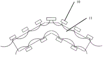
The bending magnetic filtration channel of Fig. 4 knee shape band shaped plasma cusped magnetic field applies mode example
Embodiment
Content below in conjunction with accompanying drawing and the inventive method provides embodiment, and the specific embodiment of the present invention is done further to understand.
Fig. 1 has provided the device schematic diagram that the band shaped plasma of utilizing present method to produce rectangular vacuum cathode arc source utilizes the bending magnetic filtration channel of band shaped plasma of circular arc bending to carry out magnetic filtration.Arc plasma enters the bending magnetic filtration channel 2 of band shaped plasma after producing via vacuum cathode electric arc target 1.In the bending magnetic filtration channel of the band shaped plasma outside of circular arc bending, be wound with the solenoid 3 that copper wires is wound around, solenoid 3 is centered around the bending magnetic filtration channel of band shaped plasma 2 outsides, forms along the parallel magnetic line of force (not providing in figure) of the bending magnetic filtration channel 2 inwalls cardinal principles of bending direction and band shaped plasma the bending magnetic filtration channel of band shaped plasma is inner.Under the constraint of this magnetic line of force, by the bending magnetic filtration channel outlet 4 of band shaped plasma, enter vacuum chamber, for plated film provides the plasma body of vacuum cathode electric arc band shape.Therefore, the plasma body of the long ribbon shape that this vacuum cathode arc plasma filter method can provide for plated film, the surface modifying method such as ion implantation, improves surface modification quality.
The winding method that is wrapped in the bending magnetic filtration channel 2 of band shaped plasma solenoid above can be continous way, also can adopt the interrupted mode winding around 5 shown in Fig. 2, its essential characteristic is to be formed in the bending magnetic filtration channel of band shaped plasma inside equally distributed magnetic field substantially parallel with the bending magnetic filtration channel of band shaped plasma inwall on bending direction.
In order to prevent the secondary bounce-back of drop and macroscopic particles and center particle, can in the bending magnetic filtration channel of band shaped plasma, add web or spoke 6.
The bending of the bending magnetic filtration channel of band shaped plasma, is not limited to Fig. 1 and Fig. 2 with given bowing, and bending angle is also not limited to 80 degree that provide in figure.Can also adopt the bending magnetic filtration channel 7 of S shape band shaped plasma as shown in Figure 3, or the bending magnetic filtration channel 8 of U-shaped band shaped plasma, or the bending magnetic filtration channel 9 of knee shape band shaped plasma, and the bending magnetic filtration channel of the band shaped plasma of other bend mode that do not provide.The bending magnetic filtration channel of these band shaped plasma all needs to have common feature, from the bending magnetic filtration channel of band shaped plasma exit, can not look at the cathode targets of vacuum cathode arc source straight.
The bending magnetic filtration channel of band shaped plasma magnetic filters the magnetic field of use, also can apply by permanent magnet, Fig. 4 has provided the bending magnetic filtration channel of knee shape band shaped plasma and has has extremely mutually connected and composed from beginning to end by the N utmost point and the S of permanent magnet 10 example that myopia is parallel to the cusped magnetic field 11 of the bending magnetic filtration channel of knee shape band shaped plasma inwall.This cusped magnetic field 11 also can prevent the diffusion to tube wall of charged particle in the band shaped plasma of admission passage in the direction of tube wall, and plasma body is sent to coating chamber (not providing in figure).
Claims (8)
1. the present invention is that a kind of pair cross-section or cross section, moving region are banded vacuum cathode arc plasma, carry out magnetic filtration, remove the wherein magnetic filter method of macroscopic particles and neutral particle: need to carry out the bending vacuum cathode arc source filtering and adopt long strip shape or rectangle or the oval banded vacuum cathode arc source of generation that waits, the major axis l that it is characterized in that banded length is greater than wide axial length w, and l/w is more than 1.5; The plasma body being produced by banded vacuum cathode arc source is finally also outwards launched with ribbon-like cross section.
2. according to claim 1, described cross section is that the formation of banded vacuum cathode arc plasma is a branch of plasma body producing via an arc spot, forms through the scanning of banded direction.
3. according to claim 1, the magnetic filter method of described macroscopic particles and neutral particle is before the vacuum cathode electric arc target of vacuum cathode arc source, places a cross-sectional shape with the consistent band shaped plasma magnetic field bending channel of banded vacuum cathode arc source.
4. according to claim 3, described cross section is that the feature of banded plasma body magnetic field bending channel is in plasma body bending channel outside, be wound with magneticfield coil, or be placed with permanent magnet, magneticfield coil and permanent magnet can produce the magnetic field substantially parallel with the bending magnetic filtration channel of band shaped plasma wall in plasma body bending channel inside: magnetic field is long line structure or meeting line cutting structure; There are two kinds of forms to apply magnetic field on the bending magnetic filtration channel of band shaped plasma, the one, along on the length direction of the belt section of the bending magnetic filtration channel of band shaped plasma, magnetic field will evenly or substantially be uniformly distributed; The 2nd, banded bending plasma body by passage on, the magnetic field energy article on plasma swept-volume, constraint, the transmission that apply, obtain with this plasma body being evenly distributed in exit.
5. cross section according to claim 4 is the method that the banded bending magnetic filtration channel of plasma body magnetic field applies, and the scope of the magneticstrength substantially parallel with conduit wall is 10mT-100mT in the time adopting electromagnetic mode; While adopting permanent magnet, magneticstrength is at 10-400mT.
6. according to claim 3, the bending of the bending magnetic filtration channel of described band shaped plasma is arc or knee shape or U-shaped or S shape or the meander-shaped such as how curved, it is characterized in that the magnetic field that inside has cardinal principle to parallel with band shaped plasma crooked pipeline inwall.
7. according to claim 3, the another one principal character of the described bending magnetic filtration channel of band shaped plasma is to be greater than 100mm from band shaped plasma pipeline exit to the distance of vacuum cathode arc source.
8. according to claim 1, first the realization of described method is to carry out below vacuum, takes out back end highest attainable vacuum to 5 × 10
-3after Pa, adding the mixed gas of rare gas element or rare gas element or rare gas element and other gases, is Pa to 10 to air pressure to vacuum tightness
-3the order of magnitude of Pa, with machinery or electronics or the known striking method such as the laser radiation electric arc that ignites, flame current is at 25A-1000A, and voltage is at 20-59V.
Priority Applications (1)
| Application Number | Priority Date | Filing Date | Title |
|---|---|---|---|
| CN201110290648.3A CN102634761B (en) | 2011-09-29 | 2011-09-29 | Method for magnetic filtration of strip-sectional vacuum cathodic arc plasma |
Applications Claiming Priority (1)
| Application Number | Priority Date | Filing Date | Title |
|---|---|---|---|
| CN201110290648.3A CN102634761B (en) | 2011-09-29 | 2011-09-29 | Method for magnetic filtration of strip-sectional vacuum cathodic arc plasma |
Publications (2)
| Publication Number | Publication Date |
|---|---|
| CN102634761A CN102634761A (en) | 2012-08-15 |
| CN102634761B true CN102634761B (en) | 2014-06-11 |
Family
ID=46619337
Family Applications (1)
| Application Number | Title | Priority Date | Filing Date |
|---|---|---|---|
| CN201110290648.3A Expired - Fee Related CN102634761B (en) | 2011-09-29 | 2011-09-29 | Method for magnetic filtration of strip-sectional vacuum cathodic arc plasma |
Country Status (1)
| Country | Link |
|---|---|
| CN (1) | CN102634761B (en) |
Families Citing this family (12)
| Publication number | Priority date | Publication date | Assignee | Title |
|---|---|---|---|---|
| CN105887035B (en) * | 2014-12-23 | 2018-06-05 | 北京师范大学 | Circular cathodic vacuum arc source plasma Magnetic filter rectangle ejector |
| CN105039914A (en) * | 2015-04-22 | 2015-11-11 | 常州大学 | Multi-arc ion plating accelerating system |
| CN106868463B (en) * | 2017-03-03 | 2019-02-15 | 北京航空航天大学 | Vacuum cathode arc ion plating device and method for controlling arc spot etching area |
| CN109600895B (en) * | 2018-11-15 | 2020-11-10 | 合肥聚能电物理高技术开发有限公司 | High density hot cathode plasma source |
| CN111074215B (en) * | 2019-12-27 | 2021-07-02 | 季华实验室 | A Novel Cathodic Arc Particle Filter |
| CN111763910B (en) * | 2020-07-14 | 2021-02-09 | 佛山耐信涂层技术有限公司 | Device and method for preparing amorphous diamond film, amorphous diamond film and composite coating thereof |
| CN111763918A (en) * | 2020-07-17 | 2020-10-13 | 广东鼎泰机器人科技有限公司 | Magnetic pipe bending mechanism for target material |
| CN111826619A (en) * | 2020-07-24 | 2020-10-27 | 九牧厨卫股份有限公司 | Electroplating pre-plating process for plastic metallization |
| CN114457310B (en) * | 2022-02-28 | 2023-08-29 | 广东鼎泰高科技术股份有限公司 | Visual vacuum cathode magnetic filter device |
| CN114717521A (en) * | 2022-04-22 | 2022-07-08 | 安徽纯源镀膜科技有限公司 | A antarafacial ion current channel for pure ion coating film |
| CN117512528A (en) * | 2022-07-27 | 2024-02-06 | 安徽纯源镀膜科技有限公司 | Device for improving deposition rate of magnetic filtration arc ion plating |
| CN115821218B (en) * | 2022-12-23 | 2024-12-13 | 季华实验室 | Film coating device and film coating method |
Citations (2)
| Publication number | Priority date | Publication date | Assignee | Title |
|---|---|---|---|---|
| US5478608A (en) * | 1994-11-14 | 1995-12-26 | Gorokhovsky; Vladimir I. | Arc assisted CVD coating method and apparatus |
| CN1195035A (en) * | 1997-03-31 | 1998-10-07 | 三星电子株式会社 | Thin-film deposition apparatus using cathodic arc discharge |
-
2011
- 2011-09-29 CN CN201110290648.3A patent/CN102634761B/en not_active Expired - Fee Related
Patent Citations (2)
| Publication number | Priority date | Publication date | Assignee | Title |
|---|---|---|---|---|
| US5478608A (en) * | 1994-11-14 | 1995-12-26 | Gorokhovsky; Vladimir I. | Arc assisted CVD coating method and apparatus |
| CN1195035A (en) * | 1997-03-31 | 1998-10-07 | 三星电子株式会社 | Thin-film deposition apparatus using cathodic arc discharge |
Also Published As
| Publication number | Publication date |
|---|---|
| CN102634761A (en) | 2012-08-15 |
Similar Documents
| Publication | Publication Date | Title |
|---|---|---|
| CN102634761B (en) | Method for magnetic filtration of strip-sectional vacuum cathodic arc plasma | |
| JP6625793B2 (en) | Vacuum arc plasma immersion coating deposition and ion treatment | |
| CN101792895B (en) | Cathodic vacuum arc source film depositing device and method for depositing film | |
| CN106868463B (en) | Vacuum cathode arc ion plating device and method for controlling arc spot etching area | |
| CN102953035B (en) | Multi-mode atternation coupling magnetic field assisted electrical arc ion plating deposition arc source apparatus | |
| US20110226617A1 (en) | Dielectric deposition using a remote plasma source | |
| CN102471878B (en) | Film formation apparatus | |
| KR101344085B1 (en) | Film-forming method and film-forming apparatus | |
| CN201660693U (en) | Cathodic vacuum arc source film deposition device | |
| CN203700496U (en) | Device for coating diamond-like carbon films | |
| CN105296938A (en) | Tree-shaped cathode vacuum arc plasma deposition and magnetic filtration device | |
| CN202072760U (en) | Arc ion plating device | |
| CN111748777A (en) | A variable angle variable diameter magnetic filter cathodic arc film deposition device and method | |
| WO2006104055A1 (en) | Droplet removing device and method in plasma generator | |
| CN114318246A (en) | Magnetic filtration vacuum deposition coating equipment and method for scanning magnetic field guided deposition coating | |
| JP5554451B2 (en) | Filter for removing macro particles from plasma beam | |
| CN100591797C (en) | Device for Improving the Quality of Arc Ion Plating Deposited Film | |
| CN203065569U (en) | Multi-magnetic-field structural adaptive control magnetic field group device | |
| CN114318247A (en) | Vacuum deposition coating equipment and coating method for magnetic field guiding filtration | |
| CN201132848Y (en) | A device for depositing high-quality thin films by arc ion plating | |
| JP5264168B2 (en) | Coating apparatus and coating method for coating a substrate | |
| CN103668061A (en) | Coating equipment for diamond-like carbon film with high adhesive force, high hardness and low friction-coefficient | |
| CN108330464B (en) | Wire rod diamond-like coating processingequipment | |
| CN100487156C (en) | Metal plate belt vacuum film coating equipment | |
| CN108441826A (en) | A kind of gas ion source, metal ion source and electron source enhancing arc source and arc current excitation |
Legal Events
| Date | Code | Title | Description |
|---|---|---|---|
| DD01 | Delivery of document by public notice |
Addressee: Li Liuhe Document name: Deemed not to require novelty, wide term notice |
|
| C06 | Publication | ||
| PB01 | Publication | ||
| C10 | Entry into substantive examination | ||
| SE01 | Entry into force of request for substantive examination | ||
| DD01 | Delivery of document by public notice |
Addressee: Li Liuhe Document name: Notification of Patent Invention Entering into Substantive Examination Stage |
|
| C14 | Grant of patent or utility model | ||
| GR01 | Patent grant | ||
| CF01 | Termination of patent right due to non-payment of annual fee |
Granted publication date: 20140611 Termination date: 20140929 |
|
| EXPY | Termination of patent right or utility model |