CN102577015A - Self-diagnosis device for power storage system - Google Patents
Self-diagnosis device for power storage system Download PDFInfo
- Publication number
- CN102577015A CN102577015A CN201180003928XA CN201180003928A CN102577015A CN 102577015 A CN102577015 A CN 102577015A CN 201180003928X A CN201180003928X A CN 201180003928XA CN 201180003928 A CN201180003928 A CN 201180003928A CN 102577015 A CN102577015 A CN 102577015A
- Authority
- CN
- China
- Prior art keywords
- state
- storage device
- diagnosis
- self
- power storage
- Prior art date
- Legal status (The legal status is an assumption and is not a legal conclusion. Google has not performed a legal analysis and makes no representation as to the accuracy of the status listed.)
- Pending
Links
Images


Classifications
-
- H—ELECTRICITY
- H01—ELECTRIC ELEMENTS
- H01M—PROCESSES OR MEANS, e.g. BATTERIES, FOR THE DIRECT CONVERSION OF CHEMICAL ENERGY INTO ELECTRICAL ENERGY
- H01M10/00—Secondary cells; Manufacture thereof
- H01M10/42—Methods or arrangements for servicing or maintenance of secondary cells or secondary half-cells
- H01M10/48—Accumulators combined with arrangements for measuring, testing or indicating the condition of cells, e.g. the level or density of the electrolyte
-
- H—ELECTRICITY
- H01—ELECTRIC ELEMENTS
- H01M—PROCESSES OR MEANS, e.g. BATTERIES, FOR THE DIRECT CONVERSION OF CHEMICAL ENERGY INTO ELECTRICAL ENERGY
- H01M10/00—Secondary cells; Manufacture thereof
- H01M10/42—Methods or arrangements for servicing or maintenance of secondary cells or secondary half-cells
- H01M10/4207—Methods or arrangements for servicing or maintenance of secondary cells or secondary half-cells for several batteries or cells simultaneously or sequentially
-
- H—ELECTRICITY
- H01—ELECTRIC ELEMENTS
- H01M—PROCESSES OR MEANS, e.g. BATTERIES, FOR THE DIRECT CONVERSION OF CHEMICAL ENERGY INTO ELECTRICAL ENERGY
- H01M10/00—Secondary cells; Manufacture thereof
- H01M10/42—Methods or arrangements for servicing or maintenance of secondary cells or secondary half-cells
- H01M10/44—Methods for charging or discharging
- H01M10/441—Methods for charging or discharging for several batteries or cells simultaneously or sequentially
-
- H—ELECTRICITY
- H01—ELECTRIC ELEMENTS
- H01M—PROCESSES OR MEANS, e.g. BATTERIES, FOR THE DIRECT CONVERSION OF CHEMICAL ENERGY INTO ELECTRICAL ENERGY
- H01M10/00—Secondary cells; Manufacture thereof
- H01M10/42—Methods or arrangements for servicing or maintenance of secondary cells or secondary half-cells
- H01M10/46—Accumulators structurally combined with charging apparatus
- H01M10/465—Accumulators structurally combined with charging apparatus with solar battery as charging system
-
- H02J7/50—
-
- H02J7/80—
-
- H—ELECTRICITY
- H02—GENERATION; CONVERSION OR DISTRIBUTION OF ELECTRIC POWER
- H02S—GENERATION OF ELECTRIC POWER BY CONVERSION OF INFRARED RADIATION, VISIBLE LIGHT OR ULTRAVIOLET LIGHT, e.g. USING PHOTOVOLTAIC [PV] MODULES
- H02S50/00—Monitoring or testing of PV systems, e.g. load balancing or fault identification
- H02S50/10—Testing of PV devices, e.g. of PV modules or single PV cells
-
- Y—GENERAL TAGGING OF NEW TECHNOLOGICAL DEVELOPMENTS; GENERAL TAGGING OF CROSS-SECTIONAL TECHNOLOGIES SPANNING OVER SEVERAL SECTIONS OF THE IPC; TECHNICAL SUBJECTS COVERED BY FORMER USPC CROSS-REFERENCE ART COLLECTIONS [XRACs] AND DIGESTS
- Y02—TECHNOLOGIES OR APPLICATIONS FOR MITIGATION OR ADAPTATION AGAINST CLIMATE CHANGE
- Y02E—REDUCTION OF GREENHOUSE GAS [GHG] EMISSIONS, RELATED TO ENERGY GENERATION, TRANSMISSION OR DISTRIBUTION
- Y02E10/00—Energy generation through renewable energy sources
- Y02E10/50—Photovoltaic [PV] energy
-
- Y—GENERAL TAGGING OF NEW TECHNOLOGICAL DEVELOPMENTS; GENERAL TAGGING OF CROSS-SECTIONAL TECHNOLOGIES SPANNING OVER SEVERAL SECTIONS OF THE IPC; TECHNICAL SUBJECTS COVERED BY FORMER USPC CROSS-REFERENCE ART COLLECTIONS [XRACs] AND DIGESTS
- Y02—TECHNOLOGIES OR APPLICATIONS FOR MITIGATION OR ADAPTATION AGAINST CLIMATE CHANGE
- Y02E—REDUCTION OF GREENHOUSE GAS [GHG] EMISSIONS, RELATED TO ENERGY GENERATION, TRANSMISSION OR DISTRIBUTION
- Y02E60/00—Enabling technologies; Technologies with a potential or indirect contribution to GHG emissions mitigation
- Y02E60/10—Energy storage using batteries
Landscapes
- Engineering & Computer Science (AREA)
- Manufacturing & Machinery (AREA)
- Chemical & Material Sciences (AREA)
- Chemical Kinetics & Catalysis (AREA)
- Electrochemistry (AREA)
- General Chemical & Material Sciences (AREA)
- Life Sciences & Earth Sciences (AREA)
- Sustainable Development (AREA)
- Sustainable Energy (AREA)
- Charge And Discharge Circuits For Batteries Or The Like (AREA)
- Secondary Cells (AREA)
Abstract
The invention provides a self-diagnosis device for an electric storage system, the electric storage system (10) comprises an electric storage device (30), a charge-discharge switching device (60) configured in a manner of being connected with the electric storage device (30), an electric storage device breaker (50) arranged between the electric storage device (30) and the charge-discharge switching device (60), and a load side breaker (26) arranged between the charge-discharge switching device (60) and an external load, and the self-diagnosis device (90) at the starting time of the electric storage system (10) is configured as follows: the diagnosis of peripheral diagnosis items which can be diagnosed without using the power storage device (30) comprises a state monitoring unit (92) of a breaker of the power storage device, a state monitoring unit (94) of a load-side breaker, a converter diagnosis unit (96), a switching device diagnosis unit (98), and a power storage device diagnosis unit (100); a diagnosis using the power storage device (30) includes a switch diagnosis unit (102).
Description
Technical Field
The present invention relates to a self-diagnosis device for an electric storage system, and more particularly to a self-diagnosis device for an electric storage system, which performs self-diagnosis at the time of startup of an electric storage system including many components in addition to the electric storage device.
Background
By using a power storage device such as a secondary battery, energy can be effectively used. For example, in recent years, solar photovoltaic systems have been actively developed as clean energy harmless to the environment, but since a photovoltaic module for converting sunlight into electric power does not have a storage function, it is sometimes necessary to use it in combination with a secondary battery. For example, energy is effectively used by charging a secondary battery with electric power generated by a photoelectric conversion module and performing charge/discharge control for discharging the secondary battery in response to a request from an external load or the like.
In this way, when a power storage system is configured in which a secondary battery and a power supply are combined to perform charge and discharge control, it is desirable to perform abnormality monitoring or abnormality diagnosis of the system.
For example, patent document 1 discloses, as an electricity storage system using a secondary battery such as a lithium ion secondary battery, a configuration including: a self-diagnosis mechanism for checking whether there is an abnormality in the power storage system; a means for measuring an inter-terminal voltage of the secondary battery, a current flowing through the battery, and a temperature of the battery; a charge-discharge control mechanism connected with the positive electrode side charging wire; a system control mechanism; an inverter to which the charge and discharge control mechanism is connected; and a device communication means for performing bidirectional communication with a device to which power is supplied from the inverter. After self-diagnosis, it is described that whether or not there is an abnormality in the inter-terminal voltage, current, and temperature is checked, and when there is no abnormality or when it is possible to discharge, it is checked whether or not discharge is performed, and when discharge is performed, it is checked whether or not charge is performed, and when charge is performed, it is checked whether or not charge is performed.
Prior art literature
Patent document
Patent document 1: JP-A11-136867
Patent document 2: JP 2009-72053A
Disclosure of Invention
Problems to be solved by the invention
When abnormality monitoring or abnormality diagnosis is performed in the power storage system, the power storage device is damaged when the power storage device is overcharged or overdischarged due to a wrong procedure, or when a current exceeding a rated current flows through each battery module constituting the power storage device.
The invention aims to provide a self-diagnosis device for an electric storage system, which can inhibit damage of an electric storage device and can perform self-diagnosis at the time of starting.
Means for solving the problems
The self-diagnosis device for an electric storage system according to the present invention includes an electric storage device, a charge/discharge switching device arranged so as to be connected to the electric storage device, and an electric storage device breaker provided between the electric storage device and the charge/discharge switching device, and includes a peripheral item diagnosis unit that diagnoses peripheral diagnosis items by setting the electric storage device breaker in a broken state.
Effects of the invention
With the above configuration, it is possible to prevent damage to the power storage device due to a fault at the stage of self-diagnosis of the power storage system by the self-diagnosis device for the power storage system.
Drawings
Fig. 1 is a diagram showing a configuration of an electric storage system according to an embodiment of the present invention.
Fig. 2 is a flowchart showing diagnostic procedures of peripheral diagnostic items in the procedure of self-diagnosis for the power storage system according to the embodiment of the present invention.
Fig. 3 is a flowchart showing a diagnostic procedure performed by the power storage device, which is continued from fig. 2.
Fig. 4 is a flowchart showing steps of the power storage device breaker diagnosis of fig. 2.
Fig. 5 is a flowchart showing steps of the load side breaker diagnosis of fig. 2.
Fig. 6 is a flow chart showing steps of the converter diagnostic of fig. 2.
Fig. 7 is a flowchart showing steps of the switching device diagnosis of fig. 2.
Fig. 8 is a flowchart showing steps of diagnosing the power storage device shown in fig. 3.
Fig. 8a is a flowchart showing a procedure of periodically monitoring the power storage device of fig. 3.
Fig. 9 is a flowchart showing a procedure of diagnosis of the charge/discharge switching device of fig. 3.
Fig. 10 is a diagram showing a display screen of a display unit in the embodiment according to the present invention, in which the power storage device breaker is connectable.
Fig. 11 is a diagram showing a display screen of a display unit in the embodiment according to the present invention, in which a load-side breaker is connectable.
Fig. 12 is a diagram showing a display screen of a display unit for displaying error contents of a diagnosis result in the embodiment according to the present invention.
Fig. 13 is a flowchart showing a processing procedure for detecting an abnormality in the periodic monitoring according to the embodiment of the present invention.
Fig. 14 is a diagram showing an example of classifying a detected abnormality in the periodic monitoring according to the embodiment of the present invention.
Fig. 15 is a diagram showing a portion related to diagnosis of the charge/discharge switching device in the embodiment according to the present invention, which is extracted.
Fig. 16 is a diagram showing 3 cases relating to determination of discharge switching operation in the embodiment according to the present invention.
Fig. 17 is a flowchart showing a procedure of determining the operation of the discharge switch in the embodiment according to the present invention.
Fig. 18 is a diagram for explaining a normal operation mode and a standby mode in the embodiment according to the present invention.
Fig. 19 is a diagram for explaining the setting conditions of the normal operation mode in the embodiment according to the present invention.
Fig. 20 is a diagram for explaining the setting conditions of the standby mode in the embodiment according to the present invention.
Fig. 21 is a diagram illustrating an effect when the standby mode is used in the embodiment according to the present invention.
Fig. 22 is a diagram illustrating another effect in the case of using the standby mode in the embodiment according to the present invention.
Detailed Description
Hereinafter, embodiments according to the present invention will be described in detail with reference to the drawings. As the secondary battery, a secondary battery such as a lithium ion secondary battery, a nickel metal hydride battery, or a nickel cadmium battery can be used. The secondary battery is a chargeable and dischargeable battery.
In the following, the solar photovoltaic power generation and the external commercial power are described as the power source, but other power sources such as wind power generation power may be used. In the following, the number Of storage batteries constituting the power storage device, the number Of solar photovoltaic power generation modules constituting the photovoltaic conversion module for solar photovoltaic power generation, the voltage, the current, the value Of SOC (State Of Charge), and the like are examples for explanation, and can be appropriately changed in accordance with the specification Of the power storage system and the like.
In the following, the same elements in all the drawings are given the same reference numerals, and redundant description thereof will be omitted. In the description herein, the reference numerals described above are used as necessary.
Fig. 1 is a diagram for explaining the configuration of the power storage system 10. The power storage system 10 includes a power storage device 30, a load-side breaker 26, a power storage device breaker 50, a charge/discharge switching device 60, and a control block 80. In fig. 1, although not a component of power storage system 10, external commercial power supply 12 as a power supply, photoelectric conversion module 14, AC load 16 as a load, DC load 18, and DC/DC converter 28 for converting a DC voltage suitable for DC load 18 are illustrated. Hereinafter, alternating current is represented as AC and direct current is represented as DC, depending on the case. In fig. 1, thick solid lines indicate flows of power, and thin solid lines with arrows indicate flows of signals.
The AC load 16 is a device driven by AC power, and the like, and examples thereof include a rotary electric machine, an air conditioner, a processing machine, and an assembly machine. The DC load 18 is a device driven by DC power, and examples thereof include office equipment and lighting devices. These are collectively referred to as external loads. DC/DC converter 28 is a voltage converter that converts the 96V DC power supplied from power storage device 30 to about 12V DC power suitable for office equipment and the like, for example.
The external commercial power source 12 as an electric power source is a single-phase or three-phase alternating-current power source. The photoelectric conversion module 14 as the power source is a combination of a plurality of solar photovoltaic power generation modules, and in the example of fig. 1, 4 sets of solar photovoltaic power generation blocks in which a plurality of solar photovoltaic power generation modules are arranged are used. The 4 groups of solar power generation blocks are connected in parallel with each other. When 6 photovoltaic power generation modules arranged in each photovoltaic power generation block are connected in series, an output voltage of about 240V can be formed, and when 3 photovoltaic power generation modules arranged in each photovoltaic power generation block are connected in series and connected in parallel, an output voltage of about 120V can be formed.
The switching device 20 is a connection switching device having a function of changing the connection state of the plurality of photovoltaic generation modules constituting the photovoltaic conversion module 14 and switching the output voltage between about 240V and about 120V as described above. Since the output voltage is switched by switching, it can be referred to as a voltage switching device from this viewpoint. In addition, the power supply system is changed in a broad sense, and the photovoltaic power generation is converted into the 240V dc power supply or the 120V dc power supply, and can be regarded as 1 type of the power supply conversion device.
The switching device 20 can alternatively switch the generated power of the photoelectric conversion module 14 to the inverter 22 side or the charge/discharge switching device 60 for connection.
When the photoelectric conversion module 14 is connected to the inverter 22 side, 6 solar photovoltaic power generation modules are connected in series (series connection system), and the power generated in the solar photovoltaic power generation modules can be supplied to the inverter 22 at a relatively high voltage. In the series connection method, the photoelectric conversion module 14 and the charge/discharge switching device 60 are electrically disconnected from each other. When the photoelectric conversion module 14 is connected to the charge/discharge switching device 60, 3 solar photovoltaic power generation modules are connected in series and connected in parallel (parallel connection system), and the electric power generated by the solar photovoltaic power generation modules can be supplied to the charge/discharge switching device 60 at a relatively low voltage. In the parallel connection method, the photoelectric conversion module 14 and the inverter 22 are electrically disconnected from each other.
The switching device 20 is connected to the control block 80 via a communication line, switches between the series connection and parallel connection in response to a command from the control block 80, and transmits information on which connection is currently used to the control block 80. When power is supplied to the inverter 22, the output operating voltage is about 240V and is connected in series.
The inverter 22 is a power converter that converts dc power into ac power, and can be considered as 1 type of power conversion device in a broad sense. The inverter 22 may convert the direct current power of about 240V from the switching device 20 into alternating current power and supply to the AC load 16. Depending on the case, the system can return to the external commercial power supply, i.e., reverse flow or sell electricity.
The AC/DC converter 24 is a power converter that converts AC power into DC power, and can be considered as 1 type of power conversion device in a broad sense. AC/DC converter 24 is a device that converts AC power from external commercial power supply 12 or AC power converted by inverter 22 into DC power as backup power when DC power is not supplied from power storage device 30 to DC load 18. For example, when the amount of charge of power storage device 30 decreases and discharge is prohibited (when the state of charge only described later is reached), DC power is supplied to DC load 18 via AC/DC converter 24.
The AC/DC converter 24 and the control block 80 are connected by a communication line through which digital data can be communicated with each other, and operation condition settings, command value (for example, output voltage value) settings of output DC power, and the like are transmitted from the control block 80, and operation state data and the like are transmitted from the AC/DC converter 24 to the control block 80.
The load-side breaker 26 is a power breaking device provided on the side of the DC load 18, between the power storage system 10 and the DC load 18. When the load-side breaker 26 supplies DC power from the power storage device 30 or the like to the DC load 18 via the DC/DC converter 28, the flow of power can be interrupted when a current equal to or higher than a predetermined breaking threshold flows.
The load-side breaker 26 can be manually operated, and a user is required to manually perform a switching operation to change the connected state of the power supply to the disconnected state or to change the disconnected state to the power supply. The load-side breaker 26 and the control block 80 are connected by a communication line for transmitting a status signal, and it is known in the control block 80 whether the load-side breaker 26 is in a connected state or in a disconnected state. Needless to say, the load-side breaker 26 may be of an automatic type that breaks based on a breaking signal from the control block 80, but it is more preferable to use a manual type in order to reliably protect the DC load 18.
Charge/discharge switching device 60 is a charge/discharge switching device connected to power storage device 30 for performing charging from a power supply and discharging from power storage device 30 to an external load. Specifically, the charging path side is disposed between switching device 20 and power storage device 30, and the discharging path side is disposed between load-side breaker 26 and power storage device 30.
The charge/discharge switching device 60 includes a charge switch 70 on the charge path side, a discharge switch 74 on the discharge path side, and a diode group 68 that prevents a reverse flow during charge/discharge. In order to detect the charge/discharge state, the power storage device 30 side is provided with the power storage device side current/ voltage detection units 62, 64, and 66, the charge side current/voltage detection unit 72 is provided on the switching device 20 side of the charge switch 70, and the discharge side current/voltage detection unit 76 is provided on the load side breaker 26 side of the discharge switch 74.
The charge switch 70 and the discharge switch 74 are semiconductor switching elements that are turned on/off by electric signals, and specifically, FETs can be used. The current/ voltage detection units 62, 64, and 66 on the power storage device side, the current/voltage detection unit 72 on the charging side, and the current/voltage detection unit 76 on the discharging side may be configured by a voltage detection sensor and a current detection sensor. As shown in fig. 1, power storage device 30 is configured to: since 2 battery packs (32 and 32-2, 34 and 34-2, 36 and 36-2) are connected in series and connected in parallel in 3 rows, current/ voltage detection units 62, 64 and 66 on the power storage device side are provided corresponding to the 3 rows, respectively. The number of battery packs constituting the power storage device 30 is not limited to 6, and may be increased or decreased according to the required electric power, and the paths of charge and discharge are integrated in the charge/discharge switching device 60, and it is important that the power storage system 10 is expressed as if it is 1 battery.
The charge switch 70 and the discharge switch 74 are connected to the control block 80 via communication lines through which charge/discharge commands are transmitted. The charge/discharge command from the control block 80 is performed by a LOW (0)/HIGH (1) signal indicating on/off of the switch. The current/ voltage detection units 62, 64, and 66 on the power storage device side, the current/voltage detection unit 72 on the charging side, and the current/voltage detection unit 76 on the discharging side are connected to the control block 80 via communication lines that can transmit analog data (for example, convert the detected amount to a voltage value of 1 to 5V).
Similarly to load-side breaker 26, power storage device breaker 50 can interrupt the flow of electric power when a current equal to or greater than a predetermined breaking threshold flows. The power storage device breaker 50 is provided between the power storage device 30 and the charge/discharge switching device 60, and is configured by 3 breakers 52, 54, and 56 corresponding to the case where the power storage device 30 is configured by 3 rows. In fig. 1, the circuit breaker 52 is disposed corresponding to a row in which the battery pack 32 and the battery pack 32-2 are connected in series, the circuit breaker 54 is disposed corresponding to a row in which the battery pack 34 and the battery pack 34-2 are connected in series, and the circuit breaker 56 is disposed corresponding to a row in which the battery pack 36 and the battery pack 36-2 are connected in series.
Power storage device breaker 50 has a function of transmitting and receiving information to and from control block 80. Power storage device breaker 50 can switch the connection state to the disconnection state in accordance with an instruction from control block 80. Power storage device breaker 50 transmits the current state, i.e., the connected state or the disconnected state, as a state signal to control block 80. The command signal and the status signal are both transmitted as LOW (0)/HIGH (1) signals. The transmission of these signals is performed according to the circuit breakers 52, 54, 56, respectively. Similarly to the load-side breaker 26, the power storage device breaker 50 can be switched from the disconnection state to the connection state in which current is conducted by a manual switching operation by a user.
A plurality of secondary batteries are combined in series and parallel to form a battery pack, and the battery pack is housed in 1 battery pack container. The unit of the battery pack container is referred to as a battery pack. Power storage device 30 is configured to: the battery pack 32 is connected in series with the battery pack 32-2, the battery pack 34 is connected in series with the battery pack 34-2, and the battery pack 36 is connected in series with the battery pack 36-2 and connected in parallel in 3 rows after the series connection.
The battery state detectors 38, 38-2, 40-2, 42-2 are disposed inside the battery pack container in correspondence with the battery packs 32, 32-2, 34-2, 36-2. Each battery state detection unit has a function of detecting and transmitting, as the internal state of each battery pack, a voltage between positive and negative electrodes (+ one) of the battery pack, a current flowing through the battery pack, a temperature inside the battery pack, and the like to the control block 80. Further, the battery pack has a function of detecting an abnormal state such as a sensor abnormality, overcurrent, overdischarge, or overcharge as an internal state of each battery pack and transmitting the detected abnormal state to the control block 80. The battery state detection units 38, 38-2, 40-2, 42-2 and the control block 80 are connected by signal lines that can transmit the internal state of the battery pack as a digital signal. Each of the battery packs 32, 32-2, 34-2, 36-2 has various sensors such as a battery state detection unit and a transmission/reception circuit for transmitting/receiving the detection signal to/from the outside in the battery pack case.
The control block 80 is a control device having a function of controlling the entire components with respect to charging and discharging of the power storage system 10. The display unit 82 connected to the control block 80 is a small-sized display capable of displaying the contents of an error or the like when a self-diagnostic function or the like described later is performed. The operation lamp 84 is a display lamp that is turned on when the power storage system 10 is in an operating state. The error lamp 86 is a warning indicator lamp that is turned on when an abnormality occurs in the power storage system 10. Therefore, when power storage system 10 is operating normally, operation lamp 84 is turned on and error lamp 86 is turned off.
The control block 80 has a function of controlling the operation of the power storage system 10 as a whole as described above. The control block 80 is configured to include: a self-diagnosis device 90 at startup for diagnosing whether or not the states of the respective components are normal at startup; a periodic monitoring device 110 for periodically diagnosing whether or not the states of the respective components are normal in the operation state after the start-up; the operation control device 120 includes a normal operation mode and a standby mode as operation modes, and controls a state transition between these modes.
The self-diagnosis device 90 at startup is configured to diagnose the state of each component, and includes: a power storage device breaker state monitoring unit 92, a load side breaker state monitoring unit 94, a converter diagnostic unit 96, a switching device diagnostic unit 98, a power storage device diagnostic unit 100, and a switch diagnostic unit 102. The details of each will be described later.
The periodic monitoring device 110 includes a detection abnormality classification unit 112, a failure state processing unit 114, and an abnormality state processing unit 116. As a result of the periodic monitoring, when an abnormality is detected, the detected abnormality classification unit 112 classifies the detected abnormal state into a failure state in which early recovery is not expected or a recoverable abnormal state based on a predetermined classification criterion. When the detected abnormal state is classified as a failure state in which early recovery is not expected, the failure state processing unit 114 opens the power storage device breaker 50 and outputs an alarm. The abnormal state processing unit 116 outputs an alarm when the detected abnormal state is classified as a recoverable abnormal state. The details of each will be described later.
The operation control device 120 includes: a normal operation mode setting unit 122, a standby mode setting unit 124, and a state transition unit 126. Normal operation mode setting unit 122 sets both power storage device breaker 50 and load-side breaker 26 in a connected state, monitors the state of charge and the internal state of power storage device 30, and sets a normal operation mode for controlling the operation of charge/discharge switching device 60 based on the state of charge. Standby mode setting unit 124 sets both power storage device breaker 50 and load-side breaker 26 in a connected state, continues to monitor the state of charge and the internal state of power storage device 30, and sets a standby mode in which the operation of charge/discharge switching device 60 is prohibited to bring the power storage device into a disconnected state. The state transition unit 126 performs state transition between the normal operation mode and the standby mode. The details of each will be described later.
The self-diagnosis at startup by the self-diagnosis device 90 at startup, the periodic monitoring by the periodic monitoring device 110, and the operation control by the operation control device 120 can be realized by executing software. For example, the integrated operation program of the power storage system may be implemented by combining programs including a self-diagnosis program at the time of startup, a periodic monitoring program, and an operation control program, and executing these programs. The self-diagnosis at startup performed by the self-diagnosis device at startup 90, the periodic monitoring performed by the periodic monitoring device 110, and a part of the operation control performed by the operation control device 120 can also be realized by hardware.
Fig. 2 to 12 are diagrams relating to the self-diagnosis device 90 at the time of startup, fig. 13 and 14 are diagrams relating to the periodic monitoring device 110, and fig. 18 to 22 are diagrams relating to the operation control device 120.
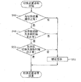
Fig. 2 and 3 are flowcharts showing the steps of the self-diagnosis at the time of startup. Here, items that can be diagnosed without using power storage device 30 and items that can be diagnosed for a power storage device in a state where power storage device breaker 50 is in a disconnected state are referred to as peripheral diagnostic items. The step of the self-diagnosis at startup shown in fig. 2 is a diagnostic step of peripheral diagnostic items. The step of the self-diagnosis at the time of startup shown in fig. 3 is a step of diagnosing the charge/discharge switching device 60 by setting the power storage device breaker 50 in a connected state when the result of the diagnosis of the peripheral diagnostic items is normal, and is also a step of diagnosing the power storage device in a used state. The reason why the peripheral diagnosis items are diagnosed before the other items is that: if a diagnosis using power storage device 30 is made without detecting an abnormality in a component that can be diagnosed without using the power storage device and power storage device breaker 50, unexpected overcharge, overdischarge, or overcurrent may occur in power storage device 30, which may damage power storage device 30.
First, description is made based on fig. 2. When the power storage system 10 is started, the integrated operation program of the power storage system starts to operate. In the integrated operation program of the power storage system, the first operation is started by a self-diagnosis program at the time of startup. First, initialization is performed (S10). Each component of power storage system 10 is set to an initial state by initialization. For example, switching device 20 is set to the series connection state, and power storage device breaker 50 is set to the disconnection state. The initialization processing is executed by the initialization setting unit of the self-diagnosis device 90 at the time of startup.
After the initialization is completed, a subroutine (sub-routine) for monitoring the power storage device breaker 50 for the open state in the initial state is started (S12). After S12, during the step of self-diagnosis at the time of activation, a subroutine program for monitoring the load side breaker 26 to be in the open state is activated (S14). After S14, the AC/DC converter 24 can normally communicate with the self-diagnosis device 90 at the time of startup, and a converter diagnosis is performed to diagnose whether or not to operate in accordance with the command (S16). After S16, when the switching device 20 is set to the initial state, the switching device 20 can normally communicate with the self-diagnostic device 90 at the time of activation, and a diagnosis is made as to whether or not the switching device is operating in accordance with the command (S1). After S18, the power storage device 30 can normally communicate with the self-diagnosis device 90 at the time of startup to diagnose the power storage device and whether or not the internal state of each battery pack 32, 32-2, 34-2, 36-2 constituting the power storage device 30 is obtained (S20).
The diagnostic processing steps of the peripheral diagnostic items are performed by the peripheral item diagnostic unit of the self-diagnostic device 90 at the time of activation. Here, S12 and S14 may be exchanged, and S16 and S18 may be exchanged. Each diagnosis is executed in further detail by a subroutine, and the contents of these are described later with reference to fig. 4 to 8.
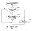
If the diagnosis result of the peripheral diagnosis item is normal, the procedure proceeds to the step of fig. 3. Fig. 3 is explained below.
First, the subroutine started in S12 is stopped (S21), and a state in which the power storage device breaker 50 can be connected is displayed on the display unit 82 (S22). This display is a display for urging the user to perform the operation of connecting power storage device breaker 50.
When the user sets power storage device breaker 50 in the connected state (S24), the user detects this and proceeds to the next diagnosis of charge/discharge switching device 60. Since S24 is not a step executed by the self-diagnosis device 90 at the time of startup, the frame indicating S24 is a dashed line frame in fig. 3 to distinguish it from frames indicating other steps.
The diagnosis of the charge/discharge switching device (S26) is performed to diagnose whether or not the charge switch 70 and the discharge switch 74 operate in accordance with a command in a normal communication with the self-diagnosis device 90 at the time of startup, with the power storage device breaker 50 in a connected state.
When the result of the diagnosis of the charge/discharge switching device (S26) is normal, the subroutine started in S14 is stopped (S27), and a state in which the load-side breaker 26 can be connected is displayed on the display unit 82 (S28). This display is a display for urging a user to perform a connection operation of the load side breaker 26.
When the user sets load-side breaker 26 to the connected state (S29), this is detected, and the self-diagnosis at startup is ended, so that power storage system 10 enters the operating state. From S21 to S29 are diagnostic processing steps in the use state of the power storage device 30, which are executed by the use state diagnostic unit of the self-diagnostic device 90 at the time of startup.
The periodic monitoring in the operating state is performed by the periodic monitoring device 110, and the content thereof will be described later.
The above is the step of the self-diagnosis at the time of startup, and the details of the specific diagnosis are described in detail with reference to fig. 4 to 12.
Fig. 4 is a diagram showing the detailed steps of the subroutine started in S12.
In the monitoring of whether or not the power storage device breaker 50 is in the open state executed in the subroutine started in S12, it is determined whether or not there is a stop instruction for stopping the monitoring of whether or not the power storage device breaker 50 is in the open state during the diagnostic step of the peripheral diagnostic items (S29). That is, the monitoring of the disconnection of power storage device breaker 50 is continued while the peripheral diagnostic items are diagnosed. The monitoring of whether or not the power storage device breaker 50 is in the open state monitors the respective breakers 52, 54, 56 constituting the power storage device breaker 50 in the open state (S30). The monitoring at S30 is performed by observing whether or not the state signal transmitted from each of the circuit breakers 52, 54, 56 to the self-diagnostic device 90 at the time of activation through the signal line is in the open state.
The initial state of the electrical storage device breaker 50 is the broken state as described above. Thus, if the connection state is detected, the self-diagnosis device 90 at the time of activation transmits a disconnection command to the corresponding breaker (S32). Accordingly, power storage device breaker 50 is in the open state. Monitoring continues if an open circuit condition is detected. The connected power storage device breaker is immediately opened, and thus, it is possible to continue the peripheral item diagnosis procedure while suppressing damage to the power storage device 30 due to unexpected overcharge, overdischarge, or overcurrent.
The processing steps of the subroutine started in S12 are executed by the state monitoring unit 92 of the power storage device breaker of the self-diagnosis device 90 at the time of startup.
Fig. 5 is a diagram showing the detailed steps of the subroutine started in S14.
The subroutine started in S14 is substantially the same as the subroutine of S12, but the point where the load side breaker 26 is constituted by 1 breaker and the point where the load side breaker 26 is manual, and the state of the load side breaker 26 cannot be changed from the side of the self-diagnosis device 90 at the time of starting, are different.
The monitoring of whether or not the load side breaker 26 is in the broken state is performed by determining whether or not there is a stop instruction to stop monitoring of whether or not the load side breaker 26 is in the broken state during the self-diagnosis at the time of activation (S33). That is, the monitoring of whether or not the load-side breaker 26 is in the open state is continued while the self-diagnosis at the time of starting is performed. The monitoring of whether or not the load side breaker 26 is in the broken state (S34) is performed by observing whether or not the state signal transmitted from the self-diagnostic device 90 at the time of starting the load side breaker 26 via the signal line pair indicates the broken state.
The load side breaker 26 is a manual type, and therefore does not have a function of receiving a command from the self-diagnosis device 90 at the time of activation. Thus, if the user manually performs the switching operation and detects the connected state, the error lamp 86 is turned on to display an error on the display unit 82 (S36), and the load-side breaker diagnosis is ended.
The processing steps of the subroutine started in S14 are executed by the state monitoring unit 94 of the load side breaker of the self-diagnosis apparatus 90 at the time of starting.
Fig. 6 is a diagram showing the detailed procedure of the converter diagnosis at S16.
In S16, it is first diagnosed whether or not communication between the AC/DC converter 24 and the self-diagnosis device 90 at the time of startup is normally performed (S38). Specifically, the diagnosis is made by whether or not there is a response when a command is sent from the self-diagnosis device 90 at the time of startup to the AC/DC converter 24. When the communication is normal, it is diagnosed whether or not the AC/DC converter 24 operates in accordance with the command.
As the operation command, an off command and an on command are issued, and whether or not the respective outputs are normal is diagnosed. Specifically, when the AC/DC converter 24 is instructed to turn off, the discharge-side current/voltage detection unit 76 checks that the output voltage is not outputted from the AC/DC converter 24 (S40). When an on command is given to the AC/DC converter 24, the current/voltage detection unit 76 on the discharge side confirms that the output voltage is output from the AC/DC converter 24 (S42).
If the results of S40 and S42 following S38 are normal, the AC/DC converter 24 is set as a normal state, the converter diagnosis is ended, and the process proceeds to the next step. If the result of any of the processes is abnormal, the error lamp 86 is turned on to display an error on the display unit 82 (S44), and the converter diagnosis is terminated. The processing step of the converter diagnosis at S16 is executed by the converter diagnosis section 96 of the self-diagnosis device 90 at the time of startup.
Fig. 7 is a diagram showing the detailed procedure of the diagnosis of the switching device of S18 performed when the result of the converter diagnosis of S16 is normal.
In S18, first, it is diagnosed whether or not the communication between the switching device 20 and the self-diagnostic device 90 at the time of activation can be normally performed (S46). Specifically, the diagnosis is performed by whether or not a response is made when the self-diagnosis device 90 at the time of activation transmits a command for inquiring the connection method to the switching device 20. When the communication is normal, it is then diagnosed whether or not the switching unit 20 operates in accordance with the command.
As the operation command, a series connection command and a parallel connection command are issued, and whether or not the output for each connection command is normal is diagnosed. Since the initial state of the switching device 20 is the series connection state, a parallel connection command is given to the switching device 20 to diagnose whether or not the series connection state is changed to the parallel connection state. Specifically, whether or not the output is normal is confirmed by the voltage value in the current/voltage detection unit 72 on the charging side (S48). For example, when the series connection state is changed to the parallel connection state in a clear day, the photoelectric conversion module 14 and the charge/discharge switching device 60 are electrically connected, and the output voltage of the photoelectric conversion module 14 is detected by the current/voltage detection unit 72 on the charging side. That is, the output voltage of the photoelectric conversion module 14 changes from 0V to, for example, about 120V. In this way, by detecting the voltage value in the current/voltage detection unit 72 on the charging side, it is diagnosed whether or not the operation with respect to the parallel connection command is normal.
Next, a series connection command is given to the switching device 20, and whether or not the output is normal is checked based on the voltage value in the current/voltage detection unit 72 on the charging side, thereby determining whether or not the parallel connection state is changed to the series connection state (S50). In this case, when the parallel connection state is changed to the series connection state, the photoelectric conversion module 14 and the charge/discharge switching device 60 are electrically disconnected, and therefore, the voltage value in the current/voltage detection unit 72 on the charging side becomes 0V. In this way, it is confirmed that the voltage value in the current/voltage detection unit 72 on the charging side becomes 0V, and it is diagnosed whether or not the operation with respect to the series connection command is normal. In addition, if the vehicle is in the daytime, it can be determined whether the operation is normal by the change in the voltage value as described above, and if the vehicle is in the nighttime, it is difficult to diagnose the switching device. Thus, for example, the following may be provided: an illuminance meter is provided, and it is determined whether or not the illuminance is nighttime (whether or not light irradiation is possible to generate power) based on the measured illuminance, and if it is determined that power generation is not possible, the diagnosis is skipped.
If the results of S48 and S50 following S46 are normal, the switch device 20 is set as the normal state, the diagnosis of the switch device is ended, and the next step is proceeded to. If any of the processing results indicates an abnormal state, the error lamp 86 is turned on to display an error on the display unit 82 (S52), and the switching device diagnosis is terminated. These processing steps are executed by the switching device diagnosing section 98 of the self-diagnostic device 90 at the time of startup.
Fig. 8 is a diagram showing the detailed procedure of the power storage device diagnosis of S20 performed next when the diagnosis result of the switching device is normal.
First, an operating power supply is supplied to a sensor or the like of power storage device 30 (S54). That is, electric power of, for example, 12V is supplied from the side of the self-diagnosis device 90 at the time of startup to the side of the power storage device 30. This operation power supply is performed for each of the battery state detection units 38, 38-2, 40-2, 42, and 42-2 of the battery packs.
Thereafter, it is diagnosed whether or not the communication between the power storage device 30 and the self-diagnosis device 90 at the time of startup is normally performed (S56). Specifically, the self-diagnosis device 90 at the time of startup diagnoses whether or not there is a response when a command is sent from the battery state detection units 38, 38-2, 40-2, 42-2 of each battery pack. Further, as shown in fig. 1, by connecting the communication lines of the battery packs connected in series and providing the communication lines with the self-diagnosis device 90 at the time of activation for each parallel connection, the self-diagnosis device 90 at the time of activation can know not only the number of battery packs constituting the power storage device 30 but also the number of parallel connections and the number of series connections for each parallel connection based on the execution of communication. In this way, the configuration of power storage device 30 can be grasped by communication, and the possibility of occurrence of an overcurrent can be suppressed.
When the communication is normal, it is then diagnosed whether or not the characteristics of the battery packs 32, 32-2, 34-2, 36-2 constituting the power storage device 30 are within the normal range, and whether or not an abnormal state such as a sensor abnormality, an overcurrent, an overdischarge, an overcharge, or the like is detected as the internal state of the battery packs (S58). The diagnosis is made based on the detection data of the battery state detection units 38, 38-2, 40-2, 42-2 corresponding to the battery packs 32, 32-2, 34-2, 36-2 and the internal state data. That is, when the output voltage of each battery pack, the internal temperature of the battery pack, and the like are within predetermined normal ranges, the output voltage and the internal temperature of the battery pack are diagnosed as normal, and when the output voltage and the internal temperature of the battery pack are out of the normal ranges, the output voltage and the internal temperature of the battery pack are diagnosed as abnormal. As the internal state of the battery pack, it is determined that the battery pack is normal when an abnormal state such as a sensor abnormality, overcurrent, overdischarge, or overcharge is not detected, and is determined that the battery pack is abnormal when an abnormal state is detected.
If the result of S58 following S56 is normal, the power storage device 30 as a whole is in a normal state, regular monitoring of the power storage device is started (S59), diagnosis of the power storage device is ended, and the process proceeds to the next step. If any of the processing results indicates an abnormal state, the error lamp 86 is turned on to display an error on the display unit 82 (S60), and the diagnosis of the power storage device is ended. The regular monitoring of the power storage device is performed periodically, for example, at 1 second intervals until the self-diagnosis at the time of startup is completed. That is, referring to fig. 8a, it is determined whether self-diagnosis at the time of startup is completed (S59-1), and if not, it is diagnosed whether the characteristics of each battery pack 32, 32-2, 34-2, 36-2 constituting the power storage device 30 are in a normal range, and an abnormal state such as sensor abnormality, overcurrent, overdischarge, overcharge, or the like is detected as the internal state of the battery pack (S59-2). When an abnormal state such as a sensor abnormality, overcurrent, overdischarge, or overcharge is not detected as the internal state of the battery pack, it is diagnosed as normal, and when an abnormal state is detected, it is diagnosed as abnormal, the error lamp 86 is turned on, an error display is made on the display unit 82 (S59-3), and then the regular monitoring of the power storage device is terminated. These processing steps are executed by the power storage device diagnosis unit 100 of the self-diagnosis device 90 at the time of startup.
By regular monitoring of the power storage device, even if unexpected overcharge, overdischarge, or overcurrent occurs in the power storage device 30 in a diagnosis using the power storage device 30 described later, damage to the power storage device 30 can be prevented.
Fig. 9 is a diagram showing the detailed procedure of the diagnosis (S26) of the charge/discharge switching device performed when the user sets the power storage device breaker 50 to the connected state (S24). Here, whether or not the on/off operations of the charge switch 70 and the discharge switch 74 are normal is diagnosed.
First, it is diagnosed whether or not the on operation of the charge switch 70 is normal (S62). Here, an on command is given to the charge switch 70, and the charge switch 70 is turned on. Next, the voltage value of the current/voltage detection unit 72 on the charging side is compared with the voltage values of the current/ voltage detection units 62, 64, and 66 on the power storage device side, and if the voltage difference during this period is within a predetermined range, it is determined that the on operation is normal. If a voltage difference exceeding a predetermined range exists despite the on state, it is determined to be abnormal (open circuit).
Next, it is diagnosed whether or not the off operation of the charge switch 70 is normal (S64). Here, an off command is given to the charge switch 70, and the charge switch 70 is turned off. Next, if the current value of the charging-side current/voltage detection unit 72 or the current value of the power storage device-side current/ voltage detection units 62, 64, and 66 is within the measurement error range of 0A, it is determined that the turn-off operation is normal. When the current flowing from the photoelectric conversion module 14 is detected despite the off state, it is determined to be abnormal (short-circuited).
Similarly to S62, it is diagnosed whether or not the on operation of discharge switch 74 is normal (S66). Here, an on command is given to the discharge switch 74, and the discharge switch 74 is turned on. Next, the voltage value of the discharge-side current/voltage detection unit 76 and the voltage values of the power storage device-side current/ voltage detection units 62, 64, and 66 are compared, and if the voltage difference during this period falls within a predetermined range, it is determined that the on operation is normal. If a voltage difference exceeding a predetermined range exists despite the on state, it is determined to be abnormal (open circuit).
Similarly to S64, it is diagnosed whether or not the opening operation of the discharge switch 74 is normal (S68). Here, an off command is given to the discharge switch 74, and the discharge switch 74 is turned off. Next, if the voltage value of the discharge-side current/voltage detection unit 76 is within the measurement error range of 0V, it is determined that the off operation is normal. In spite of the off state, it is determined that the voltage of power storage device 30 is detected as abnormal (short-circuited). The reason why the determination is made not by the current value but by the voltage value is that no current flows because the load-side breaker 26 is interrupted.
The processing sequence of S62 and S64 may be the reverse of the processing sequence of S66 and S68.
If these results are normal, the charge/discharge switching device 60 is in a normal state, and the diagnosis of the charge/discharge switching device is ended, and the process proceeds to the next step. If any of the processing results indicates an abnormality, the error lamp 86 is turned on to display an error on the display unit 82 (S70), and the diagnosis of the charge/discharge switching device is ended. These processing steps are executed by the switch diagnosis unit 102 of the self-diagnosis device 90 at the time of startup.
When the diagnostic result of the charge/discharge switching device 60 is normal, the interruption monitoring of the load-side breaker 26 is stopped (S27), the load-side breaker connectable display is displayed (S28), the user sets the load-side breaker 26 to the connected state (S29), and when this is detected, the self-diagnosis at the time of starting is completed.
In the self-diagnosis at the time of startup, when an abnormality is detected, an error display is performed by a state monitoring unit and each diagnostic unit of the load-side breaker. Next, for example, the power storage device breaker 50 is turned off, an abnormality completion timing for returning each component of the power storage system 10 to the initial state is executed, and self-diagnosis at the time of startup is completed.
Fig. 10 is a diagram showing the display screen of the display unit 82 in S22 of fig. 3. In this way, the display is notified that power storage device breaker 50 is in a connectable state, and a character for urging the user to connect power storage device breaker 50 is displayed.
Fig. 11 is a diagram showing the display screen of the display unit 82 in S28 of fig. 3. In this way, the display is notified that the load side breaker 26 is in the connectable state, and a character for urging the user to connect the load side breaker 26 is displayed.
Fig. 12 is a diagram showing a display screen of the display unit 82 when an error display is performed. Here, since an abnormality is detected in the self-diagnosis at the time of startup, first, a character of turning off the power supply can be displayed with attention. In the column of the error display in 2 lines below the character, since the display section 82 is a small-sized display, for example, a plurality of error displays can be sequentially displayed on the display screen by using a left and right key, not shown, in such a manner that the next error display is performed when the left key is pressed once and the first 1 error display is performed when the right key is pressed once.
The error display can represent a plurality of contents in an alphanumeric combination.
In fig. 12, a and B are used to distinguish the timing at which an abnormality occurs, where a denotes a factor that causes an abnormal end in the step of self-diagnosis at the time of startup, and B denotes a factor that causes an abnormality again when the abnormal end timing is executed. As an example of B, there is an abnormality that occurs when the system cannot be returned to the initial state, such as when the on/off of the charge switch 70 or the discharge switch 74 cannot be confirmed. A. B can be selected by a cursor at the left end of the screen. With regard to the selected timing, a plurality of error displays can be sequentially displayed by the left and right keys described above. Needless to say, in order to distinguish timings other than this, display such as A, B can be used.
A. The 2-bit number following B is the consecutive number of errors. The next 2 digits after "/" are the total number of total errors as a whole. Therefore, a01/03 indicates that 3 errors, the content of the 1 st error thereof, were detected in the self-diagnosis at startup.
The combination of the next 2-bit, and 3-bit numbers of 7 bits in total indicates the content of the error. The first 2 bits indicate the type of device to be diagnosed, the second 2 bits indicate the number of differences when there are more devices to be diagnosed in the device to be diagnosed, and the last 3 bits indicate error codes. For example, regarding the first 2 bits, 01 may be associated with the converter, 02 with the switching device, 03 with the power storage device, and the like. In this way, when the error content is expressed, in fig. 12, 03-11-003, the first 03 indicates the power storage device, the second 11 indicates the 1 st (parallel number) -1 st (series number) battery pack in the power storage device, and the last 003 indicates, for example, a communication error indicated by the error code 003.
The above is an example used in the description of the error display, and error display methods other than this can be used. The wordings of fig. 10, 11, and 12 are examples, and other expressions may be used, or a language other than japanese, such as english, may be displayed based on the specification of the display.
The self-diagnosis device 90 at the time of startup is explained above, and the periodic monitoring device 110 is explained next with reference to fig. 13 and 14. The periodic monitoring device 110 has a function of periodically monitoring whether or not each component of the power storage system 10 is in a normal state in the operating state after the power storage system 10 has entered the operating state while being normal in the self-diagnosis at the time of startup. The timing for performing the periodic monitoring can be determined in advance. For example, the setting may be performed at intervals of 1 second, or may be performed for each predetermined state of charge of power storage device 30.
Fig. 13 is a flowchart for explaining processing steps at the time of normal operation following the step of self-diagnosis at the time of startup.
When the operation state is entered, the respective components of the power storage system 10 are periodically monitored for normality at monitoring intervals set in advance (S86). That is, the regular monitoring in this case is performed in a state where both the power storage device breaker 50 and the load side breaker 26 are connected, unlike the regular monitoring in S59. In the above-described periodic monitoring, the characteristics and internal state of power storage device 30 are periodically monitored, as in S59 for periodic monitoring of the power storage device at the time of self-diagnosis at the time of startup.
When an abnormality is detected as a result of the periodic monitoring (S88), the detected abnormal state is classified into a failure state in which early recovery cannot be expected or a recoverable abnormal state based on a predetermined classification criterion. This process is executed by the detection abnormality classification unit 112 of the periodic monitoring device 110.
Based on this classification, it is determined whether or not the detected abnormal state is a failure state in which early recovery is not expected (S90), and when the detected abnormal state is classified as a failure state in which early recovery is not expected, the power storage device breaker 50 is opened (S92), an abnormal end timing for returning the system to the initial state is executed (S96), and an alarm is output (S98), and the normal operation is ended. This process is executed by the failure state processing unit 114 of the periodic monitoring apparatus 110. When the detected abnormal state is classified as a recoverable abnormal state, appropriate abnormality coping processing such as charge/discharge, or temporary stop of charge is performed in accordance with the detected abnormal state (S100), and an alarm is output (S94). The alarm output is that the error lamp 86 is turned on and an error message is displayed on the display unit 82. This process is executed by the abnormal state processing unit 116 of the periodic monitoring apparatus 110.
In this way, when an abnormality is detected by periodic monitoring, the operation of the power storage system 10 is not stopped as a failure uniformly, but is classified into a recoverable abnormal state and a failure state in which rapid recovery cannot be expected. This is because the operating rate of power storage system 10 can be increased by appropriate countermeasure against an abnormality. The recoverable abnormal state may be divided into a plurality of stages according to the recoverable time or the like, such as the abnormal state 1, the abnormal state 2, and the abnormal state 3, or may be divided according to the abnormality handling process.
Fig. 14 is a diagram showing an example of classification criteria relating to detection of an abnormality. Here, the abnormality determination condition is indicated for each monitoring target, and each abnormality determination condition indicates whether the detected abnormality is a failure state in which early recovery is not expected or an abnormality state in which recovery is possible. Classification criteria related to the detected abnormality are stored in advance in the storage unit of the periodic monitoring apparatus 110. The classification criteria related to the detected abnormality may be stored in a hierarchical lookup table as shown in fig. 14, or may be stored in a form in which a search keyword is input by using a hierarchical structure, and thereby a failure state in which early recovery is not expected, a recoverable abnormality state, a simple graph form, or the like is output.
As is apparent from observation of items of periodic monitoring of power storage device 30 in fig. 14, when the battery state is over-discharge, over-charge, or abnormal in battery temperature, these are failure states in which early recovery is not expected. On the other hand, the battery state is a recoverable abnormal state when fully charged. The system is in an abnormal state because the system performs charge/discharge control in a range where the system does not become fully charged depending on the state of charge of the power storage device 30, although the system is not in an abnormal state. Since there is no possibility of damage to power storage device 30, it is set to a recoverable abnormal state. Regarding overcharge and overdischarge, since the state is abnormal in the power storage device 30, not only is there a high possibility of damage to the power storage device 30, but also, from the viewpoint of system safety, an early response is required, and therefore, a failure state is assumed in which early recovery from system disconnection of the power storage device 30 is not expected due to disconnection of the power storage device breaker 50.
Further, it is understood from the observation of the items of the periodic monitoring of the charge/discharge switching device 60 that the abnormality of the charge current value and the abnormality of the discharge current value are recoverable abnormal states, but if the abnormal states continue for a predetermined time or longer, the abnormal states become a failure state in which early recovery is not expected. This is because the charging current value and the discharging current value may become large values instantaneously, and therefore recovery is possible, but if the charging current value and the discharging current value continue for a long time, there is a possibility that power storage device 30 may be damaged.
In addition, the state in which the charge switch 70 or the discharge switch 74 constituting the charge/discharge switching device 60 is not normally operated in response to a predetermined operation instruction is set to a failure state in which early recovery cannot be expected. This is due to: the state in which the control is not performed for charging or discharging power storage device 30 is highly likely to cause damage to power storage device 30 if it is left as it is.
In this way, the state in which an abnormality is detected is not uniformly classified as a failure state, and the state that can be recovered is not classified in detail according to the contents of the abnormality, whereby the operation rate of power storage system 10 can be improved. On the other hand, by setting the power storage device breaker 50 to the open state while the power storage device 30 is in the failure state in which early recovery cannot be expected, the power storage device 30 can be protected.
The self-diagnosis at the time of the start-up is described as the diagnosis of the charge/discharge switching device at S26, with the power storage device breaker 50 in the connected state and the load-side breaker 26 in the disconnected state. In many power storage systems, the load-side breaker 26 is provided between the discharge switch 74 and the load, but depending on the case, there is also a power storage system in which an inverter or a DC/DC converter is directly connected to the discharge switch 74. In this case, even when the discharge switch 74 is turned off, the discharge switch 74 appears to be turned on at first glance because the primary-side capacitor of the input-side capacitance of the inverter or the DC/DC converter is charged and a voltage is applied to the load side of the discharge switch 74. Hereinafter, a discharge switch diagnosis that does not make an erroneous determination even if the load-side breaker 26 is not provided will be described.
Fig. 15 is a view obtained by extracting the periphery of the discharge switch 74 from the overall configuration diagram of fig. 1. The current/voltage detecting unit 76 on the discharge side detects the current I flowing through the discharge switch 7474Current detector for detecting voltage V to load side terminal of discharge switch 7474A voltage detector for detecting the voltage. Similarly, the current/ voltage detection units 62, 64, and 66 on the power storage device side are each composed of a current detector and a voltage detector, and the current/voltage detection units are collectively referred to as a current I flowing from the power storage device 30 to the discharge switch 7430Current detector for detection, voltage V to power storage device side terminal of discharge switch 7430And a voltage detector for detecting the voltage. Further, an on command and an off command for the discharge switch 74 are transmitted from the switch diagnostic unit 102.
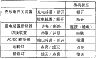
Fig. 16 is a diagram showing a case where it is determined whether the operation of the discharge switch 74 is normal or abnormal, which is classified into 3 types. Here, first, the self-diagnosis at the time of starting the power storage system and the periodic monitoring at the time of operating the power storage system are classified into 2 types, and the former is further classified into: there are a case where a load-side breaker is present and the DC/DC converter is in a disconnected state, and a case where a load-side breaker is not provided and the DC/DC converter is always connected to the discharge switch 74. Next, a configuration diagram of the periphery of the discharge switch 74 in each case is shown with reference to fig. 15, and regarding each case, the operation determination and the off command are given when the on command is given to the discharge switch 74The operation judgment in the case (2) is made by integrating I of the current detector74And V of the voltage detector30、V74Is the situation of how the detection result of (2) is utilized.
In the self-diagnosis at the time of startup, as to the case where the load side breaker 26 is provided and is in the broken state, it is the same as that already described in association with fig. 9. That is, the diagnosis as to whether the on operation of the discharge switch 74 is normal or not is performed by giving an on command to the discharge switch 74 to turn the discharge switch 74 on, and then comparing the voltage value of the current/voltage detection unit 76 on the discharge side with the voltage values of the current/ voltage detection units 62, 64, and 66 on the power storage device side, and determining that the on operation is normal if the voltage difference therebetween is within a predetermined range. If the voltage difference exceeds a predetermined range although the voltage difference is in the on state, it is determined that the voltage difference is abnormal (open circuit).
The diagnosis as to whether or not the off operation of the discharge switch 74 is normal is performed by giving an off command to the discharge switch 74 to turn off the discharge switch 74, and then determining that the off operation is normal if the voltage value of the discharge-side current/voltage detection unit 76 is within the measurement error range of 0V. When the voltage of power storage device 30 is detected despite the off state, it is determined that there is an abnormality (short circuit). The reason why the determination is made as the voltage value without using the current value is that the load-side breaker 26 side is interrupted and no current flows.
In the self-diagnosis at the time of startup in fig. 16, when the load-side breaker 26 is not provided, the determination of the on operation of the discharge switch 74 is the same as that when the load-side breaker 26 is provided. However, the determination as to whether or not the opening operation of the discharge switch 74 is normal is different from the case where the load-side breaker 26 is provided. This is because, when the load-side breaker 26 is not provided, the discharge switch 74 is directly connected to the DC/DC converter 28, and the voltage detector sets the voltage state of the input-side capacitor as V74And the detection is performed. I.e. to dischargeWhen the switch 74 gives an on command, a current is supplied to the DC load 18 via the DC/DC converter 28. Thereby, the input side capacitance of the DC/DC converter 28 is charged to have V30The voltage of (c).
When the discharge switch 74 is given an off command, the supply of current to the DC/DC converter 28 is stopped, and the input side capacitor continues to hold V as long as it is not discharged30The voltage of (c). In the case of a load-side breaker 26, e.g. V74=V30If the load-side breaker 26 is not provided, even if V is abnormal, it can be judged that the discharge switch 74 is abnormal in the opening operation74=V30It cannot be determined that the opening operation of the discharge switch 74 is abnormal. Here, I is observed74,I74When the current flows, it can be determined that the opening operation of the discharge switch 74 is abnormal.
Fig. 17 is a flowchart showing a procedure of determining whether the off operation of the discharge switch 74 is normal or abnormal in the self-diagnosis at the time of startup. First, it is judged whether or not V is present74=V30That is, it is determined whether or not there is no voltage difference between both terminals of the discharge switch 74 (S110). When the judgment result is "no", the opening operation of the discharge switch 74 is normal (Sl 16). When judged as "YES", judgment I is made next74If the current exceeds a predetermined range, for example, if the current is not 0, that is, if the load current flows through the discharge switch 74 is determined (Sl 12). Here, the judgment result is "NO", and it is within a predetermined range, for example, I74When the value is 0, it is determined that the opening operation of the discharge switch 74 is normal (Sl 16). When the determination is yes and the load current flows, it is determined that the opening operation of the discharge switch 74 is abnormal (Sl 14).
Thus, the opening operation of the discharge switch 74 can be set to V74=V30Condition (2) and I74When the condition other than 0 is combined in an AND relationship, it can be determined that the abnormality is present. Compare it with the case where the load-side breaker 26 is provided, while using the pair I74This is different for the current detector that performs the detection. I.e. at the installation of a loadIn the case of the side breaker 26, only the pair V is used74、V30The voltage detector for detection can determine whether the opening operation of the discharge switch 74 is normal or abnormal, and when the load-side breaker 26 is not provided, the detection result of the current detector needs to be used in combination.
However, the steps shown in fig. 17 can also be used in the case where the load-side breaker 26 is provided. Although the step of Sl12 is added, no misjudgment occurs. Therefore, the steps of fig. 17 are preferably used regardless of the presence of the load-side breaker 26.
Since Sl12 is an extra step originally in the case of the load-side breaker 26, the Sl12 step can be omitted in the case of the load-side breaker 26 by the selection of the user.
Thus, the discharge switch 74 is turned off at I74Condition of 0 and not V74=V30The condition (2) is combined in an AND mode, AND whether the condition is normal or not can be judged. The steps of fig. 17 can also be adapted to the case where there is a load-side breaker 26.
Referring back to fig. 16 again, when the power storage system is in operation and periodic monitoring is performed, I of the load current can be used74The monitoring is performed to determine whether the opening operation of the discharge switch 74 is normal or abnormal. In addition, the on operation of the discharge switch 74 can be performed by V detected by the voltage detector in the same manner as described above74、V30Making a comparison of V74And V30When the voltage difference is within a predetermined range, the judgment is normal, and when the voltage difference is beyond the predetermined range, the judgment is abnormal.
Comparing the operation diagnosis of the discharge switch under the periodic monitoring during the operation with the operation diagnosis of the discharge switch under the self-diagnosis at the time of starting is known that: in the self-diagnosis at the time of startup, steps different from the periodic monitoring in the action need to be taken. That is, in the case of periodic monitoring during operation, the operation diagnosis of the discharge switch 74 can be performed only by using the detection result of the current detector, but in the self-diagnosis at the time of startup, it is necessary to prevent erroneous determination regardless of the configuration of the power storage system by combining the detection result of the voltage detector and the detection result of the current detector.
Next, the contents of the operation control device 120 will be described with reference to fig. 18 to 22. Operation control device 120 has a function of setting load-side breaker 26 and power storage device breaker 50 in a standby state without being in a disconnected state when the operation of power storage system 10 is stopped. That is, operation control device 120 has, as the operation mode, a normal operation mode in which actual charge/discharge control is performed on power storage system 10, and a standby mode in which actual charge/discharge control is prohibited from being performed on power storage system 10 and the other modes are the same as those in the normal operation mode.
Fig. 18 is a diagram for explaining the state of the normal operation mode 130 and the state of the standby mode 140, and the state transition 150 therebetween. Fig. 19 shows the setting conditions of the normal operation mode, and fig. 20 shows the setting conditions of the standby mode.
The normal operation mode 130 includes 3 types, i.e., a basic state 132, a failure state 134, and a recoverable abnormal state 136. The state transition from the basic state 132 to the failure state 134 or the recoverable abnormal state 136 is performed when an abnormality is detected by periodic monitoring performed by the periodic monitoring apparatus 110. When an abnormality is detected by periodic monitoring, the abnormality is classified into a failure state 134 or a recoverable abnormality state 136 based on a classification criterion relating to the detected abnormality as shown in fig. 14. In the case of the failure state 134, the state is not directly returned to the basic state 132, but the recoverable abnormal state 136 is returned to the basic state 132 when the abnormal state is resolved and the normal state is achieved.
In a basic state 132 of the normal operation mode 130 of fig. 18, a state transition under charge and discharge control is shown. Here, the state transition between 3 states, that is, a charge/discharge state in which both charge and discharge are performed, a discharge state in which only discharge is performed without charge, and a charge state in which only charge is performed without discharge, is shown in accordance with the state of charge of power storage device 30. As the state of charge of power storage device 30, SOC can be used. For example, when the SOC is 90% or more in the charge/discharge state, the state transition is made to the discharge-only state, and when the SOC is less than 40%, the state transition is made to the charge-only state. When the SOC is less than 60% in the discharge-only state, the state transition is made to the charge/discharge state, and when the SOC is 60% or more in the charge-advance state, the state transition is made to the charge/discharge state. Although power storage device 30 can be charged to SOC 100%, a state of charge close to 100% may shorten the life of the battery pack constituting power storage device 30. In the present embodiment, charging is stopped until SOC 90% and only discharging is performed. Similarly, since there is a possibility that the life of the battery pack is shortened by discharging until the SOC becomes close to 0%, if the SOC becomes less than 40%, the battery pack is charged only without discharging more than that. Next, the battery pack can operate most efficiently in the vicinity of SOC 60%, and therefore, this is set as the charge/discharge state transition threshold. The above is an example for explanation, and other SOC values may be used as the state transition condition.
The state of the standby mode 140 in fig. 18 is substantially the same as that in the normal operation mode 130, and is different from the state in which the basic state 132 of the normal operation mode 130 is changed to the standby state 142. However, the state transition in the standby state 142 is the same as the state transition in the basic state 132 of the normal operation mode 130. That is, when the SOC becomes 90% or more in the charge/discharge state, the state transition is made to the discharge-only state, and when the SOC becomes less than 40%, the state transition is made to the charge-only state. When the SOC is less than 60% in the discharge-only state, the state is changed to the charge/discharge state, and when the SOC is 60% or more in the charge-only state, the state is changed to the charge/discharge state.
In this way, both the basic state 132 in the normal operation mode 130 and the standby state 142 in the standby mode 140 are controlled with the same SOC reference as the condition for causing the state transition. In the basic state 132 of the normal operation mode 130, the charge control and the discharge control are actually performed in the charge/discharge state, the discharge control is actually performed in the discharge-only state, and the charge control is actually performed in the charge-only state, whereas in the standby state 142 of the standby mode 140, the charge/discharge is prohibited in any state.
Therefore, in the standby mode 140, the operation mode is fixed according to the SOC when switching from the normal operation mode 130 to the standby mode 140, and the actual states of the components of the power storage system 10 are not always maintained in a fixed state during the standby mode 140, and therefore, various state transitions may occur during the standby mode 140. For example, if the SOC when switching to standby mode 140 is 61%, standby state 142 is only in a discharge state. Here, when the SOC is lowered to less than 60% for some reason while the standby mode 140 is continued for several hours, the state is changed to the charge/discharge state. When the SOC decreases to less than 40%, the state may transition to the state of charge only.
In this way, in the standby mode 140, although the operation of the charge/discharge switching device 60 is prohibited, the state of charge of the power storage device 30 is continuously monitored, and the state transition is performed based on the result. As described above, when the standby mode 140 is returned to the normal operation mode 130, the state of the standby state 142 is passed to the state of the basic state 132 as it is, and the charge and discharge control is immediately performed according to the state. In the above example, when the state is changed to the charge-only state in the standby state 142, such as when the normal operation mode 130 is returned, the charge-only control is immediately performed in accordance with not only the discharge-only state when the standby mode 140 is switched but also the current charge-only state.
Fig. 19 shows the setting conditions for the normal operation mode 130. Under the setting conditions, the operation mode of power storage system 10 is set to normal operation mode 130. This setting is performed by the normal operation mode setting unit 122 of the operation control device 120.
Fig. 20 shows the setting conditions when the standby mode 140 is set. Under the setting conditions, the operation mode of power storage system 10 is set to standby mode 140. This setting is performed by the standby mode setting unit 124 of the operation control device 120.
It is understood that in the standby mode 140, both the charge switch 70 and the discharge switch 74 are turned off, and the operation of the charge/discharge switching device 60 is prohibited during the standby mode 140. Therefore, the state transition 150 between the normal operation mode 130 and the standby mode 140 can be performed by changing the setting of the charge/discharge switching device 60 between the charge/discharge enable control and the charge/discharge prohibition control. The state transition 150 is executed by the state transition unit 126 of the operation control device 120.
In the standby mode 140, since the load-side breaker 26 and the power storage device breaker 50 are not in the disconnected state, the power storage device breaker diagnosis and the load-side breaker diagnosis in the self-diagnosis at the time of startup are not performed, and the normal operation mode 130 can be easily restored only by releasing the charge/discharge control prohibition.
As a specific example, when the charge/discharge control is performed on the power storage system 10 during daytime of operation of the office building and the operation of the power storage system 10 is stopped during night when the office building is not operating, there is an advantage in that a process of disconnecting the power storage device breaker 50 from the load side breaker 26 at night and reconnecting the power storage device breaker 50 to the load side breaker 26 in the next morning is omitted.
In such a case, the period discriminating unit of the operation control device 120 discriminates between the normal operation period during which the normal operation is performed and the charge/discharge stop period during which the charge/discharge is stopped, based on the charge/discharge schedule of the power storage system determined in advance. The state transition unit 126 can control the charge/discharge switching device 60 so that the state transition is performed from the normal operation mode 130 to the standby mode 140 when the charge/discharge stop period is acquired, and the state transition is performed from the standby mode 140 to the normal operation mode 130 when the normal operation period is acquired.
As another specific example of the standby mode 140, there are, for example: when the setting of the control parameter used for controlling the operation of the charge/discharge switching device 60 is changed, the setting of the control parameter is changed as the standby mode 140 without disconnecting the power storage device breaker 50 and the load-side breaker 26. When the setting change of the control parameter is completed, the normal operation mode 130 can be returned simply by releasing the charge/discharge control prohibition, and the operation under the new control parameter can be performed.
In such a case, it is possible to allow the setting of the control parameter to be changed when the charge/discharge switching device 60 is in the standby mode 140, with respect to the parameter setting unit for setting the control parameter used for the operation control, and to make a state transition from the standby mode 140 to the normal operation mode 130 when it is confirmed that the setting of the control parameter is changed. The parameter setting unit may be provided in the operation control device 120.
Fig. 21 and 22 are diagrams illustrating effects when standby mode 140 is used from the viewpoint of performance of power storage device 30. As described above, since the charge/discharge control of power storage device 30 is prohibited in standby mode 140, power storage device 30 does not experience a temperature increase due to charge/discharge. Therefore, the ambient temperature of power storage device 30 is lower than that during operation. This can be expected to extend the life of power storage device 30.
Fig. 21 is a diagram showing how the capacity of power storage device 30 decreases due to the storage temperature of power storage device 30 and the elapse of the storage time. Here, the initial SOC for storage is set to 75%, and the capacity ratio based on the SOC 75% shows the capacity decrease. Fig. 21 is a graph in which the horizontal axis represents 1/2 th power of the storage time, the vertical axis represents the capacity ratio, and the storage temperatures are 25 ℃ and 45 ℃ to compare the decrease in the capacity ratio. As shown in fig. 21, as the storage temperature is lower, the capacity of power storage device 30 decreases, and the life is longer.
Fig. 22 is a graph showing the results of the charge-discharge cycle test. The horizontal axis represents 1/2 th power of the number of cycles, and the vertical axis represents the capacity ratio. As shown in fig. 22, it can be seen that: the lower the test temperature, the smaller the decrease in the capacity of power storage device 30, and the longer the life.
Here, the charge-discharge cycle test was performed in the following manner. Namely, the temperature was set to 25 ℃ and 45 ℃. Next, as the charge/discharge conditions, as the charge conditions of the 1 st cycle, after constant current charging was performed for 4 hours at a current of 50mA, constant current charging was performed at a current of 200mA until the battery voltage became 4.20V, and constant voltage charging was performed at a voltage of 4.20V until the current value became 50 mA. Further, as the discharge condition of the 1 st cycle, discharge was performed at a constant current of 200mA until the battery voltage became 2.75V. As the charging conditions of the 2 nd cycle to the 500 th cycle, constant current charging was performed at a current of 1000mA until the battery voltage became 4.20V, and constant voltage charging was performed at a voltage of 4.20V until the current value became 50 mA. As the discharge conditions of the 2 nd to 500 th cycles, constant current discharge was performed at a current of 1000mA until the cell voltage became 2.75V. The relationship between the capacity ratio and the number of cycles was thus obtained.
Industrial applicability of the invention
The self-diagnosis device for the power storage system according to the present invention can be used for a power storage system including many components in addition to the power storage device.
Description of reference numerals:
10 an electricity storage system, 12 an external commercial power source, 14 a photoelectric conversion module, 16 an AC load, 18 a DC load, 20 a switching device, 22 an inverter, 24 an AC/DC converter, 26 a load side breaker, 28 a DC/DC converter, 30 an electricity storage device, 32-2, 34-2, 36-2 a battery pack, 38-2, 40-2, 42-2 a battery state detection portion, 50 an electricity storage device breaker, 52, 54, 56 a breaker, 60 a charge and discharge switching device, 62, 64, 66 an electricity storage device side current/voltage detection portion, 68 a diode group, 70 a charge switch, 72 a charge side current/voltage detection portion, 74 a discharge switch, 76 a discharge side current/voltage detection portion, a control block 80, 82 a display portion, 84 an operation lamp, 86 an error lamp, 90 a self-diagnosis device at startup, a state monitoring section of 92 power storage device circuit breaker, a state monitoring section of 94 load side circuit breaker, a 96 converter diagnostic section, a 98 switching device diagnostic section, a 100 power storage device diagnostic section, a 102 switch diagnostic section, a 110 periodic monitoring device, a 112 detection abnormality classification section, a 114 fault state processing section, a 116 abnormality state processing section, a 120 operation control device, a 122 normal operation mode setting section, a 124 standby mode setting section, a 126 state transition section, a 130 normal operation mode, a 132 basic state, a 134 fault state, a 136 recoverable abnormal state, a 140 standby mode, a 142 standby state, a 150 state transition.
Claims (14)
Applications Claiming Priority (3)
| Application Number | Priority Date | Filing Date | Title |
|---|---|---|---|
| JP2010-233140 | 2010-10-15 | ||
| JP2010233140 | 2010-10-15 | ||
| PCT/JP2011/073551 WO2012050163A1 (en) | 2010-10-15 | 2011-10-13 | Self-diagnostic device for power storage system |
Publications (1)
| Publication Number | Publication Date |
|---|---|
| CN102577015A true CN102577015A (en) | 2012-07-11 |
Family
ID=45938387
Family Applications (1)
| Application Number | Title | Priority Date | Filing Date |
|---|---|---|---|
| CN201180003928XA Pending CN102577015A (en) | 2010-10-15 | 2011-10-13 | Self-diagnosis device for power storage system |
Country Status (6)
| Country | Link |
|---|---|
| US (1) | US8547107B2 (en) |
| EP (1) | EP2557653A1 (en) |
| JP (1) | JPWO2012050163A1 (en) |
| KR (1) | KR20120099382A (en) |
| CN (1) | CN102577015A (en) |
| WO (1) | WO2012050163A1 (en) |
Cited By (3)
| Publication number | Priority date | Publication date | Assignee | Title |
|---|---|---|---|---|
| CN108248419A (en) * | 2017-12-18 | 2018-07-06 | 蔚来汽车有限公司 | Energy storage battery charging and discharging system and method and related equipment |
| CN109085496A (en) * | 2012-08-10 | 2018-12-25 | 株式会社杰士汤浅国际 | Switch fault diagnostic device and electrical storage device |
| CN110095733A (en) * | 2018-01-26 | 2019-08-06 | 崔云善 | The self diagnosis module and self-diagnosing method of plasma power supply unit |
Families Citing this family (17)
| Publication number | Priority date | Publication date | Assignee | Title |
|---|---|---|---|---|
| JP5596083B2 (en) * | 2012-06-26 | 2014-09-24 | Imv株式会社 | Lithium-ion secondary battery deterioration diagnosis device |
| WO2014045745A1 (en) * | 2012-09-18 | 2014-03-27 | Necエナジーデバイス株式会社 | Power storage system and battery protection method |
| US9494657B2 (en) * | 2012-10-16 | 2016-11-15 | University Of Utah Research Foundation | State of health estimation of power converters |
| EP2779250A3 (en) * | 2013-03-15 | 2015-04-29 | Solantro Semiconductor Corp. | Photovoltaic bypass and output switching |
| US9524832B2 (en) | 2013-03-15 | 2016-12-20 | Solantro Semiconductor Corp | Intelligent safety disconnect switching |
| US9697961B2 (en) | 2013-03-15 | 2017-07-04 | Solantro Semiconductor Corp. | Photovoltaic bypass switching |
| US9780234B2 (en) | 2013-06-14 | 2017-10-03 | Solantro Semiconductor Corp. | Photovoltaic bypass and output switching |
| US9396061B1 (en) | 2013-12-30 | 2016-07-19 | Emc Corporation | Automated repair of storage system components via data analytics |
| US9378082B1 (en) | 2013-12-30 | 2016-06-28 | Emc Corporation | Diagnosis of storage system component issues via data analytics |
| US9728074B2 (en) | 2014-09-09 | 2017-08-08 | Tyco Fire & Security Gmbh | Modular wireless mass evacuation notification system |
| JP6225977B2 (en) * | 2015-11-18 | 2017-11-08 | トヨタ自動車株式会社 | Battery system |
| KR20200066115A (en) * | 2018-05-21 | 2020-06-09 | 주식회사 현태 | Solar cell voltage measurement system and individual fault diagnosis method using solar cell |
| US11913998B2 (en) * | 2018-07-25 | 2024-02-27 | Panasonic Intellectual Property Management Co., Ltd. | Management device and power supply system |
| ES3019908T3 (en) | 2019-11-13 | 2025-05-21 | Lg Energy Solution Ltd | Apparatus and method for diagnosing failure of switch unit included in multi battery pack |
| US12211110B2 (en) * | 2023-03-28 | 2025-01-28 | Torus Inc. | Continuous energy event detection and response framework |
| CN116317030B (en) * | 2023-05-17 | 2023-07-28 | 长通智能(深圳)有限公司 | Wireless device integrating wireless charging and data transmission functions |
| US20250062611A1 (en) * | 2023-08-14 | 2025-02-20 | Abb Schweiz Ag | Microgrid Error Handling Framework and Method |
Citations (4)
| Publication number | Priority date | Publication date | Assignee | Title |
|---|---|---|---|---|
| KR100219776B1 (en) * | 1996-04-01 | 1999-09-01 | 정유섭 | Battery charger |
| US6075344A (en) * | 1998-03-02 | 2000-06-13 | Nec Corporation | Secondary-battery protection control |
| JP2001016786A (en) * | 1999-06-24 | 2001-01-19 | Meiden Engineering Co Ltd | Maintenance inspection method for storage battery equipment |
| CN101340103A (en) * | 2007-07-03 | 2009-01-07 | 联想(新加坡)私人有限公司 | Overvoltage protection systems, battery packs, and electronic equipment |
Family Cites Families (10)
| Publication number | Priority date | Publication date | Assignee | Title |
|---|---|---|---|---|
| JPH11136867A (en) | 1997-10-31 | 1999-05-21 | Hitachi Ltd | Energy storage system |
| EP1032955A4 (en) * | 1998-07-27 | 2002-08-07 | Gnb Technologies | DEVICE AND METHOD FOR PERFORMING DIAGNOSTIC TESTS ON BATTERIES AND FOR FAST CHARGING BATTERIES |
| US8994336B2 (en) * | 2007-02-26 | 2015-03-31 | Black & Decker Inc. | Portable alternating current inverter having reduced impedance losses |
| CA2693300C (en) * | 2007-07-24 | 2012-10-23 | Panasonic Electric Works Co., Ltd. | Charging monitor |
| JP5194669B2 (en) | 2007-09-18 | 2013-05-08 | Fdk株式会社 | Power storage system |
| JP5127383B2 (en) * | 2007-09-28 | 2013-01-23 | 株式会社日立製作所 | Battery integrated circuit and vehicle power supply system using the battery integrated circuit |
| JP2010140785A (en) * | 2008-12-12 | 2010-06-24 | Panasonic Corp | Fault diagnosis circuit and battery pack |
| JP2010148252A (en) * | 2008-12-19 | 2010-07-01 | Panasonic Corp | Failure diagnosis circuit and battery pack |
| EP2413420B1 (en) * | 2009-03-27 | 2018-11-21 | Hitachi, Ltd. | Electric storage device |
| EP2806482B1 (en) * | 2009-09-28 | 2017-06-28 | Hitachi, Ltd. | Battery system |
-
2011
- 2011-10-13 EP EP20110824327 patent/EP2557653A1/en not_active Withdrawn
- 2011-10-13 WO PCT/JP2011/073551 patent/WO2012050163A1/en not_active Ceased
- 2011-10-13 CN CN201180003928XA patent/CN102577015A/en active Pending
- 2011-10-13 KR KR20127007634A patent/KR20120099382A/en not_active Ceased
- 2011-10-13 JP JP2012514246A patent/JPWO2012050163A1/en active Pending
-
2012
- 2012-03-22 US US13/427,314 patent/US8547107B2/en not_active Expired - Fee Related
Patent Citations (4)
| Publication number | Priority date | Publication date | Assignee | Title |
|---|---|---|---|---|
| KR100219776B1 (en) * | 1996-04-01 | 1999-09-01 | 정유섭 | Battery charger |
| US6075344A (en) * | 1998-03-02 | 2000-06-13 | Nec Corporation | Secondary-battery protection control |
| JP2001016786A (en) * | 1999-06-24 | 2001-01-19 | Meiden Engineering Co Ltd | Maintenance inspection method for storage battery equipment |
| CN101340103A (en) * | 2007-07-03 | 2009-01-07 | 联想(新加坡)私人有限公司 | Overvoltage protection systems, battery packs, and electronic equipment |
Cited By (4)
| Publication number | Priority date | Publication date | Assignee | Title |
|---|---|---|---|---|
| CN109085496A (en) * | 2012-08-10 | 2018-12-25 | 株式会社杰士汤浅国际 | Switch fault diagnostic device and electrical storage device |
| CN109085496B (en) * | 2012-08-10 | 2020-11-03 | 株式会社杰士汤浅国际 | Switch failure diagnosis device and power storage device |
| CN108248419A (en) * | 2017-12-18 | 2018-07-06 | 蔚来汽车有限公司 | Energy storage battery charging and discharging system and method and related equipment |
| CN110095733A (en) * | 2018-01-26 | 2019-08-06 | 崔云善 | The self diagnosis module and self-diagnosing method of plasma power supply unit |
Also Published As
| Publication number | Publication date |
|---|---|
| US8547107B2 (en) | 2013-10-01 |
| KR20120099382A (en) | 2012-09-10 |
| EP2557653A1 (en) | 2013-02-13 |
| US20120235687A1 (en) | 2012-09-20 |
| JPWO2012050163A1 (en) | 2014-02-24 |
| WO2012050163A1 (en) | 2012-04-19 |
Similar Documents
| Publication | Publication Date | Title |
|---|---|---|
| CN102577015A (en) | Self-diagnosis device for power storage system | |
| US9627720B2 (en) | Battery pack, apparatus including battery pack, and method of managing battery pack | |
| JP5231677B2 (en) | Cell balance circuit abnormality diagnosis apparatus and method | |
| CN103094631B (en) | Storage system | |
| CN101689769B (en) | Power supply system, and power supply control method and power supply control program employed in power supply system | |
| KR101344566B1 (en) | Electricity storage system | |
| JP2014135887A (en) | Power storage system and resistance element for discharge | |
| US10491013B2 (en) | Battery system having battery manager | |
| EP3671236B1 (en) | Apparatus and method for diagnosing watchdog timer | |
| KR20130081215A (en) | Power supply device | |
| JP5018615B2 (en) | Abnormality detection device for battery pack | |
| JP2014515248A (en) | High voltage battery system for vehicle application | |
| JP2013092397A (en) | Battery monitoring device | |
| JP4841402B2 (en) | Power supply device with overcharge / overdischarge detection circuit | |
| JP5361594B2 (en) | Lithium ion secondary battery system and power supply method to management device | |
| EP2782201A1 (en) | Storage battery unit | |
| CN108832686B (en) | Charging circuit and charging circuit detection method | |
| EP4393777A1 (en) | Power supply system for vehicle | |
| WO2012050164A1 (en) | Periodic monitoring device for power storage system | |
| WO2012050165A1 (en) | Operation control device for power storage system | |
| JP2016115619A (en) | Battery monitoring system | |
| CN119953185B (en) | Vehicle-mounted high-voltage power distribution control method, device, equipment and vehicle | |
| US20250355050A1 (en) | Communication device, communication method, and power storage system | |
| EP4618236A1 (en) | Composite battery system | |
| CN111987755B (en) | Battery Pack |
Legal Events
| Date | Code | Title | Description |
|---|---|---|---|
| C06 | Publication | ||
| PB01 | Publication | ||
| C10 | Entry into substantive examination | ||
| SE01 | Entry into force of request for substantive examination | ||
| C02 | Deemed withdrawal of patent application after publication (patent law 2001) | ||
| WD01 | Invention patent application deemed withdrawn after publication |
Application publication date: 20120711 |