CN102569670A - OLED composite transparent cathode structure and preparation method thereof - Google Patents
OLED composite transparent cathode structure and preparation method thereof Download PDFInfo
- Publication number
- CN102569670A CN102569670A CN201210076436XA CN201210076436A CN102569670A CN 102569670 A CN102569670 A CN 102569670A CN 201210076436X A CN201210076436X A CN 201210076436XA CN 201210076436 A CN201210076436 A CN 201210076436A CN 102569670 A CN102569670 A CN 102569670A
- Authority
- CN
- China
- Prior art keywords
- transparent cathode
- cathode layer
- layer
- oled
- auxiliary
- Prior art date
- Legal status (The legal status is an assumption and is not a legal conclusion. Google has not performed a legal analysis and makes no representation as to the accuracy of the status listed.)
- Pending
Links
Images


Landscapes
- Electroluminescent Light Sources (AREA)
Abstract
Description
技术领域 technical field
本发明涉及OLED发光技术领域,特别涉及一种OLED复合透明阴极结构及其制备方法。The invention relates to the technical field of OLED light emission, in particular to an OLED composite transparent cathode structure and a preparation method thereof.
背景技术 Background technique
顶发射AMOLED(被动式有机电致发光二极管)可有效解决由于复杂TFT(薄膜场效应管)补偿电路所带来的开口率降低及显示屏亮度降低问题,同时通过利用顶发射AMOLED器件结构中存在的微腔效应,还可以对AMOLED显示屏的显示色域进行改善,提高显示效果。Top-emitting AMOLED (passive organic electroluminescent diode) can effectively solve the problems of reduced aperture ratio and display brightness reduction caused by complex TFT (thin film field effect tube) compensation circuits. The microcavity effect can also improve the display color gamut of the AMOLED display and improve the display effect.
作为顶发射AMOLED光线必须透射部分,透明阴极对顶发射AMOLED器件性能有着至关重要的影响,透光度和导电度是透明阴极必须考虑的重要因素,常用的阴极材料如Al、Mg-Ag(镁银合金)、Ag、Ca等只有在非常薄(一般在20nm以下)的厚度下才具有很好的光线穿透特性,但是当阴极层很薄时,常常会有断路或者金属容易氧化的问题,不能形成有效的欧姆接触,在界面上易形成缺陷导致电荷注入过程损耗增加,同时,随着金属阴极层厚度变薄,阴极的方阻会增加,会导致AMOLED显示屏出现亮度不均匀问题。因此,顶发射AMOLED的透明阴极要同时考虑透光度和导电度问题。As the top-emitting AMOLED light must be transmitted, the transparent cathode has a crucial impact on the performance of the top-emitting AMOLED device. Transmittance and conductivity are important factors that must be considered for the transparent cathode. Commonly used cathode materials such as Al, Mg-Ag ( Magnesium-silver alloy), Ag, Ca, etc. have good light penetration characteristics only when the thickness is very thin (generally below 20nm), but when the cathode layer is very thin, there are often problems of open circuit or metal oxidation , cannot form an effective ohmic contact, and defects are easily formed on the interface, which leads to an increase in the loss of the charge injection process. At the same time, as the thickness of the metal cathode layer becomes thinner, the square resistance of the cathode will increase, which will lead to uneven brightness on the AMOLED display. Therefore, the transparent cathode of the top-emitting AMOLED should consider both the light transmittance and the conductivity.
传统技术中的透明阴极结构一般为单层结构,常采用Mg-Ag材料作透明阴极层;采用这种透明阴极结构制备成的OLED器件结构如图1所示,其包括玻璃基板1、像素限定层2、反射/透明阳极3、空穴注入和空穴传输层4、发光层5、电子传输/注入层6、透明阴极层7;此种OLED器件的透光度好,但是导电度低,因此亮度低;The transparent cathode structure in the traditional technology is generally a single-layer structure, and Mg-Ag material is often used as the transparent cathode layer; the structure of the OLED device prepared by using this transparent cathode structure is shown in Figure 1, which includes a
在传统技术中,也有部分透明阴极结构采用双层结构,其采用Al材料作透明阴极层,采用Ag材料作辅助透明阴极层,辅助透明阴极层位于透明阴极上方并与透明阴极层与一起形成复合透明阴极结构;采用这种复合透明阴极结构制备成的OLED器件结构如图2所示,其包括玻璃基板1、像素限定层2、反射/透明阳极3、空穴注入和空穴传输层4、发光层5、电子传输/注入层6、透明阴极层7、辅助透明阴极层8;此种OLED器件的导电度高,然而透光度不好,因此亮度也无法满足要求。In the traditional technology, some transparent cathode structures adopt a double-layer structure, which uses Al material as the transparent cathode layer, and Ag material as the auxiliary transparent cathode layer. The auxiliary transparent cathode layer is located above the transparent cathode and forms a composite with the transparent cathode layer. Transparent cathode structure; the OLED device structure prepared by using this composite transparent cathode structure is shown in Figure 2, which includes a
发明内容 Contents of the invention
本发明所要解决的技术问题是:提出一种OLED复合透明阴极结构,解决传统技术中的透明阴极结构或者复合透明阴极结构的导电度或透光度不好,而造成亮度无法满足要求的问题;此外,本发明还提出该OLED复合透明阴极结构的制备方法。The technical problem to be solved by the present invention is to propose a compound transparent cathode structure of OLED, which solves the problem that the brightness cannot meet the requirements due to the poor conductivity or light transmittance of the transparent cathode structure or the composite transparent cathode structure in the traditional technology; In addition, the invention also proposes a method for preparing the composite transparent cathode structure of the OLED.
本发明解决上述技术问题所采用的方案是:OLED复合透明阴极结构,包括:The solution adopted by the present invention to solve the above-mentioned technical problems is: OLED composite transparent cathode structure, comprising:
透明阴极层及辅助透明阴极层,辅助透明阴极层位于透明阴极层上方;所述透明阴极层采用Al-Li合金材料制成,所述辅助透明阴极层采用Ag材料制成。A transparent cathode layer and an auxiliary transparent cathode layer, the auxiliary transparent cathode layer is located above the transparent cathode layer; the transparent cathode layer is made of Al-Li alloy material, and the auxiliary transparent cathode layer is made of Ag material.
进一步,所述透明阴极层的膜厚范围为1~20nm;辅助透明阴极层的膜厚范围为1~50nm,但透明阴极层和辅助透明阴极层的总厚度不超过51nm。Further, the film thickness of the transparent cathode layer ranges from 1 to 20 nm; the film thickness of the auxiliary transparent cathode layer ranges from 1 to 50 nm, but the total thickness of the transparent cathode layer and the auxiliary transparent cathode layer does not exceed 51 nm.
进一步,所述透明阴极层的膜厚为5nm,所述辅助透明阴极层的膜厚为15nm。Further, the film thickness of the transparent cathode layer is 5 nm, and the film thickness of the auxiliary transparent cathode layer is 15 nm.
进一步,所述Al-Li合金材料中,Al的质量百分比范围为90%~99.95%,Li的质量百分比范围为10%~0.05%。Further, in the Al-Li alloy material, the mass percentage range of Al is 90%-99.95%, and the mass percentage range of Li is 10%-0.05%.
OLED复合透明阴极结构的制备方法,包括以下步骤:A method for preparing an OLED composite transparent cathode structure, comprising the following steps:
a.在真空条件下,利用热蒸镀或者电子束蒸镀技术,蒸镀一定厚度的Al-Li合金材料作为透明阴极层;a. Under vacuum conditions, use thermal evaporation or electron beam evaporation technology to evaporate a certain thickness of Al-Li alloy material as a transparent cathode layer;
b.在真空条件下,在透明阴极层的上方,利用热蒸镀或者电子束蒸镀技术,蒸镀一定厚度的Ag材料作为辅助透明阴极层。b. Under vacuum conditions, on the top of the transparent cathode layer, use thermal evaporation or electron beam evaporation technology to evaporate a certain thickness of Ag material as the auxiliary transparent cathode layer.
进一步,步骤a中,蒸镀5nm的Al合金材料作为透明阴极层。Further, in step a, a 5nm Al alloy material is vapor-deposited as a transparent cathode layer.
进一步,步骤b中,蒸镀15nm的Ag材料作为辅助透明阴极层。Further, in step b, a 15nm Ag material is vapor-deposited as an auxiliary transparent cathode layer.
进一步,所述Al-Li合金材料中,Al的质量百分比范围为90%~99.95%,Li的质量百分比范围为10%~0.05%。Further, in the Al-Li alloy material, the mass percentage range of Al is 90%-99.95%, and the mass percentage range of Li is 10%-0.05%.
本发明的有益效果是:采用Al-Li合金材料作为透明阴极层,采用Ag材料作为辅助透明阴极层,形成双层结构的复合透明阴极结构,具备较好的透光度和导电度,满足亮度需求。The beneficial effects of the present invention are: using Al-Li alloy material as the transparent cathode layer, using Ag material as the auxiliary transparent cathode layer, forming a composite transparent cathode structure with a double-layer structure, which has better light transmittance and electrical conductivity, and meets the requirements of brightness. need.
附图说明 Description of drawings
图1为采用单层结构的透明阴极制备的OLED器件结构示意图;Figure 1 is a schematic diagram of the structure of an OLED device prepared by a transparent cathode with a single-layer structure;
图2为采用双层结构的复合透明阴极制备的OLED器件结构示意图;Figure 2 is a schematic diagram of the structure of an OLED device prepared by a composite transparent cathode with a double-layer structure;
图3为不同膜厚的Al的透光度曲线图;Fig. 3 is the light transmittance curve diagram of Al with different film thicknesses;
图4为不同膜厚的Ag的透光度曲线图;Fig. 4 is the transmittance curve graph of the Ag of different film thicknesses;
图中,1为玻璃基板、2为像素限定层、3为反射/透明阳极、4为空穴注入和空穴传输层、5为发光层、6为电子传输/注入层、7为透明阴极层、8为辅助透明阴极层。In the figure, 1 is the glass substrate, 2 is the pixel definition layer, 3 is the reflective/transparent anode, 4 is the hole injection and hole transport layer, 5 is the light emitting layer, 6 is the electron transport/injection layer, 7 is the transparent cathode layer , 8 is the auxiliary transparent cathode layer.
具体实施方式 Detailed ways
针对传统技术中的透明阴极结构或者复合透明阴极结构的导电度或者透光度不好,而无法满足亮度需求的问题,本发明提出了一种OLED复合透明阴极结构,采用Al-Li合金作为透明阴极层,采用Ag材料作为辅助透明阴极层,形成双层结构的复合透明阴极结构,具备较好的透光度和导电度,满足亮度需求。此外,还提出了该OLED复合透明阴极结构的制备方法。Aiming at the problem that the conductivity or light transmittance of the transparent cathode structure or the composite transparent cathode structure in the traditional technology is not good, and cannot meet the brightness requirement, the present invention proposes an OLED composite transparent cathode structure, using Al-Li alloy as the transparent The cathode layer uses Ag material as the auxiliary transparent cathode layer to form a composite transparent cathode structure with a double-layer structure, which has good light transmittance and electrical conductivity, and meets the brightness requirements. In addition, a preparation method of the composite transparent cathode structure of the OLED is also proposed.
本发明中的OLED复合透明阴极结构,包括:The OLED composite transparent cathode structure in the present invention includes:
透明阴极层及辅助透明阴极层,辅助透明阴极层位于透明阴极层上方;所述透明阴极层采用Al-Li合金材料制成,所述辅助透明阴极层采用Ag材料制成。A transparent cathode layer and an auxiliary transparent cathode layer, the auxiliary transparent cathode layer is located above the transparent cathode layer; the transparent cathode layer is made of Al-Li alloy material, and the auxiliary transparent cathode layer is made of Ag material.
在具体实施上,透明阴极层的膜厚范围可以取1~20nm;辅助透明阴极层的膜厚范围可以取1~50nm。作为一种优选实施方式,透明阴极层的膜厚取5nm,所述辅助透明阴极层的膜厚取15nm。在Al-Li合金材料中,Al的质量百分比(即Al-Li合金中的Al元素所占的质量比)范围可取90%~99.95%,Li的质量百分比(即Al-Li合金中的Li元素所占的质量比)范围可取10%~0.05%。In specific implementation, the film thickness of the transparent cathode layer can be in the range of 1-20 nm; the film thickness of the auxiliary transparent cathode layer can be in the range of 1-50 nm. As a preferred embodiment, the film thickness of the transparent cathode layer is 5 nm, and the film thickness of the auxiliary transparent cathode layer is 15 nm. In the Al-Li alloy material, the mass percentage of Al (that is, the mass ratio of the Al element in the Al-Li alloy) ranges from 90% to 99.95%, and the mass percentage of Li (that is, the Li element in the Al-Li alloy The mass ratio) can be in the range of 10% to 0.05%.
表1不同膜厚下的各阴极材料透光度Table 1 Transmittance of each cathode material under different film thicknesses
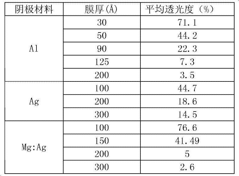
参见图3、图4及上述表1,从上述数据可以看出,随着各种阴极材料薄膜厚度的增加,薄膜透光度都出现急剧下降的趋势,因此透明阴极的厚度不能太厚。另外,虽然Al膜在

当Al薄膜厚度为

锂的电子注入性能大大由于铝,但由于锂金属本身非常活泼,不易进行蒸镀加热操作,因此人们发明了Al:Li合金进行OLED阴极制作,同时为改善Al:Li合金的电子注入及成膜性能,本申请认为Al的质量百分比(即Al-Li合金中的Al元素所占的质量比)范围可取90%~99.95%,Li的质量百分比(即Al-Li合金中的Li元素所占的质量比)范围可取10%~0.05%。The electron injection performance of lithium is much better than that of aluminum, but because lithium metal itself is very active, it is not easy to perform evaporation and heating operations, so people invented Al:Li alloy for OLED cathode production, and at the same time, in order to improve the electron injection and film formation of Al:Li alloy Performance, the application thinks that the mass percentage of Al (that is, the mass ratio of the Al element in the Al-Li alloy) ranges from 90% to 99.95%, and the Li mass percentage (that is, the Li element in the Al-Li alloy occupies Mass ratio) can be in the range of 10% to 0.05%.
上述优选实施方式中的OLED复合透明阴极结构的制备方法如下:The preparation method of the OLED composite transparent cathode structure in the preferred embodiment is as follows:
a.在真空条件下,利用热蒸镀或者电子束蒸镀技术,蒸镀5nm厚度的Al-Li材料作为透明阴极层;a. Under vacuum conditions, use thermal evaporation or electron beam evaporation technology to evaporate Al-Li material with a thickness of 5nm as a transparent cathode layer;
b.在真空条件下,在透明阴极层的上方,利用热蒸镀或者电子束蒸镀技术,蒸镀15nm厚度的Ag材料作为辅助透明阴极层。b. Under vacuum conditions, on the top of the transparent cathode layer, use thermal evaporation or electron beam evaporation technology to evaporate Ag material with a thickness of 15nm as the auxiliary transparent cathode layer.
如此,辅助透明阴极层与透明阴极层结合形成了复合透明阴极结构。In this way, the auxiliary transparent cathode layer is combined with the transparent cathode layer to form a composite transparent cathode structure.
采用上述OLED复合透明阴极结构制备的OLED器件结构如图2所示,经过多次试验测试,该OLED器件的性能与传统技术中采用5nm厚的Al材料作透明阴极层,采用15nm厚的Ag材料作辅助透明阴极层的OLED器件的性能对比如下表2所示:The structure of the OLED device prepared by using the above OLED composite transparent cathode structure is shown in Figure 2. After many experiments and tests, the performance of the OLED device is comparable to that of the traditional technology using 5nm thick Al material as the transparent cathode layer and using 15nm thick Ag material. The performance comparison of the OLED device used as the auxiliary transparent cathode layer is shown in Table 2 below:
表2Table 2

上述表中,“Al/Ag阴极器件”表示采用Al材料制作透明阴极层,采用Ag材料制作辅助透明阴极层的OLED器件;“Al:Li/Ag阴极器件”表示采用Al-Li合金材料制作透明阴极层,采用Ag材料制作辅助透明阴极层的OLED器件。In the above table, "Al/Ag cathode device" means that Al material is used to make the transparent cathode layer, and Ag material is used to make the auxiliary transparent cathode layer of the OLED device; "Al:Li/Ag cathode device" means that Al-Li alloy material is used to make the OLED device The cathode layer is an OLED device with an auxiliary transparent cathode layer made of Ag material.
本发明所要求保护的技术方案包含但不仅限于上述实施方式中的内容,在不脱离本发明的精神实质的情况下,本领域技术人员根据上述实施方式所记载的内容对本发明的方案作出的等同替换均在本发明的保护范围内。The technical solutions claimed in the present invention include but are not limited to the content in the above-mentioned embodiments. Without departing from the spirit of the present invention, those skilled in the art can make equivalents to the solutions of the present invention based on the contents recorded in the above-mentioned embodiments. All replacements are within the protection scope of the present invention.
Claims (8)
Priority Applications (1)
| Application Number | Priority Date | Filing Date | Title |
|---|---|---|---|
| CN201210076436XA CN102569670A (en) | 2012-03-21 | 2012-03-21 | OLED composite transparent cathode structure and preparation method thereof |
Applications Claiming Priority (1)
| Application Number | Priority Date | Filing Date | Title |
|---|---|---|---|
| CN201210076436XA CN102569670A (en) | 2012-03-21 | 2012-03-21 | OLED composite transparent cathode structure and preparation method thereof |
Publications (1)
| Publication Number | Publication Date |
|---|---|
| CN102569670A true CN102569670A (en) | 2012-07-11 |
Family
ID=46414568
Family Applications (1)
| Application Number | Title | Priority Date | Filing Date |
|---|---|---|---|
| CN201210076436XA Pending CN102569670A (en) | 2012-03-21 | 2012-03-21 | OLED composite transparent cathode structure and preparation method thereof |
Country Status (1)
| Country | Link |
|---|---|
| CN (1) | CN102569670A (en) |
Cited By (5)
| Publication number | Priority date | Publication date | Assignee | Title |
|---|---|---|---|---|
| WO2016082393A1 (en) * | 2014-11-28 | 2016-06-02 | 京东方科技集团股份有限公司 | Organic light-emitting diode display substrate and manufacturing method therefor, and display apparatus |
| CN107359278A (en) * | 2017-05-22 | 2017-11-17 | 茆胜 | A kind of method for repairing and mending of OLED minitype displayer cathodic coating fracture |
| CN107768546A (en) * | 2017-11-06 | 2018-03-06 | 华南理工大学 | A kind of organic electroluminescence display panel and preparation method thereof, display device |
| CN111524460A (en) * | 2020-04-26 | 2020-08-11 | 武汉华星光电半导体显示技术有限公司 | Display panel, mask, and method for manufacturing the display panel |
| CN113053978A (en) * | 2021-03-12 | 2021-06-29 | 武汉华星光电半导体显示技术有限公司 | Display panel and display device |
Citations (3)
| Publication number | Priority date | Publication date | Assignee | Title |
|---|---|---|---|---|
| CN1767707A (en) * | 2000-02-03 | 2006-05-03 | 株式会社半导体能源研究所 | display device |
| CN1825662A (en) * | 2006-02-09 | 2006-08-30 | 友达光电股份有限公司 | Organic Electroluminescent Devices |
| CN1996639A (en) * | 2005-02-16 | 2007-07-11 | 三星Sdi株式会社 | Organic light emitting device comprising multilayer cathode |
-
2012
- 2012-03-21 CN CN201210076436XA patent/CN102569670A/en active Pending
Patent Citations (3)
| Publication number | Priority date | Publication date | Assignee | Title |
|---|---|---|---|---|
| CN1767707A (en) * | 2000-02-03 | 2006-05-03 | 株式会社半导体能源研究所 | display device |
| CN1996639A (en) * | 2005-02-16 | 2007-07-11 | 三星Sdi株式会社 | Organic light emitting device comprising multilayer cathode |
| CN1825662A (en) * | 2006-02-09 | 2006-08-30 | 友达光电股份有限公司 | Organic Electroluminescent Devices |
Non-Patent Citations (2)
| Title |
|---|
| 黄春辉、李富友、黄维: "《有机电致发光材料与器件导论》", 30 September 2005, 复旦大学出版社 * |
| 黄涌: "聚合物顶发射发光二极管的研究", 《广州化工》 * |
Cited By (8)
| Publication number | Priority date | Publication date | Assignee | Title |
|---|---|---|---|---|
| WO2016082393A1 (en) * | 2014-11-28 | 2016-06-02 | 京东方科技集团股份有限公司 | Organic light-emitting diode display substrate and manufacturing method therefor, and display apparatus |
| US10205117B2 (en) | 2014-11-28 | 2019-02-12 | Boe Technology Group Co., Ltd. | Organic light-emitting diode display substrate having auxiliary electrodes to mitigate an internal resistance drop, method for manufacturing the same and display device |
| CN107359278A (en) * | 2017-05-22 | 2017-11-17 | 茆胜 | A kind of method for repairing and mending of OLED minitype displayer cathodic coating fracture |
| CN107768546A (en) * | 2017-11-06 | 2018-03-06 | 华南理工大学 | A kind of organic electroluminescence display panel and preparation method thereof, display device |
| CN111524460A (en) * | 2020-04-26 | 2020-08-11 | 武汉华星光电半导体显示技术有限公司 | Display panel, mask, and method for manufacturing the display panel |
| CN111524460B (en) * | 2020-04-26 | 2021-10-01 | 武汉华星光电半导体显示技术有限公司 | Display panel, mask, and method for manufacturing the display panel |
| CN113053978A (en) * | 2021-03-12 | 2021-06-29 | 武汉华星光电半导体显示技术有限公司 | Display panel and display device |
| US11925095B2 (en) | 2021-03-12 | 2024-03-05 | Wuhan China Star Optoelectronics Semiconductor Display Technology Co., Ltd. | Display panel and display device |
Similar Documents
| Publication | Publication Date | Title |
|---|---|---|
| KR101148886B1 (en) | Organic light emitting diode and manufacturing method thereof | |
| US10103349B2 (en) | Electroluminescent device and manufacturing method thereof, display substrate and display device | |
| US11227999B2 (en) | Array substrate having a layer of magnetic material, display panel having the same and manufacturing method the same thereof | |
| CN106784389A (en) | A kind of composite transparent electrode, Organic Light Emitting Diode and preparation method thereof | |
| CN102569670A (en) | OLED composite transparent cathode structure and preparation method thereof | |
| JP2016035888A (en) | Inverse structure top emission type device and manufacturing method thereof | |
| CN105655494B (en) | Substrate of Organic Light Emitting Diode and preparation method thereof, Organic Light Emitting Diode | |
| WO2021031517A1 (en) | Display panel and display device having same | |
| US8907355B2 (en) | Display apparatus having a double sided emission organic light emitting diode comprising a composite anode, and a composite cathode including a non-transparent metal layer | |
| CN102709486B (en) | Application of LiF film, OLED packaging structure and packaging method | |
| TWI253878B (en) | Organic electroluminescent element and display device including the same | |
| CN103000814B (en) | Top emission type organic electro luminescent device, its preparation method and display unit | |
| CN102593373A (en) | A kind of OLED composite transparent cathode structure and preparation method thereof | |
| CN104466025A (en) | Reflecting electrode and preparation method and application thereof | |
| CN101405366B (en) | Fabrication method for organic light emitting device and organic light emitting device fabricated by the same method | |
| CN204271141U (en) | Organic electroluminescence device and the display with this device | |
| CN104979285A (en) | Organic light emitting diode display and manufacturing method thereof | |
| US20160028038A1 (en) | Tandem organic light emitting diode and preparation method thereof | |
| CN104795508A (en) | Flexible OLED device structure and preparation method thereof | |
| CN204088384U (en) | A kind of inversion OLED structure based on flexible base, board | |
| CN107768546B (en) | Organic light-emitting display panel, preparation method thereof and display device | |
| JP2011040173A (en) | Organic electroluminescent device | |
| CN208173629U (en) | Electrode and Organnic electroluminescent device | |
| CN106898707A (en) | A kind of top emission OLED device and preparation method, display panel | |
| CN103165822A (en) | Semi-transparent anode of OLED device and OLED device |
Legal Events
| Date | Code | Title | Description |
|---|---|---|---|
| C06 | Publication | ||
| PB01 | Publication | ||
| C10 | Entry into substantive examination | ||
| SE01 | Entry into force of request for substantive examination | ||
| C12 | Rejection of a patent application after its publication | ||
| RJ01 | Rejection of invention patent application after publication |
Application publication date: 20120711 |