CN102539506A - Method of electrochemically detecting a sample substance - Google Patents
Method of electrochemically detecting a sample substance Download PDFInfo
- Publication number
- CN102539506A CN102539506A CN2011103861117A CN201110386111A CN102539506A CN 102539506 A CN102539506 A CN 102539506A CN 2011103861117 A CN2011103861117 A CN 2011103861117A CN 201110386111 A CN201110386111 A CN 201110386111A CN 102539506 A CN102539506 A CN 102539506A
- Authority
- CN
- China
- Prior art keywords
- working electrode
- analyte
- ion
- modified
- substrate
- Prior art date
- Legal status (The legal status is an assumption and is not a legal conclusion. Google has not performed a legal analysis and makes no representation as to the accuracy of the status listed.)
- Granted
Links
Images


Classifications
-
- G—PHYSICS
- G01—MEASURING; TESTING
- G01N—INVESTIGATING OR ANALYSING MATERIALS BY DETERMINING THEIR CHEMICAL OR PHYSICAL PROPERTIES
- G01N33/00—Investigating or analysing materials by specific methods not covered by groups G01N1/00 - G01N31/00
- G01N33/48—Biological material, e.g. blood, urine; Haemocytometers
- G01N33/50—Chemical analysis of biological material, e.g. blood, urine; Testing involving biospecific ligand binding methods; Immunological testing
- G01N33/53—Immunoassay; Biospecific binding assay; Materials therefor
- G01N33/543—Immunoassay; Biospecific binding assay; Materials therefor with an insoluble carrier for immobilising immunochemicals
- G01N33/54366—Apparatus specially adapted for solid-phase testing
- G01N33/54373—Apparatus specially adapted for solid-phase testing involving physiochemical end-point determination, e.g. wave-guides, FETS, gratings
- G01N33/5438—Electrodes
Landscapes
- Health & Medical Sciences (AREA)
- Immunology (AREA)
- Life Sciences & Earth Sciences (AREA)
- Engineering & Computer Science (AREA)
- Molecular Biology (AREA)
- Biomedical Technology (AREA)
- Chemical & Material Sciences (AREA)
- Hematology (AREA)
- Urology & Nephrology (AREA)
- Biotechnology (AREA)
- Microbiology (AREA)
- Cell Biology (AREA)
- Food Science & Technology (AREA)
- Medicinal Chemistry (AREA)
- Physics & Mathematics (AREA)
- Analytical Chemistry (AREA)
- Biochemistry (AREA)
- General Health & Medical Sciences (AREA)
- General Physics & Mathematics (AREA)
- Pathology (AREA)
- Investigating Or Analysing Materials By The Use Of Chemical Reactions (AREA)
- Measuring Or Testing Involving Enzymes Or Micro-Organisms (AREA)
Abstract
本发明为了提供一种能够比以往更灵敏地检测待测物的电化学检测方法,用固定在工作电极161上的捕捉物10捕捉待测物S。在工作电极161上形成包含标记结合物20和待测物S的复合物,其中该标记结合物20在溶解性载体21上有与待测物S结合的结合物22、以及含有标记物24的修饰标记物23。然后溶解溶解性载体21,将修饰标记物23诱导至工作电极161上。
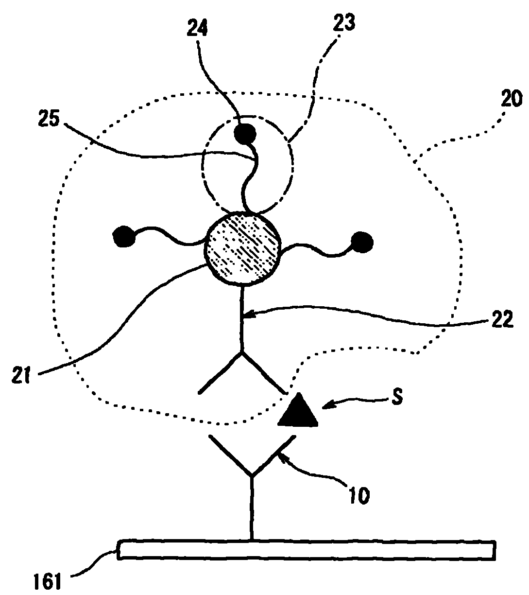
In order to provide an electrochemical detection method capable of detecting the analyte more sensitively than before, the present invention uses the capture object 10 fixed on the working electrode 161 to capture the analyte S. A complex comprising the labeled conjugate 20 and the analyte S is formed on the working electrode 161, wherein the labeled conjugate 20 has a conjugate 22 that binds to the analyte S on a soluble carrier 21, and a complex containing the label 24. Modification markers 23 . Then the soluble carrier 21 is dissolved, and the modified label 23 is induced onto the working electrode 161 .
Description
技术领域:Technical field:
本发明涉及一种待测物的电化学检测方法。更详细地说,本发明涉及一种待测物的电化学检测方法,该方法用于核酸、蛋白质等待测物的检测和定量等,还用于用上述物质进行疾病的临床检查和诊断等。The invention relates to an electrochemical detection method of an analyte. More specifically, the present invention relates to an electrochemical detection method for analytes, which is used for the detection and quantification of nucleic acid and protein analytes, and is also used for clinical examination and diagnosis of diseases with the above substances.
背景技术:Background technique:
在疾病的临床检查和诊断中,一般是用基因检测法和免疫学检测法等检测方法检测生物试样中所含的上述疾病的相关基因和蛋白质等。在这种临床检查和诊断的方法中,已知有待测物的电化学检测方法。具体而言,人们提出的方法中,将下述物用于检测基因和蛋白质等待测物:用光激励具有光化学活性的标记物所产生的电流、对具有电化学活性的标记物施加电压所产生的光或光激励所产生的电流。In the clinical examination and diagnosis of diseases, detection methods such as genetic detection methods and immunological detection methods are generally used to detect the above-mentioned disease-related genes and proteins contained in biological samples. Among such methods of clinical examination and diagnosis, electrochemical detection methods of analytes are known. Specifically, methods have been proposed in which the following are used to detect gene and protein analytes: a current generated by excitation of a photochemically active label with light, a voltage generated by the application of a voltage to an electrochemically active label The current generated by the light or light excitation.
在此,当检测样本中的待测物并进行临床检查和诊断时,往往要求高灵敏度地检测出样本中所含微量待测物。因此,比如美国专利公报(U.S.Patent Publication)第2006/078912号中提出了用载体粒子检测待测物的方法,其中该载体粒子具有有电化学活性的众多ECL和与待测物结合的探针。在此,当进行ECL电化学发光检测时,溶解上述载体,释放ECL,使之分散。以此提高ECL与电解质的接触效率,提高检测灵敏度。如此,人们期望开发出一种能用电化学检测方法更灵敏地检测待测物的电化学检测方法。Here, when detecting the analyte in the sample and performing clinical examination and diagnosis, it is often required to detect a trace amount of the analyte contained in the sample with high sensitivity. Therefore, such as U.S. Patent Publication (U.S.Patent Publication) No. 2006/078912, a method for detecting the analyte with a carrier particle is proposed, wherein the carrier particle has numerous ECLs with electrochemical activity and probes combined with the analyte . Here, when performing ECL electrochemiluminescence detection, the above-mentioned carrier is dissolved to release ECL and disperse it. In this way, the contact efficiency between the ECL and the electrolyte is improved, and the detection sensitivity is improved. In this way, people expect to develop an electrochemical detection method that can more sensitively detect the analyte using the electrochemical detection method.
发明内容:Invention content:
本发明的范围只由后附权利要求书所规定,在任何程度上都不受这一节发明内容的陈述所限。The scope of the present invention is defined only by the appended claims and is not limited in any way by the statements in this summary.
本发明的目的在于提供一种能比以往方法更灵敏地检测出待测物的电化学检测方法。The object of the present invention is to provide an electrochemical detection method that can detect the analyte more sensitively than previous methods.
本发明人经过锐意钻研,发现通过以下三点可以解决上述课题:The inventor has studied hard and found that the above-mentioned problems can be solved by the following three points:
(1)在工作电极上形成含有标记结合物和待测物的复合物,其中,该标记结合物具有与待测物结合的结合物和含标记物的修饰标记物相结合的溶解性载体,(1) forming a complex containing a labeled conjugate and an analyte on the working electrode, wherein the labeled conjugate has a soluble carrier combined with a conjugate bound to the analyte and a modified label containing the label,
(2)溶解此复合物中的标记结合物中所含溶解性载体,以及(2) dissolving the soluble carrier contained in the labeled conjugate in the complex, and
(3)将修饰标记物诱导至工作电极上。(3) Inducing the modified label to the working electrode.
即,本发明人发现,当对待测物进行电化学检测时,通过上述(1)~(3)的操作,无论待测物的大小等,可以高效获取基于与待测物的量相应的标记物的信号,从而得以高灵敏度地对待测物进行电化学检测。That is, the present inventors have found that when the analyte is electrochemically detected, through the above-mentioned operations (1) to (3), regardless of the size of the analyte, etc., it is possible to efficiently obtain a label based on the amount of the analyte. The signal of the analyte can be detected electrochemically with high sensitivity.
本发明正是基于本发明人的这种发现。The present invention is based on this discovery of the present inventors.
因此,本发明提供:Therefore, the present invention provides:
(1)一种用电化学方式检测待测物的方法,包括:让含有待测物的试样接触工作电极,并将其捕捉在工作电极上;让标记结合物接触捕捉有所述待测物的工作电极,在所述工作电极上形成含有所述待测物与所述标记结合物的复合物,其中,所述标记结合物有与待测物结合的结合物和含标记物的修饰标记物相结合的溶解性载体;通过溶解所述工作电极上形成的复合物中所含所述溶解性载体,使所述修饰标记物游离;将所述修饰标记物诱导到工作电极上;对所述修饰标记物中的标记物进行电化学检测。(1) A method for electrochemically detecting an analyte, comprising: allowing a sample containing the analyte to contact a working electrode and capture it on the working electrode; allowing a labeled conjugate to contact and capture the analyte A working electrode of a substance, on which a complex containing the analyte and the labeled conjugate is formed, wherein the labeled conjugate has a conjugate that binds to the analyte and a modification containing the label A soluble carrier combined with a label; by dissolving the soluble carrier contained in the complex formed on the working electrode, the modified label is released; the modified label is induced to the working electrode; The markers in the modified markers are detected electrochemically.
(2)根据(1)所述的方法,其中:修饰标记物还含有诱导用修饰物。(2) The method according to (1), wherein the modified marker further includes an inducible modifier.
(3)根据(2)所述的方法,其中:诱导用修饰物为核酸。(3) The method according to (2), wherein the inducing modifier is a nucleic acid.
(4)根据(3)所述的方法,其中:核酸是DNA或RNA。(4) The method according to (3), wherein the nucleic acid is DNA or RNA.
(5)根据(1)~(4)其中任意一项所述的方法,其特征在于:在诱导步骤中,靠极性的不同将所述修饰标记物诱导到工作电极上。(5) The method according to any one of (1) to (4), characterized in that in the inducing step, the modified label is induced to the working electrode by virtue of a difference in polarity.
(6)根据(5)所述的方法,其中:用含有离液序列高的离子(Chaotropic ion)的液体产生所述不同极性。(6) The method according to (5), wherein: the different polarities are generated with a liquid containing chaotropic ions.
(7)根据(6)所述方法,其中:离液序列高的离子为以下物质构成的群中的至少一种:碘化物离子、溴化物离子、胍离子、硫氰酸离子、三溴乙酸离子、三氯乙酸离子、高氯酸离子、二氯乙酸离子、硝酸离子、氯化物离子、乙酸离子、钡离子、钙离子、锂离子、铯离子、钾离子、镁离子。(7) The method according to (6), wherein: the chaotropic ion is at least one of the group consisting of the following substances: iodide ion, bromide ion, guanidine ion, thiocyanate ion, tribromoacetic acid ions, trichloroacetate ions, perchlorate ions, dichloroacetate ions, nitrate ions, chloride ions, acetate ions, barium ions, calcium ions, lithium ions, cesium ions, potassium ions, magnesium ions.
(8)根据(1)~(4)其中任意一项所述的方法,其中:在游离步骤中,用溶解溶解性载体的溶剂使所述溶解性载体溶解。(8) The method according to any one of (1) to (4), wherein in the dissociating step, the soluble carrier is dissolved with a solvent for dissolving the soluble carrier.
(9)根据(8)所述方法,其中:溶解性载体由溶解于溶剂的金属或其合金构成。(9) The method according to (8), wherein the soluble carrier is made of a metal or an alloy thereof dissolved in a solvent.
(10)根据(9)所述的方法,其中:溶解性载体为金纳米粒子。(10) The method according to (9), wherein the soluble carrier is gold nanoparticles.
(11)根据(8)所述的方法,其中:溶剂含有碘或碘化物。(11) The method according to (8), wherein the solvent contains iodine or iodide.
(12)根据(1)~(4)其中任意一项所述的方法,其中:溶解性载体是因热而熔解的载体;在游离步骤中,通过加热该溶解性载体使所述溶解性载体溶解。(12) The method according to any one of (1) to (4), wherein: the soluble carrier is a carrier that melts due to heat; dissolve.
(13)根据(1)~(4)其中任意一项所述的方法,其中:在检测步骤中,在有电解液存在的情况下对修饰标记物中的标记物进行电化学检测。(13) The method according to any one of (1) to (4), wherein: in the detecting step, electrochemical detection is performed on the markers among the modified markers in the presence of an electrolyte.
(14)根据(1)~(4)其中任意一项所述的方法,其中:游离步骤、诱导步骤和检测步骤均在含有碘化物离子和乙腈的液体中进行。(14) The method according to any one of (1) to (4), wherein: the dissociation step, the induction step and the detection step are all carried out in a liquid containing iodide ions and acetonitrile.
(15)根据(1)~(4)其中任意一项所述的方法,其中:在形成步骤之后进行清洗,以除去游离的标记结合物。(15) The method according to any one of (1) to (4), wherein washing is performed after the forming step to remove free labeled conjugates.
(16)根据(1)~(4)其中任意一项所述的方法,其中:所述工作电极由工作电极主体和固定在此工作电极主体上的、用于捕捉所述待测物的捕捉物构成。(16) The method according to any one of (1) to (4), wherein: the working electrode consists of a working electrode body and a capture device fixed on the working electrode body for capturing the analyte. things constitute.
根据本发明的待测物检测方法,可以提供一种可比以前更灵敏地检测待测物的电化学检测方法。According to the detection method of the analyte of the present invention, an electrochemical detection method capable of detecting the analyte more sensitively than before can be provided.
附图说明:Description of drawings:
图1为在本发明一实施方式涉及的待测物的电化学检测方法中,在工作电极上形成的、包含捕捉物、待测物和标记结合物的复合物的简要说明图;FIG. 1 is a brief illustration of a complex formed on a working electrode, comprising a capture substance, an analyte and a labeled conjugate, in an electrochemical detection method for an analyte according to an embodiment of the present invention;
图2为本发明一实施方式涉及的待测物的电化学检测方法中使用的检测装置的斜视图;2 is a perspective view of a detection device used in an electrochemical detection method for an analyte according to an embodiment of the present invention;
图3为图2所示检测装置的结构框图;Fig. 3 is the structural block diagram of detection device shown in Fig. 2;
图4为本发明一实施方式涉及的待测物的电化学检测方法所用检查芯片的斜视图;Fig. 4 is a perspective view of an inspection chip used in an electrochemical detection method for an analyte according to an embodiment of the present invention;
图5为图4所示检查芯片的A-A线的截面图;Fig. 5 is a cross-sectional view of the A-A line of the inspection chip shown in Fig. 4;
图6A为从下向上看图4所示检查芯片的上基板时的斜视图;FIG. 6A is a perspective view of the upper substrate of the inspection chip shown in FIG. 4 from bottom to top;
图6B为从上向下看图4所示检查芯片的下基板时的斜视图;FIG. 6B is a perspective view of the lower substrate of the inspection chip shown in FIG. 4 viewed from top to bottom;
图7A为光电化学检测法中所用的、包含下基板的工作电极部分的一例的截面说明示意图;7A is a schematic cross-sectional illustration of an example of a working electrode portion including a lower substrate used in a photoelectrochemical detection method;
图7B为光电化学检测法中所用的、包含下基板的工作电极部分的变形例的截面说明示意图;7B is a schematic cross-sectional illustration of a modified example of the working electrode portion including the lower substrate used in the photoelectrochemical detection method;
图8A为光电化学检测法中所用的、包含下基板的工作电极部分的变形例的截面说明示意图;8A is a schematic cross-sectional illustration of a modified example of the working electrode portion including the lower substrate used in the photoelectrochemical detection method;
图8B为光电化学检测法中所用的、包含下基板的工作电极部分的变形例的截面说明示意图;8B is a schematic cross-sectional illustration of a modified example of the working electrode portion including the lower substrate used in the photoelectrochemical detection method;
图9A为氧化还原电流-电化学发光检测法中所用的、包含下基板的工作电极部分的变形例的截面说明示意图;9A is a schematic cross-sectional illustration of a modified example of the working electrode portion including the lower substrate used in the redox current-electrochemiluminescence detection method;
图9B为氧化还原电流-电化学发光检测法中所用的、包含下基板的工作电极部分的变形例的截面说明示意图;9B is a cross-sectional schematic illustration of a modified example of the working electrode portion including the lower substrate used in the redox current-electrochemiluminescence detection method;
图10A为上基板的变形例的平面说明图;10A is a plan explanatory view of a modified example of the upper substrate;
图10B为下基板的变形例的平面说明图;10B is a plan explanatory view of a modified example of the lower substrate;
图11A为上基板的变形例的平面说明图;11A is a plan explanatory view of a modified example of the upper substrate;
图11B为下基板的变形例的平面说明图;11B is a plan explanatory view of a modified example of the lower substrate;
图12A为上基板的变形例的平面说明图;12A is a plan explanatory view of a modified example of the upper substrate;
图12B为下基板的变形例的平面说明图;12B is a plan explanatory view of a modified example of the lower substrate;
图12C为间隔固定部件的斜视说明图;Fig. 12C is an oblique view explanatory diagram of a spacer fixing part;
图13为本发明一实施方式涉及的待测物的电化学检测方法(光电化学检测法)的处理步骤的说明图;13 is an explanatory diagram of the processing steps of the electrochemical detection method (photoelectrochemical detection method) of the analyte according to an embodiment of the present invention;
图14为本发明另一实施方式涉及的待测物的电化学检测方法(氧化还原电流-电化学发光检测法)的处理步骤说明图;14 is an explanatory diagram of the processing steps of the electrochemical detection method (redox current-electrochemiluminescence detection method) of the analyte according to another embodiment of the present invention;
图15A为试验例1中实验号为1的方法的操作步骤的简要说明图;Fig. 15A is a brief explanatory diagram of the operation steps of the method whose experiment number is 1 in the test example 1;
图15B为试验例1中实验号为3的方法的操作步骤的简要说明图;Fig. 15B is a brief explanatory diagram of the operation steps of the method whose experiment number is 3 in the test example 1;
图16为试验例1中实验号为1~4的方法的光电流测定结果图表;Fig. 16 is the photocurrent measurement result chart of the method that experiment number is 1~4 in test example 1;
图17A为试验例1中实验号为1的方法进行光电流测定(检测步骤)时的标记物状态的简要说明图;Fig. 17A is a brief explanatory diagram of the state of the marker when the method whose experiment number is 1 in the test example 1 performs photocurrent measurement (detection step);
图17B为试验例1中实验号为3的方法进行光电流测定(检测步骤)时的标记物状态的简要说明图;Fig. 17B is a brief explanatory diagram of the state of the marker when the method whose experiment number is 3 in the test example 1 performs photocurrent measurement (detection step);
图18为试验例2中实验号为5的方法的操作步骤的简要说明图;Fig. 18 is a brief explanatory diagram of the operation steps of the method whose experiment number is 5 in the test example 2;
图19为试验例2中实验号为5~8的方法的光电流测定结果图表;Fig. 19 is the photocurrent measurement result chart of the method that experiment number is 5~8 in test example 2;
图20A为试验例2中实验号为5的方法进行光电流测定(检测步骤)时的标记物状态的简要说明图;Fig. 20A is a brief explanatory diagram of the state of the marker when the method whose experiment number is 5 in the test example 2 performs photocurrent measurement (detection step);
图20B为试验例2中实验号为7的方法进行光电流测定(检测步骤)时的标记物状态的简要说明图;Fig. 20B is a brief explanatory diagram of the state of the marker when the method whose experiment number is 7 in the test example 2 performs photocurrent measurement (detection step);
图21为试验例3中实验号为9~12的方法的光电流测定结果图表;Fig. 21 is the photocurrent measurement result chart of the method that experiment number is 9~12 in test example 3;
图22为试验例4中用实验号为13和14的试样时的光电流测定结果图表;Fig. 22 is the photocurrent measurement result graph when using experiment numbers as samples of 13 and 14 in test example 4;
图23A为在试验例5中,使用制造例6中获得的第一修饰结合物进行光电流测定(检测步骤)时的标记物状态的简要说明图;23A is a schematic explanatory diagram of the state of the marker when photocurrent measurement (detection step) is performed using the first modified conjugate obtained in Production Example 6 in Test Example 5;
图23B为在试验例5中,使用制造例7中获得的第一修饰结合物进行光电流测定(检测步骤)时的标记物状态的简要说明图;23B is a schematic explanatory diagram of the state of the marker when photocurrent measurement (detection step) is performed using the first modified conjugate obtained in Production Example 7 in Test Example 5;
图23C为在试验例5中,使用制造例8中获得的第一修饰结合物进行光电流测定(检测步骤)时的标记物状态的简要说明图;23C is a schematic explanatory diagram of the state of the marker when photocurrent measurement (detection step) is performed using the first modified conjugate obtained in Production Example 8 in Test Example 5;
图24为在试验例5中,Alexa Fluor750/生物素(数量比)与光电流的关系的调查结果图;Fig. 24 is a graph showing the investigation results of the relationship between Alexa Fluor750/biotin (quantity ratio) and photocurrent in Test Example 5;
图25为在试验例6中待测物的量与光电流的关系的调查结果图表。FIG. 25 is a graph showing the investigation results of the relationship between the amount of a sample to be measured and the photocurrent in Test Example 6. FIG.
具体实施方式:Detailed ways:
下面参照附图,对本发明的具体实施方式进行说明。Specific embodiments of the present invention will be described below with reference to the accompanying drawings.
[用语定义][Term definition]
在说明本发明的实施方式时,先说明一下本说明书中使用的用语的定义。When describing the embodiment of the present invention, definitions of terms used in this specification will first be explained.
在本说明书中,所谓捕捉物(图1中“10”)指用于捕捉待测物S的物质,其固定在工作电极161上。In this specification, the so-called capture substance (“10” in FIG. 1 ) refers to a substance used to capture the analyte S, which is fixed on the working
所谓标记结合物(图1中“20”)指包含溶解性载体(图1中“21”)、修饰标记物(图1中“23”)、以及结合物(图1中“22”)的物质。在图1所示标记结合物20中,修饰标记物23和结合物22固定在溶解性载体21上。The so-called labeled conjugate ("20" in Figure 1) refers to a soluble carrier ("21" in Figure 1), a modified marker ("23" in Figure 1), and a conjugate ("22" in Figure 1). substance. In the
结合物22是用于捕捉待测物S的物质,固定在溶解性载体21上。The conjugate 22 is a substance used to capture the analyte S, and is immobilized on the dissolving
所谓修饰标记物(图1中“23”)指含有标记物(图1中“24”)、能够诱导到工作电极的物质。此用语“修饰标记物”的概念中包含由标记物(图1中“24”)和诱导用修饰物(图1中“25”)构成的物质。当标记物(图1中“24”)能够在其原始状态下诱导到工作电极时,用语“修饰标记物”的概念中仅包含该标记物。The so-called modified label ("23" in Figure 1) refers to a substance that contains a label ("24" in Figure 1) and can be induced to the working electrode. The concept of the term "modified marker" includes a substance consisting of a marker ("24" in FIG. 1) and an inducing modifier ("25" in FIG. 1). The term "modified marker" only includes the marker when it can be induced to the working electrode in its original state ("24" in Fig. 1).
[检测装置的结构][Structure of detection device]
下面根据附图,就本发明的待测物的电化学检测方法中使用的检测装置的一例进行说明。An example of the detection device used in the electrochemical detection method of the analyte of the present invention will be described below with reference to the drawings.
图2为本发明一实施方式涉及的待测物的电化学检测方法中使用的检测装置的斜视图。此检测装置101将具有光化学活性的物质作为标记物,对待测物进行光电化学检测,是一种使用电化学检测方法的检测装置。2 is a perspective view of a detection device used in an electrochemical detection method for an analyte according to an embodiment of the present invention. The
检测装置101包括:用于插入检查芯片120的芯片接收部件111、以及用于显示检测结果的显示器112。The
图3为图2所示检测装置的结构框图。检测装置101有光源113、电流表114、电源115、A/D转换部件116、控制部件117和显示器112。FIG. 3 is a structural block diagram of the detection device shown in FIG. 2 . The
光源113向检查芯片120的工作电极上的标记物照射光线,激励该标记物。光源113只要是能产生激励光的光源即可。这种光源比如有荧光灯、不可见光、杀菌灯、白炽灯、低压水银灯、高压水银灯、氙气灯、水银氙气灯、卤钨灯、金属卤化物灯、LED(白色LED、蓝色LED、绿色LED和红色LED等)、激光(二氧化碳激光、色素激光、半导体激光)、阳光等。在上述光源当中,以荧光灯、白炽灯、氙气灯、卤钨灯、金属卤化物灯、LED、激光或阳光为宜。在上述光源当中,以激光更为理想。也可以根据需要,用分光器和带通滤波器使光源只照射一定波长范围的光。The
电流表114用于测量因被激励的检测物所释放的电子而在检查芯片120内流动的电流。The
电源115用于给检查芯片120上的电极施加一定电位。The
A/D转换部件116用于对电流表114测量的光电流值进行数字化。The A/
控制部件117由CPU、ROM、RAM等构成,用于控制显示器112、光源113、电流表114和电源115的运行。控制部件117根据预先制定的用于反映光电流值与标记物量的关系的检量线,从A/D转换部件116进行了数字化后的光电流值中估算出标记物的量,算出待测物的量。The
显示器112显示控制部件117估算出的待测物的量等信息。The
在本发明中,当按照后述氧化还原电流-电化学发光检测法检测所述标记物时,检测装置也可以没有光源113(无图示)。In the present invention, when the marker is detected by the redox current-electrochemiluminescence detection method described later, the detection device may not have the light source 113 (not shown).
当用电化学发光法检测含有上述标记物的检测物时,使检测装置再具备用于检测标记物产生的光的传感器即可。When the detection substance containing the above-mentioned label is detected by electrochemiluminescence, the detection device may further include a sensor for detecting light generated by the label.
[检查芯片的结构][Check the structure of the chip]
下面说明本发明一实施方式涉及的、用于待测物的电化学检测法的检查芯片120的结构。图4为本发明一实施方式涉及的待测物的电化学检测法所用的检查芯片的斜视图。图5为图4所示检查芯片的AA一线的截面图。The structure of the
检查芯片120包括:上基板130、设在上基板130下方的下基板(电极基板)140、以及夹在上基板130与下基板140之间的间隔固定部件150。在检查芯片120中,上基板130和下基板140在一侧重叠配置。上基板130和下基板140重叠的部分中间夹有间隔固定部件150。The
上基板130如图6A所示,由基板主体130a构成。此基板主体130a上设有用于向内部注入含检测物的试样等的试样注入口130b。此试样注入口130b在基板主体130a上设置于间隔固定部件150的内侧。As shown in FIG. 6A, the
基板主体130a呈矩形。此基板主体130a的形状无特别限定,也可以是多角形、圆盘形等。从便于基板的制作和使用的观点出发,最好是矩形。构成基板主体130a的材料无特别限定,比如可以是玻璃、聚对苯二甲酸乙二酯、聚酰亚胺(PI)树脂等塑料材料、金属等无机材料。在这些材料当中,从确保透光性、足够的耐热性、耐用性和平滑性等、同时降低材料所需成本的观点出发,以玻璃为宜。从确保足够的耐用性的观点来说,基板主体130a的厚度以0.01~1mm为宜,0.1~0.7mm更好,最好是约0.5mm。基板主体130a的大小无特别限定,在检测多种检测物和待测物(多项目)时,根据项目数量而定,通常为20mm×20mmThe substrate
下基板140如图6B所示,包括基板主体140a、工作电极161、对电极166和参比电极169。基板主体140a是与上基板130的基板主体130a大小基本相同的矩形。此基板主体140a的表面有工作电极161、连接此工作电极161的电极导线171、对电极166、连接此对电极166的电极导线172、参比电极169、连接此参比电极169的电极导线173。As shown in FIG. 6B , the
构成基板主体140a的材料只要是具有透光性的材料即可。这种材料无特别限定,比如可以是玻璃、聚对苯二甲酸乙二酯、聚酰亚胺(PI)树脂等塑料材料、金属等无机材料。在这些材料当中,从确保足够的透光性、耐热性、耐用性和平滑性等性能、降低材料所需成本的观点出发,以玻璃为宜。基板主体140a的厚度和大小与上基板130的基板主体130a的构成材料、基板主体130a的厚度和大小相同。The material constituting the substrate
在下基板140中,工作电极161配置于基板主体140a的一侧[图6B的右侧]。电极导线171从工作电极161向基板主体140a的另一侧[图6B的左侧]延伸。对电极166在基板主体140a上配置在工作电极161的外侧的位置[在图6B中为工作电极161的右侧]。电极导线172从对电极166绕过工作电极161向基板主体140a的另一侧[图6B的左侧]延伸。参比电极169隔着工作电极161配置于与对电极166相对的位置。电极导线173从参比电极169向基板主体140a的另一侧[图6B的左侧]延伸。工作电极161的电极导线171、对电极166的电极导线172和参比电极169的电极导线173在基板主体140a的另一侧相互并列配置。电极导线171、172和173从上基板130和下基板140重叠的部分露出,露在外面。In the
工作电极161略呈四角形。The working
图7A为光电化学检测法中所用的、含下基板的工作电极部分的一例的截面示意说明图。7A is a schematic explanatory cross-sectional view of an example of a working electrode portion including a lower substrate used in a photoelectrochemical detection method.
图7A所示工作电极161由基板主体140a和此基板主体140a上的工作电极主体162构成。此工作电极主体162的表面固定有捕捉物10。The working
工作电极主体162由导电层163和在此导电层163的表面的电子收纳层164构成[参照图7A]。The working
导电层163由导电材料构成。上述导电材料如可以是金、银、铜、碳、白金、钯、铬、铝、镍等金属或至少含其中之一的合金;可以是掺杂氧化铟和锡的氧化铟等氧化铟类材料;可以是掺杂氧化锡、锑的氧化锡(ATO)和掺杂氟的氧化锡(FTO)等氧化锡类材料;可以是钛、氧化钛和氮化钛等钛材料;可以是由石墨、玻璃碳、热解石墨(pyrolyticgraphite)、碳糊、碳纤维等构成的碳类材料。The
导电层163的厚度以1~1000nm为宜,最好是10~200nm。The thickness of the
导电材料也可以是在玻璃、塑料等非导电物质构成的非导电性材质表面设置由导电材料构成的导电材料层而构成的复合材质。这种导电材料层形状可以是薄膜状和点状其中任何一种。构成导电材料层的材料例如有掺杂锡的氧化铟(ITO)、掺杂氟的氧化锡(FTO)、掺杂锑的氧化锡(ATO)等。The conductive material may also be a composite material formed by disposing a layer of conductive material made of conductive material on the surface of a non-conductive material made of non-conductive material such as glass or plastic. The shape of the conductive material layer may be any of film shape and dot shape. The material constituting the conductive material layer includes, for example, tin-doped indium oxide (ITO), fluorine-doped tin oxide (FTO), antimony-doped tin oxide (ATO), and the like.
导电层163可以用与构成该导电层163的材料的种类相应的膜成型法制作。膜成型法有蒸镀法、溅射法、压印法、丝网印刷法、镀膜处理法、溶胶-凝胶法、旋压覆盖法(Spin Coat)、浸渍法、气相蒸镀法等。The
电子收纳层164含有能够接受电子的物质(电子收纳物质)。所述电子收纳物质只要能够获取可注入检测物在光激励下产生的电子的能级(energy level)即可。在此,在以半导体为电子收纳物质的情况下,所谓“可注入检测物在光激励下产生的电子的能级”指导带(conduction band)。即,只要所述电子收纳物质的能级比标记物(后述)的最低未占分子轨道(LUMO)的能级还低即可。The
所述电子收纳物质无特别限定,比如有硅、锗等单质半导体;包括钛、锡、锌、铁、钨、锆、铪、锶、铟、铈、钇、镧、钒、铌、钽等氧化物的氧化物半导体;钛酸锶、钛酸钙、钛酸钠、钛酸钒、铌酸钾等钙钛矿型半导体;含镉、锌、铅、银、锑、铋等硫化物的硫化物半导体;含镓、钛等氮化物的半导体;由镉、铅的硒化物构成的半导体(如硒化镉等);含镉的碲化物的半导体;锌、镓、铟、镉等磷化合物构成的半导体;含砷化鎵、铜-铟-硒化物、铜-铟-硫化物等化合物的半导体;碳等化合物半导体或有机物半导体等。上述半导体既可以是无杂质半导体也可以是含杂质半导体。The electron-accommodating substance is not particularly limited, such as silicon, germanium and other simple semiconductors; including titanium, tin, zinc, iron, tungsten, zirconium, hafnium, strontium, indium, cerium, yttrium, lanthanum, vanadium, niobium, tantalum and other oxides oxide semiconductors; perovskite semiconductors such as strontium titanate, calcium titanate, sodium titanate, vanadium titanate, and potassium niobate; sulfides containing sulfides such as cadmium, zinc, lead, silver, antimony, and bismuth Semiconductors; semiconductors containing gallium, titanium and other nitrides; semiconductors composed of cadmium and lead selenides (such as cadmium selenide, etc.); semiconductors containing cadmium tellurides; zinc, gallium, indium, cadmium and other phosphorus compounds Semiconductors; semiconductors containing gallium arsenide, copper-indium-selenide, copper-indium-sulfide and other compounds; compound semiconductors such as carbon or organic semiconductors, etc. The aforementioned semiconductor may be either an impurity-free semiconductor or an impurity-containing semiconductor.
在上述半导体中,以氧化物半导体为宜。在上述氧化物半导体中,无杂质半导体以氧化钛、氧化锌、氧化锡、氧化铌、氧化铟、氧化钨、氧化钽及钛酸锶为宜。在上述氧化物半导体中,含杂质半导体以掺杂锡的氧化铟和掺杂氟的氧化锡为宜。掺杂锡的氧化铟和掺杂氟的氧化锡兼有电子收纳物质和导电材料二者的性质。因此,这些材料均可以单独作为构成工作电极主体的材料使用。Among the above-mentioned semiconductors, oxide semiconductors are preferable. Among the above-mentioned oxide semiconductors, titanium oxide, zinc oxide, tin oxide, niobium oxide, indium oxide, tungsten oxide, tantalum oxide, and strontium titanate are preferable as impurity-free semiconductors. Among the above-mentioned oxide semiconductors, tin-doped indium oxide and fluorine-doped tin oxide are preferable as impurity-containing semiconductors. Tin-doped indium oxide and fluorine-doped tin oxide have properties of both an electron-accepting substance and a conductive material. Therefore, these materials can be used alone as the materials constituting the main body of the working electrode.
电子收纳层164的厚度通常为0.1~100nm,最好为0.1~10nm。The thickness of the
根据构成电子收纳层164的材料种类,可以用与制作导电层163的方法相同的方法制作此电子收纳层164。Depending on the type of material constituting the
当导电层163为上述复合材质时,电子收纳层164位于上述导电材料层上。When the
工作电极主体162的表面(电子收纳层164的表面)上固定有用于捕捉待测物S的捕捉物10[参照图7A]。以此可以使工作电极主体162附近有待测物S。On the surface of the working electrode main body 162 (the surface of the electron storage layer 164 ), a
这种捕捉物10可根据待测物S的种类适当选择。作为上述捕捉物10比如有核酸、蛋白质、缩氨酸、糖链、抗体、具有特异性识别能力的纳米结构体等。Such a
工作电极主体162表面上的捕捉物10的固定量无特别限定。工作电极主体162表面上的捕捉物10的固定量可根据比如用途和目的适当设定。The fixed amount of the
可通过化学吸附到工作电极主体162的结合基等将捕捉物10固定到工作电极主体162的表面。这种结合基如有巯醇基、羟基、磷酸基、羧基、羰基、醛基、磺基、氨基等。也可以通过光固化树脂或物理吸附法将捕捉物10固定到工作电极主体162的表面。The
也可以用硅烷偶联剂等对工作电极主体162进行表面处理。经过这种表面处理,可以适当调整工作电极主体162的表面,使其具有亲水性或疏水性。上述硅烷偶联剂如有氨丙基三乙氧基硅烷(APTES)等阳离子型硅烷偶联剂等。The working electrode
图7B、图8A和图8B为光电化学检测法中所使用的、含下基板的工作电极部分的变形例的截面说明图。7B , 8A, and 8B are cross-sectional explanatory views of modified examples of the working electrode portion including the lower substrate used in the photoelectrochemical detection method.
在本发明中,如图7B所示,导电层163也可以位于基板主体140a表面上的绝缘层165上。此时,基板主体140a的表面依次为绝缘层165、导电层163、电子收纳层164。In the present invention, as shown in FIG. 7B , the
此绝缘层165由绝缘体材料构成。上述绝缘体材料无特别限定,如有玻璃、塑料类和氟化物树脂等合成树脂等。可根据绝缘体材料的种类采取适当的方法制作此绝缘层165。上述方法如有溅射法、蒸镀法、丝网印刷法、压印法、浸涂法、喷涂法等。This insulating
在本发明中,如图8A和图8B所示,当构成电子收纳层164的电子收纳物质兼具导电材料的性质时,工作电极主体162也可以仅由电子收纳层164构成。In the present invention, as shown in FIGS. 8A and 8B , when the electron-accommodating substance constituting the electron-accommodating
图9A为氧化还原电流-电化学发光检测法中所使用的、含下基板的工作电极部分的截面说明图。图9B为氧化还原电流电化学发光检测法中所使用的、含下基板的工作电极部分的变形例的截面说明图。9A is an explanatory cross-sectional view of a working electrode portion including a lower substrate used in a redox current-electrochemiluminescence detection method. 9B is a cross-sectional explanatory view of a modified example of the working electrode portion including the lower substrate used in the redox current electrochemiluminescence detection method.
当检查芯片用于氧化还原电流-电化学发光检测法时,工作电极161只要是由对所用溶液等具有稳定性且具有导电性的材料构成的电极即可[参照图9A和图9B]。这种电极如有由石墨、玻璃碳、热解石墨(pyrolytic graphite)、碳糊、碳纤维等构成的碳电极;由白金、铂黑、金、钯、铑等构成的贵金属电极;由氧化钛、氧化锡、氧化锰、氧化铅等构成的氧化物电极;由电子收纳物质硅、锗、氧化锌、硫化镉、二氧化钛、砷化镓等构成的半导体电极;以及由钛构成的钛电极等。When the test chip is used in the redox current-electrochemiluminescence detection method, the working
对电极166由导电性材料制成的薄膜构成。该导电材料如有金、银、铜、碳、白金、钯、铬、铝、镍等金属或至少含这些金属中的其中之一的合金、ITO、氧化铟等导电性陶磁、ATO、FTO等金属氧化物、钛、氧化钛、氮化钛等钛化合物等。上述薄膜的厚度以1~1000nm为宜最好是10~200nm。The
参比电极169由导电材料制成的薄膜构成。该导电材料如有金、银、铜、碳、白金、钯、铬、铝、镍等金属或至少含这些金属中的其中之一的合金、ITO、氧化铟等导电性陶磁、ATO、FTO等金属氧化物、钛、氧化钛、氮化钛等钛化合物等。上述薄膜的厚度以1~1000nm为宜,最好是10~200nm。在本实施方式中设有参比电极169,但本发明也可以不设置参比电极169。根据对电极166所用的电极种类和膜厚而定,但当测定电压降低的影响微小的微弱电流(如1μA以下)时,对电极166也可以兼参比电极169。而当测定较大的电流时,为控制电压降低的影响,稳定施加在工作电极161上的电压,最好设置参比电极169。The
间隔固定部件150是矩形的环状形状,由绝缘体硅胶构成。此间隔固定部件150包围着工作电极161、对电极166和参比电极169(参照图5和图6)。在上基板130和下基板140之间由与间隔固定部件150的厚度相等的间隔。以此,各电极161、166、169之间形成了用于容纳试样和电解液的空间120a(参照图5)。间隔固定部件150的厚度通常为0.2~300μm。在本发明中,也可以用聚酯膜制成的两面胶带等取代硅胶作为构成间隔固定部件150的材料。The
[检查芯片的变形例][modified example of inspection chip]
在本发明中,工作电极161、对电极166和参比电极169配置在间隔固定部件150的框架内,且各电极与其他电极不接触。因此,工作电极161、对电极166和参比电极169也可以位于不同的基板主体上。即,检查芯片可以具有以下部分:在基板主体131a上设置有试样注入口131b和参比电极169的上基板131[参照图10A]、以及在基板主体141a上设置有工作电极161和对电极166的下基板141[参照图10B]。检查芯片也可以具有以下部分:在基板主体132a上设置有试样注入口132b、对电极166和参比电极169的上基板132[参照图11A]、以及在基板主体142a上设置有工作电极161的下基板142[参照图11B]。In the present invention, the working
在本发明中,对电极166和参比电极169也可以不是位于基板主体上的薄膜状电极。即检查芯片也可以具有以下部分:在基板主体133a上设置有试样注入口133b的上基板133[参照图12A]、在基板主体143a上设置有工作电极161的下基板143[参照图12B]、以及在部件主体151a上设置有对电极166和参比电极169的间隔固定部件151[参照图12C]。此时,对电极166和参比电极169中的至少一个设置在间隔固定部件的部件主体上即可。而且,部件主体上的电极以外的电极设置在上基板和下基板中的某一个上即可。In the present invention, the
[待测物的电化学检测法][Electrochemical detection method of analyte]
本发明的待测物的电化学检测方法的特征在于,其包括:The electrochemical detection method of the analyte of the present invention is characterized in that it comprises:
(A)捕捉步骤,让含有待测物的试样与工作电极接触,将其捕捉到工作电极上;(A) capturing step, allowing the sample containing the analyte to contact the working electrode, and capturing it on the working electrode;
(B)复合物形成步骤,让标记结合物与上述已捕捉到待测物的工作电极接触,在上述工作电极上形成包括上述待测物和上述标记结合物的复合物,其中,上述标记结合物具有与待测物结合的结合物与含有标记物的修饰标记物相结合的溶解性载体;(B) The complex formation step, contacting the labeled conjugate with the above-mentioned working electrode that has captured the analyte, and forming a complex including the above-mentioned analyte and the above-mentioned labeled conjugate on the above-mentioned working electrode, wherein the above-mentioned label binds The substance has a dissolving carrier in which the conjugate combined with the analyte is combined with the modified label containing the label;
(C)游离步骤,溶解在上述工作电极上形成的复合物中所含有的上述溶解性载体,使上述修饰标记物游离;(C) a dissociation step, dissolving the above-mentioned soluble carrier contained in the complex formed on the above-mentioned working electrode, so as to release the above-mentioned modified marker;
(D)诱导步骤,将上述修饰标记物诱导到工作电极上;及(D) an induction step, inducing the above-mentioned modified markers onto the working electrode; and
(E)检测步骤,对上述修饰标记物中的标记物进行电化学检测。(E) A detection step, performing electrochemical detection on the markers in the above-mentioned modified markers.
本发明所述方法的特征之一在于其进行下述(1)~(3)操作。One of the characteristics of the method of the present invention is that it performs the following operations (1) to (3).
(1)在工作电极上形成包括待测物与标记结合物的复合物;(1) Forming a complex comprising the analyte and the labeled conjugate on the working electrode;
(2)溶解此复合物中的标记结合物中所含溶解性载体;及(2) dissolving the soluble carrier contained in the labeled conjugate in the complex; and
(3)将修饰标记物诱导到工作电极上。(3) Inducing the modified label to the working electrode.
通过形成上述复合物可以获得与待测物相应的量的修饰标记物。溶解上述溶解性载体,再将修饰标记物诱导至工作电极上,以此可以在标记物与工作电极之间有效地进行电子交换。因此,采用本发明的方法可以高灵敏度地检测出与待测物相应的量的标记物。The modified label can be obtained in an amount corresponding to the analyte by forming the above-mentioned complex. The above-mentioned soluble carrier is dissolved, and then the modified label is induced to the working electrode, so that electron exchange can be effectively performed between the label and the working electrode. Therefore, the method of the present invention can detect the marker corresponding to the amount of the analyte with high sensitivity.
本发明的方法用具有电化学或光化学活性的物质作为上述标记物。具有电化学活性的物质可以通过基于该物质的氧化还原电流及/或电化学发光检测出来。另一方面,具有光化学活性的物质可以利用该物质因光激励而放出的电子来进行检测。因此,本发明的方法根据标记物的检测技术种类可大致分为光电化学检测法(参照图13)和氧化还原电流-电化学发光检测法(图14)。The method of the present invention uses electrochemically or photochemically active substances as the above-mentioned markers. A substance having electrochemical activity can be detected by redox current and/or electrochemiluminescence based on the substance. On the other hand, photochemically active substances can be detected by electrons emitted by the substance due to light excitation. Therefore, the method of the present invention can be roughly classified into photoelectrochemical detection method (see FIG. 13 ) and redox current-electrochemiluminescence detection method ( FIG. 14 ) according to the detection technique of the marker.
1.光电化学检测法1. Photoelectrochemical detection method
首先就光电化学检测方法进行说明。图13为本发明一实施方式涉及的待测物的电化学检测方法(光电化学检测法)的处理步骤的说明图。光电化学检测法可以使用上述图1所示检测装置和图4所示检查芯片,但不限于此。First, the photoelectrochemical detection method will be described. FIG. 13 is an explanatory diagram of the processing steps of the electrochemical detection method (photoelectrochemical detection method) of the analyte according to one embodiment of the present invention. The photoelectrochemical detection method can use the detection device shown in FIG. 1 and the inspection chip shown in FIG. 4 above, but is not limited thereto.
下面以使用图4所示检查芯片时的情况为例进行说明。In the following, the situation when the chip is inspected as shown in FIG. 4 is used as an example for description.
在光电化学检测法中,首先从检查芯片120的试样注入口130b向该检查芯片内注入含有待测物S的试样。然后,将待测物S捕捉到工作电极161上[上述步骤(A),参照图13(A)]。在步骤(A)中,待测物S被固定在工作电极主体162的表面的捕捉物10捕捉到工作电极161上。此时,上述试样中的待测物S以外的其他物质(杂质F)未被捕捉物10捕捉。In the photoelectrochemical detection method, first, a sample containing the analyte S is injected into the inspection chip from the
在本发明中,只要能将待测物S特异性地捕捉到工作电极161上即可,也可以不用捕捉物10。比如,当以ITO为工作电极时,利用ITO能够与硫醇基结合的特点,能够在不使用捕捉物10的情况下将有硫醇基的待测物S捕捉到工作电极161上。In the present invention, as long as the analyte S can be specifically captured on the working
捕捉物10可根据待测物S的种类适当选择。比如,当待测物S是核酸时,捕捉物10只要是与此核酸杂交的核酸探针或是该核酸的抗体即可。当待测物S是蛋白质或缩氨酸时,捕捉物10只要是此蛋白质或缩氨酸的抗体、蛋白质的配体、缩氨酸的受体蛋白质等即可。The
捕捉物10捕捉待测物S的过程可以在捕捉物10和待测物S结合的条件下进行。捕捉物10和待测物S结合的条件可根据待测物S的种类等适当选择。比如,当待测物S为核酸,且捕捉物10是与上述核酸杂交的核酸探针时,待测物S的捕捉可以在有杂交用缓冲液的条件下进行。当待测物S为核酸,且捕捉物10是上述核酸的抗体时,捕捉待测物S时,可以在有磷酸缓冲生理盐水、羟乙基哌嗪乙磺酸(HEPES)缓冲液、1,4哌嗪二乙磺酸(PIPES)缓冲液、三羟甲基氨基甲烷(Tris)缓冲液等适于进行抗原抗体反应的溶液中进行。The process of capturing the analyte S by the
然后,从试样注入口130b向该检查芯片120内注入标记结合物20a。以此使标记结合物20a与捕捉到工作电极161上的待测物S结合[上述步骤(B),参照图13(B)]。在步骤(B)中,在工作电极161上形成含有捕捉物10、待测物S和标记结合物20a的复合物。Then, the labeled conjugate 20a is injected into the
标记结合物20a由溶解性载体21、含有标记物24a和诱导用修饰物25的修饰标记物23a、以及与待测物S结合的结合物22构成。在标记结合物20a中,修饰标记物23a和结合物22固定在溶解性载体21的表面。The label conjugate 20a is composed of a
标记物24a是在光的照射下被激励而放出电子的物质。标记物24a可以使用金属配合物、有机荧光体、量子点及无机荧光体构成的组群中的至少其中之一。The
标记物的具体例子可以举出:金属酞菁染料、钌配合物、锇配合物、铁配合物、锌配合物、9-苯基氧杂蒽(9-phenylxanthene)类色素、花青色素、金属花青(Metallo Cyanine)色素、氧杂蒽类色素、三苯甲烷(triphenylmethane)类色素、氮蒽(acridine)类色素、恶嗪(Oxazine)类色素、香豆素类色素、部花青(Merocyanine)类色素、若丹菁(rhodacyanine)类色素、聚甲炔(polymethine)类色素、卟啉(porphyrin)类色素、酞菁(phtharocyanine)类色素、若丹明类色素、氧杂蒽(xanthene)类色素、叶绿素类色素、曙红(eosin)类色素、红汞(mercurochrome)类色素、靛青(indigo)类色素、BODIPY(氟硼荧)类色素、CALFluor(卡尔科弗卢尔类色素)、俄勒冈绿(Oregon green)类色素、对甲氨基酚绿(Rhodol)、德克萨斯红、级联蓝(Cascade Blue)、核酸(DNA、RNA等)、硒化镉(cadmium selenide)、碲化镉(Cadmium telluride)、Ln2O3:Re、Ln2O2S:Re、ZnO、CaWO4、MO·xAl2O3:Eu、Zn2SiO4:Mn、LaPO4:Ce、Tb、Cy3、Cy3.5、Cy5、Cy5.5、Cy7、Cy7.5及Cy9(全部为安玛西亚生物科学公司(Amersham Biosciences)生产);AlexaFluor 355、Alexa Fluor 405、AlexaFluor 430、Alexa Fluor 488、AlexaFluor 532、Alexa Fluor 546、AlexaFluor 555、Alexa Fluor 568、AlexaFluor 594、Alexa Fluor 633、AlexaFluor 647、Alexa Fluor 660、AlexaFluor 680、Alexa Fluor 700、AlexaFluor 750和Alexa Fluor 790(全部为分子探针(Molecular Probes)公司生产);DY-610、DY-615、DY-630、DY-631、DY-633、DY-635、DY-636、EVOblue10、EVOblue30、DY-647、DY-650、DY-651、DY-800、DYQ-660和DYQ-661(全部由Dyomics公司生产);Atto425、Atto465、Atto488、Atto495、Atto520、Atto532、Atto550、Atto565、Atto590、Atto594、Atto610、Atto611X、Atto620、Atto633、Atto635、Atto637、Atto647、Atto655、Atto680、Atto700、Atto725和Atto740(全部由Atto-TEC GmbH公司生产);VivoTagS680、VivoTag680和VivoTagS750(全部由VisEnMedical公司生产)。上述Ln表示La、Gd、Lu或Y,Re表示镧类元素,M表示碱土类金属元素,x表示0.5~1.5的数字。关于标记物的其他例子,可以参考美国专利公报第2009/294305号、美国专利第5893999号、特愿2009-23993号公报等。Specific examples of labels include: metal phthalocyanine dyes, ruthenium complexes, osmium complexes, iron complexes, zinc complexes, 9-phenylxanthene (9-phenylxanthene) pigments, cyanine pigments, metal Cyanine (Metallo Cyanine) pigments, xanthene pigments, triphenylmethane (triphenylmethane) pigments, acridine (acridine) pigments, oxazine (Oxazine) pigments, coumarin pigments, merocyanine (Merocyanine) ) pigments, rhodacyanine pigments, polymethine pigments, porphyrin pigments, phthalocyanine pigments, rhodamine pigments, xanthene Pigments, chlorophyll pigments, eosin pigments, mercurochrome pigments, indigo pigments, BODIPY pigments, CALFluor pigments, Oregon green (Oregon green) pigments, rhodol green (Rhodol), Texas red, cascade blue (Cascade Blue), nucleic acid (DNA, RNA, etc.), cadmium selenide (cadmium selenide), telluride Cadmium telluride, Ln2O3: Re, Ln2O2S: Re, ZnO, CaWO4, MO xAl2O3: Eu, Zn2SiO4: Mn, LaPO4: Ce, Tb, Cy3, Cy3.5, Cy5, Cy5.5, Cy7, Cy7. 5 and Cy9 (all produced by Amersham Biosciences); AlexaFluor 355, Alexa Fluor 405, AlexaFluor 430, Alexa Fluor 488, AlexaFluor 532, Alexa Fluor 546, AlexaFluor 555, Alexa Fluor 568, AlexaFluor 594, Alexa Fluor 633, AlexaFluor 647, Alexa Fluor 660, AlexaFluor 680, Alexa Fluor 700, AlexaFluor 750 and Alexa Fluor 790 (all produced by Molecular Probes); DY-610, DY-615, DY-630, DY-631, DY-633, DY-635, DY-636, EVOblue10, EVOblue30, DY-647, DY-65 0, DY-651, DY-800, DYQ-660 and DYQ-661 (all produced by Dyomics); Atto425, Atto465, Atto488, Atto495, Atto520, Atto532, Atto550, Atto565, Atto590, Atto594, Atto610, Atto611X, Atto620 , Atto633, Atto635, Atto637, Atto647, Atto655, Atto680, Atto700, Atto725 and Atto740 (all produced by Atto-TEC GmbH); VivoTagS680, VivoTag680 and VivoTagS750 (all produced by VisEnMedical). The aforementioned Ln represents La, Gd, Lu or Y, Re represents lanthanum elements, M represents alkaline earth metal elements, and x represents a number from 0.5 to 1.5. For other examples of markers, refer to US Patent Publication No. 2009/294305, US Patent No. 5,893,999, Japanese Patent Application Publication No. 2009-23993, and the like.
诱导用修饰物25比如有DNA、RNA等核酸。在本发明中,当标记物24a是能够诱导到工作电极的物质时,也可以不用此诱导用修饰物25。Examples of
在此,当以核酸作为诱导用修饰物时,从将后述修饰标记物23a诱导到工作电极161的观点、从与溶解性载体的结合效率的观点出发,该核酸的长度以1个碱基以上10000个碱基以下为宜,更具体而言,最好在10~40个碱基之间。Here, when a nucleic acid is used as an inducing modifier, the length of the nucleic acid is expressed as 1 base from the viewpoint of inducing the modified
结合物22只要是在待测物S中与捕捉物10不同的位置和地方结合的物质即可。这种结合物22可以根据待测物S的种类适当选择。比如,当待测物S是核酸时,结合物22可以是与此核酸杂交的核酸探针或上述核酸的抗体。当待测物S是蛋白质或缩氨酸时,结合物22只要是此蛋白质或缩氨酸的抗体、蛋白质的配体、缩氨酸的受体蛋白质等即可。The binding
从在后述步骤中易于诱导到工作电极161来看,修饰标记物23a最好由标记物24a和核酸构成。The modified
在步骤(B)中,未与待测物S结合的剩余标记结合物20a在检查芯片120内处于游离状态。因此,步骤(B)之后还要进行去除游离的标记结合物20a的步骤[“清洗步骤”,参照图13(C)]。以此可以提高检测结果的特征。也可以不实施此清洗步骤。在此清洗步骤中使用乙醇、纯净水等。In step (B), the remaining labeled conjugates 20 a not bound to the analyte S are in a free state in the
在光电化学检测法中,接下来使工作电极161上的复合物中所含溶解性载体21溶解,使修饰标记物23a游离[上述步骤(C),参照图13(D)]。In the photoelectrochemical detection method, next, the
溶解性载体21只要是能溶解,使固定在其表面的修饰标记物23a处于游离状态的物质即可。上述溶解性载体21如有:由金、银、钯、铂、铱、铑等金属构成的金属微粒;聚乙烯、聚苯乙烯、聚丙烯腈、尼龙、乙烯-丙烯酸共聚物、苯乙烯-丙烯酸酯、桥联型苯乙烯-丙烯、桥联型聚丙烯酸酯、桥联型聚甲基丙烯酸丁酯、桥联型聚甲基丙烯酸甲酯、硅树脂、苯酚树脂、三聚氰胺-甲醛水溶液、苯代三聚氰胺-甲醛水溶液、苯代三聚氰胺-密胺-甲醛水溶液、聚乳酸、聚酰胺树脂等聚合体构成的聚合体微粒;由具有棕榈酸盐、油酸盐等脂肪酸离子或聚环氧烷、多磷酸、聚天冬氨酸、聚乙二醇等亲水性高分子链部分和聚酰胺酸、聚苯乙烯、聚甲基丙烯酸酯等疏水性高分子链部分的高分子化合物等构成的高分子胶束微粒子;水和磷脂时形成的微小球体粒子-微脂粒;琼脂糖凝胶等多糖类胶体构成的多孔微粒子等。The
在上述溶解性载体21中,从易于操作的角度看,以金纳米粒子(金微粒子)为宜。Among the above-mentioned
另外,溶解性载体21如果仅通过溶解固定修饰标记物的表面部分就能使修饰标记物游离的话,也可以是具有由不同材料构成的数个层的载体。比如可以是如下物质等:在金纳米粒子结合在氧化铁(磁性)纳米粒子周围而形成的金-氧化铁(磁性)纳米粒子中,只溶解金纳米粒子的载体。In addition, the
在不影响构成检查芯片120的基板主体的材料和电极(工作电极、对电极和参比电极)材料质量的条件下,可以采取与溶解性载体21的种类相应方法溶解溶解性载体21。比如需要用溶解溶解性载体21的液体或通过加热溶解性载体21来溶化载体时,可以通过加热溶解性载体21来溶解溶解性载体21。The
当溶解性载体21是上述金属微粒子时,在不影响构成检查芯片120的基板主体的材料和电极(工作电极、对电极和参比电极)材料的质量的条件下,可以通过对金属进行氧化溶解来溶解溶解性载体21。溶解金属微粒子时可以使用含碱类氢氧化物的液体、含碱类氰化物的液体、含亚铁氰化盐的液体、含卤素和卤化物混合物的液体等。含碱类氢氧化物的液体比如有氢氧化钾等溶液。含碱类氰化物的液体比如有含有氰化钠(NaCN)和氢氧化钠的水溶液等。含亚铁氰化盐的液体如有亚铁氰化钾和氰化钾的混合物等。卤元素物质和卤化盐的混合物如有碘和碱碘化物(如碘化铵等)的混合物、溴和碱溴化物(如溴化铵)的混合物等。用于这些溶解液的溶剂如有乙腈等有机溶剂、纯水等。例如,当用金微粒子作为溶解性载体21时,可以使用已知的金剥离液和蚀刻液。When the
当溶解性载体21为上述聚合体微粒子时,在不影响构成检查芯片120的基板主体的材料和电极(工作电极、对电极和参比电极)材料质量的条件下,可以让有机溶剂与该溶解性载体21接触;可以将上述溶解性载体21加热到比构成该溶解性载体21的聚合体溶点更高的温度,溶解溶解性载体21。上述有机溶剂,如有乙腈、醚化合物、氯仿、苯、甲苯、丙酮、二氯甲烷、环戊酮等。When the
当溶解性载体21为上述高分子胶束和微脂粒时,可以用能够击碎胶束的超声波进行处理,或用水稀释等,以此来溶解溶解性载体21。When the
当溶解性载体21为上述多孔微粒子时,可以将上述溶解性载体21加热到高于构成该溶解性载体21的多糖类凝胶的溶点的温度,以此溶解溶解性载体21。When the
当溶解性载体21为金纳米粒子(金微粒)时,可以用含有碘化物离子和乙腈的液体溶解该溶解性载体21。When the
在光电化学检测法中,接下来将修饰标记物23a诱导至工作电极161上[上述步骤(D),参照图13(E)]。如此,在上述步骤(C)中,游离的修饰标记物23a被移送到工作电极161附近。与在上述步骤(C)中仅使修饰标记物23a游离的状态相比,标记物24a与工作电极主体162之间的电子交换更加容易。In the photoelectrochemical detection method, next, the modified
在上述步骤(D)中可以使用将修饰标记物23a诱导至工作电极161附近的溶剂(也称“诱导液”)。可以利用修饰标记物23a、诱导液和工作电极161之间的疏水性相互作用或亲水性相互作用将修饰标记物诱导至工作电极161上,也可以向工作电极161或对电极166施加电压,并利用如此所产生的电泳效果等将修饰标记物诱导至工作电极161上。In the above step (D), a solvent (also referred to as “inducing solution”) for inducing the modified
本诱导步骤比如可以通过以下二种方法进行:For example, this induction step can be carried out by the following two methods:
1)改变诱导液的疏水性·亲水性,以此加强修饰标记物23a与工作电极161之间的疏水性相互作用或亲水性相互作用[即,利用极性的不同将修饰标记物23a诱导至工作电极161](诱导方法1)1) Change the hydrophobicity and hydrophilicity of the inducing solution, so as to strengthen the hydrophobic interaction or hydrophilic interaction between the modified
2)根据修饰标记物23a的电荷,向工作电极161施加正电压或负电压,增加电泳效果[即,利用电泳效果将修饰标记物23a诱导至工作电极161](诱导方法2)。上述诱导方法1和诱导方法2可以分别单独实施,也可以二者结合实施。2) Apply positive or negative voltage to the working
在诱导方法1中,当用核酸作为诱导用修饰物25时,从加强修饰标记物23a与工作电极161之间的疏水性相互作用或亲水性相互作用,便于将检测物诱导至工作电极161附近的观点出发,诱导液最好是含有离液序列高的离子的液体。In
上述离液序列高的离子比如有碘化物离子、溴化物离子、胍离子、硫氰酸盐离子、三溴乙酸离子、三氯乙酸离子、高氯酸离子、二氯乙酸离子、硝酸离子、氯化物离子、乙酸离子、钡离子、钙离子、锂离子、铯离子、钾离子、镁离子等。Ions with high chaotropic sequence include iodide ion, bromide ion, guanidine ion, thiocyanate ion, tribromoacetate ion, trichloroacetate ion, perchlorate ion, dichloroacetate ion, nitrate ion, chloride ion, etc. Compound ions, acetate ions, barium ions, calcium ions, lithium ions, cesium ions, potassium ions, magnesium ions, etc.
当诱导液含有离液序列高的离子时,诱导液中的离液序列高的离子浓度因所使用的离液序列高的离子的种类而不同。上述浓度通常为1.0~8.0mol/L。当离液序列高的离子为胍离子时,诱导液中的离液序列高的离子的浓度通常为4.0~7.5mol/L。当离液序列高的离子为硫氰酸离子时诱导液中的离液序列高的离子的浓度通常为3.0~5.5mol/L。When the induction solution contains a chaotropic ion, the concentration of the chaotropic ion in the induction solution differs depending on the type of chaotropic ion used. The above-mentioned concentration is usually 1.0 to 8.0 mol/L. When the chaotropic ion is a guanidine ion, the concentration of the chaotropic ion in the induction solution is usually 4.0-7.5 mol/L. When the chaotropic ion is thiocyanate ion, the concentration of the chaotropic ion in the induction solution is usually 3.0-5.5 mol/L.
当用核酸(DNA、RNA等)作为标记物24a或诱导用修饰物25时,可以利用惯用的核酸提取及纯化方法的原理,将修饰标记物23a诱导至工作电极161附近。When nucleic acid (DNA, RNA, etc.) is used as the
上述核酸提取及纯化方法可以列举出使用液相的方法和使用核酸结合用载体的方法等。使用液相的方法可以列举出酚/氯仿抽提法(<Biochimica et Biophysica acta>,《生物化学与生物物理学报》,1963年发行,第72卷,pp.619-629)、碱SDS法(<Nucleic AcidResearch>,《核酸研究》,1979年发行,第7卷,pp.1513-1523)、在含盐酸胍的缓冲液中加入乙醇并使核酸沉降的方法(<AnalyticalBiochemistry>,《分析生物化学》,162,1987,463)等。使用核酸结合用载体的方法中,如有用玻璃粒子和碘化钠溶液将核酸吸附到玻璃粒子上并进行分离的方法(<Proc.Natl.Acad.Sci.USA>,《美国国家科学院院刊》,76-2:615-619,1979)、以及用二氧化硅粒子和离液序列高的离子的方法[如参照<J.Clinical.Microbiology>《临床微生物学杂志》,1990年发行,第28卷,pp.495-503,专利第2680462号公报等]等。在使用二氧化硅粒子和离液序列高的离子的方法中,将与核酸结合的二氧化硅粒子和含有能使试样中的核酸游离的离液序列高的离子的溶液与试样混合,使核酸与二氧化硅粒子结合,再清洗除去杂质,然后回收结合在二氧化硅粒子上的核酸。采用上述方法可以便块捷地提取核酸。而且此方法不仅适用于提取DNA,也适合提取更不稳定的RNA,能获得高纯度的核酸是其一大优点。Examples of the above nucleic acid extraction and purification methods include a method using a liquid phase, a method using a nucleic acid-binding carrier, and the like. The method using the liquid phase can include phenol/chloroform extraction method (<Biochimica et Biophysica acta>, "Biochemistry and Biophysics Acta", issued in 1963, volume 72, pp.619-629), alkali SDS method ( <Nucleic AcidResearch>, "Nucleic Acid Research", issued in 1979,
当修饰标记物23a所含有的标记物24a或诱导用修饰物25为核酸时,可以用上述核酸提取和纯化方法中所使用的溶剂为诱导液,将修饰标记物23a诱导至工作电极161附近。此时,最好使用胍离子、碘化物离子、溴化物离子、硫氰酸离子或这些离子的任意组合作为离液序列高的离子,最好使用与核酸结合的电极(如掺杂锡的氧化铟等)作为工作电极161。When the
当修饰标记物23a所含有的标记物24a或诱导用修饰物25为核酸时,根据需要,诱导液也可含有缓冲液。该缓冲液只要是用于使核酸保持稳定的普通缓冲液即可。从使核酸保持稳定的角度出发,上述缓冲液从以在中性附近、即在pH5.0~9.0具有缓冲能为宜。上述缓冲液比如有三羟甲基氨基甲烷-盐酸盐、四硼酸钠-盐酸、磷酸二氢钾-四硼酸钠缓冲液等。缓冲液浓度以1~500mmol/L为宜。When the
另一方面,在诱导方法2中,根据修饰标记物23a的电荷向工作电极161施加正电压或负电压。在此,核酸为负电荷。因此,当修饰标记物23a所含有的标记物24a或诱导用修饰物25为核酸时,向工作电极161施加正电压,以此可以将修饰标记物23a诱导到工作电极161附近。On the other hand, in the
然后,在光电化学检测法中,光照检查芯片120的工作电极161上的修饰标记物23a中的标记物24a,激励标记物24a,测定光电流,以此检测待测物[上述步骤(E),参照图13(F)]。Then, in the photoelectrochemical detection method, the
在步骤(E)中,当上述步骤(D)使用了诱导液时,可以根据需要将诱导液置换为适于电化学检测的电解液。此时,在有电解液存在的情况下对标记物24a进行电化学检测。In step (E), when the above-mentioned step (D) uses an inducer solution, the inducer solution can be replaced with an electrolyte suitable for electrochemical detection as required. At this time, the electrochemical detection of the
另外,当诱导液具有向氧化状态下的标记物24a供应电子的性质、能够对标记物24a进行电化学检测时,在步骤(E)中也可以照旧使用此诱导液。In addition, when the inducing solution has the property of donating electrons to the labeled
上述电解液可以使用含有以下成分的溶液:由能向氧化状态下的标记物24a供应电子的盐构成的电解质、非质子性极性溶剂、质子性极性溶剂或非质子性极性溶剂与质子性极性溶剂的混合物。根据需要,此电解液还可以含有其他成分。The above-mentioned electrolytic solution can use a solution containing the following components: an electrolyte composed of a salt capable of donating electrons to the
电解质如有碘化物、溴化物、金属配合物、硫代硫酸盐、亚硫酸盐及其混合物等。具体而言,上述电解质如有碘化锂、碘化钠、碘化钾、碘化铯、碘化钙等金属碘化物;四烷基碘化铵、吡啶盐碘化物、咪唑碘化物等四级氨化合物的碘盐;溴化锂、溴化钠、溴化钾、溴化铯、溴化钙等金属溴化物;四烷基溴化铵、吡啶盐溴化物等四级氨化合物的溴盐;氰亚铁酸盐、二戊铁离子等金属配合物;硫代硫酸钠、硫代硫酸铵、硫代硫酸钾、硫代硫酸钙等硫代硫酸盐;亚硫酸钠、亚硫酸钾、亚硫酸铵、亚硫酸铁、亚硫酸氢钠、亚硫酸钙等亚硫酸盐;及其混合物等。其中最好是四丙基碘化铵和碘化钙。Electrolytes such as iodide, bromide, metal complexes, thiosulfate, sulfite and mixtures thereof. Specifically, the above-mentioned electrolytes include metal iodides such as lithium iodide, sodium iodide, potassium iodide, cesium iodide, and calcium iodide; quaternary ammonia compounds such as tetraalkylammonium iodide, pyridinium iodide, and imidazole iodide; iodized salt; lithium bromide, sodium bromide, potassium bromide, cesium bromide, calcium bromide and other metal bromides; bromide salts of quaternary ammonia compounds such as tetraalkylammonium bromide and pyridinium bromide; ferric cyanide Salt, metal complexes such as pentapentyl iron ions; thiosulfates such as sodium thiosulfate, ammonium thiosulfate, potassium thiosulfate, calcium thiosulfate; sodium sulfite, potassium sulfite, ammonium sulfite, ferric sulfite, Sodium bisulfite, calcium sulfite and other sulfites; and their mixtures, etc. Of these, tetrapropylammonium iodide and calcium iodide are preferred.
电解液的电解质浓度最好在0.001~15M之间。The electrolyte concentration of the electrolyte solution is preferably between 0.001-15M.
质子极性溶剂可以用水和以水为主并混合有缓冲液成分的极性溶剂等。As the protic polar solvent, water, a polar solvent mainly composed of water mixed with a buffer component, and the like can be used.
非质子极性溶剂,如有乙腈(CH3CN)等腈类;碳酸丙烯酯、碳酸乙烯酯等碳酸盐类、1,3-二甲基咪唑烷酮、3-甲基恶唑烷酮、二烷基咪唑盐等杂环化合物;二甲基甲酰胺、二甲基亚砜、环丁砜等。非质子极性溶剂中以乙腈较为理想。质子极性溶剂和非质子极性溶剂可以单独使用或二者混合使用。质子极性溶剂和非质子极性溶剂的混合物最好是水和乙腈的混合物。Aprotic polar solvents, such as acetonitrile (CH 3 CN) and other nitriles; propylene carbonate, ethylene carbonate and other carbonates, 1,3-dimethylimidazolidinone, 3-methyloxazolidinone, Heterocyclic compounds such as dialkylimidazolium salts; dimethylformamide, dimethyl sulfoxide, sulfolane, etc. Among the aprotic polar solvents, acetonitrile is ideal. The protic polar solvent and the aprotic polar solvent can be used alone or in combination. The mixture of protic polar solvent and aprotic polar solvent is preferably a mixture of water and acetonitrile.
可以使用具有能照射出激励标记物24a的光的波长的光源来照射标记物24a。这种光源可根据标记物24a的种类等适当选择。上述光源如有荧光灯、不可见光、杀菌灯、白炽灯、低压水银灯、高压水银灯、氙气灯、水银氙气灯、卤钨灯、金属卤化物灯、LED(白色LED、蓝色LED、绿色LED和红色LED等)、激光(二氧化碳激光、色素激光、半导体激光)、阳光等。在上述光源当中,以荧光灯、白炽灯、氙气灯、卤钨灯、金属卤化物灯、LED或阳光为宜。在检测步骤中,根据需要,也可以用分光器和带通滤波器,只向标记物24a照射一定波长带的光。The
测定来源于标记物24a的光电流时可以使用电流表、恒电势器、记录仪及带计算机的测定装置等。When measuring the photocurrent derived from the
在此步骤(E)中,可以通过定量光电流来测量待测物的量。In this step (E), the amount of the analyte can be measured by quantitative photocurrent.
2.氧化还原电流-电化学发光检测法2. Redox current-electrochemiluminescence detection method
下面就氧化还原电流-电化学发光检测法进行说明。图14为本发明另一实施方式涉及的待测物的电化学检测方法(氧化还原电流-电化学发光检测法)的处理步骤说明图。The redox current-electrochemiluminescence detection method will be described below. FIG. 14 is an explanatory diagram of the processing steps of the electrochemical detection method (redox current-electrochemiluminescence detection method) of the analyte according to another embodiment of the present invention.
此氧化还原电流-电化学发光检测法也与上述光电化学检测法相同,首先从检查芯片120的试样注入口130b向该检查芯片内注入含有待测物S的试样。然后,将待测物S捕捉到工作电极161上[上述步骤(A),参照图14(A)]。然后,从试样注入口130b向该检查芯片120内注入标记结合物20b。以此使标记结合物20b与捕捉到工作电极161上的待测物S结合[上述步骤(B),参照图14(B)]。This redox current-electrochemiluminescence detection method is also the same as the above-mentioned photoelectrochemical detection method. First, a sample containing the analyte S is injected into the
标记结合物20b由以下构成:含有溶解性载体21、标记物24b和诱导用修饰物25的修饰标记物23b;以及与待测物S结合的结合物22。修饰标记物23b和结合物22固定在溶解性载体21的表面。The label conjugate 20b is composed of: a modified label 23b including a
标记物24b是一种在施加电压时产生氧化还原电流的标记物质或在施加电压时发光的标记物质。The marker 24b is a marker substance that generates redox current when a voltage is applied or a marker substance that emits light when a voltage is applied.
在施加电压时产生氧化还原电流的标记物比如有主要含有能电子性地引起可逆氧化还原反应的金属的金属配合物等。这种金属配合物比如有:三(菲咯啉)(tris(phenanthroline))锌配合物、三(菲咯啉)钌配合物、三(菲咯啉)钴配合物、二(菲咯啉)di(phenanthroline))锌配合物、二(菲咯啉)钌配合物、二(菲咯啉)钴配合物、联吡啶铂配合物、三联吡啶(terpyridine)铂配合物、菲咯啉铂配合物、三(联吡啶)(tris(bipyridyl))锌配合物、三(联吡啶)钌配合物、三(联吡啶)钴配合物、二(联吡啶)锌配合物、二(联吡啶)钌配合物、二(联吡啶)钴配合物等。Labels that generate redox current when a voltage is applied include, for example, metal complexes mainly containing a metal capable of electronically causing a reversible redox reaction. Such metal complexes include: tris (phenanthroline) (tris (phenanthroline)) zinc complex, tris (phenanthroline) ruthenium complex, tris (phenanthroline) cobalt complex, bis (phenanthroline) di(phenanthroline) zinc complex, bis(phenanthroline) ruthenium complex, bis(phenanthroline) cobalt complex, bipyridine platinum complex, terpyridine platinum complex, phenanthroline platinum complex , three (bipyridine) (tris (bipyridyl)) zinc complexes, three (bipyridine) ruthenium complexes, three (bipyridine) cobalt complexes, two (bipyridine) zinc complexes, two (bipyridine) ruthenium complexes Compounds, bis(bipyridyl)cobalt complexes, etc.
氧化还原电流-电化学发光检测法中也可以将能作为诱导用修饰物的核酸作为标记物。当使用核酸作为标记物24b时,可以将来源于腺嘌呤、胸腺嘧啶、鸟嘌呤、胞嘧啶或尿嘧啶的氧化还原电流作为来源于核酸的氧化还原电流。In the redox current-electrochemiluminescence detection method, a nucleic acid that can serve as an inducible modifier can also be used as a label. When a nucleic acid is used as the label 24b, an oxidation-reduction current derived from adenine, thymine, guanine, cytosine, or uracil can be used as the nucleic acid-derived oxidation-reduction current.
因施加电压而发光的标记物质如有发光氨、光泽精、(pyrene)、二苯基蒽(diphenylanthracene)、红荧烯等。Marking substances that emit light when a voltage is applied include luminol, lucigenin, pyrene, diphenylanthracene, rubrene, and the like.
可以使用以下物质加以增强这些标记物的发光:萤火虫荧光素(firefly luciferin)、脱氢萤光素等萤光素诱导体、苯基苯酚、氯酚(chlorophenol)等苯酚类或萘酚类增强物质。The luminescence of these markers can be enhanced with: firefly luciferin, luciferin inducers such as dehydroluciferin, phenolic or naphthol enhancing substances such as phenylphenol and chlorophenol .
诱导用修饰物25和结合物22与光电化学检测法中的诱导用修饰物25和结合物22相同。The
在氧化还原电流-电化学发光检测法中,下一步是除去游离的标记结合20b[“清洗步骤”,参照图14(C)]。溶解工作电极161上形成的复合物中所含的溶解性载体21,使修饰标记物23b游离[上述步骤(C),参照图14(D)]。再将修饰标记物23b诱导至工作电极161上[上述步骤(D),参照图14(E)]。可以以与上述光电化学检测法相同的操作进行这些步骤。In redox current-electrochemiluminescence detection, the next step is to remove free labeled bound 20b ["washing step", see Fig. 14(C)]. The
在氧化还原电流-电化学发光检测法中,接下来对检查芯片120的工作电极161上的修饰标记物23b中的标记物24b施加电压。测定因标记物24b而产生的氧化还原电流或光,以此检测出待测物S[上述步骤(E),参照图14(F)]。在图14(F)中例示了测定光的情况。In the redox current-electrochemiluminescence detection method, next, a voltage is applied to the marker 24 b among the modified markers 23 b on the working
当上述步骤(D)使用了诱导液时,此步骤(E)与光电化学检测法一样,可以根据需要将诱导液置换为适于电化学检测的电解液。此时,在有电解液存在的情况下对标记物24b进行电化学检测。When the above step (D) uses an inducing solution, this step (E) is the same as the photoelectrochemical detection method, and the inducing solution can be replaced with an electrolyte suitable for electrochemical detection as required. At this time, the electrochemical detection of the marker 24b is performed in the presence of an electrolyte solution.
在本步骤(E)中,当测定氧化还原电流时,可以用恒电势器、信号发生器(function generator)、记录仪及带计算机的测定装置等测定氧化还原电流。In this step (E), when the oxidation-reduction current is measured, the oxidation-reduction current can be measured with a potentiostat, a signal generator (function generator), a recorder, a measuring device with a computer, and the like.
此时,可以通过定量氧化还原电流来检测待测物S的量。At this time, the amount of the analyte S can be detected by quantitative redox current.
在本步骤(E)中,当测定因标记物24b而发出的光时,可以使用光子计数器等。此时,可以在光纤的前端设置透明的电极,并用如此获得的光纤电极取代电极,间接进行检测(参照美国专利第5776672号、美国专利第5972692号)。In this step (E), when measuring the light emitted by the marker 24b, a photon counter or the like can be used. In this case, a transparent electrode can be provided at the tip of the optical fiber, and the thus obtained optical fiber electrode can be used instead of the electrode to perform indirect detection (see US Patent No. 5,776,672 and US Patent No. 5,972,692).
[实施例][Example]
下面举实施例详细说明本发明,但本项发明不限定于此。The present invention will be described in detail below with examples, but the present invention is not limited thereto.
(制造例1)(Manufacturing example 1)
运用溅射法,在二氧化硅(SiO2)制成的基板主体上设置工作电极主体,该工作电极主体由掺杂有锡的氧化铟制成的薄膜(厚约200nm)构成。上述薄膜兼导电层和电子收纳层。再在上述工作电极主体上连接工作电极导线,以便与电流表连接。Using a sputtering method, a working electrode body consisting of a thin film (about 200 nm thick) made of tin-doped indium oxide was provided on a substrate body made of silicon dioxide (SiO 2 ). The above-mentioned thin film also serves as a conductive layer and an electron receiving layer. Then connect the working electrode lead to the main body of the working electrode so as to be connected with the ammeter.
然后,用硅烷偶联剂、即3-巯丙基三乙氧基硅烷(MPTES)对获得的工作电极基板的工作电极主体表面进行表面处理。对于捕捉物,用TCEP(三羧甲基磷酸,Tris(2-carboxyethyl)phosphine)对抗鼠IgG抗体的F(ab’)2片段[DAKO公司制]进行还原处理,使其与上述工作电极主体表面的MPTES发生反应,形成二硫键,以此将上述捕捉物固定在上述工作电极主体表面。然后,让阻断剂、即让硫醇化PEG(聚乙二醇)[西格玛奥德里奇公司制]与上述工作电极主体表面剩余的MPTES发生反应。以此获得工作电极基板。Then, the surface of the working electrode main body of the obtained working electrode substrate was surface-treated with a silane coupling agent, ie, 3-mercaptopropyltriethoxysilane (MPTES). For the capture substance, the F(ab')2 fragment of the anti-mouse IgG antibody [DAKO] was reduced with TCEP (Tris(2-carboxyethyl)phosphine) to make it contact with the surface of the main body of the above-mentioned working electrode. The MPTES reacts to form a disulfide bond, thereby immobilizing the capture substance on the surface of the main body of the working electrode. Then, a blocking agent, that is, thiolated PEG (polyethylene glycol) [manufactured by Sigma-Aldrich] was allowed to react with the remaining MPTES on the surface of the main body of the working electrode. In this way, a working electrode substrate was obtained.
(制造例2)(Manufacturing example 2)
运用溅射法,在二氧化硅(SiO2)制成的基板主体上设置由厚约200nm的白金薄膜(导电层)构成的对电极,以此获得对电极基板。在上述对电极处连接对电极导线,以便与电流表连接。至此获得了对电极基板。A counter electrode composed of a platinum thin film (conductive layer) with a thickness of about 200 nm was provided on a substrate main body made of silicon dioxide (SiO 2 ) by sputtering to obtain a counter electrode substrate. Connect the opposite electrode wire at the above-mentioned opposite electrode so as to connect with the ammeter. Thus, the counter electrode substrate was obtained.
(制造例3)(Manufacturing example 3)
修饰标记物使用的是由以下构成的复合物[图15A(d)中的“23a”]:3’端硫醇化的、长度为24个核苷酸的DNA[图15A(d)中的“25”;以下称“诱导用修饰物25”];以及Alexa Fluor 750(Invitrogen公司制)[图15A(d)中的“24a”;以下称“标记物24a”]。The tag was modified using a complex ["23a" in Figure 15A(d)] consisting of 3'-thiolated DNA of 24 nucleotides in length ["23a" in Figure 15A(d) 25"; hereinafter referred to as "
然后,将上述修饰标记物23a和3’端硫醇化的、长度为24个核苷酸的生物素标记DNA[在图15A(d)中为22c;以下称“第一结合物22c”]按10∶1(摩尔比)混合。第一结合物22c由长度为24个核苷酸的DNA[诱导用修饰物25]和生物素[在图15A(d)中为“22c1”]构成。Then, the biotin-labeled DNA [22c in FIG. 15A(d); 10:1 (molar ratio) mixing. The
将560皮摩尔所得混合物与5.6皮摩尔溶解性载体,即金纳米粒子[在图15A(d)中为“21”]混合,使上述修饰标记物23a和第一结合物22c各自的硫醇基结合到溶解性载体21表面。用超过滤法浓缩、纯化所得产物,获得第一修饰结合物20c1。将所得第一修饰结合物20c1加入含有0.1体积%的聚氧乙烯失水山梨糖醇单月桂酸酯(吐温20)的三羟甲基氨基甲烷缓冲液(TBS-T)磷酸缓冲生理盐水中进行混合,使其最终浓度变为1nM,以此得溶液A。560 picomoles of the resulting mixture were mixed with 5.6 picomoles of a soluble carrier, that is, gold nanoparticles ["21" in FIG. to the surface of the
(制造例4)(Manufacturing example 4)
在磷酸缓冲盐水(PBS)中添加抗坏血酸作为电解质,使其浓度达到0.6M,得电解液。Ascorbic acid was added as an electrolyte in phosphate buffered saline (PBS) to make its concentration 0.6M to obtain an electrolyte solution.
(制造例5)(Manufacturing example 5)
混合乙腈和碳酸乙烯酯至体积比为2∶3,得非质子极性溶剂。在上述非质子极性溶剂中溶解四丙基碘化铵(Tetra Proprl AmmoniumIodide)作为电解质盐,直至浓度达到0.6M。在所得溶液中再溶解碘作为电解质,直至浓度达到0.06M,以此得溶解诱导电解液。Mix acetonitrile and ethylene carbonate to a volume ratio of 2:3 to obtain an aprotic polar solvent. Dissolve tetrapropylammonium iodide (Tetra Proprl AmmoniumIodide) in the above-mentioned aprotic polar solvent as an electrolyte salt until the concentration reaches 0.6M. Iodine was redissolved as an electrolyte in the resulting solution until the concentration reached 0.06M, thereby obtaining a dissolution-inducing electrolyte.
上述碘和四丙基碘化铵可以溶解金纳米粒子。由上述碘或四丙基碘化铵生成的碘化物离子能够将第一标记结合物中所含修饰标记物诱导至工作电极上。因此,使用本制造例4获得的溶解诱导电解液,可以在同一液体中溶解标记结合物中的载体,并将修饰标记物诱导至工作电极上,进行电化学检测。The aforementioned iodine and tetrapropylammonium iodide can dissolve gold nanoparticles. Iodide ions generated from the aforementioned iodine or tetrapropylammonium iodide can induce the modified label contained in the first label conjugate to the working electrode. Therefore, using the dissolution-inducing electrolyte obtained in Production Example 4, the carrier in the labeled conjugate can be dissolved in the same liquid, and the modified label can be induced to the working electrode for electrochemical detection.
(试验例1)(Test example 1)
在制造例1获得的电极基板的工作电极主体周围配置硅橡胶(厚度为0.1mm),并将其作为间隔。然后,在此工作电极基板和硅橡胶围成的空间中注入30μL含有鼠IgG(待测物S)的试样[成分:1μg鼠IgG/mL(含有1质量%牛血清白蛋白的三羟甲基氨基甲烷缓冲液(TBS-T))],将上述工作电极基板在25℃静置60分钟。以此让工作电极主体162上的捕捉物10捕捉待测物S[参照图15A(a)]。Silicone rubber (thickness: 0.1 mm) was arranged around the working electrode main body of the electrode substrate obtained in Production Example 1 as a spacer. Then, inject 30 μL of a sample containing mouse IgG (analyte S) into the space surrounded by the working electrode substrate and silicone rubber [ingredients: 1 μg mouse IgG/mL (trimethylol-methyl-sulfate containing 1% by mass bovine serum albumin] aminomethane buffer solution (TBS-T))], and the above-mentioned working electrode substrate was left to stand at 25° C. for 60 minutes. In this way, the
然后,在上述工作电极基板的上述空间加入30μL含有生物素标记抗鼠IgG抗体[图15A(b)中为“22a”;以下也称“第二结合物22a”]的溶液B[成分:4ng生物素标记抗鼠IgG抗体(希格玛公司制)/μg(含有1质量%牛血清白蛋白的三羟甲基氨基甲烷缓冲液(TBS-T))],将上述工作电极基板在25℃静置30分钟[参照图15A(b)]。以此,将第二结合物22a附加到工作电极主体162上的待测物S[参照图15A(c)]。第二结合物22a由与鼠IgG结合的抗鼠IgG抗体22a1和生物素22a2组成。Then, 30 μL of solution B [component: 4 ng] containing biotin-labeled anti-mouse IgG antibody ["22a" in Fig. Biotin-labeled anti-mouse IgG antibody (manufactured by Sigma)/μg (tris buffered solution (TBS-T) containing 1% by mass bovine serum albumin)], and the above-mentioned working electrode substrate was heated at 25°C Let stand for 30 minutes [refer to FIG. 15A(b)]. In this way, the
然后,在上述空间加入30μL含有链酶亲和素[图15A(c)中为“22b”;以下也称“第三结合物22b”]的溶液C[含有400nM链酶亲和素(Vector公司制)的三羟甲基氨基甲烷缓冲液(TBS-T))],将上述工作电极基板在25℃静置30分钟。再在上述空间加入30μL制造例3获得的溶液A,将上述工作电极基板在25℃静置30分钟。以此在工作电极上形成了含有捕捉物10、待测物S和标记结合物20c的复合物[参照图15A(d)]。再用三羟甲基氨基甲烷缓冲液(TBS-T)和纯水清洗工作电极基板(实验号为1)。用不含待测物S的试样取代含有待测物S的试样,除此之外实施与上述同样的操作(实验号为2)。Then, 30 μL of solution C [containing 400 nM streptavidin (Vector Inc. Tris buffer solution (TBS-T))], and the above-mentioned working electrode substrate was left to stand at 25° C. for 30 minutes. Further, 30 μL of the solution A obtained in Production Example 3 was added to the above space, and the above working electrode substrate was left to stand at 25° C. for 30 minutes. Thus, a complex containing the
为进行对照,用30μL含有Alexa Fluor750标记抗鼠IgG抗体201的溶液D[成分:4ng Alexa Fluor750标记抗鼠IgG抗体(Invitrogen公司制)/μL(含有1质量%牛血清白蛋白的三羟甲基氨基甲烷缓冲液(TBST))]取代生物素标记抗鼠IgG抗体、链酶亲和素和制造例3获得的溶液A,除此之外,进行与上述相同的操作(实验号为3)[参照图15B(a)和(b)]。在此,Alexa Fluor750标记抗鼠IgG抗体201由以下构成:与鼠IgG结合的抗鼠IgG抗体202、以及由Alexa Fluor750构成的标记物质203。此外,用不含待测物S的试样取代含有待测物S的试样,除此之外进行与上述相同的操作(实验号为4)。As a control, 30 μL of solution D containing Alexa Fluor750-labeled anti-mouse IgG antibody 201 [ingredients: 4 ng Alexa Fluor750-labeled anti-mouse IgG antibody (manufactured by Invitrogen)/μL (trimethylol [ See Figure 15B (a) and (b)]. Here, the Alexa Fluor750-labeled anti-mouse
用硅橡胶围在上述工作电极基板周围,形成厚0.2mm侧壁。在上述工作电极基板与硅橡胶围成的空间中填充11.5μL制造例4获得的电解液。并用制造例2获得的对电极基板从工作电极基板上方密封填充有上述电解液的空间。以此使工作电极和对电极接触电解液。再将工作电极导线和对电极导线与电流表连接。Surround the working electrode substrate with silicon rubber to form a side wall with a thickness of 0.2 mm. 11.5 μL of the electrolyte solution obtained in Production Example 4 was filled into the space surrounded by the working electrode substrate and the silicone rubber. The counter electrode substrate obtained in Production Example 2 was also used to seal the space filled with the above electrolyte from above the working electrode substrate. In this way, the working electrode and the counter electrode are in contact with the electrolyte. Then connect the working electrode lead and the counter electrode lead to the ammeter.
光源(波长781nm,输出13mW的激光的光源)从工作电极基板一侧向对电极基板照射光。标记物被光照激励,产生电子。上述电子被工作电极传输,在工作电极和对电极之间形成电流。测定此电流。在试验例1中,实验号为1~4的方法中的光电流测定结果见图16。A light source (a laser light source with a wavelength of 781 nm and an output of 13 mW) irradiates light from the working electrode substrate side to the counter electrode substrate. The markers are excited by light, generating electrons. The above-mentioned electrons are transported by the working electrode, forming an electric current between the working electrode and the counter electrode. Measure this current. In Test Example 1, the photocurrent measurement results in the methods of Experiment Nos. 1 to 4 are shown in FIG. 16 .
从图16所示结果得知,当使用制造例4获得的电解液时,实验号为1和3的实验中可以检测出由于待测物S的存在而产生的光电流。然而,与无待测物S时的光电流的差很小[参照图16中的实验号为2和4的实验]。这是因为如图17所示,在实验号为1的方法[参照图17A]和实验号为3的方法[参照图17B]中,工作电极主体162和标记物24a、203之间的距离长,标记物24a、203产生的电子很难送到工作电极主体162。From the results shown in FIG. 16 , it can be known that when the electrolyte solution obtained in Manufacturing Example 4 is used, the photocurrent generated by the presence of the analyte S can be detected in Experiment Nos. 1 and 3. However, the difference from the photocurrent when there is no analyte S is small [refer to experiments with
(试验例2)(Test example 2)
在制造例1获得的工作电极基板的工作电极主体周围配置硅橡胶(厚度为0.1mm),并将其作为间隔。然后,在此工作电极基板和硅橡胶围成的空间中加入30μL含有鼠IgG(待测物S)的试样[成分:1μg鼠IgG/mL(含有1质量%牛血清白蛋白的三羟甲基氨基甲烷缓冲液(TBST))],将上述工作电极基板在25℃静置60分钟。以此让工作电极主体162上的捕捉物10捕捉待测物S[参照图18(A)]。Silicone rubber (thickness: 0.1 mm) was arranged around the working electrode main body of the working electrode substrate obtained in Production Example 1 as a spacer. Then, 30 μL of a sample containing mouse IgG (analyte S) was added to the space surrounded by the working electrode substrate and the silicone rubber [ingredient: 1 μg mouse IgG/mL (trimethylol-methyl-sulfate containing 1% by mass bovine serum albumin] aminomethane buffer solution (TBST))], the above-mentioned working electrode substrate was allowed to stand at 25° C. for 60 minutes. In this way, the
然后,在上述工作电极基板的上述空间加入30μL含有生物素标记抗鼠IgG抗体(第二结合物22a)的溶液B,将上述工作电极基板在25℃静置30分钟。在上述空间加入30μL含有链酶亲和素(第三结合物22b)的溶液C,将上述工作电极基板在25℃静置30分钟。然后,在上述空间加入30μL制造例3获得的溶液A,将上述工作电极基板在25℃静置30分钟。以此在工作电极上形成含有捕捉物10、待测物S和标记结合物20c的复合物[参照图18(B)]。再用三羟甲基氨基甲烷缓冲液(TBS-T)和纯水清洗工作电极基板(实验号为5)。除用不含待测物S的试样取代含有待测物S的试样外,实施与上述同样的操作(实验号为6)。Then, 30 μL of solution B containing biotin-labeled anti-mouse IgG antibody (
为进行对照,用30μL含有Alexa Fluor750标记抗鼠IgG抗体的溶液D取代生物素标记抗鼠IgG抗体、链酶亲和素和制造例3获得的30μL溶液A,除此之外,进行与上述相同的操作(实验号为7)。另外,用不含待测物S的试样取代含有待测物S的试样,除此之外进行与上述相同的操作(实验号为8)。For the control, except that 30 μL of solution D containing Alexa Fluor750-labeled anti-mouse IgG antibody was substituted for biotin-labeled anti-mouse IgG antibody, streptavidin, and 30 μL of solution A obtained in Production Example 3, the same procedure as above was carried out. The operation (experiment number is 7). In addition, the same operation as above was performed except that the sample containing the analyte S was replaced with a sample not containing the analyte S (Experiment No. 8).
用硅橡胶围在上述工作电极基板周围,形成厚0.2mm的侧壁。在上述工作电极基板与硅橡胶围成的空间中填入11.5μL制造例5获得的溶解诱导电解液。并用制造例2获得的对电极基板从工作电极基板上方密封填充有上述溶解诱导电解液的空间。将上述工作电极基板和对电极基板静置5分钟。以此使工作电极和对电极接触溶解诱导电解液。再将工作电极导线和对电极导线与电流表连接。溶解性载体21被制造例5获得的溶解诱导电解液溶解,修饰标记物23a处于游离状态。游离状态的修饰标记物23a被制造例5获得的溶解诱导电解液诱导至工作电极主体162上。Surround the working electrode substrate with silicon rubber to form a side wall with a thickness of 0.2 mm. 11.5 μL of the dissolution-inducing electrolyte solution obtained in Production Example 5 was filled into the space surrounded by the working electrode substrate and the silicone rubber. Also, the counter electrode substrate obtained in Production Example 2 was used to seal the space filled with the above-mentioned dissolution-inducing electrolyte from above the working electrode substrate. The above-mentioned working electrode substrate and counter electrode substrate were left to stand for 5 minutes. In this way, the working electrode and the counter electrode are brought into contact to dissolve the induced electrolyte. Then connect the working electrode lead and the counter electrode lead to the ammeter. The
光源(波长781nm,输出13mW的激光的光源)从工作电极基板一侧向对电极基板照射光,测定光电流。在试验例2中,实验号为5~8的方法中的光电流测定结果见图19。A light source (a laser light source with a wavelength of 781 nm and an output of 13 mW) irradiates light from the working electrode substrate side to the counter electrode substrate to measure the photocurrent. In Test Example 2, the photocurrent measurement results in the methods of Test Nos. 5 to 8 are shown in FIG. 19 .
从图19所示结果可以看出,在使用制造例5获得的电解液时,实验号为5的检测方法检测出的光电流比实验号为7的检测方法检测出的光电流大。这是由于如图20所示,在实验号为7的检测方法[参照图20B]中,由捕捉物、待测物和标记物203组成的复合物的物理体积大,工作电极主体162和标记物203之间的距离长,由标记物203产生的电子难以输送到工作电极主体162,而与此相反,在实验号为5的检测方法[参照图20A]中,由于制造例5获得的溶解诱导电解液会对溶解性载体21进行溶解,同时游离的修饰标记物23a被诱导到工作电极主体162上,因此电子的输送更加容易。It can be seen from the results shown in FIG. 19 that when the electrolyte obtained in Manufacturing Example 5 is used, the photocurrent detected by the detection method with Experiment No. 5 is larger than that detected by the detection method with Experiment No. 7. This is because, as shown in Figure 20, in the detection method with Experiment No. 7 [referring to Figure 20B], the physical volume of the complex composed of the capture substance, the analyte and the
(试验例3)(Test example 3)
在制造例1获得的工作电极基板的工作电极主体周围配置硅橡胶(厚度为0.1mm),并将其作为间隔。在此工作电极基板和硅橡胶围成的空间中加入30μL含有鼠IgG的试样[成分:1μg鼠IgG/mL(含有1质量%牛血清白蛋白的三羟甲基氨基甲烷缓冲液(TBS-T))],将上述工作电极基板在25℃静置30分钟。Silicone rubber (thickness: 0.1 mm) was arranged around the working electrode main body of the working electrode substrate obtained in Production Example 1 as a spacer. Add 30 μL of a sample containing mouse IgG to the space surrounded by the working electrode substrate and the silicone rubber [ingredients: 1 μg of mouse IgG/mL (tris buffered solution containing 1 mass % bovine serum albumin (TBS- T))], the above-mentioned working electrode substrate was left to stand at 25° C. for 30 minutes.
然后,在上述工作电极基板的上述空间中,加入30μL含有生物素标记抗鼠IgG抗体(第二结合物22a)的溶液B,将上述工作电极基板在25℃静置30分钟。在上述空间加入30μL含有链酶亲和素(第三结合物22b)的溶液C,将上述工作电极基板在25℃静置30分钟。然后,在上述空间加入30μL制造例3获得的溶液A,将上述工作电极基板在25℃静置30分钟。然后用三羟甲基氨基甲烷缓冲液(TBS-T)和纯水清洗工作电极基板(实验号为9)。用不含鼠IgG的试样取代含有鼠IgG的试样,除此之外进行与上述同样的操作(实验号为10)。Then, 30 μL of solution B containing biotin-labeled anti-mouse IgG antibody (
为进行对照,用30μL上述溶液D取代生物素标记抗鼠IgG抗体、链酶亲和素和30μL制造例3获得的溶液A,除此之外,进行与上述相同的操作(实验号为11)。另外,用不含鼠IgG的试样取代含有鼠IgG的试样,除此之外进行与上述相同的操作(实验号为12)。For the control, the same operation as above was performed except that 30 μL of the above-mentioned solution D was used instead of the biotin-labeled anti-mouse IgG antibody, streptavidin and 30 μL of the solution A obtained in Production Example 3 (Experiment No. 11) . In addition, the same operation as above was carried out except that a sample containing no mouse IgG was used instead of a sample containing mouse IgG (experiment number 12).
用硅橡胶围在上述工作电极基板周围,形成厚0.2mm的侧壁。在上述工作电极基板与硅橡胶围成的空间中填入11.5μL制造例5获得的溶解诱导电解液,将上述工作电极基板静置5分钟。用乙醇清洗电极基板并进行干燥后,将上述溶解诱导电解液置换为制造例4获得的电解液。从工作电极基板上方用制造例2获得的对电极基板密封填充了上述电解液的空间。以此使工作电极和对电极接触电解液。将工作电极导线和对电极导线与电流表连接。Surround the working electrode substrate with silicon rubber to form a side wall with a thickness of 0.2 mm. 11.5 μL of the dissolution-inducing electrolyte solution obtained in Production Example 5 was filled into the space surrounded by the above-mentioned working electrode substrate and the silicone rubber, and the above-mentioned working electrode substrate was left to stand for 5 minutes. After the electrode substrate was washed with ethanol and dried, the above-mentioned dissolution-inducing electrolyte solution was replaced with the electrolyte solution obtained in Production Example 4. The space filled with the electrolyte solution was sealed with the counter electrode substrate obtained in Production Example 2 from above the working electrode substrate. In this way, the working electrode and the counter electrode are in contact with the electrolyte. Connect the working and counter electrode leads to the ammeter.
光源(波长781nm,输出13mW的激光光源)从工作电极基板一侧向对电极基板照射光,测定光电流。在试验例3中,实验号为9~12的方法中测得的光电流测定结果见图21。A light source (a laser light source with a wavelength of 781 nm and an output of 13 mW) irradiates light from the working electrode substrate side to the counter electrode substrate, and the photocurrent is measured. In Test Example 3, the photocurrent measurement results measured in the methods with test numbers 9 to 12 are shown in FIG. 21 .
从图21所示结果可以看出,实验号为9的检测方法检测出的光电流比实验号为11的检测方法检测出的光电流大。由此结果可以知道,用制造例5获得的溶解诱导电解液来使溶解性载体溶解,并将修饰标记物诱导到工作电极主体上,这样,即使在检测光电流时将制造例5获得的溶解诱导电解液置换为制造例4获得的电解液,也可以灵敏地检测出修饰标记物。由此得知,制造例4获得的电解液在检测待测物时具有足够的电解液的性质。It can be seen from the results shown in FIG. 21 that the photocurrent detected by the detection method with experiment number 9 is larger than that detected by the detection method with experiment number 11. From the results, it can be known that the dissolution-inducing electrolyte obtained in Production Example 5 is used to dissolve the soluble carrier and induce the modified label to the working electrode body, so that even when the photocurrent is detected, the dissolved electrolyte obtained in Production Example 5 The induced electrolyte solution was replaced with the electrolyte solution obtained in Production Example 4, and the modified marker could also be detected sensitively. It can be seen from this that the electrolyte solution obtained in Production Example 4 has sufficient properties of the electrolyte solution when detecting the analyte.
(试验例4)(Test example 4)
在制造例5获得的溶解诱导电解液(实验号为13)或制造例4获得的电解液(实验号为14)中溶解长度为24个核苷酸的Alexa Fluor 750标记DNA,使其浓度达到1nM,得到实验号为13的试样或实验号为14的试样。在此,制造例5获得的溶解诱导电解液具有将Alexa Fluor 750标记DNA诱导至工作电极的作用(诱导作用)。而制造例4获得的电解液没有诱导作用。Alexa Fluor 750 labeled DNA with a length of 24 nucleotides was dissolved in the dissolution-inducing electrolyte (experiment number 13) obtained in manufacture example 5 or in the electrolyte solution (experiment number 14) obtained in manufacture example 4, so that its concentration reached 1 nM, the sample with experiment number 13 or the sample with experiment number 14 was obtained. Here, the dissolution-inducing electrolyte solution obtained in Production Example 5 has the effect of inducing Alexa Fluor 750-labeled DNA to the working electrode (induction effect). However, the electrolytic solution obtained in Production Example 4 had no inductive effect.
将11.5μL实验号为13的试样或11.5μL实验号为14的试样滴到制造例1获得的工作电极基板的工作电极上并静置5分钟。然后用乙醇清洗工作电极。11.5 μL of the sample with experiment number 13 or 11.5 μL of the sample with experiment number 14 was dropped onto the working electrode of the working electrode substrate obtained in Production Example 1 and left to stand for 5 minutes. Then clean the working electrode with ethanol.
用硅橡胶围在上述工作电极基板周围,形成厚0.2mm的侧壁。在上述工作电极基板与硅橡胶围成的空间中填入11.5μL制造例5获得的溶解诱导电解液,用制造例2获得的对电极基板从工作电极基板上方密封填充了上述溶解诱导电解液的空间。光源(波长781nm,输出13mW的激光光源)从工作电极基板一侧向对电极基板照射光,测定光电流。在试验例4中,使用了实验号为13和14的试样的光电流测定结果见图22。Surround the working electrode substrate with silicon rubber to form a side wall with a thickness of 0.2 mm. Fill 11.5 μL of the dissolution-inducing electrolyte obtained in Manufacturing Example 5 into the space surrounded by the above-mentioned working electrode substrate and silicone rubber, and use the counter electrode substrate obtained in Manufacturing Example 2 to seal and fill the above-mentioned dissolution-inducing electrolyte from above the working electrode substrate. space. A light source (a laser light source with a wavelength of 781 nm and an output of 13 mW) irradiates light from the working electrode substrate side to the counter electrode substrate, and the photocurrent is measured. In Test Example 4, the photocurrent measurement results using the samples of Test Nos. 13 and 14 are shown in FIG. 22 .
从图22所示结果可以看出,使用实验号为13的试样,即含具有诱导作用的溶解诱导电解液的试样时,所测得的光电流高于使用实验号为14的试样,即含不具有诱导作用的电解液的试样时的光电流。因此得知,将修饰标记物诱导至工作电极的步骤可以有效地提高信号。It can be seen from the results shown in Figure 22 that when using the sample whose experiment number is 13, that is, the sample containing the dissolution-inducing electrolyte with an inductive effect, the measured photocurrent is higher than that using the sample whose experiment number is 14 , that is, the photocurrent of the sample containing the electrolyte without inductive effect. It was thus known that the step of inducing the modified label to the working electrode was effective in increasing the signal.
(制造例6~8)(Manufacturing examples 6 to 8)
在金纳米粒子(溶解性载体21)上混合第一结合物22c、修饰标记物23a和诱导用修饰物25(3’端硫醇化的、长度为24个核苷酸的DNA),使得第一结合物22c:修饰标记物23a:诱导用修饰物25(摩尔比)为1∶1∶8(制造例6)、1∶3∶6(制造例7)、1∶9∶0(制造例8),分别获得Alexa Fluor 750/生物素(数量比)为1/1的第一修饰结合物[参照图23A中的“20c2”;制造例6]、Alexa Fluor 750/生物素(数量比)为3/1的第一修饰结合物[参照图23B中的“20c3”;制造例7]、或Alexa Fluor 750/生物素(数量比)为9/1的第一修饰结合物[参照图23C中的“20c4”;制造例8]。在含有0.1体积%聚氧乙烯失水山梨糖醇单月桂酸酯(Polyoxyethylene sorbitan monolaurate(吐温20))的三羟甲基氨基甲烷缓冲溶液(TBS-T)中添加所得第一修饰结合物20c2、第一修饰结合物20c3或第一修饰结合物20c4,直至浓度达到1nM,混合后得溶液A2(制造例6)、溶液A3(制造例7)或溶液A4(制造例8)。On the gold nanoparticles (dissolving carrier 21), the first
(试验例5)(Test example 5)
在制造例1获得的工作电极基板的工作电极主体周围配置硅橡胶(厚度为0.1mm),并将其作为间隔。在此工作电极基板和硅橡胶围成的空间中加入30μL试样1[成分:1μg鼠IgG(待测物S)/mL(含有1质量%牛血清白蛋白的三羟甲基基氨基甲烷缓冲液(TBS-T))]或试样2[成分:0μg鼠IgG(待测物S)/mL(含有1质量%牛血清白蛋白的三羟甲基氨基甲烷缓冲液(TBS-T))],将上述工作电极基板在25℃静置60分钟。Silicone rubber (thickness: 0.1 mm) was arranged around the working electrode main body of the working electrode substrate obtained in Production Example 1 as a spacer. Add 30 μL of sample 1 [composition: 1 μg of mouse IgG (analyte S)/mL (trishydroxymethylaminomethane buffer containing 1 mass % bovine serum albumin] into the space surrounded by the working electrode substrate and silicone rubber. solution (TBS-T))] or sample 2 [ingredient: 0 μg mouse IgG (sample S)/mL (tris buffered solution (TBS-T) containing 1% by mass bovine serum albumin] ], the above-mentioned working electrode substrate was left to stand at 25° C. for 60 minutes.
在上述工作电极基板的上述空间中,加入30μL含有生物素标记抗鼠IgG抗体(第二结合物22a)的溶液B,将上述工作电极基板在25℃静置30分钟。在上述空间加入30μL含有链酶亲和素(第三结合物22b)的溶液C,将上述工作电极基板在25℃静置30分钟。然后,在上述空间加入30μL制造例6获得的溶液A2、30μL制造例7获得的溶液A3、或30μL制造例8获得的溶液A4,将上述工作电极基板在25℃静置30分钟。用三羟甲基氨基甲烷缓冲液(TBS-T)和纯水清洗工作电极基板。30 μL of solution B containing biotin-labeled anti-mouse IgG antibody (
用硅橡胶围在上述工作电极基板周围,形成厚0.2mm的侧壁。在上述工作电极基板与硅橡胶围成的空间中填入11.5μL制造例5获得的溶解诱导电解液。用制造例2获得的对电极基板从工作电极基板上方密封填充了上述溶解诱导电解液的空间。将上述工作电极基板和对电极基板静置5分钟。Surround the working electrode substrate with silicon rubber to form a side wall with a thickness of 0.2 mm. 11.5 μL of the dissolution-inducing electrolyte solution obtained in Production Example 5 was filled into the space surrounded by the working electrode substrate and the silicone rubber. The space filled with the above-mentioned dissolution-inducing electrolyte was sealed from above the working electrode substrate using the counter electrode substrate obtained in Production Example 2. The above-mentioned working electrode substrate and counter electrode substrate were left to stand for 5 minutes.
用光源(波长781nm,输出13mW的激光光源)从工作电极基板一侧向对电极基板照射光,测定光电流。在试验例5中,对Alexa Fluor750/生物素(数量比)与光电流之间的关系进行了研究,结果如图24所示。图中,黑矩形表示使用试样1时的光电流,黑圆形表示使用试样2时的光电流。A light source (laser light source with a wavelength of 781 nm and an output of 13 mW) was used to irradiate light from the working electrode substrate side to the counter electrode substrate, and the photocurrent was measured. In Test Example 5, the relationship between Alexa Fluor750/biotin (quantity ratio) and photocurrent was investigated, and the results are shown in FIG. 24 . In the figure, the black rectangles represent the photocurrents when the
从图24所示结果可以看出,标记物Alexa Fluor 750的数量越多,检测出的光电流也越大。由此结果得知,采用本方法可以检测出与标记物的量相应大小的光电流。It can be seen from the results shown in Figure 24 that the greater the amount of the marker Alexa Fluor 750, the greater the detected photocurrent. From the results, it can be seen that the photocurrent corresponding to the amount of the marker can be detected by this method.
(试验例6)(Test example 6)
在制造例1获得的工作电极基板的工作电极主体周围配置硅橡胶(厚度为0.1mm),并将其作为间隔。在此工作电极基板和硅橡胶围成的空间中加入30μL试样3[成分:3ng鼠IgG(待测物S)/mL(含有1质量%牛血清白蛋白的三羟甲基氨基甲烷缓冲液(TBS-T))]、试样4[成分:30ng鼠IgG(待测物S)/mL(含有1质量%牛血清白蛋白的三羟甲基氨基甲烷缓冲液(TBS-T))]、或试样5[300ng鼠IgG(待测物S)/mL磷酸缓冲液],将上述工作电极基板在25℃静置60分钟。Silicone rubber (thickness: 0.1 mm) was arranged around the working electrode main body of the working electrode substrate obtained in Production Example 1 as a spacer. Add 30 μL of sample 3 [composition: 3 ng mouse IgG (analyte S)/mL (tris hydroxymethyl aminomethane buffer solution containing 1 mass % bovine serum albumin] to the space surrounded by the working electrode substrate and silicone rubber (TBS-T))], sample 4 [ingredient: 30 ng mouse IgG (analyte S)/mL (tris buffered solution (TBS-T) containing 1% by mass bovine serum albumin]] , or sample 5 [300ng mouse IgG (analyte S)/mL phosphate buffer], the above-mentioned working electrode substrate was left at 25° C. for 60 minutes.
在上述工作电极基板的上述空间中,加入30μL含有生物素标记抗鼠IgG抗体(第二结合物22a)的溶液B,将上述工作电极基板在25℃静置30分钟。在上述空间加入30μL含有链酶亲和素(第三结合物22b)的溶液C,将上述工作电极基板在25℃静置30分钟。然后,在上述空间加入30μL制造例5获得的溶液A,将上述工作电极基板在25℃静置30分钟。用三羟甲基氨基甲烷缓冲液(TBS-T)和纯水清洗工作电极基板。30 μL of solution B containing biotin-labeled anti-mouse IgG antibody (
用硅橡胶围在上述工作电极基板周围,形成厚0.2mm的侧壁。在上述工作电极基板与硅橡胶围成的空间中填入11.5μL制造例5获得的溶解诱导电解液。用制造例2获得的对电极基板从工作电极基板上方密封填充了上述溶解诱导电解液的空间。将上述工作电极基板和对电极基板静置5分钟。Surround the working electrode substrate with silicon rubber to form a side wall with a thickness of 0.2 mm. 11.5 μL of the dissolution-inducing electrolyte solution obtained in Production Example 5 was filled into the space surrounded by the working electrode substrate and the silicone rubber. The space filled with the above-mentioned dissolution-inducing electrolyte was sealed from above the working electrode substrate using the counter electrode substrate obtained in Production Example 2. The above-mentioned working electrode substrate and counter electrode substrate were left to stand for 5 minutes.
用光源(波长781nm,输出13mW的激光光源)从工作电极基极一侧向对电极基板照射光,测定光电流。在试验例6中,对待测物的数量与光电流的关系进行了研究,结果如图25所示。A light source (laser light source with a wavelength of 781 nm and an output of 13 mW) was used to irradiate light from the base side of the working electrode to the counter electrode substrate, and the photocurrent was measured. In Test Example 6, the relationship between the number of test objects and the photocurrent was studied, and the results are shown in FIG. 25 .
从图25所示结果可以看出,随着待测物数量的增加,检测出的光电流也增强。由此结果可以知道,采用本方法可以定量待测物。It can be seen from the results shown in Figure 25 that with the increase in the number of analytes, the detected photocurrent is also enhanced. From the results, it can be known that the method can be used to quantify the analyte.
Claims (16)
Applications Claiming Priority (2)
| Application Number | Priority Date | Filing Date | Title |
|---|---|---|---|
| JP2010-266819 | 2010-11-30 | ||
| JP2010266819A JP5455878B2 (en) | 2010-11-30 | 2010-11-30 | Electrochemical detection method for test substances |
Publications (2)
| Publication Number | Publication Date |
|---|---|
| CN102539506A true CN102539506A (en) | 2012-07-04 |
| CN102539506B CN102539506B (en) | 2014-11-05 |
Family
ID=45350656
Family Applications (1)
| Application Number | Title | Priority Date | Filing Date |
|---|---|---|---|
| CN201110386111.7A Expired - Fee Related CN102539506B (en) | 2010-11-30 | 2011-11-29 | Method of electrochemically detecting a sample substance |
Country Status (4)
| Country | Link |
|---|---|
| US (1) | US8920626B2 (en) |
| EP (1) | EP2458383B1 (en) |
| JP (1) | JP5455878B2 (en) |
| CN (1) | CN102539506B (en) |
Cited By (3)
| Publication number | Priority date | Publication date | Assignee | Title |
|---|---|---|---|---|
| CN109900670A (en) * | 2019-04-02 | 2019-06-18 | 济南大学 | A bifunctional probe for recognizing iron and fluoride ions and its preparation and application |
| CN110192140A (en) * | 2016-11-16 | 2019-08-30 | 华盛顿大学 | System and method for recycling fluorescence imaging |
| CN116500108A (en) * | 2023-05-25 | 2023-07-28 | 江苏大学 | Preparation method and application of an electrochemiluminescent molecularly imprinted sensor based on AuNCs |
Families Citing this family (12)
| Publication number | Priority date | Publication date | Assignee | Title |
|---|---|---|---|---|
| JP5806892B2 (en) * | 2010-09-30 | 2015-11-10 | シスメックス株式会社 | Electrochemical detection method of detection substance and electrochemical detection method of test substance |
| JP5455878B2 (en) | 2010-11-30 | 2014-03-26 | シスメックス株式会社 | Electrochemical detection method for test substances |
| EP2515112B1 (en) * | 2011-04-22 | 2015-08-12 | Sysmex Corporation | Method for electrochemically detecting analyte |
| WO2019005473A1 (en) * | 2017-06-28 | 2019-01-03 | Accure Health Inc. | Integrated opto nano electronic (ione) sensing |
| CN111693691B (en) * | 2019-03-14 | 2023-09-05 | 天津华科泰生物技术有限公司 | Polymer label based on porphyrin structure |
| US20220283185A1 (en) * | 2019-08-27 | 2022-09-08 | University Of Southern California | Assays for detecting and quantifying a biomarker of pericyte injury |
| EP3960291A1 (en) * | 2020-08-28 | 2022-03-02 | ETH Zurich | In-situ controlled dissolution of metals using electrochemistry |
| DE102021116153A1 (en) * | 2021-06-22 | 2022-12-22 | Prominent Gmbh | Process for the optical activation of the sensor surface, especially for zero chlorine sensors |
| CN114184658B (en) * | 2021-12-13 | 2024-04-02 | 安徽大学 | A method for distinguishing potassium chlorate from potassium bromate |
| CN114184657B (en) * | 2021-12-13 | 2024-04-02 | 安徽大学 | Method for distinguishing potassium chlorate and potassium iodate |
| CN115873056B (en) * | 2022-08-04 | 2025-05-16 | 百力格生物科技(上海)股份有限公司 | Method for synthesizing RNA nucleic acid using mixed deprotecting agents |
| CN116297767B (en) * | 2023-04-04 | 2026-01-02 | 济南大学 | Fabrication and Application of an ECL Sensor Based on Bimetallic Oxide Dual Signal Amplification Using Luminol Emitter |
Citations (2)
| Publication number | Priority date | Publication date | Assignee | Title |
|---|---|---|---|---|
| GB2462062A (en) * | 2008-07-14 | 2010-01-27 | Sec Dep For Innovation Univers | Electrochemical assay |
| CN101726528A (en) * | 2008-10-31 | 2010-06-09 | 希森美康株式会社 | Test chip, detection apparatus, and method for detecting analyte |
Family Cites Families (17)
| Publication number | Priority date | Publication date | Assignee | Title |
|---|---|---|---|---|
| CA1220818A (en) | 1983-05-05 | 1987-04-21 | Hugh A.O. Hill | Assay techniques utilising specific binding agents |
| NL8900725A (en) | 1989-03-23 | 1990-10-16 | Az Univ Amsterdam | METHOD AND COMBINATION OF AGENTS FOR INSULATING NUCLEIC ACID. |
| US5776672A (en) | 1990-09-28 | 1998-07-07 | Kabushiki Kaisha Toshiba | Gene detection method |
| JP3410777B2 (en) | 1993-09-13 | 2003-05-26 | 株式会社東芝 | Ultrafine inorganic phosphor-labeled specific binding substance and detection method using the same |
| US6319670B1 (en) | 1995-05-09 | 2001-11-20 | Meso Scale Technology Llp | Methods and apparatus for improved luminescence assays using microparticles |
| US6753143B2 (en) | 2000-05-01 | 2004-06-22 | Clinical Micro Sensors, Inc. | Target analyte detection using asymmetrical self-assembled monolayers |
| FR2810739B1 (en) * | 2000-06-26 | 2007-01-26 | Centre Nat Rech Scient | ELECTROCHEMICAL IMMUNODOSIS USING COLLOIDAL METAL MARKERS |
| US6703210B2 (en) | 2000-11-02 | 2004-03-09 | Satake Corporation | Method and device for determining concentration of dioxins |
| FR2863053B1 (en) * | 2003-11-28 | 2007-04-06 | Univ Claude Bernard Lyon | NEW HYBRID PROBES WITH EXCELLENT LUMINESCENCE |
| CN101057145B (en) * | 2004-06-23 | 2014-10-22 | 得克萨斯系统大学评议会 | Methods and compositions for the detection of biological molecules using a two particle complex |
| EP1947452B1 (en) | 2005-09-29 | 2014-05-14 | Toto Ltd. | Method for specifically detecting a test substance using photocurrent |
| US20080292545A1 (en) * | 2007-04-04 | 2008-11-27 | Yuehe Lin | Functionalized Encoded Apoferritin Nanoparticles and Processes for Making and Using Same |
| JP5463013B2 (en) | 2007-06-19 | 2014-04-09 | 国立大学法人 岡山大学 | Cartilage marker |
| JP2009222636A (en) * | 2008-03-18 | 2009-10-01 | Panasonic Corp | Measuring method of biological material |
| JP2010107502A (en) * | 2008-09-30 | 2010-05-13 | Sekisui Chem Co Ltd | Quantitative analyzing method and detecting cartridge |
| JP5502413B2 (en) * | 2008-10-31 | 2014-05-28 | シスメックス株式会社 | Test chip, test substance detection device, and test substance specific detection method |
| JP5455878B2 (en) | 2010-11-30 | 2014-03-26 | シスメックス株式会社 | Electrochemical detection method for test substances |
-
2010
- 2010-11-30 JP JP2010266819A patent/JP5455878B2/en not_active Expired - Fee Related
-
2011
- 2011-11-29 US US13/306,710 patent/US8920626B2/en not_active Expired - Fee Related
- 2011-11-29 EP EP20110191086 patent/EP2458383B1/en not_active Not-in-force
- 2011-11-29 CN CN201110386111.7A patent/CN102539506B/en not_active Expired - Fee Related
Patent Citations (2)
| Publication number | Priority date | Publication date | Assignee | Title |
|---|---|---|---|---|
| GB2462062A (en) * | 2008-07-14 | 2010-01-27 | Sec Dep For Innovation Univers | Electrochemical assay |
| CN101726528A (en) * | 2008-10-31 | 2010-06-09 | 希森美康株式会社 | Test chip, detection apparatus, and method for detecting analyte |
Non-Patent Citations (1)
| Title |
|---|
| XUN MAO 等: "《Copper-enhanced gold nanoparticle tags for electrochemical stripping detection of human IgG》", 《TALANTA》 * |
Cited By (6)
| Publication number | Priority date | Publication date | Assignee | Title |
|---|---|---|---|---|
| CN110192140A (en) * | 2016-11-16 | 2019-08-30 | 华盛顿大学 | System and method for recycling fluorescence imaging |
| US11668713B2 (en) | 2016-11-16 | 2023-06-06 | University Of Washington | Systems and methods for cyclic fluorescence imaging |
| CN109900670A (en) * | 2019-04-02 | 2019-06-18 | 济南大学 | A bifunctional probe for recognizing iron and fluoride ions and its preparation and application |
| CN109900670B (en) * | 2019-04-02 | 2021-07-06 | 济南大学 | A bifunctional probe for recognizing iron and fluoride ions and its preparation and application |
| CN116500108A (en) * | 2023-05-25 | 2023-07-28 | 江苏大学 | Preparation method and application of an electrochemiluminescent molecularly imprinted sensor based on AuNCs |
| CN116500108B (en) * | 2023-05-25 | 2025-10-03 | 江苏大学 | Preparation method and application of AuNCs-based electrochemiluminescent molecular imprinting sensor |
Also Published As
| Publication number | Publication date |
|---|---|
| JP2012117888A (en) | 2012-06-21 |
| JP5455878B2 (en) | 2014-03-26 |
| EP2458383A1 (en) | 2012-05-30 |
| CN102539506B (en) | 2014-11-05 |
| US8920626B2 (en) | 2014-12-30 |
| EP2458383B1 (en) | 2014-04-23 |
| US20120132543A1 (en) | 2012-05-31 |
Similar Documents
| Publication | Publication Date | Title |
|---|---|---|
| CN102539506B (en) | Method of electrochemically detecting a sample substance | |
| Zeng et al. | Using graphene-based plasmonic nanocomposites to quench energy from quantum dots for signal-on photoelectrochemical aptasensing | |
| Forster et al. | Electrogenerated chemiluminescence | |
| Valenti et al. | Transparent carbon nanotube network for efficient electrochemiluminescence devices | |
| EP2515112B1 (en) | Method for electrochemically detecting analyte | |
| JP5795184B2 (en) | Electrochemical detection method for test substances | |
| Ghosh et al. | Rapid detection of tumor necrosis factor-alpha using quantum dot-based optical aptasensor | |
| JP5856780B2 (en) | Photoelectrochemical detection method of detection substance and photoelectrochemical detection method of test substance | |
| Yang et al. | Plasmonic TiO2@ Au NPs//CdS QDs photocurrent-direction switching system for ultrasensitive and selective photoelectrochemical biosensing with cathodic background signal | |
| Sun et al. | Sensitive electrogenerated chemiluminescence biosensing method for the determination of DNA hydroxymethylation based on Ru (bpy) 32+-doped silica nanoparticles labeling and MoS2-poly (acrylic acid) nanosheets modified electrode | |
| EP3249396A1 (en) | Metal ion detection method, analyte detection method, electrode substrate, and detection kit | |
| Dong et al. | Low-triggering-potential electrochemiluminescence from surface-confined CuInS2@ ZnS nanocrystals and their biosensing applications | |
| Liao et al. | Linear Ru (bpy) 32+–polymer as a universal probe for sensitive detection of biomarkers with controllable electrochemiluminescence signal-amplifying ratio | |
| Shu et al. | Ultrasensitive label-free electrochemiluminescence immunosensor based on N-(4-aminobutyl)-N-ethylisoluminol-functionalized graphene composite | |
| CN102539741B (en) | Detection device for detecting a test substance, electrode substrate, working electrode, inspection tip, method of detecting a test substance | |
| US20100108539A1 (en) | Method for detecting analyte, detection apparatus, and test chip | |
| Li et al. | A sensitive electrochemical aptasensor based on water soluble CdSe quantum dots (QDs) for thrombin determination | |
| JP2012233878A (en) | Electrochemical detection method for a test substance | |
| US20240210409A1 (en) | Method for detecting substance to be detected within sample | |
| Hua et al. | Quantum dots as immobilized substrate for electrochemical detection of cocaine based on conformational switching of aptamer | |
| JP5931788B2 (en) | Electrochemical detection method for test substances | |
| CN102565381A (en) | Immunoassay method by using conductive microparticle-mediated electrochemical luminescence signals | |
| JP5806892B2 (en) | Electrochemical detection method of detection substance and electrochemical detection method of test substance | |
| Hong et al. | A regenerable electrochemiluminescence aptasensor incorporating poly (ethylenimine) and thiosemicarbazide as dual co-reactants for signal amplification | |
| JP5480105B2 (en) | Electrode substrate, working electrode and inspection chip |
Legal Events
| Date | Code | Title | Description |
|---|---|---|---|
| C06 | Publication | ||
| PB01 | Publication | ||
| C10 | Entry into substantive examination | ||
| SE01 | Entry into force of request for substantive examination | ||
| C14 | Grant of patent or utility model | ||
| GR01 | Patent grant | ||
| CF01 | Termination of patent right due to non-payment of annual fee | ||
| CF01 | Termination of patent right due to non-payment of annual fee |
Granted publication date: 20141105 |