CN102459727A - Method for producing solid carbon by reducing carbon oxides - Google Patents
Method for producing solid carbon by reducing carbon oxides Download PDFInfo
- Publication number
- CN102459727A CN102459727A CN2010800271817A CN201080027181A CN102459727A CN 102459727 A CN102459727 A CN 102459727A CN 2010800271817 A CN2010800271817 A CN 2010800271817A CN 201080027181 A CN201080027181 A CN 201080027181A CN 102459727 A CN102459727 A CN 102459727A
- Authority
- CN
- China
- Prior art keywords
- gas
- catalyst
- carbon
- reaction
- solid
- Prior art date
- Legal status (The legal status is an assumption and is not a legal conclusion. Google has not performed a legal analysis and makes no representation as to the accuracy of the status listed.)
- Granted
Links
Images


Classifications
-
- B—PERFORMING OPERATIONS; TRANSPORTING
- B01—PHYSICAL OR CHEMICAL PROCESSES OR APPARATUS IN GENERAL
- B01J—CHEMICAL OR PHYSICAL PROCESSES, e.g. CATALYSIS OR COLLOID CHEMISTRY; THEIR RELEVANT APPARATUS
- B01J23/00—Catalysts comprising metals or metal oxides or hydroxides, not provided for in group B01J21/00
- B01J23/70—Catalysts comprising metals or metal oxides or hydroxides, not provided for in group B01J21/00 of the iron group metals or copper
- B01J23/74—Iron group metals
- B01J23/745—Iron
-
- B—PERFORMING OPERATIONS; TRANSPORTING
- B01—PHYSICAL OR CHEMICAL PROCESSES OR APPARATUS IN GENERAL
- B01J—CHEMICAL OR PHYSICAL PROCESSES, e.g. CATALYSIS OR COLLOID CHEMISTRY; THEIR RELEVANT APPARATUS
- B01J35/00—Catalysts, in general, characterised by their form or physical properties
- B01J35/50—Catalysts, in general, characterised by their form or physical properties characterised by their shape or configuration
- B01J35/58—Fabrics or filaments
-
- B—PERFORMING OPERATIONS; TRANSPORTING
- B82—NANOTECHNOLOGY
- B82Y—SPECIFIC USES OR APPLICATIONS OF NANOSTRUCTURES; MEASUREMENT OR ANALYSIS OF NANOSTRUCTURES; MANUFACTURE OR TREATMENT OF NANOSTRUCTURES
- B82Y30/00—Nanotechnology for materials or surface science, e.g. nanocomposites
-
- B—PERFORMING OPERATIONS; TRANSPORTING
- B82—NANOTECHNOLOGY
- B82Y—SPECIFIC USES OR APPLICATIONS OF NANOSTRUCTURES; MEASUREMENT OR ANALYSIS OF NANOSTRUCTURES; MANUFACTURE OR TREATMENT OF NANOSTRUCTURES
- B82Y40/00—Manufacture or treatment of nanostructures
-
- C—CHEMISTRY; METALLURGY
- C01—INORGANIC CHEMISTRY
- C01B—NON-METALLIC ELEMENTS; COMPOUNDS THEREOF; METALLOIDS OR COMPOUNDS THEREOF NOT COVERED BY SUBCLASS C01C
- C01B32/00—Carbon; Compounds thereof
- C01B32/05—Preparation or purification of carbon not covered by groups C01B32/15, C01B32/20, C01B32/25, C01B32/30
-
- C—CHEMISTRY; METALLURGY
- C01—INORGANIC CHEMISTRY
- C01B—NON-METALLIC ELEMENTS; COMPOUNDS THEREOF; METALLOIDS OR COMPOUNDS THEREOF NOT COVERED BY SUBCLASS C01C
- C01B32/00—Carbon; Compounds thereof
- C01B32/15—Nano-sized carbon materials
- C01B32/152—Fullerenes
- C01B32/154—Preparation
-
- C—CHEMISTRY; METALLURGY
- C01—INORGANIC CHEMISTRY
- C01B—NON-METALLIC ELEMENTS; COMPOUNDS THEREOF; METALLOIDS OR COMPOUNDS THEREOF NOT COVERED BY SUBCLASS C01C
- C01B32/00—Carbon; Compounds thereof
- C01B32/15—Nano-sized carbon materials
- C01B32/158—Carbon nanotubes
- C01B32/16—Preparation
-
- C—CHEMISTRY; METALLURGY
- C01—INORGANIC CHEMISTRY
- C01B—NON-METALLIC ELEMENTS; COMPOUNDS THEREOF; METALLOIDS OR COMPOUNDS THEREOF NOT COVERED BY SUBCLASS C01C
- C01B32/00—Carbon; Compounds thereof
- C01B32/15—Nano-sized carbon materials
- C01B32/158—Carbon nanotubes
- C01B32/16—Preparation
- C01B32/162—Preparation characterised by catalysts
-
- C—CHEMISTRY; METALLURGY
- C01—INORGANIC CHEMISTRY
- C01B—NON-METALLIC ELEMENTS; COMPOUNDS THEREOF; METALLOIDS OR COMPOUNDS THEREOF NOT COVERED BY SUBCLASS C01C
- C01B32/00—Carbon; Compounds thereof
- C01B32/15—Nano-sized carbon materials
- C01B32/182—Graphene
- C01B32/184—Preparation
-
- C—CHEMISTRY; METALLURGY
- C01—INORGANIC CHEMISTRY
- C01B—NON-METALLIC ELEMENTS; COMPOUNDS THEREOF; METALLOIDS OR COMPOUNDS THEREOF NOT COVERED BY SUBCLASS C01C
- C01B32/00—Carbon; Compounds thereof
- C01B32/20—Graphite
- C01B32/205—Preparation
-
- C—CHEMISTRY; METALLURGY
- C09—DYES; PAINTS; POLISHES; NATURAL RESINS; ADHESIVES; COMPOSITIONS NOT OTHERWISE PROVIDED FOR; APPLICATIONS OF MATERIALS NOT OTHERWISE PROVIDED FOR
- C09C—TREATMENT OF INORGANIC MATERIALS, OTHER THAN FIBROUS FILLERS, TO ENHANCE THEIR PIGMENTING OR FILLING PROPERTIES ; PREPARATION OF CARBON BLACK ; PREPARATION OF INORGANIC MATERIALS WHICH ARE NO SINGLE CHEMICAL COMPOUNDS AND WHICH ARE MAINLY USED AS PIGMENTS OR FILLERS
- C09C1/00—Treatment of specific inorganic materials other than fibrous fillers; Preparation of carbon black
- C09C1/44—Carbon
- C09C1/48—Carbon black
-
- D—TEXTILES; PAPER
- D01—NATURAL OR MAN-MADE THREADS OR FIBRES; SPINNING
- D01F—CHEMICAL FEATURES IN THE MANUFACTURE OF ARTIFICIAL FILAMENTS, THREADS, FIBRES, BRISTLES OR RIBBONS; APPARATUS SPECIALLY ADAPTED FOR THE MANUFACTURE OF CARBON FILAMENTS
- D01F9/00—Artificial filaments or the like of other substances; Manufacture thereof; Apparatus specially adapted for the manufacture of carbon filaments
- D01F9/08—Artificial filaments or the like of other substances; Manufacture thereof; Apparatus specially adapted for the manufacture of carbon filaments of inorganic material
- D01F9/12—Carbon filaments; Apparatus specially adapted for the manufacture thereof
- D01F9/127—Carbon filaments; Apparatus specially adapted for the manufacture thereof by thermal decomposition of hydrocarbon gases or vapours or other carbon-containing compounds in the form of gas or vapour, e.g. carbon monoxide, alcohols
-
- B—PERFORMING OPERATIONS; TRANSPORTING
- B01—PHYSICAL OR CHEMICAL PROCESSES OR APPARATUS IN GENERAL
- B01J—CHEMICAL OR PHYSICAL PROCESSES, e.g. CATALYSIS OR COLLOID CHEMISTRY; THEIR RELEVANT APPARATUS
- B01J2235/00—Indexing scheme associated with group B01J35/00, related to the analysis techniques used to determine the catalysts form or properties
- B01J2235/30—Scanning electron microscopy; Transmission electron microscopy
-
- B—PERFORMING OPERATIONS; TRANSPORTING
- B01—PHYSICAL OR CHEMICAL PROCESSES OR APPARATUS IN GENERAL
- B01J—CHEMICAL OR PHYSICAL PROCESSES, e.g. CATALYSIS OR COLLOID CHEMISTRY; THEIR RELEVANT APPARATUS
- B01J35/00—Catalysts, in general, characterised by their form or physical properties
- B01J35/50—Catalysts, in general, characterised by their form or physical properties characterised by their shape or configuration
-
- C—CHEMISTRY; METALLURGY
- C01—INORGANIC CHEMISTRY
- C01P—INDEXING SCHEME RELATING TO STRUCTURAL AND PHYSICAL ASPECTS OF SOLID INORGANIC COMPOUNDS
- C01P2004/00—Particle morphology
- C01P2004/01—Particle morphology depicted by an image
- C01P2004/02—Particle morphology depicted by an image obtained by optical microscopy
-
- Y—GENERAL TAGGING OF NEW TECHNOLOGICAL DEVELOPMENTS; GENERAL TAGGING OF CROSS-SECTIONAL TECHNOLOGIES SPANNING OVER SEVERAL SECTIONS OF THE IPC; TECHNICAL SUBJECTS COVERED BY FORMER USPC CROSS-REFERENCE ART COLLECTIONS [XRACs] AND DIGESTS
- Y02—TECHNOLOGIES OR APPLICATIONS FOR MITIGATION OR ADAPTATION AGAINST CLIMATE CHANGE
- Y02E—REDUCTION OF GREENHOUSE GAS [GHG] EMISSIONS, RELATED TO ENERGY GENERATION, TRANSMISSION OR DISTRIBUTION
- Y02E60/00—Enabling technologies; Technologies with a potential or indirect contribution to GHG emissions mitigation
- Y02E60/30—Hydrogen technology
- Y02E60/36—Hydrogen production from non-carbon containing sources, e.g. by water electrolysis
-
- Y—GENERAL TAGGING OF NEW TECHNOLOGICAL DEVELOPMENTS; GENERAL TAGGING OF CROSS-SECTIONAL TECHNOLOGIES SPANNING OVER SEVERAL SECTIONS OF THE IPC; TECHNICAL SUBJECTS COVERED BY FORMER USPC CROSS-REFERENCE ART COLLECTIONS [XRACs] AND DIGESTS
- Y10—TECHNICAL SUBJECTS COVERED BY FORMER USPC
- Y10T—TECHNICAL SUBJECTS COVERED BY FORMER US CLASSIFICATION
- Y10T428/00—Stock material or miscellaneous articles
- Y10T428/29—Coated or structually defined flake, particle, cell, strand, strand portion, rod, filament, macroscopic fiber or mass thereof
- Y10T428/2982—Particulate matter [e.g., sphere, flake, etc.]
Landscapes
- Chemical & Material Sciences (AREA)
- Engineering & Computer Science (AREA)
- Organic Chemistry (AREA)
- Nanotechnology (AREA)
- Materials Engineering (AREA)
- Inorganic Chemistry (AREA)
- Chemical Kinetics & Catalysis (AREA)
- Physics & Mathematics (AREA)
- Crystallography & Structural Chemistry (AREA)
- Condensed Matter Physics & Semiconductors (AREA)
- General Physics & Mathematics (AREA)
- General Chemical & Material Sciences (AREA)
- Thermal Sciences (AREA)
- Textile Engineering (AREA)
- Composite Materials (AREA)
- Manufacturing & Machinery (AREA)
- General Life Sciences & Earth Sciences (AREA)
- Geology (AREA)
- Life Sciences & Earth Sciences (AREA)
- Carbon And Carbon Compounds (AREA)
- Catalysts (AREA)
- Organic Low-Molecular-Weight Compounds And Preparation Thereof (AREA)
Abstract
Description
相关申请related application
本申请要求保护2009年4月17日递交美国临时专利申请序列号61170199的优先权,其名称为《还原碳氧化合物制备固态碳的方法》。该申请的内容通过引用全部并入本文。This application claims the priority right of US provisional patent application serial number 61170199 filed on April 17, 2009, and its title is "Method for preparing solid carbon by reducing carbon oxides". The content of this application is incorporated herein by reference in its entirety.
背景技术 Background technique
一般情况下,本申请涉及一种催化转化过程,该催化转化过程通过还原碳氧化合物制备有价值的固态碳。具体是通过在现有的催化剂作用下,用还原剂(如,氢或烃)还原作为碳源的碳氧化合物(例如一氧化碳、二氧化碳),来制备固态碳(如巴克敏斯特·富勒烯)的方法。此方法可用于多种形态的固体碳产品的商业生产,并可将提到的碳氧化合物催化转化为固态碳和水。In general, the present application relates to a catalytic conversion process that produces valuable solid carbon by reducing carbon oxides. Specifically, solid carbon (such as Buckminster fullerene) is prepared by reducing carbon oxides (such as carbon monoxide, carbon dioxide) as a carbon source with a reducing agent (such as hydrogen or hydrocarbon) under the action of an existing catalyst. )Methods. This method can be used for the commercial production of various forms of solid carbon products and can catalyze the conversion of the mentioned carbon oxides to solid carbon and water.
这些方法是通过碳氧化合物生产固态碳产品。本发明方法是用来制备如巴克敏斯特·富勒烯这样的固态碳产品,其中使用碳氧化作为主要的碳源。因此,本方法涉及通过催化碳氧化合物(主要是一氧化碳和二氧化碳)转化为固态碳和水的过程。本方法使用的碳氧化合物可来源于大气、燃烧气体、工艺尾气、井的天然气、其他自然的和工业的原料。通过分离上述原料,并从中收集得到需要的碳氧化合物。These methods are based on carbon oxides to produce solid carbon products. The process of the present invention is used to produce solid carbon products such as buckminster fullerenes, using carbon oxidation as the primary carbon source. Thus, the present method involves the conversion of carbon oxides (mainly carbon monoxide and carbon dioxide) into solid carbon and water by catalysis. The hydrocarbons used in the process may originate from the atmosphere, combustion gases, process off-gases, natural gas from wells, and other natural and industrial sources. By separating the above raw materials and collecting the required carbon oxides therefrom.
固态碳具有许多商业应用。这些应用包括存在已久的用途,例如,炭黑的应用和在轮胎、油墨等中作为填充材料的碳纤维的使用,石墨的很多各种形式的使用(例如,使用热解石墨作为挡热板),以及具有创新性的新兴的巴克敏斯特·富勒烯(包括巴氏碳球和布基管)的应用。各种形式的固态碳的制备,在合适的催化剂的作用下,以前通常是涉及多种烃类(大多是天然气)。使用烃类作为碳源是由于在历史上烃类丰富的可用性和低成本性导致的。在还原反应中使用碳氧化合物作为碳源制备固态碳产品很大程度上没有被利用。Solid carbon has many commercial applications. These applications include long-standing uses such as the use of carbon black and the use of carbon fibers as filler materials in tires, inks, etc., the use of graphite in many forms (for example, using pyrolytic graphite as a heat shield) , as well as the innovative emerging Buckminster fullerenes (including Bucky carbon spheres and bucky tubes) applications. The production of various forms of solid carbon, under the action of suitable catalysts, has previously generally involved a variety of hydrocarbons (mostly natural gas). The use of hydrocarbons as a carbon source has historically been driven by their abundant availability and low cost. The use of carbon oxides as carbon sources in reduction reactions to produce solid carbon products is largely underutilized.
本工艺流程使用2种丰富的原料、碳氧化合物(例如,二氧化碳(CO2)和一氧化碳(CO))和还原剂。还原剂最好是烃类气体(如,天然气、甲烷等),氢气(H2)或以上的混合物。烃类气体提供同时作为额外的碳源以及作为碳氧化合物的还原剂的双重功能。合成气主要是由一氧化碳(CO)和氢气(H2)组成,因此混合物种的气体同时具有碳氧化合物和还原气体。反应气体混合物的全部或是部分使用合成气可能是有利的。The process uses 2 abundant feedstocks, carbon oxides (eg, carbon dioxide (CO 2 ) and carbon monoxide (CO)), and a reducing agent. The reducing agent is preferably hydrocarbon gas (eg, natural gas, methane, etc.), hydrogen (H 2 ) or a mixture thereof. Hydrocarbon gases serve a dual function as both an additional source of carbon and as a reducing agent for carbon oxides. Syngas is mainly composed of carbon monoxide (CO) and hydrogen (H 2 ), so the mixed species gas has both carbon oxides and reducing gases. It may be advantageous to use synthesis gas for all or part of the reaction gas mixture.
碳氧化合物,尤其是二氧化碳,是含量丰富的气体,可以通过点源排放物(例如碳氢化物燃烧的废气)中提取,以及从某些脱气过程中提取。此外也可以从空气中提取二氧化碳。由于点源排放物中具有比大气更高浓度的二氧化碳含量,因而点源排放物往往作为获取二氧化碳的经济的原料。但是空气的直接可得到性可以降低成本,该成本的降低是通过应用本地空气中的二氧化碳生产固态碳产品从而消除运输成本产生的。Carbon oxides, especially carbon dioxide, are abundant gases that can be extracted from point source emissions such as off-gases from hydrocarbon combustion, as well as from certain degassing processes. In addition, carbon dioxide can also be extracted from the air. Since point source emissions have a higher concentration of carbon dioxide than the atmosphere, point source emissions are often used as an economical source of carbon dioxide. But the direct availability of air can reduce costs by eliminating transportation costs by using carbon dioxide from local air to produce solid carbon products.
二氧化碳具有不断增加的可利用性和廉价性,由于二氧化碳是发电和化学过程的副产品,为了实现避免二氧化碳排放到大气中的目的,需要通过捕获二氧化碳以及随后的封存(通常通过注入的地层)来实现。例如,二氧化碳捕获和封存是“绿色”煤炭火力发电站的基础。在目前的实践中,二氧化碳的捕获和封存需要大量的费用。但是本申请中披露的工艺流程所关注的二氧化碳,是具有经济价值的副产品,而不是与无价值的废品的相关的处置费用。The ever-increasing availability and cheapness of carbon dioxide, as a by-product of electricity generation and chemical processes, is achieved through the capture of carbon dioxide and its subsequent storage (often through injected formations) in order to avoid the release of carbon dioxide into the atmosphere . For example, carbon dioxide capture and storage is the basis for "green" coal-fired power stations. In current practice, CO2 capture and storage entails substantial costs. However, the process disclosed in this application focuses on carbon dioxide as a by-product with economic value, rather than the disposal costs associated with worthless waste products.
这里公开的方法可以被纳入电力生产和工业过程中,用来封存碳氧化合物,以及将其转化为有价值的固态碳产品。例如,燃烧或工程废气中的碳氧化合物可以被分离和收集,作为本过程的原料。在某些情况下,这些方法可以直接纳入工艺流程中,不需要经过分离和收集,例如,作为多阶段燃气轮机发电站的一个中间步骤。该方法直接纳入到工艺流程中对于氧燃烧流程是十分合适的。The methods disclosed here can be incorporated into power production and industrial processes for sequestering and converting carbon oxides into valuable solid carbon products. For example, carbon oxides in combustion or engineering exhaust gases can be separated and collected as feedstock for this process. In some cases, these methods can be incorporated directly into the process without separation and collection, for example, as an intermediate step in a multi-stage gas turbine power plant. The method is directly incorporated into the technological process and is very suitable for the oxy-combustion process.
目前催化转化过程可以被纳入与化石燃料的燃烧过程。将催化转化过程与各种燃烧过程和电力生产循环结合的很多方法都将会在技术领域中出现。这些方法包括在电力生产循环的两个阶段中添加催化转化器,使燃烧气体通过催化转换器,并使其中至少部分的碳氧化合物转化为固态碳;或是分离出所有的、或是部分的燃烧过程流出的气体中的碳氧化合物,并将分离后的气体流经催还转化器。Currently catalytic conversion processes can be integrated with the combustion process of fossil fuels. Many ways to integrate catalytic conversion processes with various combustion processes and power production cycles will emerge in the technical field. These methods include adding a catalytic converter to both stages of the electricity production cycle, passing combustion gases through the catalytic converter and converting at least some of the carbon oxides therein to solid carbon; or separating all or some of the The carbon oxides in the process effluent gas are combusted and the separated gas is passed through a catalytic converter.
将催化转化过程与分离过程结合起来可能是有益的,因为其将会提供一个比现有的分离封存方法更经济的碳分离封存单元。由于催化转化器可以使用低压碳氧化合物,操作效率可能会提升,因此与压缩、液化和运输相关的设备和成本会降低,以及使用催化转化器中产生的热量为分离过程提供至少一些过程热量将催化转化器与各种分离过程结合结合起来的具体方法,将会在技术领域中出现。例如,分离过程,如胺吸收,可能会从催化转化器接受到至少部分解析作用所需的热量,并为催化转化器提供给低压碳氧化合物气体。Combining a catalytic conversion process with a separation process may be beneficial as it would provide a more economical carbon separation storage unit than existing separation storage methods. Since catalytic converters can use low-pressure carbon oxides, operating efficiencies may increase, so equipment and costs associated with compression, liquefaction, and transportation will decrease, and the use of heat generated in catalytic converters to provide at least some process heat for the separation process will Specific methods for combining catalytic converters with various separation processes will appear in the technical field. For example, a separation process, such as amine absorption, may receive at least part of the heat required for desorption from the catalytic converter and provide the catalytic converter with low pressure hydrocarbon gas.
还有一些有限数量的碳、氧和氢能够反应的方式。存在涉及这三种元素的反应谱,其中各种平衡态已经被命名。在氢平衡态与碳平衡态的范围的烃裂解反应是有利于固态碳生产的,通常是在很少或没有氧存在下的裂解反应。Boudouard反应,也称之为一氧化碳歧化反应,是在碳与氧之间的一种平衡态范围,其有利于制备固态碳,通常只存在很少的氢或者不存在氢。Bosch反应存在于有利于固态碳的制备的平衡区域,其中,碳、氧和氢都存在于该区域中。其他的平衡态有利于碳氧化合物或碳氢化合物(例如,萨巴蒂尔和Fischer-Tropsch反应过程)的生产,而没有固态碳产品的产生。There are also ways in which a finite number of carbon, oxygen, and hydrogen can react. There are reaction spectra involving these three elements for which various equilibrium states have been named. Hydrocarbon cracking reactions in the range of hydrogen equilibrium and carbon equilibrium are favorable for solid carbon production, typically cracking reactions in the presence of little or no oxygen. The Boudouard reaction, also known as carbon monoxide disproportionation, is a range of equilibrium states between carbon and oxygen that favors the production of solid carbon, usually with little or no hydrogen present. The Bosch reaction exists in an equilibrium region that favors the production of solid carbon, wherein carbon, oxygen and hydrogen all exist in this region. Other equilibrium states favor the production of carbon oxides or hydrocarbons (eg, Sabatier and Fischer-Tropsch reaction processes) without the production of solid carbon products.
烃裂解反应,Boudouard反应和bosch反应之间的关系可通过C-H-O平衡图来理解,如附图21所示。附图21中的C-H-O平衡图显示了各种已知的碳纳米管(CNT)的形成途径。烃裂解反应是在连接H2和C的平衡线上:成分三角形的左侧。在这条线上的反应是已被一些研究人员公开了的结论,该结论证实了CNT反应在这条线的不同的点上。在CNTs的制备中应用烃裂解反应已经被很多专利公开。Boudouard反应或一氧化碳歧化反应是在连接O2和C的平衡线上:成分三角形的右侧。在不同温度下的穿过相图的平衡线表示近似的区域,其中固态碳将在该近似区域中形成。对于任何一个温度,固体碳都将在相应平衡线以上的区域形成,而不是在平衡线以下的区域形成。The relationship between hydrocarbon cracking reactions, Boudouard reactions and bosch reactions can be understood through the CHO equilibrium diagram, as shown in Figure 21. The CHO equilibrium diagram in Figure 21 shows various known carbon nanotube (CNT) formation pathways. The hydrocarbon cracking reaction is on the equilibrium line connecting H2 and C: the left side of the compositional triangle. Reaction on this line is a conclusion that has been published by some researchers, which confirms that CNTs react at different points on this line. The application of hydrocarbon cracking reactions in the preparation of CNTs has been disclosed by many patents. The Boudouard reaction, or carbon monoxide disproportionation, is on the equilibrium line connecting O2 and C: the right side of the composition triangle. The equilibrium lines through the phase diagram at different temperatures represent the approximate region in which solid carbon will form. For any one temperature, solid carbon will form in the region above the corresponding equilibrium line, rather than in the region below the equilibrium line.
主要基于Bosch反应的本发明的方法是在成分三角形的中间区域,该中间区域是建立在不同组态下的固态碳和碳、氢和氧之间的平衡态。这里所揭示的中间区域里的一些点事实上对于CNTs和固态碳产品的一些其他形式的制备是非常有利的,以及通过对催化剂、反应气体和反应条件的仔细选择,可以有选择性的控制固态碳产品的形式。因此,这些方法为生产有价值的固态碳产品(如CNTs)开辟了新途径。The method of the present invention, which is mainly based on the Bosch reaction, is in the middle region of the compositional triangle, which is the establishment of solid carbon in different configurations and an equilibrium state between carbon, hydrogen and oxygen. Some points in the intermediate region revealed here are actually very favorable for the preparation of CNTs and some other forms of solid carbon products, and through careful choice of catalysts, reaction gases and reaction conditions, the solid state can be selectively controlled. The form of carbon products. Thus, these methods open new avenues for the production of valuable solid-state carbon products such as CNTs.
Ellingham图定义含碳气体中固态碳的平衡生成焓作为温度的函数。此图在本技术领域内是众所周知的,并且对于理解该平衡态的范围是非常有用的参照。The Ellingham diagram defines the equilibrium enthalpy of formation of solid carbon in a carbonaceous gas as a function of temperature. This diagram is well known in the art and is a very useful reference for understanding the range of this equilibrium state.
本发明方法应用Bosch反应来生产有价值的固态碳产品。Bosch反应
在此之前,应用Bosch反应的目的是在封闭隔离的环境中(如潜艇、飞船和月球或火星基地)恢复呼吸过程中的氧气(参见美国第4452627号专利,Carbon dioxide conversion system foroxygen recovery《提供氧气恢复的二氧化碳转换系统》,Birbarta等;及美国第1735925号专利,Process of producing reductionproducts of carbon dioxide《二氧化碳还原产品的生产过程过程》,Jaeger)。具有代表性的是,固态碳是指特定的沉积在固体催化剂床或收集板上的石墨,并被认为是一种污染催化剂的伤害行为而必须被清除。在此之前很少有通过对这种方法进行改良而产生的不同形式的固态碳的有价值的公开,也很少有固态碳作为这些反应中所需的主要产品的有价值的公开。Prior to this, the purpose of applying the Bosch reaction was to restore oxygen during respiration in closed and isolated environments (such as submarines, spaceships, and moon or Mars bases) (see U.S. Patent No. 4452627, Carbon dioxide conversion system foroxygen recovery "providing oxygen Restored carbon dioxide conversion system", Birbarta et al.; and U.S. Patent No. 1735925, Process of producing reduction products of carbon dioxide "The production process of carbon dioxide reduction products", Jaeger). Typically, solid carbon refers to specific graphite that deposits on solid catalyst beds or collector plates and is considered a detrimental act that contaminates the catalyst and must be removed. There has been little prior disclosure of the different forms of solid carbon produced by modifications of this process, or of solid carbon as the major product required in these reactions.
Boudouard反应也被称为一氧化碳歧化反应,其按照以下方式进行:The Boudouard reaction, also known as the carbon monoxide disproportionation reaction, proceeds as follows:

本发明方法不同于Boudouard反应的至少三个方面是:i)一氧化碳对于本方法不是必须的,尽管它可作为碳源;ii)使用一种独立的还原剂将一氧化碳还原生成固态碳和水;及iii)二氧化碳不是反应产物。The process of the present invention differs from the Boudouard reaction in at least three respects: i) carbon monoxide is not essential to the process, although it can be used as a carbon source; ii) carbon monoxide is reduced to solid carbon and water using a separate reducing agent; and iii) Carbon dioxide is not a reaction product.
近期一组专利公开了应用一氧化碳作为碳源形成碳纳米管。利用一氧化碳的固态碳的生产是通过歧化反应或Boudouard反应。Smalley(美国第6761870号专利)公开了在催化剂作用下,使用一氧化碳歧化反应制备单壁碳纳米管,该反应是在高压CO中气相成核和生长为单壁碳纳米管的。A recent group of patents discloses the use of carbon monoxide as a carbon source to form carbon nanotubes. Production of solid carbon from carbon monoxide is by disproportionation or Boudouard reactions. Smalley (US Pat. No. 6,761,870) discloses the preparation of single-walled carbon nanotubes by the disproportionation reaction of carbon monoxide under the action of a catalyst, which is gas-phase nucleation and growth of single-walled carbon nanotubes in high-pressure CO.
Nasibulin等在A Novel Hybrid Carbon Material《一种新型的混合碳材料》(参见2006年Nature Nanotechnology《自然纳米技术》2,第156-161页)中公开了被称为纳米芽在两种不同的一站式连续方法中的制备,在此期间通过一氧化碳歧化,富勒烯在铁催化颗粒上与SWNTs(单臂纳米管)一起产生。这是文献中的代表性的一氧化碳歧化的应用。Nasibulin在An essential role of CO2 and H2O during single-walled CNT synthesis from carbon monoxide《CO2和H2O在通过一氧化碳合成单壁碳纳米管过程中的重要作用》(Chemical Physics Letters《化学物理快报》417期(2005)第179-184页)中进一步揭示了在碳纳米管的生长过程中二氧化碳和水的重要影响,但特别指出在上述约15,000ppm浓度中,二氧化碳的存在抑制了碳纳米管的形成。In A Novel Hybrid Carbon Material "A Novel Hybrid Carbon Material" (see 2006 Nature Nanotechnology "Nature Nanotechnology" 2, pages 156-161), Nasibulin et al. Preparation in a one-stop continuous process, during which fullerenes are produced together with SWNTs (single-armed nanotubes) on iron-catalyzed particles by carbon monoxide disproportionation. This is a representative application of carbon monoxide disproportionation in the literature. Nasibulin in An essential role of CO2 and H2O during single-walled CNT synthesis from carbon monoxide "The important role of CO2 and H2O in the process of synthesizing single-walled carbon nanotubes through carbon monoxide" (Chemical Physics Letters "Chemical Physics Letters" 417 period (2005 ) pp. 179-184) further revealed the important influence of carbon dioxide and water in the growth process of carbon nanotubes, but specifically pointed out that in the above-mentioned concentration of about 15,000 ppm, the presence of carbon dioxide inhibited the formation of carbon nanotubes.
Tennent在美国第4663230号专利(碳纤维、生产碳纤维的方法及包含碳纤维的组合物)中公开并明确指出了碳氧化合物在碳纤维生产中的应用,虽然他的反应是特指的在其发明特制的催化剂下作用下的含碳化合物和碳之间的反应,而其中的催化剂实质上就是被核合适的金属包裹的碳颗粒。Tennent具体要求保护了“其中能够与碳反应的化合物是CO2,H2或H2O。”Tennent disclosed and clearly pointed out the application of carbon oxides in the production of carbon fibers in U.S. Patent No. 4,663,230 (Carbon fibers, methods for producing carbon fibers, and compositions containing carbon fibers), although his reaction was specifically referred to in his invention. A reaction between a carbonaceous compound and carbon under the influence of a catalyst, which is essentially a particle of carbon surrounded by a suitable metal for the core. Tennent specifically claims that "wherein the compound capable of reacting with carbon is CO2 , H2 or H2O ."
Resasco等的第6,333,016号美国专利Method of Producing Nanotubes《纳米管的生产方法》,其中揭示了在多种Co:Mo催化剂的作用下一氧化碳的歧化作用。但是他们没有与反应气体混合物中还原剂的使用和存在有关的权利要求。US Patent No. 6,333,016 " Method of Producing Nanotubes " by Resasco et al. discloses the disproportionation of carbon monoxide under the action of various Co:Mo catalysts. But they have no claims related to the use and presence of reducing agent in the reaction gas mixture.
相比之下,本发明的方法并不限于将一氧化碳作为碳源气体。本发明方法使用除碳氧化合物外的还原剂。同时,本发明的方法是在现有的催化剂的作用下,依靠碳氧化合物和还原剂的混合来生产有价值的固态碳产品。In contrast, the method of the present invention is not limited to carbon monoxide as the carbon source gas. The method of the present invention uses reducing agents other than carbon oxides. At the same time, the method of the present invention relies on the mixing of carbon oxides and reducing agents to produce valuable solid carbon products under the action of existing catalysts.
烃裂解反应是有名的化学反应,并已在商业生产中被用来生产炭黑、各种碳纳米管以及巴克敏斯特·富勒烯产品。在存在的用来发明和生产各种形式的固态碳的一些方法中,是通过热解烃所应用的温度、压强和催化剂来控制生产固态碳的形式。例如,Kauffman等的第2,796,331号美国专利公开了一种应用烃类生产各种形式的碳纤维的过程,该过程是在使用硫化氢作为催化剂的过剩的氢作用的条件下反应的,并公开了在固体表面收集碳纤维的方法,Kauffman也要求保护使用焦炉煤气作为烃源的应用。Hydrocarbon cracking reactions are well-known chemical reactions and have been used commercially to produce carbon black, various carbon nanotubes, and buckminster fullerene products. Among the several methods that exist for the invention and production of various forms of solid carbon, the form of solid carbon produced is controlled by the temperature, pressure and catalysts used to pyrolyze hydrocarbons. For example, U.S. Patent No. 2,796,331 to Kauffman et al. discloses a process for the production of various forms of carbon fibers using hydrocarbons in the presence of excess hydrogen using hydrogen sulfide as a catalyst, and discloses that A method of collecting carbon fibers on a solid surface, Kauffman also claims the use of coke oven gas as a hydrocarbon source.
Wiegand等人(第2,440,424号美国专利)揭示了一种包括迅速彻底的掺杂烃类气体、天然气的生产炭黑的改进的工艺,该工艺在高速调节量、包括远远超过所需的完整燃烧爆炸气体的氧的高湍流爆炸火焰。该爆炸气体主要用来加热分解烃类气体的从属“补给气”,该气体被引入到含远远超过可用氧气量的加热室中,因此发生烃裂解反应而不是燃烧。Wiegand et al. (U.S. Patent No. 2,440,424) disclose an improved process for the production of carbon black involving rapid and thorough doping of hydrocarbon gases, natural gas, at high rates of modulation, including complete combustion far beyond what is required A highly turbulent explosion flame of oxygen in an explosive gas. The explosive gas is primarily used to heat the secondary "supply gas" that breaks down the hydrocarbon gas, which is introduced into a heating chamber that contains far more oxygen than is available so that the hydrocarbon cracking reaction occurs instead of combustion.
Brownlee等人(第1478730号美国专利)揭示了从碳氢原料中生产指定的炭黑并最终提高产量的方法,通过气流中的烃的热解(不通过燃烧)及在接触规则的炭黑之前迅速冷却气体来分离出指定炭黑来生产炭黑颗粒,其中炭黑颗粒是在燃烧区中的炉耐火材料及其它曲面上形成的。Brownlee将指定炭黑作为其发明具有价值的部分进行保护。Brownlee et al. (US Patent No. 1,478,730) disclose a method of producing specified carbon blacks from hydrocarbon feedstocks and ultimately increasing yields by pyrolysis of hydrocarbons in a gas stream (not by combustion) and prior to exposure to regular carbon blacks The rapid cooling of the gas separates the specified carbon black to produce carbon black particles that are formed on the furnace refractory and other surfaces in the combustion zone. Brownlee will designate carbon black as a valuable part of his invention for protection.
Bourdeau等人(第3378345号美国专利)揭示了热解石墨晶须不断生长为垂直于基板的细长的晶体方法,其中使用烃类气体含有非化学计量的水或二氧化碳或二者混合物(烃类气体与水或二氧化碳的比例为50∶1)。反应在低压(0.1至20mm汞柱)下发生,且开始温度为700-1200℃并至少逐渐升温(每分钟3℃)至1400℃。Bourdeau et al. (US Pat. No. 3,378,345) disclose a process for the continuous growth of pyrolytic graphite whiskers as elongated crystals perpendicular to the substrate using a hydrocarbon gas containing non-stoichiometric amounts of water or carbon dioxide or a mixture of both (hydrocarbon The ratio of gas to water or carbon dioxide is 50:1). The reaction takes place at low pressure (0.1 to 20 mm Hg) with an initial temperature of 700-1200°C and at least a gradual increase in temperature (3°C per minute) to 1400°C.
Diefendorf(美国第3172774号专利)揭示了使用烃类气体热解石墨的沉积方法,其中复合条件为低压强(0.2-70mm汞柱),温度是1450-2000℃。低压是允许碳在复合条件的表面上形成的重要条件,其首先在气相中形成炭黑。Diefendorf (US Pat. No. 3,172,774) discloses a deposition method of pyrolytic graphite using hydrocarbon gas, wherein the composite conditions are low pressure (0.2-70 mm Hg), and the temperature is 1450-2000° C. Low pressure is an important condition to allow the formation of carbon on the surface of the composite condition, which first forms carbon black in the gas phase.
Huang等人(美国第20060269466号专利)揭示了使用烃作碳源来制造碳纤维材料。Huang et al. (US Patent No. 20060269466) disclosed the use of hydrocarbons as carbon sources to manufacture carbon fiber materials.
Li等(美国第20080118426号专利申请)揭示了应用烃源气热解来制造各种形态的碳纳米。Li没有指出烃源气体的类型,但在说明的反应温度下的裂解描述中暗示了是烃气。Li et al. (US Patent Application No. 20080118426) disclosed the application of hydrocarbon source gas pyrolysis to produce various forms of carbon nanometers. Li did not indicate the type of hydrocarbon source gas, but it was implied in the cracking description at the indicated reaction temperature.
Fujimaki等(美国第4014980号专利)公开了一种制造石墨晶须的方法,该方法基于“使一个或多个具有二到五个苯环的凝聚多环结构的气化化合物和含有少量的CO,CO2 or H2O的惰性气体混合”的反应。根据专利中所要求保护的方法,Fujimaki没有指明应用了还原反应,同时也没有指明使用碳氧化合物作为主要的碳源来生产石墨晶须的应用。Fujimaki et al. (US Pat. No. 4,014,980) disclose a method for producing graphite whiskers based on "making one or more gasified compounds with a condensed polycyclic structure with two to five benzene rings and a small amount of CO , CO2 or H2O inert gas mixture" reaction. According to the method claimed in the patent, Fujimaki does not indicate the application of the reduction reaction, nor does it indicate the application of carbon oxides as the main carbon source to produce graphite whiskers.
烃裂解的定义是碳氢化合物的热分解反应。本发明方法是在生产固态碳产品中应用烃裂解的领域的一个分支,该方法使用碳氧化合物作为碳源来制备各种形态的固态碳。本发明方法可以使用一些烃类气体,同时这些气体被用来作为还原剂作用于碳氧化合物气体且第二个好处是促使碳变为固态碳产品。在以前的烃裂解反应中通常没有提到或者指出在选择性形成所需的碳产品中碳氧化合物的重要性。Hydrocarbon cracking is defined as the thermal decomposition reaction of hydrocarbons. The method of the present invention is a branch of the field of application of hydrocarbon cracking in the production of solid carbon products which uses carbon oxides as carbon sources to produce various forms of solid carbon. The process of the present invention can use some hydrocarbon gases while these gases are used as reducing agent to act on the hydrocarbon gas and the secondary benefit is to promote carbon to solid carbon product. The importance of carbon oxides in the selective formation of the desired carbon products has generally not been mentioned or indicated in previous hydrocarbon cracking reactions.
Bosch反应进行了大量研究,同时一些专利中也公布了该反应在一些环境中的应用,在这些环境中从呼吸过程中回收氧气是有需要或有价值的,例如在潜艇或航天器环境中。该回收通常是通过将二氧化碳负载气穿过一个二氧化碳集中器,然后将收集的二氧化碳运输到二氧化碳还原系统中来完成的。很多二氧化碳还原过程已经被应用,其中包括化学和电化学方式。The Bosch reaction has been extensively studied, and several patents have published applications of the reaction in environments where recovery of oxygen from the respiration process is necessary or valuable, such as in submarine or spacecraft environments. This recovery is typically accomplished by passing the CO2-laden gas through a CO2 concentrator and transporting the collected CO2 to a CO2 reduction system. Many carbon dioxide reduction processes have been applied, including chemical and electrochemical methods.
Holmes等在“A Carbon Dioxide Reduction Unit Using Bosch Reaction and Expendable Catalyst Cartridges《应用Bosch反应及消耗性催化芯的二氧化碳还原单元》”,(康维尔司通用动力公司,兰利研究中心研制,1970年11月)中揭示了Bosch反应在从二氧化碳中恢复氧气的应用。Holmes et al. in " A Carbon Dioxide Reduction Unit Using Bosch Reaction and Expendable Catalyst Cartridges ""A Carbon Dioxide Reduction Unit Using Bosch Reaction and Expendable Catalyst Cartridges", (Convair General Dynamics, developed by Langley Research Center, November 1970 ) reveals the application of the Bosch reaction in the recovery of oxygen from carbon dioxide.
Birbara等(美国第4,452,676号专利)揭示了从二氧化碳中恢复氧气的方法,该方法应利用Sabatier反应使二氧化碳与氢化合生成甲醛和水并随后热解甲醛,同时使由此产生的固态碳沉积在非催化玻璃基底上。甲醛在加热到大约为1000-1200℃的高温的稳定的玻璃表面上被热解,即产生氢气和具有密度大于2克每立方厘米的高密度碳。这将产生由于它的高密度使碳材料的存储问题减轻的结果。Birbara et al. (U.S. Patent No. 4,452,676) disclose a method for the recovery of oxygen from carbon dioxide by using the Sabatier reaction to combine carbon dioxide with hydrogen to formaldehyde and water followed by pyrolysis of the formaldehyde while the resulting solid carbon is deposited on on a non-catalytic glass substrate. Formaldehyde is pyrolyzed on a stable glass surface heated to a high temperature of about 1000-1200° C., producing hydrogen gas and high-density carbon having a density greater than 2 grams per cubic centimeter. This will have the consequence of mitigating the storage problem of the carbon material due to its high density.
美国国家航空航天局已赞助Bosch反应的研究,以期望在不同的时期应用该过程使太空船中呼气的二氧化碳恢复为氧气。这项工作产生了一系列的报告、发表的论文和学位论文。该项工作的重点是水氧恢复生产。NASA has sponsored research into the Bosch reaction in hopes of applying the process at various times to return exhaled carbon dioxide to oxygen in a spacecraft. This work has resulted in a series of reports, published papers and dissertations. The focus of this work is on water and oxygen recovery production.
所选的涉及美国国家航空航天局赞助的Bosch反应的文献包括:Selected literature dealing with NASA-sponsored Bosch reactions includes:
·A carbon dioxide reduction unit using Bosch reaction《应用Bosch反应的二氧化碳还原单元》· A carbon dioxide reduction unit using Bosch reaction "A carbon dioxide reduction unit using Bosch reaction"
·Methods of Water Production a survey of methods considered for the ISS including Bosch and Sabatier reactions《关于国际空间站的包括Bosch和Sabatier反应的制水途径的测量方法》,OregonState University.· Methods of Water Production a survey of methods considered for the ISS including Bosch and Sabatier reactions, OregonState University.
·Comparison of CO2 Reduction Process-Bosch and Sabatier《二氧化碳还原过程--Bosch与Sabatier反应的比较》,SAEInternational,July 1985,Document Number 851343.· Comparison of CO2 Reduction Process-Bosch and Sabatier, SAE International, July 1985, Document Number 851343.
·Bunnel,C.T.,Boyda,R.B.,and Lee,M.G.,Optimization of the Bosch CO2 Reduction Process《Bosch二氧化碳还原过程的优化》,SAE Technical Paper Series No.911451,presented 21st InternationalConference on Environmental Systems,San Francisco,CA,July15-18,1991Bunnel, CT, Boyda, RB, and Lee, MG, Optimization of the Bosch CO2 Reduction Process , SAE Technical Paper Series No.911451, presented 21st International Conference on Environmental Systems, San Francisco, CA, July15-18, 1991
·Davenport,R.J.;Schubert,F.H.;Shumar,J.W.;Steenson,T.S.,Evaluation and characterization of the methane-carbon dioxide decomposition reaction《甲烷-碳氧化分解反应的评估及表征》,Accession Number:75N27071Davenport, RJ; Schubert, FH; Shumar, JW; Steenson, TS, Evaluation and characterization of the methane-carbon dioxide decomposition reaction , Accession Number: 75N27071
·Noyes,G.P.,Carbon Dioxide Reduction Processes for Spacecraft ECLSS:A Comprehensive Review《航天器ECLSS中的二氧化碳还原过程:整体评估》,SAE Technical Paper Series No.881042,Society of Automotive Engineers,Warrendale,PA,1988.·Noyes, GP, Carbon Dioxide Reduction Processes for Spacecraft ECLSS: A Comprehensive Review , SAE Technical Paper Series No.881042, Society of Automotive Engineers, Warrendale, PA, 1988.
·Arlow,M.,and Traxler,G.,CO2 Processing and O2 Reclamation System Selection Process for Future European Space Programmes《未来欧洲空间方案的CO2处理及O2回收系统选择进程》,SAE Technical Paper Series No.891548,Society ofAutomotive Engineers,Warrendale,PA,1989.· Arlow, M., and Traxler, G., CO2 Processing and O2 Reclamation System Selection Process for Future European Space Programs "CO2 Processing and O2 Reclamation System Selection Process for Future European Space Programs", SAE Technical Paper Series No.891548, Society of Automotive Engineers, Warrendale, PA, 1989.
·Optimization of the Bosch CO2 Reduction Process《Bosch反应CO2还原过程的优化》SAE International,July 1991,DocumentNumber 911451.· Optimization of the Bosch CO2 Reduction Process "Optimization of the Bosch Reaction CO2 Reduction Process", SAE International, July 1991, DocumentNumber 911451.
·Garmirian,J.E.,″Carbon Deposition in a Bosch Process Using a Cobalt and Nickel Catalyst《在Bosch反应过程中应用钴和镍催化剂沉积碳》″,Dissertation,MIT,March 1980.·Garmirian, JE, " Carbon Deposition in a Bosch Process Using a Cobalt and Nickel Catalyst " in Bosch reaction process using cobalt and nickel catalysts to deposit carbon", Dissertation, MIT, March 1980.
·Garmirian,J.E.,Reid,R.C.,″Carbon Deposition in a Bosch Process Using Catalysts Other than Iron《在Bosch反应过程中应用除铁外的催化剂沉积碳》″,Annual Report,NASA-AMES Grant No.NGR22-009-723,July 1,1978.Garmirian, JE, Reid, RC, " Carbon Deposition in a Bosch Process Using Catalysts Other than Iron", Annual Report, NASA-AMES Grant No.NGR22-009 -723, July 1, 1978.
·Garmirian,J.E.,Manning,M.P.,Reid,R.C.,″The use of nickel and cobalt catalysts in a Bosch reactor《在Bosch反应器中镍及钴催化剂的应用》″,1980Garmirian, JE, Manning, MP, Reid, RC, " The use of nickel and cobalt catalysts in a Bosch reactor ", 1980
·Heppner,D.B.;Hallick,T.M.;Clark,D.C.;Quattrone,P.D.,Bosch-An alternate CO2 reduction technology《Bosch反应--共生CO2还原技术》,NTRS Accession Number:80A15256·Heppner, DB; Hallick, TM; Clark, DC; Quattrone, PD, Bosch-An alternate CO2 reduction technology "Bosch Reaction - Symbiotic CO2 Reduction Technology", NTRS Accession Number: 80A15256
·Heppner,D.B.;Wynveen,R.A.;Schubert,F.H.,Prototype Bosch CO2 reduction subsystem for the RLSE experiment《RLSE实验中的原型Bosch反应CO2还原系统理论》,NTRS AccessionNumber:78N15693·Heppner, DB; Wynveen, RA; Schubert, FH, Prototype Bosch CO2 reduction subsystem for the RLSE experiment "The Prototype Bosch Reaction CO2 Reduction System Theory in RLSE Experiment", NTRS AccessionNumber: 78N15693
·Heppner,D.B.;Hallic k,T.M.;Schubert,F.H.,Performance characterization of a Bosch CO sub 2 reduction subsystem《Bosch反应CO子还原系统2的性能表征》,NTRS Accession Number:80N22987·Heppner, DB; Hallic k, TM; Schubert, FH, Performance characterization of a
·Holmes,R.F.;King,C.D.;Keller,E.E.,Bosch CO2 reduction system development《Bosch反应CO2还原系统研发》,NTRS Accession Number:76N22910· Holmes, RF; King, CD; Keller, EE, Bosch CO2 reduction system development "Bosch reaction CO2 reduction system development", NTRS Accession Number: 76N22910
·Holmes,R.F.;Kelle r,E.E.;King,C.D.,A carbon dioxide reduction unit using Bosch reaction and expendable catalyst cartridges《应用Bosch反应及消耗性催化芯的二氧化碳还原单元》,General Dynamics Corporation,1970,NTRS Accession Number:71N12333· Holmes, RF; Kelle r, EE; King, CD, A carbon dioxide reduction unit using Bosch reaction and expendable catalyst cartridges , General Dynamics Corporation, 1970, NTRS Accession Number : 71N12333
·Holmes,R.F.,Automation of Bosch reaction for CO2 reduction《利于CO2还原的Bosch反应的自动化》,NTRSAccession Number:72B10666· Holmes, RF, Automation of Bosch reaction for CO2 reduction "Automation of Bosch reaction for CO2 reduction", NTRSAccession Number: 72B10666
·Holmes,R.F.;Keller,E.E.;King,C.D.,Bosch CO2 reduction unit research and development《Bosch反应CO2还原单元的研究与开发》.NTRS Accession Number:72A39167·Holmes, RF; Keller, EE; King, CD, Bosch CO2 reduction unit research and development "Bosch reaction CO2 reduction unit research and development".NTRS Accession Number: 72A39167
·Holmes,R.F.;King,C.D.;Keller,E.E.,Bosch CO2 reduction system development《Bosch反应CO2还原系统的研发》,NTRS Accession Number:75N33726·Holmes, RF; King, CD; Keller, EE, Bosch CO2 reduction system development "Bosch reaction CO2 reduction system development", NTRS Accession Number: 75N33726
·King,C.D.;Holmes,R.F.,A mature Bosch CO2 reduction technology《成熟的Bosch二氧化碳还原技术》,NTRS AccessionNumber:77A19465· King, CD; Holmes, RF, A mature Bosch CO2 reduction technology "Mature Bosch carbon dioxide reduction technology", NTRS AccessionNumber: 77A19465
·Kusner,R.E.,″Kinetics of the Iron Catalyzed Reverse Water-Gas Shift Reaction《催化水煤气转换反应的铁的动力学》″,PhD Thesis,Case Institute of Technology,Ohio(1962)· Kusner, RE, " Kinetics of the Iron Catalyzed Reverse Water-Gas Shift Reaction ", PhD Thesis, Case Institute of Technology, Ohio (1962)
·Isakson,W.E.,Snacier,K.M.,Wentrcek,P.R.,Wise,H.,Wood,B.J.″Sulfur Poisoning of Catalysts《催化剂的硫中毒》″,SRI,forUS ERDA,Contract No.E(36-2)-0060,SRI Project 4387,1977· Isakson, WE, Snacier, KM, Wentrcek, PR, Wise, H., Wood, BJ " Sulfur Poisoning of Catalysts ", SRI, forUS ERDA, Contract No.E(36-2)-0060 , SRI Project 4387, 1977
·Manning,M.P.,Garmirian,J.E.,Reid,R.C.,″Carbon Deposition Studies Using Nickel and Cobalt Catalysts《应用镍和钴催化剂的碳沉积研究》″,Ind.Eng.Chem.Process Des.Dev.,1982,21,404-409Manning, MP, Garmirian, JE, Reid, RC, " Carbon Deposition Studies Using Nickel and Cobalt Catalysts ", Ind.Eng.Chem.Process Des.Dev., 1982, 21 , 404-409
·Manning,M.P.;Reid,R.C.,Carbon dioxide reduction by the Bosch process《通过Bosch过程的二氧化碳还原反应》,NTRSAccession Number:75A40882· Manning, MP; Reid, RC, Carbon dioxide reduction by the Bosch process , NTRSAccession Number: 75A40882
·Manning,M.P.,″An Investigation of the Bosch Process《Bosch反应过程的调查》″,MIT Dissertation(1976)Manning, MP, " An Investigation of the Bosch Process "Investigation of the Bosch Reaction Process", MIT Dissertation (1976)
·Manning,M.P.;Reid,R.C.;Sophonpanich,C.,Carbon deposition in the Bosch process with ruthenium and ruthenium-iron alloy catalysts《在Bosch反应过程中应用钌和铁合金钌催化剂的碳沉积》,NTRS Accession Number:83N28204·Manning, MP; Reid, RC; Sophonpanich, C., Carbon deposition in the Bosch process with ruthenium and ruthenium-iron alloy catalysts , NTRS Accession Number: 83N28204
·Meissner,H.P.;Reid,R.C.,The Bosch process《Bosch反应过程》,NTRS Accession Number:72A39168· Meissner, HP; Reid, RC, The Bosch process "Bosch reaction process", NTRS Accession Number: 72A39168
·Minemoto,M.,Etoh,T.,Ida,H.,Hatano,S.,Kamishima,N.,and Kita,Y.,Study of Air Revitalization System for Space Station《空间站中气体恢复系统的研究》,SAE Technical Paper Series No.891576,Society of Automotive Engineers,Warrendale,PA,1989.Minemoto, M., Etoh, T., Ida, H., Hatano, S., Kamishima, N., and Kita, Y., Study of Air Revitalization System for Space Station , SAE Technical Paper Series No. 891576, Society of Automotive Engineers, Warrendale, PA, 1989.
·Otsuji,K.,Hanabusa,O.,Sawada,T.,Satoh,S.,andMinemoto,M.,″An Experimental Study of the Bosch and the Sabatier CO2 Reduction Processes《Bosch和Sabatier反应中二氢化碳还原过程的实验研究》″,SAE Technical Paper Series No.871517,presented 17th Intersociety Conference on EnvironmentalSystems,Seattle,WA,July 1987.Otsuji, K., Hanabusa, O., Sawada, T., Satoh, S., and Minemoto, M., " An Experimental Study of the Bosch and the Sabatier CO2 Reduction Processes "Bosch and the Sabatier Reaction of Carbon Dihydrogen Reduction Processes "Experimental Research", SAE Technical Paper Series No.871517, presented 17th Intersociety Conference on Environmental Systems, Seattle, WA, July 1987.
·Ruston,W.R.,Warzee,M.,Hennaut,J.Waty,J.,″The Solid Reaction Products of the Catalytic Decomposition of Carbon Monoxide on Iron at 550C《在550℃时铁作用下通过一氧化碳催化分解的固体反应产物》″,Carbon,7,47(1969)Ruston, WR, Warzee, M., Hennaut, J.Waty, J., " The Solid Reaction Products of the Catalytic Decomposition of Carbon Monoxide on Iron at 550C "The Solid Reaction of the Catalytic Decomposition of Carbon Monoxide under the Action of Iron at 550°C The Product", Carbon, 7, 47 (1969)
·Ruston,W.R.,Warzee,M.,Hennaut,J.,Waty,J.,″Basic Studies on the Growth of Carbon Deposition from Carbon Monoxide on a Metal Catalyst《通过一氧化碳在金属催化剂的沉积的碳的生长的基础研究》″,D.P.Report 394,Atomic Energy Establishment,Winfrith(1966).Ruston, WR, Warzee, M., Hennaut, J., Waty, J., " Basic Studies on the Growth of Carbon Deposition from Carbon Monoxide on a Metal Catalyst "Basics of the Growth of Carbon Deposition from Carbon Monoxide on a Metal Catalyst" Research", DPReport 394, Atomic Energy Establishment, Winfrith (1966).
·Sacco,A.,″An Investigation of the Reactions of Carbon Dioxide,Carbon Monoxide,Methane,Hydrogen,and Water over Iron,Iron Carbides,and Iron Oxide《二氧化碳、一氢化碳、甲烷、氢和水铁、铁碳化合物,以及氧化铁的反应的调查》″,PhD Thesis,MIT(1977)Sacco, A., " An Investigation of the Reactions of Carbon Dioxide, Carbon Monoxide, Methane, Hydrogen, and Water over Iron, Iron Carbides, and Iron Oxide Compounds, and the Investigation of the Reaction of Iron Oxide", PhD Thesis, MIT (1977)
·Sophonpanich,C.,Manning,M.P.,and Reid,R.C.,″Utilization of Ruthenium and Ruthenium-Iron Alloys as Bosch Process Catalysts《应用钌和钌铁合金作为Bosch反应过程的催化剂》,SAE Technical Paper Series No.820875,Society ofAutomotive Engineers,Warrendale,PA,1982.· Sophonpanich, C., Manning, MP, and Reid, RC, " Utilization of Ruthenium and Ruthenium-Iron Alloys as Bosch Process Catalysts " Utilization of Ruthenium and Ruthenium-Iron Alloys as Bosch Process Catalysts", SAE Technical Paper Series No.820875, Society of Automotive Engineers, Warrendale, PA, 1982.
·Schubert,F.H.;Clark,D.C.;Quattrone,P.D.,Integrated testing of an electrochemical depolarized CO2 concentrator/EDC/ and a Bosch CO2 reduction subsystem/BRS/《去极化的二氧化碳集中器(EDC)与Bosch二氧化碳还原系统(BRS)的电化学集成测试》,NTRS Accession Number:77A19483· Schubert, FH; Clark, DC; Quattrone, PD, Integrated testing of an electrochemical depolarized CO2 concentrator/EDC/ and a Bosch CO2 reduction subsystem/BRS/ "Depolarized carbon dioxide concentrator (EDC) and Bosch carbon dioxide reduction system ( BRS) Electrochemical Integration Test", NTRS Accession Number: 77A19483
·Schubert,F.H.;Wynveen,R.A.;Hallic k,T.M.,Integration of the electrochemical depolorized CO2 concentrator with the Bosch CO2 reduction subsystem《去极化的CO2集中器与Bosch二氧化碳还原系统的电化学集成》,NTRS Accession Number:76N22907· Schubert, FH; Wynveen, RA; Hallic k, TM, Integration of the electrochemical depolorized CO2 concentrator with the Bosch CO2 reduction subsystem, NTRS Accession Number: 76N22907
·Wagner,Robert C.;Carrasquillo,Robyn;Edwards,James;Holmes,Roy,Maturity of the Bosch CO2 reduction technology for Space Station application《空间站应用Bosch二氧化碳还原技术的成熟》,NTRS Accession Number:89A27804,SAE Technical PaperSeries No.88099.· Wagner, Robert C.; Carrasquillo, Robyn; Edwards, James; Holmes, Roy, Maturity of the Bosch CO2 reduction technology for Space Station application , NTRS Accession Number: 89A27804, SAE Technical PaperSeries No.88099.
·Global Warming & Greenhouse Gases: Integrated-Technologies Remediation of Greenhouse Gas Effects《全球变暖&温室气体:温室气体效应的恢复集成技术》.· Global Warming & Greenhouse Gases: Integrated-Technologies Remediation of Greenhouse Gas Effects .
·Walker,P.L.,Rakszawski,J.F.,and Imperial,G.R.,Carbon Formation from Carbon Monoxide-Hydrogen Mixtures over Iron Catalysts《在铁催化剂作用下通过一氧化碳和氢混合物产生的碳》.Properties of Carbon Formed″,J.Phys.Chem.,73,133,(1959)· Walker, PL, Rakszawski, JF, and Imperial, GR, Carbon Formation from Carbon Monoxide-Hydrogen Mixtures over Iron Catalysts "Carbon Formation from Carbon Monoxide-Hydrogen Mixtures over Iron Catalysts". Properties of Carbon Formed", J.Phys .Chem., 73, 133, (1959)
在这些以前的过程中,目标是回收氧气,而固态碳仅仅被认为是有害的产品及需处理的问题。虽然在本发明中提出的方法中应用的是Bosch反应,但是与先前的方法所不同的是,在本发明方法中所关注的是能够生产的固态碳的类型和质量,以及通过催化剂、气体混合物和过程变量(例如温度、压强和保留时间)的使用来控制固态碳形态学的方法以确保生产具有高的经济价值的固态碳产品。本发明方法识别和验证了固态碳产品的范围,包括可通过Bosch反应控制来生产的碳纳米管。In these previous processes, the goal was to recover oxygen, while solid carbon was only considered a hazardous product and a problem to deal with. Although the Bosch reaction is applied in the method proposed in the present invention, unlike the previous method, in the method of the present invention, the type and quality of solid carbon that can be produced, and the catalyst, gas mixture The use of and process variables such as temperature, pressure and retention time to control the method of solid carbon morphology to ensure the production of solid carbon products with high economic value. The method of the present invention identifies and validates a range of solid carbon products, including carbon nanotubes, which can be produced by Bosch reaction control.
发明内容 Contents of the invention
这里的公开提供了一种方法和装置,用于使用碳的氧化物作为主要碳源,通过还原过程有效的、工业规模生产多种形态的固态碳产品,其中,在催化剂存在的情况下使用还原剂还原碳氧化合物生成所需的固态碳产品。固态碳产品的类型、纯度和均匀性是通过反应条件(时间、温度、压力、反应物的分压)和催化剂(包括的大小,形成方法和催化剂形状)来控制的。The disclosure herein provides a method and apparatus for the efficient, industrial-scale production of various forms of solid carbon products by a reduction process using carbon oxides as the primary carbon source, wherein the reduction process is used in the presence of a catalyst. The carbon oxides are reduced to the desired solid carbon product. The type, purity, and uniformity of the solid carbon product are controlled by reaction conditions (time, temperature, pressure, partial pressure of reactants) and catalyst (including size, method of formation, and catalyst shape).
本发明方法使用Bosch反应生产固体碳产品,包括碳纳米管,在催化剂存在的情况下,在最适于特定需要类型的固态碳的反应条件下,使用多种还原气体的任意一种,例如,氢气或者甲醛,还原二氧化碳。该催化转化过程可以与多种分离技术的整合,也可以与许多二氧化碳生成过程的整合。The method of the present invention uses the Bosch reaction to produce solid carbon products, including carbon nanotubes, in the presence of a catalyst, using any of a variety of reducing gases under reaction conditions best suited to the particular desired type of solid carbon, for example, Hydrogen or formaldehyde, reducing carbon dioxide. The catalytic conversion process can be integrated with various separation technologies, as well as with many carbon dioxide generation processes.
特别值得注意的固态碳产品的形态之一是单壁碳纳米管。显然,使用的催化剂具有的直径是最终生产的单壁碳纳米管直径的约1.2至1.6倍,从而产生单壁碳纳米管。催化剂可以是所需尺寸的催化剂纳米粒子的形式或是在固体催化剂里面(如一种不锈钢形式)的形式,其中钢的晶粒尺寸具有所需碳纳米管的直径为特征的尺寸。通过注入气溶胶的方法,催化剂纳米粒子可在反应区里或附近形成,其中在每个气溶胶微粒中催化剂前体浓度是如要求的生产所需的纳米粒子大小那样,当溶质(如果有)蒸发和催化剂前体分解产生催化剂纳米粒子。通过选择催化剂和反应条件,该过程可调为生产相对具体形态的碳。One of the forms of solid carbon products of particular note is the single-walled carbon nanotubes. Apparently, the catalyst used had a diameter about 1.2 to 1.6 times the diameter of the final produced single-walled carbon nanotubes, resulting in single-walled carbon nanotubes. The catalyst can be in the form of catalyst nanoparticles of the desired size or within a solid catalyst (such as in the form of a stainless steel) where the grain size of the steel has a size characteristic of the diameter of the carbon nanotubes of interest. Catalyst nanoparticles can be formed in or near the reaction zone by injecting an aerosol, wherein the catalyst precursor concentration in each aerosol particle is such that the nanoparticle size required for the desired production, when the solute (if any) Evaporation and decomposition of the catalyst precursor produces catalyst nanoparticles. By choice of catalyst and reaction conditions, the process can be tuned to produce relatively specific forms of carbon.
因为其具有独特的材料属性,碳纳米管是非常有价值的,其中材料属性包括强度、载流能力、热导率和电导率。目前碳纳米管的大量使用包括在树脂复合材料中用作添加剂。碳纳米管应用的研究与开发是在各种不同的使用或是考虑使用的应用中非常多的。碳纳米管的广泛使用的一个阻碍是生产成本。本发明方法可帮助降低该成本。Carbon nanotubes are valuable because of their unique material properties, including strength, current carrying capacity, thermal conductivity, and electrical conductivity. Extensive use of carbon nanotubes today includes use as additives in resin composites. Research and development of carbon nanotube applications are numerous in a variety of different applications where they are used or are considered for use. One impediment to the widespread use of carbon nanotubes is the cost of production. The method of the present invention can help reduce this cost.
附图说明 Description of drawings
本发明的其他技术特征和优势将通过以下详细的描述并结合对应的附图说明而变得显而易见,其中:Other technical features and advantages of the present invention will become apparent through the following detailed description combined with the corresponding accompanying drawings, wherein:
附图1描述的是在本申请中实施例所揭示的示范实验装置的视图;Accompanying drawing 1 has described the view of the exemplary experimental device disclosed in the embodiment of the present application;
附图2描述的是根据本发明方法的一个实施方案进行的作为实施例1的实验结果生产的在基底上的“枕”形态的“森林式”生长的碳纳米管(CNT)的侧视图;Figure 2 depicts a side view of a "forest" grown carbon nanotube (CNT) in a "pillow" morphology on a substrate produced as a result of the experiment in Example 1, according to one embodiment of the method of the present invention;
附图3描述的是作为实施例1的实验结果生产的CNTs的枕形森林式片状的在700x放大率下的上视图;附图4描述的是附图3中所描述的在18,000x放大率下的包括森林式片状的枕形CNTs图;Accompanying drawing 3 depicts the top view at 700x magnification of the pincushion-forest-like sheet of CNTs produced as a result of the experiment in Example 1; The pincushion-shaped CNTs map including the forest-like flakes under the ratio;
附图5描述的是通过森林式片状生长的典型枕形CNTs的元素分析的图;Accompanying drawing 5 depicts the figure of the elemental analysis of the typical pincushion-shaped CNTs that grows by forest type sheet;
附图6描述的是在10,000x放大率下的作为实施例2的实验结果生产的CNTs样本图;Accompanying drawing 6 described is the CNTs sample picture produced as the experimental result of
附图7描述的是在100,000x放大率下的附图6中描述的样本图;Figure 7 depicts the sample image depicted in Figure 6 at 100,000x magnification;
附图8描述的是3161不锈钢晶圆片与CNT森林式片状生长的图片,该图片是根据实施例3的实验描述进行的试验获得的;Accompanying drawing 8 has described the picture of 3161 stainless steel wafer and CNT forest type flake growth, and this picture is obtained according to the test described in the experiment of
附图9描述的是根据实施例3生长的在2,500x放大率下的森林式片状CNT的区域图像;Accompanying drawing 9 depicts the regional image of forest-like sheet-like CNTs grown according to Example 3 at a magnification of 2,500x;
[0052]附图10描述的是根据实施例3生长在10,000x放大率下的森林式片状CNT图像;Accompanying drawing 10 described is the forest type sheet CNT image grown under 10,000x magnification according to
附图11描述的是根据实施例4的实验的钢丝绒样本照片;What accompanying drawing 11 described is the steel wool sample photo according to the experiment of
附图12描述的是根据实施例4的在800x放大率下,粉末的颗粒图像;Accompanying drawing 12 depicts the particle image of the powder according to Example 4 at 800x magnification;
附图13描述的是根据实施例4的在120,000x放大率下,粉末的颗粒图像;Accompanying drawing 13 depicts the particle image of the powder according to Example 4 at 120,000x magnification;
附图14描述的是根据实施例5实验的石墨板的表面生长的不锈钢丝样本的照片;What accompanying drawing 14 described is the photo of the stainless steel wire sample grown on the surface of the graphite plate according to
附图15描述的是根据实施例5的在7,000x放大率下的石墨板的图像;Figure 15 depicts an image of a graphite plate at 7,000x magnification according to Example 5;
附图16描述的是根据实施例5的在50,000x放大率下的石墨板的图像;Figure 16 depicts an image of a graphite plate at 50,000x magnification according to Example 5;
附图17描述的是根据实施例6实验的碳纳米管“枕状”生长的纤维的不锈钢晶圆样本的图片;Accompanying drawing 17 described is according to the picture of the stainless steel wafer sample of the carbon nanotube " pillow shape " growth fiber of
附图18描述的是根据实施例6所示的作为子结构的″枕″形态生长的在778x放大率下的纤维的图像;Figure 18 depicts an image at 778x magnification of fibers grown according to the "pillow" morphology as a substructure shown in Example 6;
附图19描述的是根据实施例6的在11,000x放大率下的“枕形”的图像;Figure 19 depicts the "pincushion" image at 11,000x magnification according to Example 6;
附图20描述的是根据实施例6的在70,000x下放大率下的“枕形”的图像;和Figure 20 depicts an image of "pincushion" at 70,000x magnification according to Example 6; and
附图21描述的是C-H-O平衡相图。What accompanying drawing 21 has described is C-H-O equilibrium phase diagram.
具体实施方式:Detailed ways:
TBosch反应使用氢气来还原碳氧化合物得到固态碳和水。在催化剂作用下该反应发生的温度约超过650℃。本反应是轻微放热的(热反应)且是以化学计量学开始的:The TBosch reaction uses hydrogen to reduce carbon oxides to solid carbon and water. The temperature at which this reaction occurs under the action of a catalyst is approximately in excess of 650°C. This reaction is slightly exothermic (thermal reaction) and starts stoichiometrically:

生成每克固态碳(C(S))约释放2.3×10³J/g热量。该反应是可逆反应,可以通过水和二氧化碳氧化生成固态碳(在氧转移反应中),因此尽管反应温度在所需的生产固态碳的温度约450℃以上,但是如果温度过高,逆反应将增加同时整体反应速率将降低(反应平衡向左移)。About 2.3×10 3 J/g of heat is released per gram of solid carbon (C (S) ). This reaction is reversible and can produce solid carbon by oxidation of water and carbon dioxide (in an oxygen transfer reaction), so although the reaction temperature is above the required temperature of about 450°C to produce solid carbon, the reverse reaction will increase if the temperature is too high At the same time the overall reaction rate will decrease (the reaction equilibrium shifts to the left).
在通常的术语中,本发明方法包括固态碳的创造,特别是不同大小或形态的碳纳米管的创造,其中碳氧化合物的生成是通过燃烧主要为碳氢化合物和氧气的可燃混合物或是通过从一些其他来源得到的碳氧化合物,将碳氧化合物和还原剂注入到已被预热至所需的反应温度的反应区中完成的。反应通常发生在存在催化剂的作用下,因为催化剂的组成和大小是控制最终固态碳的生成的重要因素。反应条件(温度、压强和反应气体在反应区中的保留时间)是根据所需的固态碳产品的特征来控制的。反应气体混合物通常是循环的,在每个循环过程中反应气体混合物会穿过反应器并通过冷凝器来去除多余的水以及控制反应气体混合物中水蒸气的分压。In general terms, the method of the present invention involves the creation of solid carbon, in particular carbon nanotubes of different sizes or morphologies, wherein the generation of carbon oxides is either by burning a combustible mixture mainly of hydrocarbons and oxygen or by Carbon oxides obtained from some other source are accomplished by injecting the carbon oxides and reducing agent into a reaction zone that has been preheated to the desired reaction temperature. The reaction usually takes place in the presence of a catalyst, since the composition and size of the catalyst are important factors controlling the formation of the final solid carbon. The reaction conditions (temperature, pressure and residence time of the reaction gases in the reaction zone) are controlled according to the desired characteristics of the solid carbon product. The reaction gas mixture is usually cycled, and during each cycle the reaction gas mixture passes through the reactor and through a condenser to remove excess water and control the partial pressure of water vapor in the reaction gas mixture.
通过本发明方法的碳氧化合物还原过程可生产多种不同形态的固态碳。其中可能产生的一些固态碳形态包括:Various forms of solid carbon can be produced by the carbon oxide reduction process of the method of the present invention. Some of the solid carbon forms that may be produced include:
●石墨,包括热解石墨;Graphite, including pyrolytic graphite;
●石墨烯;Graphene;
●炭黑;● carbon black;
●碳纤维;●Carbon fiber;
●巴克敏斯特·富勒烯,包括巴氏碳球、单壁碳纳米管和多壁碳纳米管。● Buckminster fullerenes, including Pasteur carbon spheres, single-walled carbon nanotubes and multi-walled carbon nanotubes.
氢气仅仅是适合本发明方法的还原反应的还原剂的其中之一。烃类气体可在还原反应中使用,可以为还原反应提供氢气和一部分碳。通常可用的一个或多个烃类气体的还原气体混合物,如在天然气中发现的还原气体混合物,可能是一些应用中的较为经济的选择。在一个实施方案中,还原气体包括化学计量的甲醛:Hydrogen is only one of the reducing agents suitable for the reduction reaction of the method of the present invention. Hydrocarbon gases can be used in the reduction reaction, and can provide hydrogen and a part of carbon for the reduction reaction. Commonly available reducing gas mixtures of one or more hydrocarbon gases, such as those found in natural gas, may be an economical choice in some applications. In one embodiment, the reducing gas includes stoichiometric formaldehyde:

其中在该放热反应中释放的热量是未确定的。Wherein the heat released in this exothermic reaction is undetermined.
可以通过合适的催化剂的使用确立有利于形成所需种类的固态碳的反应动力学。例如,在第VIII副族元素基团(如铁)或是含有第VIII副族元素基团的化合物(如碳化铁)作用下可能会是反应加速并可能使反应在低温下操作。通过这些元素混合所形成的催化剂可设计生产所需的固态碳形态。随着催化剂的使用,反应通常在进行5秒中内完成,同时根据适当的反应条件和催化剂反应时间可能会缩短到十分之几秒。Reaction kinetics that favor the formation of the desired species of solid carbon can be established through the use of a suitable catalyst. For example, the reaction may be accelerated and the reaction may be operated at a low temperature under the action of the VIII subgroup element group (such as iron) or the compound containing the VIII subgroup element group (such as iron carbide). Catalysts formed by mixing these elements can be engineered to produce desired solid carbon forms. With the use of a catalyst, the reaction is typically carried out within 5 seconds, although depending on the appropriate reaction conditions and catalyst the reaction time may be shortened to a few tenths of a second.
通常情况下,通过Bosch反应形成的固态碳是以石墨的形式存在的。根据本发明的方法,产生的固态碳的形态是可被控制的,通过反应条件、变换的催化剂以及催化剂怎样与氢气和碳氧化合物接触来控制。在一个实施方案中,催化剂在反应区中通过催化剂前体化合物的化学反应形成,例如二茂铁或一些其他茂金属,或一些其他含有金属的前体如五羰基化物与反应产物的凝结形成催化剂,用来引导纳米粒子进入反应气体或使其存放在反应区内表面上。Typically, the solid carbon formed by the Bosch reaction is in the form of graphite. According to the method of the present invention, the morphology of the solid carbon produced can be controlled by the reaction conditions, the shifted catalyst and how the catalyst is contacted with hydrogen and carbon oxides. In one embodiment, the catalyst is formed in the reaction zone by the chemical reaction of a catalyst precursor compound, such as ferrocene or some other metallocene, or the condensation of some other metal-containing precursor such as pentacarbonyl with the reaction product to form the catalyst , used to guide the nanoparticles into the reaction gas or deposit them on the inner surface of the reaction zone.
在反应区中使用催化剂前体来形成催化剂往往会导致各种颗粒大小的催化剂,这进而导致固态碳大小(例如,碳纳米管的孔径大小)的相应分布。当催化剂前体被引入反应区内时,催化剂的某些部分可能会在反应区内的固态碳产品的表面上形成。然后在催化剂表面往往会生成额外的固态碳颗粒。这些现象导致了支状形态,如支状碳纳米。The use of catalyst precursors in the reaction zone to form the catalyst tends to result in catalysts of various particle sizes, which in turn results in a corresponding distribution of solid carbon sizes (eg, pore sizes of carbon nanotubes). When the catalyst precursor is introduced into the reaction zone, some portion of the catalyst may form on the surface of the solid carbon product in the reaction zone. Additional solid carbon particles then tend to form on the surface of the catalyst. These phenomena lead to branched morphologies, such as branched carbon nanostructures.
在某些情况下,在固态碳产品表面的催化剂形成巴氏球面,该球面是部分的与管状结构合并形成的纳米芽。在后面的阶段向反应器中引入额外的催化剂前体意图形成所需要的支状或芽状形态是本发明方法的改变,这个改变对与本领域技术人员来说是容易发生的。In some cases, the catalyst on the surface of the solid carbon product forms a Bucky sphere that is part of the nanobuds that merge with the tubular structure. The introduction of additional catalyst precursor into the reactor at a later stage in order to form the desired branched or budded morphology is a modification of the process of the invention which is readily apparent to those skilled in the art.
催化剂可通过各种各样的催化剂前体来形成。这些催化剂前体分解形成所需要的催化剂。该分解可以形成催化剂的方式发生,随后被引入到反应区中。可选择的催化剂前去体的分解温度低于反应区温度,因此当对话催化剂驱体被引入到反应区时,会分解形成催化剂颗粒。使用催化剂前体是控制的催化剂颗粒大小的一个很好的方式。催化剂颗粒或催化剂粒度的控制是控制生长在催化剂上的碳纳米管的形态和直径一个因素。Catalysts can be formed from a wide variety of catalyst precursors. These catalyst precursors decompose to form the desired catalyst. This decomposition can take place in the form of catalyst, which is then introduced into the reaction zone. The optional catalyst precursor decomposes at a temperature below the reaction zone temperature, so that when the dialogue catalyst precursor is introduced into the reaction zone, it decomposes to form catalyst particles. Using catalyst precursors is an excellent way of controlling the catalyst particle size. Control of the catalyst particle or catalyst particle size is one factor that controls the morphology and diameter of the carbon nanotubes grown on the catalyst.
催化剂前体含有以有效催化著称的金属的化合物。例如,一些以有效催化著称的金属如茂金属(例如二茂铁)、如羟基化和物(例如钴羰基)、如氧化物(例如氧化铁又称为铁锈),等等,都可以在低于反应温度的温度下分解。在选择催化剂前躯体及产生催化剂前体混合物来分解产生所需要的催化剂,对与本领域技术人员来说将会有很大范围的合适的化合物。Catalyst precursors contain compounds of metals known to be catalytically effective. For example, some metals known for their effective catalysis, such as metallocenes (such as ferrocene), hydroxylated compounds (such as cobalt carbonyl), such as oxides (such as iron oxide, also known as rust), etc., can be used at low Decomposes at reaction temperature. There will be a wide range of suitable compounds available to those skilled in the art in the selection of catalyst precursors and the generation of catalyst precursor mixtures to decompose to produce the desired catalyst.
应该注意的是有少量的物质(如硫)添加到反应区中可趋于成为催化剂前体加速碳产品在催化剂上的生长。在广泛种类的化合物中这类促进剂可引入到反应器中。这类化合物应该选择分解温度低于反应温度的化合物。例如,如果硫被选为基于铁催化剂的促进剂,硫将可能被引入反应区中作为噻吩气体,或作为运载气中的噻吩液滴。It should be noted that small amounts of substances (such as sulfur) added to the reaction zone may tend to become catalyst precursors to accelerate the growth of carbon products on the catalyst. Such accelerators can be introduced into the reactor in a wide variety of compounds. Such compounds should choose compounds whose decomposition temperature is lower than the reaction temperature. For example, if sulfur is chosen as the promoter for an iron-based catalyst, sulfur will likely be introduced into the reaction zone as thiophene gas, or as thiophene droplets in the carrier gas.
关于巴克敏斯特·富勒烯及碳纳米管生长的文献中含有很多形成合适催化剂的特定的方法。例如,关于使用催化剂前体、催化剂促进剂、热丝气方法等得说明是本领域的常识。这些标准方法的具体的合适的修改对于本领域技术人员来说是容易发生的。The literature on buckminster fullerene and carbon nanotube growth contains many specific methods for forming suitable catalysts. For example, instructions regarding the use of catalyst precursors, catalyst promoters, hot wire gas methods, etc. are common knowledge in the art. Specific suitable adaptations of these standard methods will readily occur to those skilled in the art.
催化剂的成核可通过脉冲的激光的使用来促进,其中脉冲通过已分解的,或正在分解的催化剂前体和气体中由此产生的催化剂蒸汽。这种激光灯的使用提升了产生的催化剂纳米粒子大小的均匀性。Catalyst nucleation can be facilitated by the use of a pulsed laser pulse through decomposed, or decomposing catalyst precursor and the resulting catalyst vapor in the gas. The use of this laser light improves the size uniformity of the catalyst nanoparticles produced.
最佳反应温度的产生是根据催化剂组成和催化剂颗粒大小来确定的。小粒径的催化剂具有的最佳反应温度与较大粒径的同样的催化剂材料相比往往是显著较低的温度。技术人员可能需要特定的任一催化剂及任一催化剂大小的实验来确定最佳的温度。例如在约400℃到800℃的范围对于铁基催化剂的开始反应温度,取决于粒子大小和组成和所需要的固态碳产品。也就是说,通常情况下,石墨和非晶固态碳在较低温度下形成,并在较高温度下形成碳纳米管。The optimal reaction temperature is determined based on catalyst composition and catalyst particle size. Catalysts of small particle size tend to have an optimum reaction temperature which is a significantly lower temperature than the same catalyst material of larger particle size. The skilled artisan may require experimentation with any catalyst and any catalyst size in particular to determine the optimum temperature. The onset temperature for iron-based catalysts, for example, is in the range of about 400°C to 800°C, depending on particle size and composition and the desired solid carbon product. That is, in general, graphite and amorphous solid carbon form at lower temperatures, and carbon nanotubes at higher temperatures.
通常情况下,反应在很大范围的压强下进行,从近真空到超压力。通常增加压强增加反应速率。但是,在这里,是否存在对反应有利的增压上限是未知的。Typically, reactions are carried out at a wide range of pressures, from near vacuum to overpressure. In general increasing the pressure increases the rate of the reaction. However, here, it is unknown whether there is an upper limit to the pressurization that is favorable for the reaction.
在另一个实施方案中,产生的碳的形态主要是直径相对一致的碳纳米管。通过物理分散和分散到反应区中的预先准备好的催化剂前体颗粒的气溶胶如Fe3O4纳米颗粒来控制催化剂颗粒大小,进而控制管径。这种分散的催化剂颗粒可产生在之前注入反应区的反应气或运载气的其中之一。In another embodiment, the carbon produced is in the form of predominantly carbon nanotubes of relatively uniform diameter. The catalyst particle size, and thus the tube diameter, is controlled by physically dispersing and dispersing an aerosol of pre-prepared catalyst precursor particles such as Fe3O4 nanoparticles into the reaction zone. Such dispersed catalyst particles may result in either a reactant gas or a carrier gas that was previously injected into the reaction zone.
碳纳米管从成核点生长,其中成核点就是催化颗粒。该催化颗粒可以是一块钢的畴结构或例如钢丝棉,或在惰性基底例如石英盘上沉积的离散的铁纳米粒子。碳纳米管的大小将与成核点得大小成比例。催化剂颗粒大小与碳纳米管直径的之间的比例被认为是约1.3到1.6。与粒度和孔径相关的可能的理论基础是由Nasibulin 等在“Correlation between catalyst particle and single-walled carbon nanotube diameters《催化剂颗粒与单壁碳纳米管直径的相关性》”中提出的,虽然Naisbulin预计的1.6比通常实验观察到的高。Carbon nanotubes grow from nucleation sites, which are catalytic particles. The catalytic particles may be the domain structure of a piece of steel or eg steel wool, or discrete iron nanoparticles deposited on an inert substrate such as a quartz disk. The size of the carbon nanotubes will be proportional to the size of the nucleation sites. The ratio between catalyst particle size and carbon nanotube diameter is believed to be about 1.3 to 1.6. The possible theoretical basis related to particle size and pore size was proposed by Nasibulin et al. in " Correlation between catalyst particle and single-walled carbon nanotube diameters "Correlation between catalyst particle and single-walled carbon nanotube diameter", although Naisbulin expected 1.6 is higher than usually observed experimentally.
在包括各种金属的许多不同的配方中,钢是容易得到的催化剂,其中,所述包括各种金属的不同的配方是已知的Bosch反应的有效催化剂。在本发明方法中,各种等级的以及通过各种处理方法制备的和以各种形式存在的钢和不锈钢被用作固态碳生长的催化剂,尤其是固态碳纳米管生长的催化剂。小粒径的钢往往会生成较小直径碳纳米管。粒度既是钢的化学性质的函数又是用于制备颗粒的热处理方法的函数。轻钢常常产生直径超过100nm的碳纳米管,而不锈钢(例如304钢或316L钢)产生直径在20nm范围内的碳纳米管。Steel is a readily available catalyst in many different formulations including various metals that are known to be effective catalysts for the Bosch reaction. In the process of the invention, steel and stainless steel of various grades and prepared by various treatments and in various forms are used as catalysts for solid carbon growth, especially solid carbon nanotube growth. Steel with small particle size tends to produce smaller diameter carbon nanotubes. Grain size is a function of both the chemical nature of the steel and the heat treatment method used to prepare the particles. Light steels often yield carbon nanotubes with diameters in excess of 100 nm, while stainless steels (such as 304 steel or 316L steel) yield carbon nanotubes with diameters in the 20 nm range.
在碳纳米管的生长中各种形式的钢可作为合适的催化剂。例如,钢丝绒、钢板、钢丸(如所用的喷砂)提供了令人满意的生长率和相同的质量。在钢上生长的碳纳米管的形态是依赖于钢的化学形态和其处理的方式。这可能是由于任何的一系列因素在目前是没有充分了解的;但是它的产生与粒度和金属的边界形状有关,其中这些技术特征的特征尺寸控制了在这些钢样本表面上生长的碳纳米管群的特征直径。合适的实验可确定关于钢及钢的处理方法的正确的化学方法来得到所需要的碳纳米管形态以及对于本领域技术人员来说具有可控的直径是容易发生的。Various forms of steel can be used as suitable catalysts in the growth of carbon nanotubes. For example, steel wool, steel plate, steel shot (as used by grit blasting) provide a satisfactory growth rate and the same quality. The morphology of carbon nanotubes grown on steel is dependent on the chemical form of the steel and the way it is processed. This may be due to any number of factors which are not well understood at present; however it arises in relation to the grain size and boundary shape of the metal, where the characteristic size of these technical features governs the growth of carbon nanotubes on the surface of these steel samples The characteristic diameter of the group. Appropriate experimentation can determine the correct chemistry with respect to steel and steel processing methods to obtain the desired carbon nanotube morphology and have a controllable diameter is readily available to those skilled in the art.
根据公开的方法,钢上的铁锈被认为是碳纳米管的生产方法中的一种好的催化剂。虽然目前反应机制并未明确,但该机制是存在的,因为包括铁锈的氧化铁是一种有效的氧化剂前体。一旦加热生锈的样本,氧化铁将分解同时铁原子将合并形成小的铁颗粒作为合适的碳纳米管生长的催化剂。According to the disclosed method, rust on steel is considered to be a good catalyst in the production process of carbon nanotubes. Although the reaction mechanism is not clear, it exists because iron oxide, including rust, is an effective oxidant precursor. Once the rusted sample is heated, the iron oxide will decompose and the iron atoms will coalesce to form small iron particles that serve as suitable catalysts for carbon nanotube growth.
当使用固体催化剂,如钢的晶圆片,碳纳米管表现为形成一系列的生长方式。尽管该机制仍未完全理解,但是已经出现反应气体与外露的表面颗粒的交互以及碳纳米管在表面开始生长。随着生长的继续出现成簇的相邻的管的缠结,并提起表面的催化剂颗粒露出新的催化剂颗粒层,此时反应气体可以与之交互。通过表面的每一层的揭起,碳纳米管在小块中变的高度缠结,其看上去就像“枕头”或在800到100被放大率下的苍耳。如果在反应区中保留一个样品,这些层状将继续生成和揭起直到催化剂被消耗完以及最终形成各种结构(如森林转、纤维或柱状)组成的碳纳米管“枕”。观察到的从基础的催化剂基体上分离的枕形意味着液化床反应器可能是生产碳纳米管枕的一个经济的反应器,在该液化床反应器从基底上洗涤下枕形,将其引入到气体流中,并在随后从气体混合物中捕获碳纳米管枕。When using a solid catalyst, such as a steel wafer, carbon nanotubes appear to form a series of growth patterns. Although the mechanism is still not fully understood, interaction of reactive gases with exposed surface particles and initiation of carbon nanotube growth on the surface have occurred. As growth continues entanglement of clustered adjacent tubes occurs and lifts surface catalyst particles to expose a new layer of catalyst particles with which the reactant gases can interact. With each layer of the surface lifted, the carbon nanotubes become highly entangled in small clumps that look like "pillows" or cockleburs at 800 to 100 magnifications. If a sample remains in the reaction zone, these layers will continue to form and lift until the catalyst is consumed and eventually form carbon nanotube "pillows" of various structures (such as forests, fibers, or columns). The observed detachment of the pillows from the underlying catalyst substrate suggests that the fluidized bed reactor, where the pillows are washed from the substrate and introduced into the into the gas stream and subsequently capture carbon nanotube pillows from the gas mixture.
例如在附图3和附图18中描述的,枕形态的特点是存在的高度缠结成簇的碳纳米管,特别是尺寸在低于1mm以下的碳纳米管簇。因此,如同在附图中描述的,碳纳米管枕出现了大量的球型或纳米管的枕形形凝聚混合物,与积云状外围的外表差别不大。这些枕形形态可能包括很多不同直径、长度和类型的碳纳米管波浪形态常常出现在形成的森林形态、柱形态的离散单元中,及在基底上生长的细丝。许多不同成分的钢(如轻钢、304号不锈钢、316KL号不锈钢)及很多不同的形式(如钢板、钢丝绒和钢丸)往往会在反应气体混合机反应温度的广泛范围内产生碳纳米管枕形形态。For example, as depicted in Figures 3 and 18, the pillow morphology is characterized by the presence of highly entangled clusters of carbon nanotubes, especially those below 1 mm in size. Therefore, as described in the accompanying drawings, carbon nanotube pillows appear a large number of spherical or pillow-shaped agglomerated mixtures of nanotubes, which are not much different from the appearance of the cumulus-shaped periphery. These pincushion-shaped morphologies may include many CNTs of different diameters, lengths and types. The wavy morphologies often occur in discrete units forming forests, pillars, and filaments growing on substrates. Steels of many different compositions (such as light steel, 304 stainless steel, 316KL stainless steel) and many different forms (such as steel plate, steel wool, and steel shot) tend to produce carbon nanotubes over a wide range of reaction temperatures in the reaction gas mixer Pillow shape.
观察到的碳纳米管波浪形态非常容易毡合。例如,如果轻柔的搅拌分散在乙醇溶液中的碳纳米管枕形形态的样本,然后摇动溶液,波浪形态会凝聚连锁使得枕形形态的明显生长的边界合并在一起及形成覆盖范围更加广泛的结构枕形形态可能尤其适合形成不同形态的碳纳米管的纸、毛毡、电极等等,这些形态可能是已经研发或正在研发的。对于本领域技术人员来说,这些枕形形态的潜在应用将会容易被了解。The observed wavy morphology of carbon nanotubes is very easy to felt. For example, if a sample of pillow-shaped CNTs dispersed in an ethanol solution is gently agitated and the solution is shaken, the wavy formations coalesce and interlock so that the boundaries of the distinct growth of the pillow-shaped morphology merge together and form a more extensive structure. The pincushion morphology may be particularly suitable for forming paper, felt, electrodes, etc. of different morphologies of carbon nanotubes that may have been developed or are in development. The potential applications of these pincushion shapes will be readily apparent to those skilled in the art.
各种不同的反应设计可能用于促进所需的固态碳产品的形成和收集。尤其是适合大批量连续生产固态碳产品的气溶胶和流化床反应器流体壁反应器具有提供引进各种物质(催化剂、额外反应物)和尽量减少或消除反应壁上的固态碳产品的优点。A variety of different reaction designs may be used to facilitate the formation and collection of the desired solid carbon products. Especially aerosol and fluidized bed reactors suitable for large batches of continuous production of solid carbon products Fluid wall reactors have the advantage of providing the introduction of various species (catalysts, additional reactants) and minimizing or eliminating solid carbon products on the reaction walls .
催化转换器可利用本领域内已知的不同设计。Catalytic converters can utilize different designs known in the art.
●气溶胶反应器,其通过催化剂前体在气相中生成催化剂或是预制和选择特定大小分布的催化剂,混合后进入液体或运载气体溶液中,然后喷入到反应堆(例如,通过喷雾)。然后催化剂可能在气相中保持分布态,或在碳产品的生长阶段沉淀在反应区中固体表面,并随后将产品运输出反应区;• Aerosol reactors, which generate catalyst in the gas phase from catalyst precursors or catalysts that are prefabricated and selected for a specific size distribution, mixed into a liquid or carrier gas solution, and sprayed into the reactor (eg, by spraying). The catalyst may then remain distributed in the gas phase, or settle on solid surfaces in the reaction zone during the growth phase of the carbon product and subsequently transport the product out of the reaction zone;
●流化床反应器,其中催化剂或催化剂涂层颗粒被引入到反应器中,且固态碳在颗粒的表面生长。催化剂涂层颗粒被引入到反应堆和固体碳生长在表面的粒子。固态碳是不是在反应器中被洗涤并从在反应气体中被带出反应器,就是催化剂颗粒被收集同时固态碳从其表面清除;• Fluidized bed reactors, where catalyst or catalyst coated particles are introduced into the reactor and solid carbon grows on the surface of the particles. Catalyst coated particles are introduced into the reactor and solid carbon grows on the surface of the particles. Either the solid carbon is washed in the reactor and carried out of the reactor in the reaction gas, or the catalyst particles are collected and the solid carbon is removed from its surface;
●间歇式反应器,催化剂要么是一个固定的固体表面(例如,一片钢,或钢丝绒),要么是安装在固定的固体表面上(例如,惰性基底上沉积的催化剂纳米微粒),与成长在催化剂上的固态碳、催化剂及固态碳定期的从反应器中清除。● batch reactors, where the catalyst is either a fixed solid surface (e.g., a piece of steel, or steel wool) or mounted on a fixed solid surface (e.g., catalyst nanoparticles deposited on an inert substrate), and grown on The solid carbon on the catalyst, the catalyst and the solid carbon are periodically removed from the reactor.
●连续反应器,其中固态催化剂或安装在固态基底上的催化剂被通过流动的气体流移动,导致固态碳产品被收集,固体表面被准备并从新引入到反应器中。固体基底可是催化材料(如,不锈钢板)或是安装有催化剂的表面。对于固体表面合适的板包括硅片、板材、滚筒、或球体。• Continuous reactors where solid catalyst or catalyst mounted on a solid substrate is moved through a flowing gas stream resulting in solid carbon product being collected and solid surfaces prepared and reintroduced into the reactor. A solid substrate can be a catalytic material (eg, a stainless steel plate) or a surface on which a catalyst is mounted. Suitable plates for solid surfaces include silicon wafers, plates, rollers, or spheres.
在本发明方法的一个实施方案中使用了流化床反应器,该反应器可被设计用来保留催化剂,是在当允许CNTs被带入气体流并将达到所需的大小之上的CNTs从反应区里向高处掷出,其中所述的掷出是由于形成颗粒上的拖力导致的。该控制可通过反应器的大小、气体流速、或组合后的大小和流速来实现,同时可允许超过洗涤的停留时间及相应的固态碳产品的大小(例如,碳纳米管的长度)。In one embodiment of the process of the present invention a fluidized bed reactor is used which can be designed to retain the catalyst from the Throwing upwards in the reaction zone, wherein the throwing is due to drag on the forming particles. This control can be achieved through reactor size, gas flow rate, or a combination of size and flow rate, while allowing for excess wash residence time and corresponding solid carbon product size (eg, carbon nanotube length).
催化转换器可以被设计为间歇式的或连续的反应器,使得固态碳在至少一个固体表面上沉积,其中固体表面(碳在其上沉积)被设计为生产的物体或与其相关的组件,同时固态碳产品可包括或完全包括热解石墨组成,或是一个或更多种类的巴氏·富勒烯。生产的物体的整个表面不需要覆盖碳。在可选择的固体表面上的碳沉积面积可通过遮蔽被限定在一个或多个区域,或通过选择性沉积催化剂或催化剂前体来促进在固体表面的某些部分上的固态碳的生产。Catalytic converters may be designed as batch or continuous reactors such that solid carbon is deposited on at least one solid surface on which the solid surface (on which the carbon is deposited) is designed as an object produced or a component associated therewith, while The solid carbon product may consist or consist entirely of pyrolytic graphite, or one or more species of pasteur fullerenes. The entire surface of the produced object need not be covered with carbon. The carbon deposition area on the optional solid surface can be limited to one or more areas by masking, or by selective deposition of catalyst or catalyst precursor to promote solid carbon production on certain portions of the solid surface.
对于本领域技术人员来说,这种从气体流或固体表面收集和分离固态碳产品的方法的产生将是容易发生的,同时也将包括已知的从气体或液体流中或分离固体的方法。这些从气相中分离固态碳产品的方法包括但不限于洗涤、离心、静电沉积和过滤。The generation of such methods for the collection and separation of solid carbon products from gaseous streams or solid surfaces will readily occur to those skilled in the art and will also include known methods for the separation or separation of solids from gaseous or liquid streams . These methods of separating solid carbon products from the gas phase include, but are not limited to, washing, centrifugation, electrostatic deposition, and filtration.
固态产品从气体流中分离及催化剂取决于利用的反应类型。例如,固态碳可被直接从在气溶胶反应器内的气体流中收集或从流化床反应器中洗涤,其中使用电泳或热迁移收集器或通过各种过滤方法。对于固体催化剂或安装在固体表面的催化剂,固态碳产品可能从固体载体材料上被舍弃否则会被磨去。Separation of solid products from gas streams and catalysts depends on the type of reaction utilized. For example, solid carbon can be collected directly from the gas stream in an aerosol reactor or washed from a fluidized bed reactor using electrophoretic or thermomigration collectors or by various filtration methods. For solid catalysts or catalysts mounted on a solid surface, the solid carbon product may be discarded from the solid support material or otherwise abraded away.
在某些情况下可能有利于其从反应气体混合物中优先冷却(例如,通过从通过清除室的反应器中抽出固态碳,其中反应气体通过惰性清洗气被替换)。清洗之前冷却有助于减少冷却过程中在所需的固态碳产品上不需要的固态碳的形态的沉积或生长。In some cases it may be advantageous to cool it preferentially from the reaction gas mixture (for example, by pumping solid carbon from the reactor through a purge chamber where the reaction gas is replaced by an inert purge gas). Cooling prior to washing helps to reduce the deposition or growth of unwanted solid carbon species on the desired solid carbon product during cooling.
在气溶胶或流化床反应器中,在生长区的停留时间可通过对抗气体流移动的许多力(如,引力、电磁力、或离心力)来控制。这些影力对抗气体流来版主都控制停留时间,进而使得固态碳产品的大小可以被控制。In aerosol or fluidized bed reactors, the residence time in the growth zone can be controlled by a number of forces (eg, gravitational, electromagnetic, or centrifugal) that oppose the movement of the gas stream. These forces control the residence time against the gas flow, which in turn allows the size of the solid carbon product to be controlled.
在另一个实施方案中,利用气溶胶反应电喷度是一个有效的途径,该途径引导预制的催化剂、或催化剂前体溶液进入由单个粒子构成的小水滴中。电喷雾分有助于保存分散的颗粒以使他们不会聚集或融合。电喷雾也往往会控制产生的碳颗粒并利用静电收集器使他们容易从气溶胶中收集。In another embodiment, the use of aerosol reactive electrospray is an effective approach for directing prefabricated catalyst, or catalyst precursor solutions, into small water droplets composed of individual particles. Electrospray separation helps to preserve dispersed particles so that they do not aggregate or fuse. Electrospray also tends to control the generation of carbon particles and use electrostatic collectors to make them easy to collect from the aerosol.
在气溶胶反应器中催化剂可通过喷涂催化剂前体或预制的催化剂载气或运输进入反应区的流体来生成。催化剂或催化剂前体可预先准备,在催化调节过程之前以反应气体混合。通过加热惰性载气催化调节可促进单壁碳纳米管的特定螺旋的生长,例如氦是众所周知的促进金属特性螺旋性的生长。此外,一中或多中的物质可能引入反应区中来修改所需固态碳产品的物理性能,既可以通过在固态碳产品中合并也可以通过在固态碳产品表面上沉积。In an aerosol reactor the catalyst can be generated by spraying a catalyst precursor or a preformed catalyst carrier gas or fluid transported into the reaction zone. The catalyst or catalyst precursor can be prepared in advance and mixed with the reaction gas prior to the catalytic conditioning process. The growth of specific helices of single-walled carbon nanotubes can be promoted by catalytic regulation by heating an inert carrier gas, for example helium is known to promote the growth of helicity characteristic of metals. Additionally, one or more species may be introduced into the reaction zone to modify the physical properties of the desired solid carbon product, either by incorporation in the solid carbon product or by deposition on the solid carbon product surface.
在许多情况下,催化剂颗粒是从作为碳纳米管生长的周围矩阵中被移除,因此催化剂颗粒可视为嵌入到纳米管的末端之一。在扫描电子显微镜图像中显示催化剂末端比从他们开始生长的管末端大(例如1.3到1.6倍直径)。这可能是由于碳壳周围的催化剂,或是催化剂颗粒大小和从他开始生长的碳纳米管之间指示性的基本关系,或是由于一些其他因素甚至是巧合。在任何情况下,控制碳纳米管大小的一种途径似乎是通过催化颗粒的尺寸来控制,包括略大于所需纳米尺寸的催化颗粒。In many cases, the catalyst particles are removed from the surrounding matrix as the carbon nanotubes grow, so the catalyst particles can be seen as embedded into one of the ends of the nanotubes. The catalyst ends were shown in the scanning electron microscope images to be larger (eg, 1.3 to 1.6 times the diameter) than the ends of the tubes growing from them. This could be due to the catalyst surrounding the carbon shell, or the indicative fundamental relationship between the catalyst particle size and the carbon nanotubes grown from it, or due to some other factor or even a coincidence. In any event, one avenue to control the size of the carbon nanotubes appears to be through the size of the catalytic particles, including catalytic particles slightly larger than the desired nanometer size.
在实践中,催化剂颗粒尺寸可通过包括在金属基体中作为晶域的很多途径来控制。例如,轻钢丝绒通常比316L号不锈钢产生较大直径的碳纳米管。通过利用预制所需大小的纳米颗粒,或通过喷涂催化剂前体的液滴,要么在表面上,要么在催化剂颗粒将会在其中结晶的气溶胶中(通过调整前体浓度及喷雾液滴的大小可控制最终颗粒的大小),来调节碳纳米管的大小。In practice, catalyst particle size can be controlled in a number of ways including as crystalline domains in the metal matrix. For example, light steel wool typically produces larger diameter carbon nanotubes than 316L stainless steel. By using prefabricated nanoparticles of the desired size, or by spraying droplets of the catalyst precursor, either on the surface or in the aerosol in which the catalyst particles will crystallize (by adjusting the concentration of the precursor and the size of the sprayed droplets The size of the final particle can be controlled), to adjust the size of the carbon nanotubes.
固态碳材料的物理性能可通过其他的在固态碳表面的物质的使用来进行实质性改性。产生的固态碳的许多不同的改性处理和功能化修饰是本领域已知的技术,同时对于本领域技术人员来说是容易实现的。本发明的方法所考虑的是向反应气体中添加改性试剂,如氨、噻吩、氮气和过剩的氢气,根据文献的记录,这些物质可能导致对固态碳的物理性能的所希望的改性处理。这些改性处理和功能化修饰中的至少一部分可能会在反应区中进行。The physical properties of solid carbon materials can be substantially modified through the use of other species on the solid carbon surface. Many different modifications and functionalizations of the resulting solid carbon are techniques known in the art and readily available to those skilled in the art. The method of the present invention contemplates the addition of modifying agents to the reaction gas, such as ammonia, thiophene, nitrogen and excess hydrogen, which, according to literature records, may lead to the desired modification of the physical properties of the solid carbon . At least some of these modifications and functionalizations may be performed in the reaction zone.
这些改性试剂中许多是可能在反应过程中被应用到的。这些物质可被引入到还原反应室中并位于固态碳形成反应完成的附近,其中通过例如注入含有存放这些物质如金属离子的水流。这些物质也可被作为载气的组分被引入,例如,众所周知,过剩的氢气是在碳格加氢中产生,在某些情况下是半导体类型的所需固态碳产品的明显产生的产品。Many of these modifying reagents are likely to be applied during the reaction. These species may be introduced into the reduction reaction chamber near the completion of the solid carbon forming reaction by, for example, injecting a stream of water containing deposited species such as metal ions. These species can also be introduced as components of the carrier gas, eg, excess hydrogen is known to be produced in the hydrogenation of carbon lattices, and in some cases is an apparent product of the desired solid carbon product of the semiconducting type.
这种方法的一个优点是可被电力生产、化学工程和制造业所应用,其中主要烃燃料原料的燃烧是是电力和各种工程加热的组要来源。由此产生的包括碳氧化合物的燃烧气体可被用来作为生产所需固态碳产品的碳原料。对于许多不同的生产方式来说,本发明方法是可拓展的以至于,例如,可通过本方法设计的实施设备来安排操作碳氧化合物的排放,其中是通过对大型燃煤发电厂的燃烧过程或通过内燃机安排来实现的。An advantage of this approach is that it can be applied in power production, chemical engineering and manufacturing, where the combustion of the primary hydrocarbon fuel feedstock is a major source of electricity and heating for various processes. The resulting combustion gases, including carbon oxides, can be used as a carbon feedstock to produce the desired solid carbon product. The method of the present invention is scalable to many different production methods so that, for example, the emission of carbon oxides can be arranged by means of implementing equipment designed for the method, among which is the combustion process of large coal-fired power plants. Or by an internal combustion engine arrangement.
在另一个实施方案中,从原料气体混合物中得到的碳氧化合物是通过从原料混合物中分离并收集形成,同时碳氧化合物原料被用于还原过程。在有一个实施方案中,催化转化过程可用来作为多级电力提取过程中的中间步骤,其中第一步为了生成所需要的固态碳产品而冷却燃烧气体至还原过程的反应温度。然后冷却的燃烧气体,在还原反应所需要的温度下,可通过还原过程并随后通过附加电力提取阶段。In another embodiment, the carbon oxides obtained from the feed gas mixture are formed by separating and collecting from the feed mixture while the carbon oxide feed is used in the reduction process. In one embodiment, the catalytic conversion process can be used as an intermediate step in a multi-stage power extraction process, where the first step cools the combustion gas to the reaction temperature of the reduction process in order to generate the desired solid carbon product. The cooled combustion gases, at the temperature required for the reduction reaction, can then pass through the reduction process and subsequently through an additional power extraction stage.
由于电力生产而将本发明方法与烃燃烧过程合并具有额外的优点,还原过程所必须的氢气可通过利用低功率垫电解水形成。在电解过程中形成的氧气可用作燃烧过程中至少部分的可燃混合物。Combining the method of the present invention with a hydrocarbon combustion process has the additional advantage of generating electricity because the hydrogen necessary for the reduction process can be formed by electrolysis of water using a low power pad. The oxygen formed during electrolysis can be used as at least part of the combustible mixture during combustion.
当揭示的方法是与燃烧或化学过程合并使用烃时,过程中的部分的烃可用来作为还原剂气体。这可能包括分解碳氢化合物形成氢气,用来提供作为还原剂气体。适当的使本发明过程适应可用的碳氢化合物原料的方法对于本领域技术人员来说是容易发现的。When the disclosed method uses hydrocarbons in combination with combustion or chemical processes, a portion of the hydrocarbons in the process may be used as reductant gas. This may include breaking down hydrocarbons to form hydrogen, which is used as a reducing agent gas. Suitable means of adapting the process of the present invention to available hydrocarbon feedstocks will be readily apparent to those skilled in the art.
本发明方法的还原过程导致固态碳产品和水的形成。随后由于加热的目的,水可被浓缩并通过相变潜热提取,或作为低压电源抽取循环的一部分。选择提取水作为有用的副产品并有利的利用相关相变潜热,对于本领域技术人员来说是容易实现的。The reduction process of the method of the present invention results in the formation of solid carbon products and water. Water can then be concentrated and extracted via latent heat of phase change for heating purposes, or as part of a low voltage power supply extraction cycle. The choice of extracting water as a useful by-product and advantageous use of the associated latent heat of phase change is readily within the reach of those skilled in the art.
实施例Example
虽然此处描述的实施例被用来描述本发明方法,可以理解是,这些描述仅仅是出于此目的,同时对于本领域技术人员来说这里一些变化是落入到本发明的原理和范围内的。作为本项发明方法的说明将包括以下的实施例。Although the embodiments described herein are used to describe the method of the present invention, it can be understood that these descriptions are for this purpose only, and some changes here fall within the principle and scope of the present invention for those skilled in the art of. As an illustration of the process of the present invention the following examples will be included.
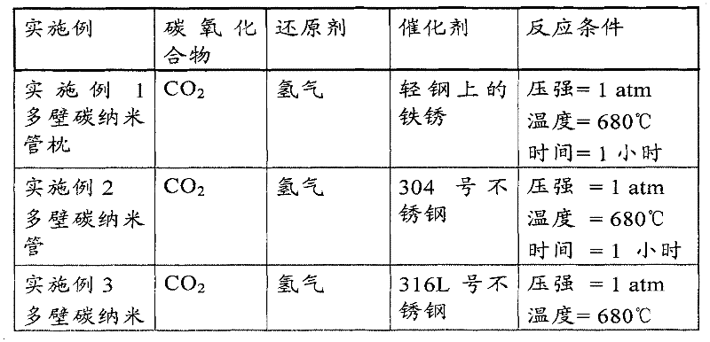

在以下部分中,每一实施例将通过附加信息详细介绍,同时将包括每个实施例产品的扫描电子显微镜图像。In the following sections, each example will be described in detail with additional information, and scanning electron microscope images of the product of each example will be included.
附图1中所描述的是所有实施例中所使用的实验装置。实验装置包括两个石英焙烧炉1和2,通过串联连接。产生这项安排是为了能够同时对每个焙烧炉执行单独的测试,潜在因素是在的不同的反应温度下及不同的催化剂,但具有相同的反应气体混合物以及压强。该安排允许在同时运行着两个焙烧炉是更加快速地测试。但是,只有单独焙烧炉需要有效操作时:所示的两个焙烧炉的安排是以实验的方便为前提的。样品被放入到其中一个焙烧炉。所有的测试是在间歇处理模式下运行。焙烧炉通过1至2个小时来达到所需温度并通过4至6个小时来冷却以便于样品可以被转移。通常情况下,实验只需要运行一个焙烧炉。附图1中所描述的所有组件及与其相关的管道、仪器仪表及其附属物一起被统称为“实验装置”,并将在下列实验的实施例中描述。Depicted in Figure 1 is the experimental setup used in all examples. The experimental setup consisted of two
在实施例中使用的气体的不同组分是:The different compositions of gases used in the examples are:
●二氧化碳(CO2),研究级,普莱克斯公司Carbon dioxide (CO 2 ), research grade, Praxair
●甲烷(CH4),研究级,普莱克斯公司Methane (CH 4 ), research grade, Praxair Corporation
●氮气(N2),标准级,普莱克斯公司Nitrogen (N 2 ), standard grade, Praxair
●氦气(He),研究级,法国液化空气公司● Helium (He), research grade, Air Liquide
●氢气(H2),研究级,普莱克斯公司Hydrogen (H 2 ), research grade, Praxair Corporation
如附图1所示,气体从气体供应装置6输送到混合阀7,气体在混合阀7处被测量并分配输送到焙烧炉1和2中。气体流过焙烧炉1和2,输送到冷冻冷凝器4(露点温度38℉),然后通过压缩机3并回到焙烧炉1的顶端。如果特定的实验需要清除焙烧炉内的惰性气体,真空泵5将被用来排空实验装置。As shown in FIG. 1 , the gas is delivered from the
第一焙烧炉1的温度通过固定在炉内约在其中心线位置的K型热电偶来测量。第二焙烧炉2的温度通过固定在焙烧炉的绝缘陶瓷钻井中的约在第二焙烧炉2的中心线处的K型热电偶来测量。记录的温度是在这些热电偶上显示的测量温度,虽然是在反应区中显示的温度,但这些温度并不是非常精确。在反应区的不同区域任何特定的实验设置在精确的记录反应温度上都将会出现类似的缺陷。但是,最终记录是用于记录测量温度,相关领域技术人员通过适当的实验和温度的改动可在相似的装置中产生相类似的结果。The temperature of the
没有尝试测量和控制再循环流动,同时产品的质量和反应速度似乎是与高容量压缩机或低容积泵是否被使用率无关。这些现象可能是由于各种情况下的流量是高于临界阈值导致。流量在优化设计和生产设施的运作中是重要因素,但在此处记录的测试中不是特别重要,这是由于实验装置的体积比催化剂和最终产生的固体碳产品的体积大得多。适当的测试为具体的生产设计确定了最佳流量,对于本领域技术人员来说这是容易确定的。No attempt was made to measure and control the recirculation flow, while product quality and response rates appeared to be independent of whether high capacity compressors or low capacity pumps were being used. These phenomena may be caused by the traffic being above the critical threshold in various cases. Flow is an important factor in optimizing the design and operation of a production facility, but was not particularly important in the tests documented here due to the much larger volume of the experimental setup compared to the volume of the catalyst and the resulting solid carbon product. Appropriate testing determines the optimum flow rate for a particular production design, as is readily determined by those skilled in the art.
通过实验,实验装置中的气体在压强会随着温度的上升突然开始迅速下降。一旦压强开始下降,温度随着催化剂和气体混合物的变花而变化。此处压强的突然下降可能是固态碳产品形成开始的指示。然后通过向反应装置添加额外的反应气体来维持压强。然后在短时间内,压强将开始上升,此时标志反应气体的添加将停止。压强降低和降低的时间似乎代表了碳纳米管生长的开始和持续时间和增长率。Through experiments, the pressure of the gas in the experimental device will suddenly start to drop rapidly as the temperature rises. Once the pressure begins to drop, the temperature changes as the catalyst and gas mixture change. A sudden drop in pressure here may be an indication of the onset of solid carbon product formation. The pressure is then maintained by adding additional reactive gas to the reaction unit. Then, for a short time, the pressure will start to rise, at which point the addition of the marker reactant gas will stop. The pressure decrease and the time of decrease seem to represent the onset and duration and growth rate of carbon nanotube growth.
启动程序遵循下面两种方法之一:在惰性气体(氦气或氮气)中加热,或在空气中加热。在惰性气体中加热的情况下,实验装置排空且清洗约5分钟,之后关闭真空泵5,同时像实验装置中填充惰性气体使其达到大气压。然后关闭惰性气体并打开焙烧炉使其开始加热循环。在空气中加热的情况下,焙烧炉启动时不需要清洗。只需打开焙烧炉并达到所需温度。The start-up procedure follows one of two methods: heating in an inert gas (helium or nitrogen), or heating in air. Under the condition of heating in an inert gas, the experimental device was evacuated and cleaned for about 5 minutes, and then the
当焙烧炉大约达到实验设置点温度时,撤离实验装置并清除反应气体混合物(通常是二氧化碳和还原气体的混合物)5分钟。然后实验装置中的反应气体达到大气压,同时温度继续增加直到反实验装置测量温度达到选定的实验温度When the roaster has reached approximately the experimental set point temperature, the experimental setup is evacuated and the reaction gas mixture (usually a mixture of carbon dioxide and reducing gas) is purged for 5 minutes. Then the reaction gas in the experimental device reaches atmospheric pressure, while the temperature continues to increase until the counter experimental device measured temperature reaches the selected experimental temperature
在实施例中,焙烧炉控制在固定的时间(通常为1小时),在这段时间内焙烧炉被关闭、清洗和冷却。关闭焙烧炉之后,打开真空泵5,排空反应气体并用惰性气体(氦气或氮气)清洗实验装置约5分钟,然后关闭真空泵5,用惰性气体填充实验装置使其达到大气压力,然后冷却。In an embodiment, the roaster is controlled for a fixed time (typically 1 hour), during which time the roaster is shut down, cleaned and cooled. After closing the roaster, turn on the
在实验中,没有观察到的基于惰性气体清除和冷却的CNTs产品质量上的差异。进一步的测试显示CNTs的性能通过冷却的气体混合物和冷却的速率被改性。根据此处实施例中记载的连续流动反应设备对于本领域技术人员来说是容易实现的。In the experiments, no differences in the product quality of CNTs based on inert gas scavenging and cooling were observed. Further tests showed that the properties of the CNTs were modified by cooling the gas mixture and the rate of cooling. Continuous flow reaction apparatus according to the examples described herein will be readily available to those skilled in the art.
实施例1Example 1
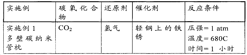
对于实施例1,用存在大量红色锈点的轻钢晶片的样品作为催化剂。将轻钢晶片放置于焙烧炉1约中心线处。启动真空泵5并用氦气清洗实验装置5分钟。5分钟后关闭真空泵5,打开压缩机3,并打开冷冻冷凝器4同时继续通入氦气直到压强达到680T时关闭气流。然后启动焙烧炉1.For Example 1, a sample of a light steel wafer presenting a large number of red rust spots was used as catalyst. The light steel wafer is placed on the approximately center line of the
当焙烧炉1的温度达到设置点温度680℃时,启动真空泵5,并用化学计量混合的二氧化碳和氢气反应气体清洗反应装置5分钟,其中该反应气体是通过被混合阀7控制的气体供应装置6供应的。5分钟后关闭真空泵5。当反应装置的达到760Torr压强时,停止供应反应气体。定期添加额外的反应气体使反应装置的表压维持在640Torr与760Torr之间。测试运行1小时后关闭焙烧炉1,启动真空泵5并用氦气清洗实验装置5分钟,其中氦气通过被混合阀7控制的气体供应装置6供应。然后关闭真空泵5,继续通入氦气清洗气直到反应装置中的表压达到740Torr。然后移开冷却焙烧炉1.When the temperature of the
焙烧炉1冷却后移出钢样品。附图2中展示的是移出之后样品的照片;注意到在基底上生长的“森林”形态。该森林形态是由碳纳米管“波形”组成。附图3展示了700x放大率下相同样品的电镜扫描图。附图4展示了18,000x放大率下相同样品的电镜扫描图并显示出典型的“枕形“的详细信息。CNTs的大小(几十到几百纳米直径)表示他们最有可能是多壁纳米管。注意到在附图4中可看到催化剂在每个碳纳米管的增长顶端。增长顶端的平均直径似乎是与之相关的碳纳米管直径的约1.2到1.3倍。附图5描述的是附图4中CNTs的元素分析图,指出CNTs是由碳及少量铁和氧组成的,可能是由于嵌入CNTs增长顶端的催化剂颗粒导致。After the
实施例2Example 2
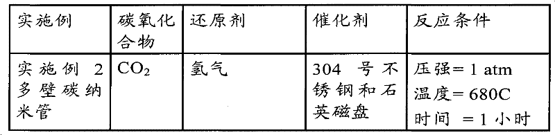
对于实施例2,移动石英磁盘样品使之平铺在304号不锈钢晶片上,其中不锈钢晶片作为催化剂。304号不锈钢催化剂晶片放到焙烧炉1中位于约中心线处。开启真空泵5并用氦气清洗实验装置5分钟。5分钟后关闭真空泵5,开启压缩机3,开启冷冻冷凝器4并继续通入氦气直到压强达到680Torr,此时停止气体流入。然后开启焙烧炉1。For Example 2, samples of quartz disks were moved so that they were spread flat on 304 stainless steel wafers, which served as catalysts. A 304 stainless steel catalyst wafer was placed in the
当焙烧炉1温度达到设定点温度680℃时,启动真空泵5,并用化学计量混合的二氧化碳和氢气反应气体清洗反应装置5分钟,其中该反应气体是通过被混合阀7控制的气体供应装置6供应的。5分钟后关闭真空泵5。当反应装置的达到760Torr压强时,停止供应反应气体。1.定期添加额外的反应气体使反应装置的表压维持在640到760Torr之间。测试运行1小时后关闭焙烧炉1,启动真空泵5并用氦气清洗实验装置5分钟,其中氦气通过被混合阀7控制的气体供应装置6供应。然后关闭真空泵5,继续通入氦气清洗气直到反应装置中的表压达到740Torr。然后移开并冷却焙烧炉1。When the temperature of the
焙烧炉1冷却后从焙烧炉1中移出钢样品。CNTs的纤维网片生长在石英与晶片之间。部分CNT纤维网片粘附在石英和钢催化剂晶片表面。附图6展示了10,000x放大率下样品的电镜扫描图,附图7中展示了100,000x放大率下样品的电镜扫描图。CNTs的大小(几十到几百纳米直径)表示他们可能是多壁纳米管。The steel sample was removed from the
实施例3Example 3
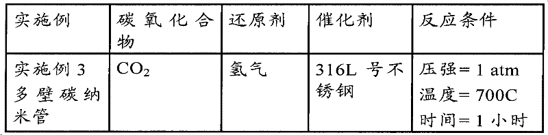
对于实施例3,用316L号不锈钢晶片作为催化剂。将316L号不锈钢晶片放到焙烧炉1中位于约中心线处。开启压缩机3,打开冷冻冷凝器4,开启真空泵5,将含有氦气的清洗气体引入实验装置中,其中清洗气体是通过被混合阀7控制的气体提供装置6供应的。清洗5分钟后关闭真空泵5同时继续通入氦气清洗气体知道实验装置中的表压达到680Torr时关闭清洗气体流For Example 3, a 316L stainless steel wafer was used as the catalyst. A 316L stainless steel wafer was placed in
当焙烧炉1温度达到700℃时,启动真空泵5,并用化学计量混合的二氧化碳和氢气反应气体通过反应装置,其中反应气体是通过被混合阀7控制的气体供应装置6供应。5分钟后关闭真空泵5同时继续通入反应气体直到实验装置的表压达到730Torr,此时减少反应气体流量至较低的足以维持压强在700Torr到730Torr之间的流量。实验装置运行1小时后关闭焙烧炉1,开启真空泵5同时用氦气清洗实验装置5分钟,其中氦气通过被混合阀7控制的气体供应装置6提供。然后关闭真空泵5同时继续通入氦气直到实验装置中的表压达到760Torr。然后移开并冷却焙烧炉1。When the temperature of the
焙烧炉1冷却后从焙烧炉1中移出钢样品。在冷却焙烧炉1后从焙烧炉1中移出316L号不锈钢晶片。附图8是316L号不锈钢晶片的照片。注意到固态碳产品,其中碳纳米管仅生长在晶片的一部分上。导致该现象产生的原因还不明确。附图9描述的是2,500x放大率下晶片上CNT森林形态区域的图像,附图10是10,000x放大率下相同的CNT森林形态区域的图像。管得直径显示出CNTs更可能是多壁的。The steel sample was removed from the
实施例4Example 4
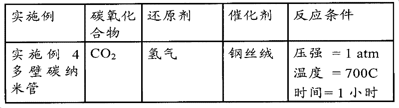
对于实施例4,样品轻钢丝绒作为催化剂。轻钢丝绒放置于焙烧炉1中位于约中心线处并在空气中加热。开启焙烧炉1,打开压缩机3同时打开冷冻冷凝器4.当焙烧炉1温度达到645℃(即,在焙烧炉1达到设置点温度700℃之前)开启真空泵5,并将通过被混合阀7控制的气体供应装置6供应的化学计量混合的二氧化碳和氢气通入实验装置5分钟。5分钟结束后关闭真空泵5,同时继续通入气体直到实验装置的表压达到530Torr时降低反应气体流量至足以维持压强在500Torr到530Torr之间的较低的流量。实验装置运行1小时后关闭焙烧炉1,开启真空泵5同时用氦气清洗实验装置5分钟,其中氦气通过被混合阀7控制的气体供应装置6提供。然后关闭真空泵5并继续通入氦气直到实验装置中的表压达到760Torr。然后移开冷却焙烧炉1。For Example 4, sample light steel wool as catalyst. Lightweight steel wool is placed in the
冷却焙烧炉1后移出与固态碳产品一起的钢丝绒。附图11是钢丝绒样品的照片。注意到固态碳产品的粉末状黑带,通过采样和SEM检测产生如附图12中描述的800x放大率下的粉末的离子图像。颗粒是包括粉状黑带的大量波浪形态的一个“波形”。附图13描述的是120,000x放大率下的相同“波形”的图像。该直径表明CNTs可能是多壁的。The steel wool together with the solid carbon product is removed after cooling the
实施例5Example 5
对于实施例5,样品316号不锈钢丝作为催化剂。将316号不锈钢丝放置于焙烧炉1中位于约中心线处并在空气中加热。开启焙烧炉1并打开冷冻冷凝器4。开启真空泵5,并将通过被混合阀7控制的气体供应装置6供应的包括化学计量混合的二氧化碳和氢气的反应气体用来清洗实验装置5分钟。5分钟后关闭真空泵5,打开压缩机3,同时继续通入反应气体混合物直到实验装置中的表压达到589Torr时停止反应气体流入。实验装置运行1小时候关闭焙烧炉1,开启真空泵5同时用氦气清洗实验装置5分钟,其中氦气通过被混合阀7控制的气体供应装置6提供。然后关闭真空泵5同时继续通入氦气直到实验装置中的表压达到700Torr。然后移开冷却焙烧炉1。For Example 5, sample 316 stainless steel wire was used as the catalyst. A 316 gauge stainless steel wire was placed in the
冷却焙烧炉1后从焙烧炉1中移出钢丝。附图14是在本实施例中石墨板上的在表面生长固态碳产品的钢丝样品的图片。石墨板样品的图像是利用SEM产生的如附图15所示的在7,000x放大率下的石墨板的图像和附图16所示的在50,000x放大率下的石墨板的详细图像。The steel wire is removed from the
实施例6Example 6
对于实施例6,304号不锈钢晶片作为催化剂。将石英磁盘样品放置于钢晶片的上表面上。304号不锈钢晶片与石英磁盘一起放置于焙烧炉1中约中心线处。开启真空泵5,并将通过被混合阀7控制的气体供应装置6供应的包括化学计量混合的二氧化碳和氢气的反应气体用来清洗实验装置5分钟。5分钟后关闭真空泵5,打开压缩机3,开启冷却冷凝器4同时继续通入氦气直到实验装置中的压强达到680Torr时停止反应气体流入。然后移开冷却焙烧炉1。For Example 6, 304 stainless steel wafers were used as catalysts. A sample of the quartz disk was placed on the upper surface of the steel wafer. A 304 stainless steel wafer was placed in the
当焙烧炉1温度达到设置点温度650℃时,启动真空泵5,并用通过被混合阀7控制的气体供应装置6供应的化学计量混合的二氧化碳和氢气反应气体来清洗实验装置5分钟。5分钟后关闭真空泵5。当实验装置达到730Torr表压时,停止反应气体。定期的添加额外的反应气体使反应装置的压强保持在640Torr到760Torr之间。测试运行1小时后关闭焙烧炉1,启动真空泵5并用氦气清洗实验装置5分钟,其中氦气通过被混合阀7控制的气体供应装置6供应。然后关闭真空泵5,并继续通入氦气清洗气直到反应装置中的表压达到740Torr。然后移开冷却焙烧炉1。When the
附图17是在石墨板表面生长的样品的图片。石墨板样品的图像是利用SEM产生的如附图18所示的在778x放大率下的石墨板的图像。在附图18中所示的波形包括纤维形态。图19所示的是在11000x放大率下的一个波形的图像,其中可以看到高度缠结的碳纳米管结构。附图20的是在7000x放大率下,包括如在附图19中所示的同一波形的一些碳纳米管的详细信息。Figure 17 is a picture of a sample grown on the surface of a graphite plate. The image of the graphite plate sample is an image of the graphite plate at 778x magnification produced using a SEM as shown in Figure 18 . The waveform shown in Figure 18 includes fiber morphology. Shown in Figure 19 is an image of a waveform at 11000x magnification, where highly entangled carbon nanotube structures can be seen. Figure 20 is a detail of some carbon nanotubes including the same waveform as shown in Figure 19 at 700Ox magnification.
因此,本发明具有超过现有发明的技术优势。虽然说本发明方法的实施方案已经被描述过,同时各种修正和改进对于本领域技术人员是显而易见的。这些替换、修正和改进都将作为本次公开的一部分,并都落入到本发明的原理和范围内。Therefore, the present invention has technical advantages over prior inventions. While embodiments of the method of the invention have been described, various modifications and improvements will be apparent to those skilled in the art. All these replacements, modifications and improvements shall be considered as a part of this disclosure, and all shall fall within the principle and scope of the present invention.
Claims (49)
Applications Claiming Priority (3)
| Application Number | Priority Date | Filing Date | Title |
|---|---|---|---|
| US17019909P | 2009-04-17 | 2009-04-17 | |
| US61/170,199 | 2009-04-17 | ||
| PCT/US2010/029934 WO2010120581A1 (en) | 2009-04-17 | 2010-04-05 | Method for producing solid carbon by reducing carbon oxides |
Publications (2)
| Publication Number | Publication Date |
|---|---|
| CN102459727A true CN102459727A (en) | 2012-05-16 |
| CN102459727B CN102459727B (en) | 2015-04-15 |
Family
ID=42982794
Family Applications (1)
| Application Number | Title | Priority Date | Filing Date |
|---|---|---|---|
| CN201080027181.7A Active CN102459727B (en) | 2009-04-17 | 2010-04-05 | Method for reducing carbon oxides to solid carbon |
Country Status (19)
| Country | Link |
|---|---|
| US (3) | US8679444B2 (en) |
| EP (1) | EP2419553B1 (en) |
| JP (2) | JP5658739B2 (en) |
| KR (1) | KR101753918B1 (en) |
| CN (1) | CN102459727B (en) |
| AU (1) | AU2010236807B2 (en) |
| BR (1) | BRPI1013704A2 (en) |
| CA (1) | CA2758694C (en) |
| CL (1) | CL2011002588A1 (en) |
| CO (1) | CO6440587A2 (en) |
| EA (1) | EA028873B1 (en) |
| EC (1) | ECSP11011404A (en) |
| MX (3) | MX2011010864A (en) |
| MY (1) | MY160277A (en) |
| NZ (1) | NZ595714A (en) |
| PE (1) | PE20121017A1 (en) |
| PH (1) | PH12015501928B1 (en) |
| SG (1) | SG175115A1 (en) |
| WO (1) | WO2010120581A1 (en) |
Cited By (10)
| Publication number | Priority date | Publication date | Assignee | Title |
|---|---|---|---|---|
| CN104098085A (en) * | 2014-07-18 | 2014-10-15 | 信阳师范学院 | Method for preparing three-dimensional carbon nano tube net |
| CN104603051A (en) * | 2012-09-18 | 2015-05-06 | 埃克森美孚上游研究公司 | Reactor system for the production of carbon allotropes |
| CN104936894A (en) * | 2013-01-17 | 2015-09-23 | 沙特基础工业公司 | Carbon nano-tube production from carbon dioxide |
| CN104936893A (en) * | 2012-11-29 | 2015-09-23 | 赛尔斯通股份有限公司 | Reactor and method for producing solid carbon materials |
| CN105339300A (en) * | 2013-06-27 | 2016-02-17 | 日本瑞翁株式会社 | Manufacturing method of carbon nanotubes |
| CN105452533A (en) * | 2013-05-30 | 2016-03-30 | 曼彻斯特大学 | Electrochemical process for production of graphene |
| CN106660799A (en) * | 2014-06-09 | 2017-05-10 | 卡纳图有限公司 | Catalyst particle and method for producing thereof |
| CN108468037A (en) * | 2018-02-26 | 2018-08-31 | 武汉大学 | Femtosecond laser predissociation device and chemical vapor depsotition equipment |
| CN115515895A (en) * | 2020-05-19 | 2022-12-23 | 国立大学法人静冈大学 | Reaction system, method for trapping solid carbon, method for producing hydrogen-containing gas, catalyst set, and catalyst for trapping solid carbon |
| WO2023116850A1 (en) * | 2021-12-23 | 2023-06-29 | 南京大学 | Method for directly converting carbon dioxide into solid carbon by utilizing photochemical reaction |
Families Citing this family (90)
| Publication number | Priority date | Publication date | Assignee | Title |
|---|---|---|---|---|
| US8535791B2 (en) * | 2006-06-30 | 2013-09-17 | The University Of Akron | Aligned carbon nanotube-polymer materials, systems and methods |
| CA2758694C (en) | 2009-04-17 | 2017-05-23 | Seerstone Llc | Method for producing solid carbon by reducing carbon oxides |
| US10005672B2 (en) | 2010-04-14 | 2018-06-26 | Baker Hughes, A Ge Company, Llc | Method of forming particles comprising carbon and articles therefrom |
| US9205531B2 (en) | 2011-09-16 | 2015-12-08 | Baker Hughes Incorporated | Methods of fabricating polycrystalline diamond, and cutting elements and earth-boring tools comprising polycrystalline diamond |
| JP5555944B2 (en) * | 2010-11-16 | 2014-07-23 | 学校法人早稲田大学 | Method for producing carbon nanotube |
| SG11201400649XA (en) | 2011-09-16 | 2014-04-28 | Baker Hughes Inc | Methods of fabricating polycrystalline diamond, and cutting elements and earth-boring tools comprising polycrystalline diamond |
| RU2497752C2 (en) * | 2011-11-29 | 2013-11-10 | Инфра Текнолоджис Лтд. | Method of obtaining long carbon nanopipes and device for thereof realisation |
| CA2858725C (en) | 2011-12-12 | 2018-09-18 | Exxonmobil Upstream Research Company | Method and systems for forming carbon nanotubes |
| TW201341609A (en) * | 2011-12-12 | 2013-10-16 | Exxonmobil Upstream Res Co | Methods and system for forming carbon nanotubes |
| TWI588307B (en) * | 2011-12-30 | 2017-06-21 | 艾克頌美孚上游研究公司 | Method and systems for forming carbon nanotubes |
| WO2013158157A1 (en) * | 2012-04-16 | 2013-10-24 | Seerstone Llc | Methods and reactors for producing solid carbon nanotubes, solid carbon clusters, and forests |
| CN104284861A (en) * | 2012-04-16 | 2015-01-14 | 赛尔斯通股份有限公司 | Methods for treating offgas containing carbon oxides |
| EP2838838A4 (en) * | 2012-04-16 | 2015-10-21 | Seerstone Llc | Methods and systems for capturing and sequestering carbon and for reducing the mass of carbon oxides in a waste gas stream |
| JP2015520717A (en) * | 2012-04-16 | 2015-07-23 | シーアストーン リミテッド ライアビリティ カンパニー | Method for using a metal catalyst in a carbon oxide catalytic converter |
| US9090472B2 (en) | 2012-04-16 | 2015-07-28 | Seerstone Llc | Methods for producing solid carbon by reducing carbon dioxide |
| NO2749379T3 (en) * | 2012-04-16 | 2018-07-28 | ||
| MX2014012548A (en) * | 2012-04-16 | 2015-04-10 | Seerstone Llc | Methods and structures for reducing carbon oxides with non-ferrous catalysts. |
| TW201410596A (en) | 2012-04-17 | 2014-03-16 | 艾克頌美孚上游研究公司 | Feedstocks for forming carbon allotropes |
| TWI570072B (en) | 2012-04-18 | 2017-02-11 | 艾克頌美孚上游研究公司 | Removing carbon nanotubes from a water stream |
| TW201400407A (en) * | 2012-04-18 | 2014-01-01 | Exxonmobil Upstream Res Co | Manufacture of a catalyst for forming a carbon allotrope |
| TWI627130B (en) * | 2012-04-18 | 2018-06-21 | 美商艾克頌美孚上游研究公司 | Removing carbon nanotubes from a continuous reactor effluent |
| JP6283353B2 (en) * | 2012-04-23 | 2018-02-21 | シーアストーン リミテッド ライアビリティ カンパニー | Carbon nanotubes with bimodal size distribution |
| US9896341B2 (en) | 2012-04-23 | 2018-02-20 | Seerstone Llc | Methods of forming carbon nanotubes having a bimodal size distribution |
| MX2015000515A (en) | 2012-07-12 | 2015-10-12 | Seerstone Llc | Solid carbon products comprising carbon nanotubes and methods of forming same. |
| US10815124B2 (en) | 2012-07-12 | 2020-10-27 | Seerstone Llc | Solid carbon products comprising carbon nanotubes and methods of forming same |
| US9598286B2 (en) | 2012-07-13 | 2017-03-21 | Seerstone Llc | Methods and systems for forming ammonia and solid carbon products |
| US9779845B2 (en) | 2012-07-18 | 2017-10-03 | Seerstone Llc | Primary voltaic sources including nanofiber Schottky barrier arrays and methods of forming same |
| PT106779A (en) | 2013-02-13 | 2014-08-13 | José Jo O Santana Campos Rodrigues | ELECTROLYTEER AND PRODUCTION PROCESS OF SYNTHESIS GAS, BY ELECTROLYSIS OF WATER, USING GRAPHITE / CARBON ELECTRODES |
| EP3113881A4 (en) * | 2013-03-15 | 2018-01-10 | Seerstone LLC | Compositions of matter comprising nanocatalyst structures, systems comprising nanocatalyst structures, and related methods |
| US9783421B2 (en) | 2013-03-15 | 2017-10-10 | Seerstone Llc | Carbon oxide reduction with intermetallic and carbide catalysts |
| US20160039677A1 (en) * | 2013-03-15 | 2016-02-11 | Seerstone Llc | Direct combustion heating |
| WO2014150944A1 (en) * | 2013-03-15 | 2014-09-25 | Seerstone Llc | Methods of producing hydrogen and solid carbon |
| WO2014151138A1 (en) * | 2013-03-15 | 2014-09-25 | Seerstone Llc | Reactors, systems, and methods for forming solid products |
| WO2014151119A2 (en) * | 2013-03-15 | 2014-09-25 | Seerstone Llc | Electrodes comprising nanostructured carbon |
| EP3129133B1 (en) | 2013-03-15 | 2024-10-09 | Seerstone LLC | Systems for producing solid carbon by reducing carbon oxides |
| US20150050816A1 (en) * | 2013-08-19 | 2015-02-19 | Korea Atomic Energy Research Institute | Method of electrochemically preparing silicon film |
| US10024110B2 (en) * | 2013-12-18 | 2018-07-17 | Halliburton Energy Services, Inc. | Earth-boring drill bits with nanotube carpets |
| WO2015119618A1 (en) * | 2014-02-07 | 2015-08-13 | Empire Technology Development Llc | Method of producing graphene from a hydrocarbon gas and liquid metal catalysts |
| JP6162631B2 (en) * | 2014-03-14 | 2017-07-12 | トヨタ自動車株式会社 | Method for producing carbon nanofiber |
| US11298682B2 (en) * | 2014-05-12 | 2022-04-12 | North Carolina State University | Activated metal low temperature reaction processes and products |
| MY185388A (en) * | 2015-08-26 | 2021-05-17 | Hazer Group Ltd | A process of controlling the morphology of graphite |
| US10000413B1 (en) | 2015-12-16 | 2018-06-19 | The United States Of America As Represented By The Administrator Of The National Aeronautics And Space Administration | Carbon-enhanced cement clinker |
| US11171324B2 (en) | 2016-03-15 | 2021-11-09 | Honda Motor Co., Ltd. | System and method of producing a composite product |
| US11383213B2 (en) | 2016-03-15 | 2022-07-12 | Honda Motor Co., Ltd. | System and method of producing a composite product |
| KR101938874B1 (en) * | 2016-07-20 | 2019-01-15 | 주식회사 참트론 | The heat-treatment device for synthesis of high quality graphene |
| US11752459B2 (en) | 2016-07-28 | 2023-09-12 | Seerstone Llc | Solid carbon products comprising compressed carbon nanotubes in a container and methods of forming same |
| US10995000B2 (en) | 2016-10-19 | 2021-05-04 | Vanderbilt University | Nanostructured carbon materials and methods of making and use thereof |
| KR102098989B1 (en) | 2017-01-04 | 2020-04-08 | 주식회사 엘지화학 | Control method for tensile strength of cnt fiber aggregates |
| US20190359488A1 (en) * | 2017-01-10 | 2019-11-28 | Seerstone Llc | Apparatus and methods of forming solid carbon |
| US11081684B2 (en) | 2017-05-24 | 2021-08-03 | Honda Motor Co., Ltd. | Production of carbon nanotube modified battery electrode powders via single step dispersion |
| US11383196B2 (en) * | 2017-06-02 | 2022-07-12 | Monalaser, Llc | Method and apparatus for decomposing carbon dioxide gas |
| US10658651B2 (en) | 2017-07-31 | 2020-05-19 | Honda Motor Co., Ltd. | Self standing electrodes and methods for making thereof |
| US20190036102A1 (en) | 2017-07-31 | 2019-01-31 | Honda Motor Co., Ltd. | Continuous production of binder and collector-less self-standing electrodes for li-ion batteries by using carbon nanotubes as an additive |
| US11121358B2 (en) | 2017-09-15 | 2021-09-14 | Honda Motor Co., Ltd. | Method for embedding a battery tab attachment in a self-standing electrode without current collector or binder |
| US11201318B2 (en) | 2017-09-15 | 2021-12-14 | Honda Motor Co., Ltd. | Method for battery tab attachment to a self-standing electrode |
| KR102341186B1 (en) | 2018-12-21 | 2021-12-21 | 퍼포먼스 나노카본, 아이엔씨. | In situ production and functionalization of carbon materials via gas-liquid mass transfer and their use |
| US11535517B2 (en) | 2019-01-24 | 2022-12-27 | Honda Motor Co., Ltd. | Method of making self-standing electrodes supported by carbon nanostructured filaments |
| US12142771B2 (en) | 2019-01-30 | 2024-11-12 | Honda Motor Co., Ltd. | Flexible battery as an integration platform for wearable sensors and processing/transmitting devices |
| US12381275B2 (en) | 2019-01-30 | 2025-08-05 | Honda Motor Co., Ltd. | Stretchable and flexible lithium ion battery |
| US11325833B2 (en) | 2019-03-04 | 2022-05-10 | Honda Motor Co., Ltd. | Composite yarn and method of making a carbon nanotube composite yarn |
| US11352258B2 (en) | 2019-03-04 | 2022-06-07 | Honda Motor Co., Ltd. | Multifunctional conductive wire and method of making |
| CA3077850A1 (en) * | 2019-04-04 | 2020-10-04 | Cvmr Energy Metals Inc. | Processes for converting carbon dioxide |
| WO2020264191A1 (en) * | 2019-06-27 | 2020-12-30 | Cornell University | Preparation of expanded graphite by physical shearing |
| WO2021002770A1 (en) * | 2019-07-04 | 2021-01-07 | Автономная некоммерческая образовательная организация высшего образования "Сколковский институт науки и технологий" | Method for producing graphene |
| US11539042B2 (en) | 2019-07-19 | 2022-12-27 | Honda Motor Co., Ltd. | Flexible packaging with embedded electrode and method of making |
| CN114787080A (en) * | 2019-09-17 | 2022-07-22 | 新加坡国立大学 | waste treatment system |
| AU2020375635A1 (en) * | 2019-10-28 | 2022-06-16 | Seerstone Llc | Thermal treatment of coke produced from carbon oxides |
| KR102808115B1 (en) * | 2019-11-26 | 2025-05-16 | 주식회사 엘지화학 | Preparing method for carbon nanotube and carbon nanotube prepared therby |
| RU2756555C1 (en) * | 2020-05-12 | 2021-10-01 | Федеральное государственное бюджетное учреждение науки Федеральный исследовательский центр химической физики им. Н.Н. Семенова Российской академии наук (ФИЦ ХФ РАН) | Method for producing iron carbide nanopowder |
| US20220169835A1 (en) | 2020-12-02 | 2022-06-02 | The Goodyear Tire & Rubber Company | Pneumatic tire and rubber composition including carbon dioxide-generated carbon reinforcing filler |
| RU2770102C1 (en) * | 2020-12-28 | 2022-04-14 | Федеральное государственное бюджетное учреждение науки Федеральный исследовательский центр химической физики им. Н.Н. Семенова Российской академии наук (ФИЦ ХФ РАН) | Method for producing iron carbide nanopowder |
| DE102021104746B3 (en) * | 2021-02-26 | 2022-08-25 | Obrist Technologies Gmbh | Plant and method for reducing the carbon dioxide content in atmospheric air |
| US11747311B2 (en) | 2021-03-22 | 2023-09-05 | Honeywell International Inc. | Hydrocarbon byproduct monitoring of fibrous substrates |
| US11746007B2 (en) | 2021-03-22 | 2023-09-05 | Honeywell International Inc. | Fibrous substrates for hydrogen generation |
| JP7748608B2 (en) * | 2021-09-16 | 2025-10-03 | Solution Creators株式会社 | Method and apparatus for recovering solid carbon from biogas |
| US12397585B2 (en) | 2021-12-20 | 2025-08-26 | The Goodyear Tire & Rubber Company | Tread rubber composition with majority renewable content |
| US12351717B2 (en) | 2021-12-20 | 2025-07-08 | The Goodyear Tire & Rubber Company | Tread rubber composition with majority renewable content |
| EP4453102A1 (en) * | 2021-12-21 | 2024-10-30 | Soane Labs, LLC | Systems and methods for producing carbon solids |
| AU2023231849A1 (en) * | 2022-03-07 | 2024-10-03 | Jfe Steel Corporation | Method and apparatus for recovering carbon from carbon-containing gas |
| US11548782B1 (en) | 2022-06-28 | 2023-01-10 | Halliburton Energy Services, Inc. | Using converted hydrogen and solid carbon from captured methane to power wellbore equipment |
| EP4310140A1 (en) | 2022-07-22 | 2024-01-24 | The Goodyear Tire & Rubber Company | Tire component with a majority renewable content |
| JP7773451B2 (en) * | 2022-09-15 | 2025-11-19 | 株式会社東芝 | Immobilization System |
| US20240199862A1 (en) | 2022-12-16 | 2024-06-20 | The Goodyear Tire & Rubber Company | Sustainable tire produced with high recycled/renewable raw material content |
| WO2024154412A1 (en) * | 2023-01-19 | 2024-07-25 | Jfeスチール株式会社 | Method for producing coke |
| EP4655102A1 (en) * | 2023-01-26 | 2025-12-03 | Czero, Inc. | Heat integrated chemical looping formation of carbon and hydrogen |
| US12113254B1 (en) | 2023-05-15 | 2024-10-08 | Halliburton Energy Services, Inc. | Combined hydrogen supply and fuel cell processes for increased efficiency of electricity generation |
| WO2024263929A2 (en) * | 2023-06-22 | 2024-12-26 | Czero, Inc. | Carbon formation chemical looping using oxygen |
| CN117902551B (en) * | 2024-03-19 | 2024-05-14 | 西南石油大学 | A reaction device for producing hydrogen from methane without carbon emission |
| WO2025227073A1 (en) * | 2024-04-26 | 2025-10-30 | Czero, Inc. | Solid carbon products and methods of producing solid carbon |
| CN119612504B (en) * | 2025-02-12 | 2025-04-18 | 四川惠士特能源装备有限公司 | A method and system for preparing graphene based on natural gas containing carbon dioxide |
Citations (3)
| Publication number | Priority date | Publication date | Assignee | Title |
|---|---|---|---|---|
| US20050002851A1 (en) * | 2002-11-26 | 2005-01-06 | Mcelrath Kenneth O. | Carbon nanotube particulates, compositions and use thereof |
| US20050074392A1 (en) * | 2002-07-31 | 2005-04-07 | Yuemei Yang | Method for making single-wall carbon nanotubes using supported catalysts |
| CN1781843A (en) * | 2004-11-02 | 2006-06-07 | 三星Sdi株式会社 | Carbon nanosphere,method of preparing the same,catalyst and fuel cell |
Family Cites Families (391)
| Publication number | Priority date | Publication date | Assignee | Title |
|---|---|---|---|---|
| US3172774A (en) | 1965-03-09 | Method of forming composite graphite coated article | ||
| US1478730A (en) | 1922-03-09 | 1923-12-25 | Roy H Brownlee | Special carbon black |
| US1746464A (en) | 1925-07-21 | 1930-02-11 | Fischer Franz | Process for the production of paraffin-hydrocarbons with more than one carbon atom |
| US1735925A (en) | 1925-08-28 | 1929-11-19 | Selden Co | Process of producing reduction products of carbon dioxide |
| US1964744A (en) | 1930-02-20 | 1934-07-03 | William W Odell | Process of making carbon black |
| US2429980A (en) | 1942-11-27 | 1947-11-04 | Lion Oil Co | Process of conducting chemical reactions |
| US2440424A (en) | 1944-05-04 | 1948-04-27 | Columbian Carbon | Manufacture of carbon black |
| US2731328A (en) | 1950-05-29 | 1956-01-17 | Phillips Petroleum Co | Carbon black manufacture |
| US2811653A (en) | 1953-05-22 | 1957-10-29 | Rca Corp | Semiconductor devices |
| US3094634A (en) | 1953-06-30 | 1963-06-18 | Rca Corp | Radioactive batteries |
| US2837666A (en) | 1953-07-24 | 1958-06-03 | Ernest G Linder | Radioactive voltage source employing a gaseous dielectric medium |
| US2796327A (en) | 1953-08-21 | 1957-06-18 | Phillips Petroleum Co | Process for producing carbon black, acrylonitrile and hydrogen cyanide |
| US2745973A (en) | 1953-11-02 | 1956-05-15 | Rca Corp | Radioactive battery employing intrinsic semiconductor |
| US2800616A (en) | 1954-04-14 | 1957-07-23 | Gen Electric | Low voltage electrolytic capacitor |
| US2976433A (en) | 1954-05-26 | 1961-03-21 | Rca Corp | Radioactive battery employing semiconductors |
| US2796331A (en) | 1954-06-09 | 1957-06-18 | Pittsburgh Coke & Chemical Co | Process for making fibrous carbon |
| US2819414A (en) | 1954-08-02 | 1958-01-07 | Rca Corp | Radioactive battery employing stacked semi-conducting devices |
| US3249830A (en) | 1962-01-09 | 1966-05-03 | Electro Organics Inc | Organic semi-conductor materials and contact rectifier employing the same |
| US3378345A (en) | 1965-03-22 | 1968-04-16 | Union Carbide Corp | Process for producing pyrolytic graphite whiskers |
| US3488394A (en) | 1966-05-11 | 1970-01-06 | Fmc Corp | Oxidation of olefinic compounds to glycols |
| US3634999A (en) | 1970-04-08 | 1972-01-18 | Allied Chem | Method for recovering dust produced in sodium carbonate manufacture |
| US3714474A (en) | 1970-10-07 | 1973-01-30 | Ecc Corp | Electron-voltaic effect device |
| US3771959A (en) | 1971-10-21 | 1973-11-13 | Nasa | Catalyst cartridge for carbon dioxide reduction unit |
| US4126000A (en) | 1972-05-12 | 1978-11-21 | Funk Harald F | System for treating and recovering energy from exhaust gases |
| US4200554A (en) | 1974-04-25 | 1980-04-29 | E. I. Du Pont De Nemours & Company | Barium- and ruthenium-containing perovskite catalysts |
| US3905748A (en) | 1974-06-24 | 1975-09-16 | Robertshaw Controls Co | Primary control system for furnaces |
| US4024420A (en) | 1975-06-27 | 1977-05-17 | General Electric Company | Deep diode atomic battery |
| US4197281A (en) | 1975-12-17 | 1980-04-08 | Texaco Development Corporation | Production of ammonia synthesis gas from solid carbonaceous fuels |
| US5122332A (en) | 1977-04-13 | 1992-06-16 | Virginia Russell | Protecting organisms and the environment from harmful radiation by controlling such radiation and safely disposing of its energy |
| US4710483A (en) | 1977-07-21 | 1987-12-01 | Trw Inc. | Novel carbonaceous material and process for producing a high BTU gas from this material |
| US4900368A (en) | 1984-03-12 | 1990-02-13 | Brotz Gregory R | Foamed energy cell |
| US4628143A (en) | 1984-03-12 | 1986-12-09 | Brotz Gregory R | Foamed nuclear cell |
| US4746458A (en) | 1984-03-12 | 1988-05-24 | Brotz Gregory R | Photovoltaic material |
| US6375917B1 (en) | 1984-12-06 | 2002-04-23 | Hyperion Catalysis International, Inc. | Apparatus for the production of carbon fibrils by catalysis and methods thereof |
| US5707916A (en) | 1984-12-06 | 1998-01-13 | Hyperion Catalysis International, Inc. | Carbon fibrils |
| US4663230A (en) | 1984-12-06 | 1987-05-05 | Hyperion Catalysis International, Inc. | Carbon fibrils, method for producing same and compositions containing same |
| US5165909A (en) | 1984-12-06 | 1992-11-24 | Hyperion Catalysis Int'l., Inc. | Carbon fibrils and method for producing same |
| US4602477A (en) | 1985-06-05 | 1986-07-29 | Air Products And Chemicals, Inc. | Membrane-aided distillation for carbon dioxide and hydrocarbon separation |
| US4727207A (en) | 1986-07-02 | 1988-02-23 | Standard Oil Company | Process for converting methane and/or natural gas to more readily transportable materials |
| US4725346A (en) | 1986-07-25 | 1988-02-16 | Ceramatec, Inc. | Electrolyte assembly for oxygen generating device and electrodes therefor |
| JPH0192425A (en) | 1987-09-30 | 1989-04-11 | Nkk Corp | Production of carbon fiber with vapor growth |
| WO1990007797A1 (en) | 1988-12-29 | 1990-07-12 | Cota Albert O | A self-sustaining power module |
| US5008579A (en) | 1989-03-03 | 1991-04-16 | E. F. Johnson Co. | Light emitting polymer electrical energy source |
| ZA907803B (en) | 1989-09-28 | 1991-07-31 | Hyperion Catalysis Int | Electrochemical cells and preparing carbon fibrils |
| DE3937558C2 (en) | 1989-11-11 | 1997-02-13 | Leybold Ag | Cathode sputtering device |
| US5413866A (en) | 1990-10-23 | 1995-05-09 | Baker; R. Terry K. | High performance carbon filament structures |
| US5149584A (en) | 1990-10-23 | 1992-09-22 | Baker R Terry K | Carbon fiber structures having improved interlaminar properties |
| US5133190A (en) | 1991-01-25 | 1992-07-28 | Abdelmalek Fawzy T | Method and apparatus for flue gas cleaning by separation and liquefaction of sulfur dioxide and carbon dioxide |
| US5260621A (en) | 1991-03-18 | 1993-11-09 | Spire Corporation | High energy density nuclide-emitter, voltaic-junction battery |
| FR2679382B1 (en) | 1991-07-15 | 1996-12-13 | Accumulateurs Fixes | ELECTROCHEMICAL GENERATOR OF HIGH SPECIFIC MASS ENERGY. |
| JP2687794B2 (en) | 1991-10-31 | 1997-12-08 | 日本電気株式会社 | Graphite fiber with cylindrical structure |
| US20020085974A1 (en) | 1992-01-15 | 2002-07-04 | Hyperion Catalysis International, Inc. | Surface treatment of carbon microfibers |
| US5624542A (en) | 1992-05-11 | 1997-04-29 | Gas Research Institute | Enhancement of mechanical properties of ceramic membranes and solid electrolytes |
| NZ253431A (en) | 1992-05-22 | 1996-12-20 | Hyperion Catalysis Int | Catalysts for the production of carbon fibrils; fibrils and catalysts therefrom |
| US5569635A (en) | 1994-05-22 | 1996-10-29 | Hyperion Catalysts, Int'l., Inc. | Catalyst supports, supported catalysts and methods of making and using the same |
| US6159892A (en) | 1992-05-22 | 2000-12-12 | Hyperion Catalysis International, Inc. | Catalyst supports, supported catalysts and methods of making and using the same |
| US5531424A (en) | 1993-04-19 | 1996-07-02 | Fior De Venezuela | Fluidized bed direct reduction plant |
| IL109497A (en) * | 1993-05-05 | 1998-02-22 | Hyperion Catalysis Int | Three-dimensional macroscopic assemblages of randomly oriented carbon fibrils and composites containing same |
| US5641466A (en) | 1993-06-03 | 1997-06-24 | Nec Corporation | Method of purifying carbon nanotubes |
| US5396141A (en) | 1993-07-30 | 1995-03-07 | Texas Instruments Incorporated | Radioisotope power cells |
| DE4338555C1 (en) | 1993-11-08 | 1995-04-13 | Mannesmann Ag | DC arc furnace |
| JP3298735B2 (en) | 1994-04-28 | 2002-07-08 | 科学技術振興事業団 | Fullerene complex |
| US5572544A (en) | 1994-07-21 | 1996-11-05 | Praxair Technology, Inc. | Electric arc furnace post combustion method |
| US20040202603A1 (en) | 1994-12-08 | 2004-10-14 | Hyperion Catalysis International, Inc. | Functionalized nanotubes |
| US6203814B1 (en) | 1994-12-08 | 2001-03-20 | Hyperion Catalysis International, Inc. | Method of making functionalized nanotubes |
| US5780101A (en) | 1995-02-17 | 1998-07-14 | Arizona Board Of Regents On Behalf Of The University Of Arizona | Method for producing encapsulated nanoparticles and carbon nanotubes using catalytic disproportionation of carbon monoxide |
| US5910238A (en) | 1995-06-01 | 1999-06-08 | Technology Management, Inc. | Microspheres for combined oxygen separation, storage and delivery |
| US6183714B1 (en) | 1995-09-08 | 2001-02-06 | Rice University | Method of making ropes of single-wall carbon nanotubes |
| US5859484A (en) | 1995-11-30 | 1999-01-12 | Ontario Hydro | Radioisotope-powered semiconductor battery |
| EP0904195B1 (en) | 1996-05-15 | 2004-02-18 | Hyperion Catalysis International, Inc. | Rigid porous carbon structures, methods of making, methods of using and products containing same |
| EP0927331B1 (en) | 1996-08-08 | 2004-03-31 | William Marsh Rice University | Macroscopically manipulable nanoscale devices made from nanotube assemblies |
| JP3339339B2 (en) | 1996-12-25 | 2002-10-28 | 株式会社島津製作所 | Carbon dioxide fixation device |
| US6683783B1 (en) | 1997-03-07 | 2004-01-27 | William Marsh Rice University | Carbon fibers formed from single-wall carbon nanotubes |
| US5997832A (en) | 1997-03-07 | 1999-12-07 | President And Fellows Of Harvard College | Preparation of carbide nanorods |
| US6221330B1 (en) | 1997-08-04 | 2001-04-24 | Hyperion Catalysis International Inc. | Process for producing single wall nanotubes using unsupported metal catalysts |
| JP3415038B2 (en) * | 1998-03-25 | 2003-06-09 | 株式会社島津製作所 | Carbon production method |
| KR100277881B1 (en) | 1998-06-16 | 2001-02-01 | 김영환 | Transistor |
| US6262129B1 (en) | 1998-07-31 | 2001-07-17 | International Business Machines Corporation | Method for producing nanoparticles of transition metals |
| US6346189B1 (en) | 1998-08-14 | 2002-02-12 | The Board Of Trustees Of The Leland Stanford Junior University | Carbon nanotube structures made using catalyst islands |
| JP4746183B2 (en) | 1998-09-18 | 2011-08-10 | ウィリアム・マーシュ・ライス・ユニバーシティ | Chemical derivatization of single-walled carbon nanotubes and the use of derivatized nanotubes to facilitate solvation |
| US7150864B1 (en) | 1998-09-18 | 2006-12-19 | William Marsh Rice University | Ropes comprised of single-walled and double-walled carbon nanotubes |
| US6692717B1 (en) | 1999-09-17 | 2004-02-17 | William Marsh Rice University | Catalytic growth of single-wall carbon nanotubes from metal particles |
| US6835366B1 (en) | 1998-09-18 | 2004-12-28 | William Marsh Rice University | Chemical derivatization of single-wall carbon nanotubes to facilitate solvation thereof, and use of derivatized nanotubes |
| JP3248514B2 (en) | 1998-10-29 | 2002-01-21 | 日本鋼管株式会社 | How to reduce carbon dioxide emissions |
| AU1603300A (en) | 1998-11-03 | 2000-05-22 | William Marsh Rice University | Gas-phase nucleation and growth of single-wall carbon nanotubes from high pressure co |
| US6232706B1 (en) | 1998-11-12 | 2001-05-15 | The Board Of Trustees Of The Leland Stanford Junior University | Self-oriented bundles of carbon nanotubes and method of making same |
| DE69929902T2 (en) | 1998-12-04 | 2006-10-19 | Cabot Corp., Boston | METHOD FOR PRODUCING OVEN SOIL |
| US6239057B1 (en) | 1999-01-15 | 2001-05-29 | Uop Llc | Catalyst for the conversion of low carbon number aliphatic hydrocarbons to higher carbon number hydrocarbons, process for preparing the catalyst and process using the catalyst |
| JP2000271472A (en) * | 1999-03-24 | 2000-10-03 | Shimadzu Corp | Apparatus for immobilizing carbon dioxide with anaerobic fermentation gas |
| US6518218B1 (en) | 1999-03-31 | 2003-02-11 | General Electric Company | Catalyst system for producing carbon fibrils |
| US20030091496A1 (en) | 2001-07-23 | 2003-05-15 | Resasco Daniel E. | Method and catalyst for producing single walled carbon nanotubes |
| US6333016B1 (en) * | 1999-06-02 | 2001-12-25 | The Board Of Regents Of The University Of Oklahoma | Method of producing carbon nanotubes |
| US6361861B2 (en) | 1999-06-14 | 2002-03-26 | Battelle Memorial Institute | Carbon nanotubes on a substrate |
| AU6078700A (en) | 1999-07-21 | 2001-02-13 | Hyperion Catalysis International, Inc. | Methods of oxidizing multiwalled carbon nanotubes |
| US6254662B1 (en) | 1999-07-26 | 2001-07-03 | International Business Machines Corporation | Chemical synthesis of monodisperse and magnetic alloy nanocrystal containing thin films |
| KR100673367B1 (en) | 1999-10-27 | 2007-01-24 | 윌리엄 마쉬 라이스 유니버시티 | Macroscopic Assembly of Carbon Nanotubes |
| US7691271B1 (en) * | 2007-05-30 | 2010-04-06 | University Of Central Florida Research Foundation, Inc. | Filamentous carbon particles for cleaning oil spills and method of production |
| US6413487B1 (en) | 2000-06-02 | 2002-07-02 | The Board Of Regents Of The University Of Oklahoma | Method and apparatus for producing carbon nanotubes |
| US6919064B2 (en) | 2000-06-02 | 2005-07-19 | The Board Of Regents Of The University Of Oklahoma | Process and apparatus for producing single-walled carbon nanotubes |
| WO2002018671A1 (en) | 2000-08-29 | 2002-03-07 | Hitco Carbon Composites, Inc. | Substantially pure bulk pyrocarbon and methods of preparation |
| US20020054849A1 (en) | 2000-09-08 | 2002-05-09 | Baker R. Terry K. | Crystalline graphite nanofibers and a process for producing same |
| KR100382879B1 (en) | 2000-09-22 | 2003-05-09 | 일진나노텍 주식회사 | Method of synthesizing carbon nanotubes and apparatus being used therein. |
| JP2002102677A (en) * | 2000-09-29 | 2002-04-09 | Shimadzu Corp | Catalyst circulation device |
| WO2002029128A1 (en) | 2000-10-05 | 2002-04-11 | Johns Hopkins University | High performance nanostructured materials and methods of making the same |
| JP3754417B2 (en) | 2000-10-06 | 2006-03-15 | フラーレン インターナショナル コーポレイション | Double-walled carbon nanotubes and methods for their production and use |
| US6855301B1 (en) | 2000-10-20 | 2005-02-15 | The Ohio State University | Synthesis method for producing carbon clusters and structured carbon clusters produced thereby |
| CN100457609C (en) | 2000-11-13 | 2009-02-04 | 国际商业机器公司 | Manufacturing method and application of single wall carbon nano tube |
| US7052668B2 (en) | 2001-01-31 | 2006-05-30 | William Marsh Rice University | Process utilizing seeds for making single-wall carbon nanotubes |
| US20020102193A1 (en) | 2001-01-31 | 2002-08-01 | William Marsh Rice University | Process utilizing two zones for making single-wall carbon nanotubes |
| US6913789B2 (en) | 2001-01-31 | 2005-07-05 | William Marsh Rice University | Process utilizing pre-formed cluster catalysts for making single-wall carbon nanotubes |
| US20020172767A1 (en) | 2001-04-05 | 2002-11-21 | Leonid Grigorian | Chemical vapor deposition growth of single-wall carbon nanotubes |
| GB0111875D0 (en) | 2001-05-15 | 2001-07-04 | Univ Cambridge Tech | Synthesis of nanoscaled carbon materials |
| WO2002095097A1 (en) | 2001-05-21 | 2002-11-28 | Trustees Of Boston College, The | Varied morphology carbon nanotubes and methods for their manufacture |
| CN1141250C (en) | 2001-05-25 | 2004-03-10 | 清华大学 | Process and reactor for continuously preparing nm carbon tubes with fluidized bed |
| US20090286675A1 (en) | 2001-05-25 | 2009-11-19 | Tsinghua University | Continuous mass production of carbon nanotubes in a nano-agglomerate fluidized-bed and the reactor |
| US20050100499A1 (en) | 2001-06-25 | 2005-05-12 | Asao Oya | Carbon nanotube and process for producing the same |
| FR2826646B1 (en) | 2001-06-28 | 2004-05-21 | Toulouse Inst Nat Polytech | PROCESS FOR THE SELECTIVE MANUFACTURE OF ORDINATED CARBON NANOTUBES IN FLUIDIZED BED |
| GB0120366D0 (en) | 2001-08-22 | 2001-10-17 | Johnson Matthey Plc | Nanostructure synthesis |
| US20030059364A1 (en) * | 2001-09-21 | 2003-03-27 | Oleg Prilutskiy | Method for poduction of nanostructures |
| KR100867281B1 (en) | 2001-10-12 | 2008-11-06 | 재단법인서울대학교산학협력재단 | Method for manufacturing uniform metals, alloys, metal oxides, and composite metal oxide nanoparticles without size separation process |
| SG126710A1 (en) | 2001-10-31 | 2006-11-29 | Univ Singapore | Carbon nanotubes fabrication and hydrogen production |
| EP2261173A1 (en) * | 2001-11-20 | 2010-12-15 | Wm. Marsh Rice University | Coated fullerene interconnect device |
| US7138100B2 (en) | 2001-11-21 | 2006-11-21 | William Marsh Rice Univesity | Process for making single-wall carbon nanotubes utilizing refractory particles |
| JP2003166130A (en) * | 2001-11-28 | 2003-06-13 | Mitsubishi Chemicals Corp | Manufacturing method of carbon nanofiber |
| CN101397134B (en) | 2001-11-28 | 2013-08-21 | 东丽株式会社 | Hollow nanofiber and hollow nanofiber-containing composition |
| US6713519B2 (en) | 2001-12-21 | 2004-03-30 | Battelle Memorial Institute | Carbon nanotube-containing catalysts, methods of making, and reactions catalyzed over nanotube catalysts |
| AU2002357360A1 (en) | 2001-12-28 | 2003-07-24 | The Penn State Research Foundation | Method for low temperature synthesis of single wall carbon nanotubes |
| US6958572B2 (en) | 2002-02-06 | 2005-10-25 | Ut-Battelle Llc | Controlled non-normal alignment of catalytically grown nanostructures in a large-scale synthesis process |
| EP1481946B1 (en) | 2002-02-13 | 2016-07-13 | Toudai Tlo, Ltd. | Process for producing single-walled carbon nanotube, single-walled carbon nanotube, and composition containing single-walled carbon nanotube |
| US7390920B2 (en) | 2002-02-14 | 2008-06-24 | Monsanto Technology Llc | Oxidation catalyst and process |
| CN1176014C (en) | 2002-02-22 | 2004-11-17 | 清华大学 | Process for directly synthesizing ultra-long single-wall continuous nano carbon tube |
| CA2374848A1 (en) | 2002-03-06 | 2003-09-06 | Centre National De La Recherche Scientifique | A process for the mass production of multiwalled carbon nanotubes |
| CN1305761C (en) | 2002-03-15 | 2007-03-21 | 大阪瓦斯株式会社 | Iron-carbon composite, carbon material including said iron-carbon composite and preparation method thereof |
| US6899945B2 (en) | 2002-03-19 | 2005-05-31 | William Marsh Rice University | Entangled single-wall carbon nanotube solid material and methods for making same |
| US7135160B2 (en) | 2002-04-02 | 2006-11-14 | Carbon Nanotechnologies, Inc. | Spheroidal aggregates comprising single-wall carbon nanotubes and method for making the same |
| US6946410B2 (en) | 2002-04-05 | 2005-09-20 | E. I. Du Pont De Nemours And Company | Method for providing nano-structures of uniform length |
| WO2004037714A2 (en) | 2002-04-09 | 2004-05-06 | Massachusetts Institute Of Technology | Carbon nanoparticles and composite particles and process of manufacture |
| US20030194362A1 (en) | 2002-04-12 | 2003-10-16 | Rogers Stephen P. | Chemical reactor and fuel processor utilizing ceramic technology |
| US6962685B2 (en) | 2002-04-17 | 2005-11-08 | International Business Machines Corporation | Synthesis of magnetite nanoparticles and the process of forming Fe-based nanomaterials |
| GB0211789D0 (en) | 2002-05-22 | 2002-07-03 | Statoil Asa | Process |
| US6905544B2 (en) | 2002-06-26 | 2005-06-14 | Mitsubishi Heavy Industries, Ltd. | Manufacturing method for a carbon nanomaterial, a manufacturing apparatus for a carbon nanomaterial, and manufacturing facility for a carbon nanomaterial |
| US6855593B2 (en) | 2002-07-11 | 2005-02-15 | International Rectifier Corporation | Trench Schottky barrier diode |
| US7459137B2 (en) | 2002-07-16 | 2008-12-02 | William Marsh Rice University | Process for functionalizing carbon nanotubes under solvent-free conditions |
| GB0216654D0 (en) * | 2002-07-17 | 2002-08-28 | Univ Cambridge Tech | CVD Synthesis of carbon nanoutubes |
| US20040053440A1 (en) | 2002-08-21 | 2004-03-18 | First Nano, Inc. | Method and apparatus of carbon nanotube fabrication |
| CN100411979C (en) | 2002-09-16 | 2008-08-20 | 清华大学 | A carbon nanotube rope and its manufacturing method |
| CN1248959C (en) | 2002-09-17 | 2006-04-05 | 清华大学 | Carbon nano pipe array growth method |
| JP3829789B2 (en) | 2002-10-22 | 2006-10-04 | トヨタ自動車株式会社 | Multi-tube carbon nanotube manufacturing method |
| EP1572600A2 (en) | 2002-10-22 | 2005-09-14 | Danny Marshal Day | The production and use of a soil amendment made by the combined production of hydrogen, sequestered carbon and utilizing gases containing carbon dioxide |
| AU2003275720A1 (en) | 2002-10-28 | 2004-05-13 | Bussan Nanotech Reserch Institute Inc. | Method and apparatus for heat treatment of powder of fine carbon fiber |
| AU2003294286A1 (en) | 2002-11-14 | 2004-06-15 | Catalytic Materials, Llc | Novel graphite nanocatalysts |
| CN1290763C (en) | 2002-11-29 | 2006-12-20 | 清华大学 | Process for preparing nano-carbon tubes |
| WO2004052973A2 (en) | 2002-12-06 | 2004-06-24 | The Penn State Research Foundation | Synthesis of coiled carbon nanotubes by microwave chemical vapor deposition |
| US20040222080A1 (en) | 2002-12-17 | 2004-11-11 | William Marsh Rice University | Use of microwaves to crosslink carbon nanotubes to facilitate modification |
| CN100473601C (en) | 2003-01-23 | 2009-04-01 | 佳能株式会社 | Method for producing nano-carbon materials |
| JP3913181B2 (en) | 2003-02-06 | 2007-05-09 | 三菱重工業株式会社 | Carbon nanofiber manufacturing method and manufacturing apparatus |
| US7094679B1 (en) | 2003-03-11 | 2006-08-22 | The United States Of America As Represented By The Administrator Of The National Aeronautics And Space Administration | Carbon nanotube interconnect |
| CN1286716C (en) | 2003-03-19 | 2006-11-29 | 清华大学 | Method for growing carbon nano tube |
| DE10312494A1 (en) | 2003-03-20 | 2004-10-07 | Association pour la Recherche et le Développement des Méthodes et Processus Industriels (Armines) | Carbon nanostructures and methods of making nanotubes, nanofibers, and carbon-based nanostructures |
| JP4691625B2 (en) | 2003-03-24 | 2011-06-01 | 独立行政法人科学技術振興機構 | Method and apparatus for highly efficient synthesis of carbon nanostructures |
| WO2004089818A1 (en) | 2003-04-14 | 2004-10-21 | Centre National De La Recherche Scientifique | Functionalized carbon nanotubes, a process for preparing the same and their use in medicinal chemistry |
| US20080008760A1 (en) | 2003-04-14 | 2008-01-10 | Alberto Bianco | Functionalized carbon nanotubes, a process for preparing the same and their use in medicinal chemistry |
| US7132062B1 (en) | 2003-04-15 | 2006-11-07 | Plasticolors, Inc. | Electrically conductive additive system and method of making same |
| JP4413046B2 (en) | 2003-04-25 | 2010-02-10 | 昭和電工株式会社 | Method for producing vapor grown carbon fiber |
| JP4379002B2 (en) | 2003-05-30 | 2009-12-09 | 富士ゼロックス株式会社 | Carbon nanotube device manufacturing method and carbon nanotube transfer body |
| JP4175182B2 (en) * | 2003-06-03 | 2008-11-05 | 三菱化学株式会社 | Carbonaceous fine fiber |
| JP2005001937A (en) * | 2003-06-11 | 2005-01-06 | Fujikura Ltd | Method for producing carbon nanotube |
| US7169329B2 (en) | 2003-07-07 | 2007-01-30 | The Research Foundation Of State University Of New York | Carbon nanotube adducts and methods of making the same |
| US20050025695A1 (en) | 2003-07-28 | 2005-02-03 | Bhabendra Pradhan | Catalyst and process to produce nanocarbon materials in high yield and at high selectivity at reduced reaction temperatures |
| WO2005012172A2 (en) | 2003-07-29 | 2005-02-10 | William Marsh Rice University | Selective functionalization of carbon nanotubes |
| EP1684900B1 (en) | 2003-08-14 | 2013-02-27 | Monsanto Technology LLC | Process for oxidation of N-(phosphonomethyl)iminodiacetic acid or salt thereof |
| KR100537512B1 (en) | 2003-09-01 | 2005-12-19 | 삼성에스디아이 주식회사 | carbon-nano tube structure and manufacturing method thereof and field emitter and display device both adopting the same |
| US7780747B2 (en) | 2003-10-14 | 2010-08-24 | Advanced Technology Materials, Inc. | Apparatus and method for hydrogen generation from gaseous hydride |
| EP1686203B1 (en) | 2003-11-21 | 2010-08-18 | Mitsubishi Heavy Industries, Ltd. | Carbon nano fibrous rod and fibrous nano carbon, and method and apparatus for preparing fibrous nano carbon |
| GB0327169D0 (en) | 2003-11-21 | 2003-12-24 | Statoil Asa | Method |
| WO2006003482A2 (en) | 2003-12-03 | 2006-01-12 | Honda Motor Co., Ltd. | Method for separating nanotube containing carbonaceous material using cyclones |
| US7300642B1 (en) | 2003-12-03 | 2007-11-27 | Rentech, Inc. | Process for the production of ammonia and Fischer-Tropsch liquids |
| US7981396B2 (en) | 2003-12-03 | 2011-07-19 | Honda Motor Co., Ltd. | Methods for production of carbon nanostructures |
| US7374793B2 (en) | 2003-12-11 | 2008-05-20 | International Business Machines Corporation | Methods and structures for promoting stable synthesis of carbon nanotubes |
| US20050147746A1 (en) | 2003-12-30 | 2005-07-07 | Dubin Valery M. | Nanotube growth and device formation |
| US20050276743A1 (en) | 2004-01-13 | 2005-12-15 | Jeff Lacombe | Method for fabrication of porous metal templates and growth of carbon nanotubes and utilization thereof |
| AU2005230961B2 (en) * | 2004-01-15 | 2010-11-11 | Nanocomp Technologies, Inc. | Systems and methods for synthesis of extended length nanostructures |
| US20070189953A1 (en) | 2004-01-30 | 2007-08-16 | Centre National De La Recherche Scientifique (Cnrs) | Method for obtaining carbon nanotubes on supports and composites comprising same |
| FI121334B (en) * | 2004-03-09 | 2010-10-15 | Canatu Oy | Method and apparatus for making carbon nanotubes |
| US20070280876A1 (en) | 2004-03-25 | 2007-12-06 | William Marsh Rice University | Functionalization of Carbon Nanotubes in Acidic Media |
| US7867639B2 (en) | 2004-03-31 | 2011-01-11 | Rochester Institute Of Technology | Alpha voltaic batteries and methods thereof |
| JP5014786B2 (en) | 2004-03-31 | 2012-08-29 | ステラケミファ株式会社 | Aggregate of carbon nanotubes, method for forming the same, and biocompatible material |
| US7794690B2 (en) | 2004-04-06 | 2010-09-14 | Socpra Sciences Et Genie S.E.C. | Carbon sequestration and dry reforming process and catalysts to produce same |
| US20070253886A1 (en) | 2004-04-06 | 2007-11-01 | Universite De Sherbrooke | Carbon sequestration and dry reforming process and catalysts to produce same |
| EP1589131A1 (en) | 2004-04-21 | 2005-10-26 | Stichting Voor De Technische Wetenschappen | Carbon nanofibre composites, preparation and use |
| JP4379247B2 (en) | 2004-04-23 | 2009-12-09 | 住友電気工業株式会社 | Method for producing carbon nanostructure |
| KR20050104840A (en) | 2004-04-29 | 2005-11-03 | 삼성에스디아이 주식회사 | A carbon nanotube, an emitter comprising the carbon nanotube and an electron emission device comprising the emitter |
| US20110024697A1 (en) | 2004-05-18 | 2011-02-03 | Board Of Trustees Of The University Of Arkansas | Methods of Producing Carbon Nanotubes and Applications of Same |
| US7473873B2 (en) | 2004-05-18 | 2009-01-06 | The Board Of Trustees Of The University Of Arkansas | Apparatus and methods for synthesis of large size batches of carbon nanostructures |
| US7365289B2 (en) | 2004-05-18 | 2008-04-29 | The United States Of America As Represented By The Department Of Health And Human Services | Production of nanostructures by curie point induction heating |
| EP1605265A1 (en) | 2004-06-09 | 2005-12-14 | Centre National De La Recherche Scientifique (Cnrs) | Non-covalent complexes comprising carbon nanotubes |
| FR2872150B1 (en) | 2004-06-23 | 2006-09-01 | Toulouse Inst Nat Polytech | PROCESS FOR THE SELECTIVE MANUFACTURE OF ORDINATED CARBON NANOTUBES |
| CN101432227A (en) | 2004-06-23 | 2009-05-13 | 海珀里昂催化国际有限公司 | Functionalized single walled carbon nanotubes |
| US20060051290A1 (en) | 2004-07-13 | 2006-03-09 | William Marsh Rice University | Short carbon nanotubes as adsorption and retention agents |
| JP2006027949A (en) * | 2004-07-15 | 2006-02-02 | Electric Power Dev Co Ltd | How to use carbon oxide-containing gas |
| US7212147B2 (en) | 2004-07-19 | 2007-05-01 | Alan Ross | Method of agile reduction of radar cross section using electromagnetic channelization |
| WO2006135375A2 (en) | 2004-07-21 | 2006-12-21 | The Regents Of The University Of California | Catalytically grown nano-bent nanostructure and method for making the same |
| US20100062229A1 (en) | 2004-07-27 | 2010-03-11 | Kenji Hata | Aligned single-walled carbon nanotube aggregate, bulk aligned single-walled carbon nanotube aggregate, powdered aligned single-walled carbon nanotube aggregate, and production method thereof |
| US8178203B2 (en) | 2004-07-27 | 2012-05-15 | National Institute Of Advanced Industrial Science And Technology | Aligned single-walled carbon nanotube aggregate, bulk aligned single-walled carbon nanotube aggregate, and powdered aligned single-walled carbon nanotube aggregate |
| EP1787955A4 (en) | 2004-07-27 | 2010-06-23 | Nat Inst Of Advanced Ind Scien | NANO SINGLE-LAYER CARBON TUBE AND OVERALL STRUCTURE OF SINGLE-LAYER CARBON NANO TUBE, PROCESS FOR PRODUCTION THEREOF, PRODUCTION APPARATUS AND USE |
| JP2006049435A (en) | 2004-08-02 | 2006-02-16 | Sony Corp | Carbon nanotube, method for arranging the same, field effect transistor using the same, method for manufacturing the same, and semiconductor device |
| JP4625980B2 (en) | 2004-08-16 | 2011-02-02 | Dowaエレクトロニクス株式会社 | Method for producing alloy particle powder for magnetic recording medium having fcc structure |
| US20060078489A1 (en) | 2004-09-09 | 2006-04-13 | Avetik Harutyunyan | Synthesis of small and narrow diameter distributed carbon single walled nanotubes |
| US20060225534A1 (en) * | 2004-10-13 | 2006-10-12 | The Research Foundation Of State University Of New York | Production of nickel nanoparticles from a nickel precursor via laser pyrolysis |
| US20070116631A1 (en) | 2004-10-18 | 2007-05-24 | The Regents Of The University Of California | Arrays of long carbon nanotubes for fiber spinning |
| JPWO2006052009A1 (en) | 2004-11-10 | 2008-05-29 | 株式会社ニコン | Carbon nanotube aggregate and method for producing the same |
| DE102004054959A1 (en) | 2004-11-13 | 2006-05-18 | Bayer Technology Services Gmbh | Catalyst for producing carbon nanotubes by decomposition of gaseous carbon compounds on a heterogeneous catalyst |
| US7923403B2 (en) | 2004-11-16 | 2011-04-12 | Hyperion Catalysis International, Inc. | Method for preparing catalysts supported on carbon nanotubes networks |
| US7719265B2 (en) | 2004-11-17 | 2010-05-18 | Honda Motor Co., Ltd. | Methods for determining particle size of metal nanocatalyst for growing carbon nanotubes |
| EP1827681A4 (en) | 2004-11-17 | 2011-05-11 | Hyperion Catalysis Int | Method for preparing catalyst supports and supported catalysts from single walled carbon nanotubes |
| US20060204426A1 (en) | 2004-11-17 | 2006-09-14 | Research Foundation Of The City University Of New York | Methods and devices for making carbon nanotubes and compositions thereof |
| US20060104886A1 (en) | 2004-11-17 | 2006-05-18 | Luna Innovations Incorporated | Pure-chirality carbon nanotubes and methods |
| WO2007001461A2 (en) | 2004-11-19 | 2007-01-04 | William Marsh Rice University | Efficient fluorimetric analyzer for single-walled carbon nanotubes |
| US20060141346A1 (en) | 2004-11-23 | 2006-06-29 | Gordon John H | Solid electrolyte thermoelectrochemical system |
| WO2006057467A1 (en) | 2004-11-26 | 2006-06-01 | Seoul National University Industry Foundation | Method for large-scale production of monodisperse nanoparticles |
| US7842271B2 (en) | 2004-12-07 | 2010-11-30 | Petrik Viktor I | Mass production of carbon nanostructures |
| RU2405764C2 (en) | 2004-12-22 | 2010-12-10 | Эксонмобил Кемикэл Пейтентс, Инк. | Production of liquid hydrocarbons from methane |
| JP5255845B2 (en) | 2004-12-22 | 2013-08-07 | エクソンモービル・ケミカル・パテンツ・インク | Production of alkylated aromatic hydrocarbons from methane. |
| CN101080832A (en) * | 2004-12-24 | 2007-11-28 | 松下电器产业株式会社 | Composite electrode active material for nonaqueous electrolyte secondary battery or nonaqueous electrolyte electrochemical capacitor, and method for producing same |
| US7871591B2 (en) | 2005-01-11 | 2011-01-18 | Honda Motor Co., Ltd. | Methods for growing long carbon single-walled nanotubes |
| FR2881418B1 (en) | 2005-02-03 | 2007-04-27 | Centre Nat Rech Scient | MATERIALS BASED ON NANOFIBRES OR NANOTUBES ENCHEVETRES, THEIR PREPARATION AND USES |
| FR2881735B1 (en) | 2005-02-07 | 2008-04-18 | Arkema Sa | PROCESS FOR THE SYNTHESIS OF CARBON NANOTUBES |
| US20060191835A1 (en) * | 2005-02-28 | 2006-08-31 | Petrik Viktor I | Compositions and methods of remediation devices with nanostructured sorbent |
| US7645933B2 (en) | 2005-03-02 | 2010-01-12 | Wisconsin Alumni Research Foundation | Carbon nanotube Schottky barrier photovoltaic cell |
| JP4786205B2 (en) | 2005-03-14 | 2011-10-05 | 浜松ホトニクス株式会社 | Carbon nanotube processing method and processing apparatus |
| US7947247B2 (en) | 2005-03-29 | 2011-05-24 | Hyperion Catalysis International, Inc. | Method for preparing single walled carbon nanotubes from a metal layer |
| JP2008534425A (en) | 2005-03-29 | 2008-08-28 | ハイピリオン カタリシス インターナショナル インコーポレイテッド | Method for producing single-walled carbon nanotubes from a metal layer |
| JP4758130B2 (en) | 2005-04-12 | 2011-08-24 | 国立大学法人北見工業大学 | Method for producing nanocarbon and catalytic reactor for producing nanocarbon |
| CN100500555C (en) | 2005-04-15 | 2009-06-17 | 清华大学 | Carbon nanotube array structure and its preparation process |
| US20060245996A1 (en) | 2005-04-27 | 2006-11-02 | Peking University | Method of synthesizing single walled carbon nanotubes |
| WO2006119118A2 (en) | 2005-04-29 | 2006-11-09 | Hycet, Llc | System and method for conversion of hydrocarbon materials |
| EP2537800A3 (en) | 2005-05-03 | 2016-10-19 | Nanocomp Technologies, Inc. | Carbon composite materials and methods of manufacturing same |
| US7901654B2 (en) | 2005-05-05 | 2011-03-08 | Honda Motor Co., Ltd. | Synthesis of small diameter single-walled carbon nanotubes |
| US20070020168A1 (en) | 2005-05-13 | 2007-01-25 | Board Of Trustees Of Michigan State University | Synthesis of long and well-aligned carbon nanotubes |
| JP4747295B2 (en) * | 2005-06-02 | 2011-08-17 | 国立大学法人信州大学 | Method for producing coaxial carbon nanotube sheet |
| US8545790B2 (en) | 2005-06-04 | 2013-10-01 | Gregory Konesky | Cross-linked carbon nanotubes |
| ATE526437T1 (en) * | 2005-06-28 | 2011-10-15 | Univ Oklahoma | METHOD FOR GROWING AND COLLECTING CARBON NANOTUBE |
| WO2008054349A2 (en) | 2005-07-07 | 2008-05-08 | The University Of Maryland | Carbon nanotube structures formed on large free floating substrates |
| DE102005032072A1 (en) | 2005-07-08 | 2007-01-11 | Zentrum für Sonnenenergie- und Wasserstoff-Forschung Baden-Württemberg Gemeinnützige Stiftung e.V. | Carbon nanoparticles, their preparation and their use |
| WO2008048227A2 (en) | 2005-08-11 | 2008-04-24 | Kansas State University Research Foundation | Synthetic carbon nanotubes |
| JP2007051041A (en) * | 2005-08-19 | 2007-03-01 | Kansai Electric Power Co Inc:The | Method for production of carbon nanotube, carbon nanotube produced thereby, and catalyst for carbon nanotube production |
| US7663288B2 (en) | 2005-08-25 | 2010-02-16 | Cornell Research Foundation, Inc. | Betavoltaic cell |
| EP1797950A1 (en) | 2005-12-14 | 2007-06-20 | Nanocyl S.A. | Catalyst for a multi-walled carbon nanotube production process |
| JP2007091485A (en) * | 2005-09-26 | 2007-04-12 | Sonac Kk | Method for production of carbon fiber, substrate cartridge, and thermal cvd device |
| FI120195B (en) | 2005-11-16 | 2009-07-31 | Canatu Oy | Carbon nanotubes functionalized with covalently bonded fullerenes, process and apparatus for producing them, and composites thereof |
| JP4811712B2 (en) | 2005-11-25 | 2011-11-09 | 独立行政法人産業技術総合研究所 | Carbon nanotube bulk structure and manufacturing method thereof |
| WO2008054411A2 (en) | 2005-12-01 | 2008-05-08 | Northeastern University | Directed assembly of carbon nanotubes and nanoparticles using nanotemplates with nanotrenches |
| WO2008054416A2 (en) | 2005-12-14 | 2008-05-08 | Carbon Nanotechnologies, Inc. | Gas phase process for growing carbon nanotubes utilizing sequential multiple catalyst injection |
| JP4550040B2 (en) * | 2005-12-16 | 2010-09-22 | セメス株式会社 | Carbon nanotube synthesis apparatus and method |
| CN100500556C (en) | 2005-12-16 | 2009-06-17 | 清华大学 | Carbon nano-tube filament and its production |
| JP2007191840A (en) * | 2005-12-22 | 2007-08-02 | Showa Denko Kk | Vapor grown carbon fiber and method for producing the same |
| US20070149392A1 (en) | 2005-12-22 | 2007-06-28 | Ku Anthony Y | Reactor for carbon dioxide capture and conversion |
| FR2895393B1 (en) | 2005-12-23 | 2008-03-07 | Arkema Sa | PROCESS FOR THE SYNTHESIS OF CARBON NANOTUBES |
| WO2007074506A1 (en) | 2005-12-26 | 2007-07-05 | Fujitsu Limited | Method of growing carbon nanotube and carbon nanotube growing system |
| US8859048B2 (en) | 2006-01-03 | 2014-10-14 | International Business Machines Corporation | Selective placement of carbon nanotubes through functionalization |
| US8202505B2 (en) | 2006-01-06 | 2012-06-19 | National Institute Of Advanced Industrial Science And Technology | Aligned carbon nanotube bulk aggregate, process for producing the same and uses thereof |
| US8329135B2 (en) | 2006-01-06 | 2012-12-11 | National Institute Of Advanced Industrial Science And Technology | Aligned carbon nanotube bulk structure having portions different in density |
| US20080279753A1 (en) | 2006-01-30 | 2008-11-13 | Harutyunyan Avetik R | Method and Apparatus for Growth of High Quality Carbon Single-Walled Nanotubes |
| US8163263B2 (en) | 2006-01-30 | 2012-04-24 | Honda Motor Co., Ltd. | Catalyst for the growth of carbon single-walled nanotubes |
| KR20080092983A (en) | 2006-02-07 | 2008-10-16 | 프레지던트 앤드 펠로우즈 오브 하바드 칼리지 | Vaporization Functionalization of Carbon Nanotubes |
| US8119032B2 (en) | 2006-02-07 | 2012-02-21 | President And Fellows Of Harvard College | Gas-phase functionalization of surfaces including carbon-based surfaces |
| US7569203B2 (en) | 2006-02-21 | 2009-08-04 | Drexel University | Production and uses of carbon suboxides |
| JP4678687B2 (en) | 2006-02-24 | 2011-04-27 | 公立大学法人大阪府立大学 | Method and apparatus for producing carbon nanostructure |
| WO2008054839A2 (en) * | 2006-03-03 | 2008-05-08 | William Marsh Rice University | Carbon nanotube diameter selection by pretreatment of metal catalysts on surfaces |
| CN101506413A (en) | 2006-03-03 | 2009-08-12 | 伊利诺伊大学评议会 | Methods of making spatially aligned nanotubes and nanotube arrays |
| ATE517058T1 (en) | 2006-03-20 | 2011-08-15 | Res Inst Of Petroleum Industry Ripi | CONTINUOUS PROCESS FOR PRODUCING CARBON NANOTUBE |
| WO2008060654A2 (en) | 2006-03-29 | 2008-05-22 | Hyperion Catalysis International, Inc. | Method for preparing uniform single walled carbon nanotubes |
| DE102006017695A1 (en) | 2006-04-15 | 2007-10-18 | Bayer Technology Services Gmbh | Process for producing carbon nanotubes in a fluidized bed |
| JP5051924B2 (en) | 2006-04-21 | 2012-10-17 | エクソンモービル・ケミカル・パテンツ・インク | Methane conversion manufacturing process |
| CN101437755B (en) | 2006-04-24 | 2011-04-20 | 独立行政法人产业技术综合研究所 | Single-walled carbon nanotube, carbon fiber aggregate containing the same, and method for producing the same |
| TW200804613A (en) | 2006-04-28 | 2008-01-16 | Univ California | Synthesis of pure nanotubes from nanotubes |
| US7601294B2 (en) * | 2006-05-02 | 2009-10-13 | Babcock & Wilcox Technical Services Y-12, Llc | High volume production of nanostructured materials |
| US8268281B2 (en) | 2006-05-12 | 2012-09-18 | Honda Motor Co., Ltd. | Dry powder injector for industrial production of carbon single walled nanotubes (SWNTs) |
| JP2007313621A (en) | 2006-05-29 | 2007-12-06 | Kanai Juyo Kogyo Co Ltd | Polishing roll and its manufacturing method |
| US20080233402A1 (en) | 2006-06-08 | 2008-09-25 | Sid Richardson Carbon & Gasoline Co. | Carbon black with attached carbon nanotubes and method of manufacture |
| US20080279755A1 (en) * | 2006-07-06 | 2008-11-13 | Syracuse University | Carbon Nanotube, Nanorod, Nanosphere, and Related Nanostructure Formation Using Metal Boride Catalysts |
| KR101425690B1 (en) | 2006-08-30 | 2014-08-06 | 노쓰웨스턴유니버시티 | Monodisperse single wall carbon nanotube clusters and related methods of providing them |
| WO2008039496A2 (en) | 2006-09-27 | 2008-04-03 | The Trustees Of Columbia University | Growth and applications of ultralong carbon nanotubes |
| WO2008048192A1 (en) | 2006-10-18 | 2008-04-24 | Agency For Science, Technology And Research | Method of functionalizing a carbon material |
| US8753602B2 (en) | 2006-10-19 | 2014-06-17 | University Of Cincinnati | Composite catalyst and method for manufacturing carbon nanostructured materials |
| JP5140989B2 (en) | 2006-10-26 | 2013-02-13 | ソニー株式会社 | Single-walled carbon nanotube heterojunction manufacturing method and semiconductor device manufacturing method |
| CN100450922C (en) | 2006-11-10 | 2009-01-14 | 清华大学 | A kind of ultra-long oriented carbon nanotube wire/film and preparation method thereof |
| JP5157147B2 (en) | 2006-12-08 | 2013-03-06 | 株式会社デンソー | Carbon nanotube manufacturing apparatus and manufacturing method thereof |
| US20080134942A1 (en) | 2006-12-12 | 2008-06-12 | Matthew Brenner | Carbon Nanotube-Fiber Reinforced Cement And Concrete |
| EP2102136A1 (en) | 2006-12-19 | 2009-09-23 | BP Oil International Limited | Process for converting methane into a higher alkane mixture. |
| KR100824301B1 (en) | 2006-12-21 | 2008-04-22 | 세메스 주식회사 | Reaction chamber and apparatus for installing carbon nanotubes including the same |
| KR100829555B1 (en) | 2007-01-25 | 2008-05-14 | 삼성에스디아이 주식회사 | Carbon nanotube, supported catalyst, method for preparing the supported catalyst and fuel cell including the supported catalyst |
| US7794797B2 (en) | 2007-01-30 | 2010-09-14 | Cfd Research Corporation | Synthesis of carbon nanotubes by selectively heating catalyst |
| US20090056802A1 (en) * | 2007-02-16 | 2009-03-05 | Eli Michael Rabani | Practical method and means for mechanosynthesis and assembly of precise nanostructures and materials including diamond, programmable systems for performing same; devices and systems produced thereby, and applications thereof |
| WO2008102813A1 (en) | 2007-02-20 | 2008-08-28 | National Institute Of Advanced Industrial Science And Technology | Beam-like material comprising carbon nanotube, and method for production thereof |
| CN101049927B (en) | 2007-04-18 | 2010-11-10 | 清华大学 | Method and device for continuous production of carbon nanotubes |
| JP5301793B2 (en) | 2007-05-07 | 2013-09-25 | 国立大学法人北海道大学 | Fine carbon fiber aggregate for redispersion and method for producing the same |
| EP1990449B1 (en) | 2007-05-11 | 2012-07-11 | Grupo Antolin-Ingenieria, S.A. | Carbon nanofibers and procedure for obtaining said nanofibers |
| WO2009011981A2 (en) | 2007-05-31 | 2009-01-22 | The Administrators Of The Tulane Educational Fund | Method of forming stable functionalized nanoparticles |
| US20080305028A1 (en) | 2007-06-06 | 2008-12-11 | Mckeigue Kevin | Integrated processes for generating carbon monoxide for carbon nanomaterial production |
| US20080305030A1 (en) | 2007-06-06 | 2008-12-11 | Mckeigue Kevin | Integrated processes for generating carbon monoxide for carbon nanomaterial production |
| JP2010528974A (en) | 2007-06-06 | 2010-08-26 | リンデ・エルエルシー | Integrated process for carbon monoxide generation for carbon nanomaterial generation |
| US20080305029A1 (en) | 2007-06-06 | 2008-12-11 | Mckeigue Kevin | Integrated processes for generating carbon monoxide for carbon nanomaterial production |
| JP4692520B2 (en) | 2007-06-13 | 2011-06-01 | 株式会社デンソー | Carbon nanotube manufacturing method |
| US20090004075A1 (en) | 2007-06-26 | 2009-01-01 | Viko System Co., Ltd. | Apparatus for mass production of carbon nanotubes using high-frequency heating furnace |
| JP5266907B2 (en) | 2007-06-29 | 2013-08-21 | 東レ株式会社 | Carbon nanotube aggregate, dispersion and conductive film |
| US8314044B2 (en) * | 2007-08-17 | 2012-11-20 | Juzer Jangbarwala | Fibrous composite catalytic structures and their use in chemical reactors |
| DE102007044031A1 (en) | 2007-09-14 | 2009-03-19 | Bayer Materialscience Ag | Carbon nanotube powder, carbon nanotubes and methods of making same |
| KR100933028B1 (en) | 2007-09-28 | 2009-12-21 | 세메스 주식회사 | Carbon nanotube manufacturing facility and manufacturing method of carbon nanotube using the same |
| CN101970104B (en) | 2007-11-09 | 2013-11-06 | 华盛顿州立大学研究基金会 | Catalysts and related methods |
| US20090136413A1 (en) | 2007-11-15 | 2009-05-28 | Zhongrui Li | Method for enhanced synthesis of carbon nanostructures |
| WO2009069344A1 (en) | 2007-11-30 | 2009-06-04 | Toray Industries, Inc. | Carbon nanotube assembly and process for producing the same |
| CN101848859A (en) | 2007-12-26 | 2010-09-29 | 日机装株式会社 | Carbon nanotube or carbon nanofiber production apparatus and recovery apparatus |
| US20090191352A1 (en) | 2008-01-24 | 2009-07-30 | Nanodynamics, Inc. | Combustion-Assisted Substrate Deposition Method For Producing Carbon Nanosubstances |
| WO2009111782A1 (en) | 2008-03-07 | 2009-09-11 | Dow Agrosciences Llc | Stabilized oil-in-water emulsions including meptyl dinocap |
| JP5447367B2 (en) | 2008-03-07 | 2014-03-19 | 日立化成株式会社 | Carbon nanotube manufacturing method and carbon nanotube manufacturing apparatus |
| KR101685210B1 (en) | 2008-03-25 | 2016-12-09 | 도레이 카부시키가이샤 | Electrically conductive complex and process for production thereof |
| KR101034579B1 (en) | 2008-03-28 | 2011-05-12 | 한화케미칼 주식회사 | Continuous surface treatment method and apparatus of carbon nanotube |
| GB0805837D0 (en) | 2008-03-31 | 2008-06-04 | Qinetiq Ltd | Chemical Vapour Deposition Process |
| AU2009233885B2 (en) | 2008-04-09 | 2013-05-30 | Riehl-Johnson Holdings, Llc | Method for production of carbon nanostructures |
| JP5179979B2 (en) | 2008-04-16 | 2013-04-10 | 日信工業株式会社 | Carbon nanofiber and method for producing the same, method for producing carbon fiber composite material using carbon nanofiber, and carbon fiber composite material |
| JP4581146B2 (en) | 2008-04-16 | 2010-11-17 | 日本ゼオン株式会社 | Manufacturing apparatus and manufacturing method of aligned carbon nanotube assembly |
| US20100081568A1 (en) | 2008-04-21 | 2010-04-01 | Lockheed Martin Corporation | Methods for producing carbon nanotubes with controlled chirality and diameter and products therefrom |
| JP5567294B2 (en) | 2008-06-30 | 2014-08-06 | 昭和電工株式会社 | Carbon nanomaterial manufacturing method and carbon nanomaterial manufacturing apparatus |
| WO2010004634A1 (en) | 2008-07-10 | 2010-01-14 | 日信工業株式会社 | Carbon nanofiber, process for producing the same, and carbon fiber composite material |
| WO2010014650A2 (en) | 2008-07-29 | 2010-02-04 | Honda Motor Co., Ltd. | Preferential growth of single-walled carbon nanotubes with metallic conductivity |
| CN101712468B (en) | 2008-09-30 | 2014-08-20 | 清华大学 | Carbon nanotube composite material and preparation method thereof |
| KR101007183B1 (en) | 2008-10-23 | 2011-01-12 | 제일모직주식회사 | Supported catalyst for synthesizing carbon nanotubes, preparation method thereof and carbon nanotubes using the same |
| US8709217B2 (en) * | 2008-11-10 | 2014-04-29 | University Of Florida Research Foundation, Inc. | Production of carbon nanostructures from functionalized fullerenes |
| CN102209675B (en) | 2008-11-14 | 2014-07-23 | 电源开发工程技术株式会社 | Lock hopper |
| US8617270B2 (en) | 2008-12-03 | 2013-12-31 | Kellogg Brown & Root Llc | Systems and methods for improving ammonia synthesis efficiency |
| US8709373B2 (en) | 2008-12-11 | 2014-04-29 | William Marsh Rice University | Strongly bound carbon nanotube arrays directly grown on substrates and methods for production thereof |
| JP5355062B2 (en) | 2008-12-15 | 2013-11-27 | 東洋エンジニアリング株式会社 | Co-production method of methanol and ammonia |
| KR101226522B1 (en) | 2008-12-22 | 2013-01-25 | 제일모직주식회사 | Supported Catalyst with Solid Sphere Structure, Method for Preparing Thereof and Carbon Nanotube Using the Same |
| US20100160155A1 (en) | 2008-12-22 | 2010-06-24 | Kangning Liang | Carbon Nanotubes with Nano-Sized Particles Adhered thereto and Method of Preparing Same |
| KR100969860B1 (en) | 2008-12-29 | 2010-07-13 | 금호석유화학 주식회사 | Catalyst compositions for preparing carbon nanotube |
| US8318250B2 (en) | 2009-02-13 | 2012-11-27 | Babcock & Wilcox Technical Services Y-12, Llc | Anchored nanostructure materials and method of fabrication |
| KR101074027B1 (en) | 2009-03-03 | 2011-10-17 | 한국과학기술연구원 | Graphene composite nanofiber and the preparation method thereof |
| KR100969861B1 (en) | 2009-03-13 | 2010-07-13 | 금호석유화학 주식회사 | Catalysts for preparing carbon nanotube comprising multi component support materials containing amorphous si particles and the bulk scale preparation of carbon nanotube using the same |
| CA2758694C (en) | 2009-04-17 | 2017-05-23 | Seerstone Llc | Method for producing solid carbon by reducing carbon oxides |
| WO2010124263A2 (en) | 2009-04-24 | 2010-10-28 | Old Dominion University Research Foundation | Electroosmotic pump |
| KR101038750B1 (en) | 2009-05-20 | 2011-06-03 | 한국에너지기술연구원 | Carbon nanotube catalyst on which metal catalyst nanoparticles are loaded in the inner channel of carbon nanotube and method for preparing same |
| US8454923B2 (en) | 2009-06-10 | 2013-06-04 | Carbon Solutions, Inc. | Continuous extraction technique for the purification of carbon nanomaterials |
| JP5647435B2 (en) | 2009-06-11 | 2014-12-24 | Dowaホールディングス株式会社 | Carbon nanotube and method for producing the same |
| JP5549984B2 (en) | 2009-06-17 | 2014-07-16 | 独立行政法人産業技術総合研究所 | Method for producing aggregate of carbon nanotubes with high specific surface area |
| KR20120041198A (en) | 2009-06-18 | 2012-04-30 | 타타 스틸 리미티드 | A process of direct low-temperature growth of carbon nanotubes (cnt) and fibers (cnf) on a steel strip |
| US20110014368A1 (en) | 2009-07-14 | 2011-01-20 | Cfd Research Corporation | Carbon nanotube growth at reduced temperature via catalytic oxidation |
| US9084990B2 (en) | 2009-07-17 | 2015-07-21 | Southwest Nanotechnologies, Inc. | Catalyst and methods for producing multi-wall carbon nanotubes |
| BR112012002233A2 (en) | 2009-07-31 | 2019-09-24 | Massachustts Institute Of Tech | systems and methods related to the formation of carbon based nanostructures. |
| US8487392B2 (en) | 2009-08-06 | 2013-07-16 | Widetronix, Inc. | High power density betavoltaic battery |
| DE102009038464A1 (en) | 2009-08-21 | 2011-02-24 | Bayer Materialscience Ag | Carbon nanotubes agglomerate |
| US8568027B2 (en) * | 2009-08-26 | 2013-10-29 | Ut-Battelle, Llc | Carbon nanotube temperature and pressure sensors |
| WO2011029144A1 (en) | 2009-09-10 | 2011-03-17 | The University Of Western Australia | A process for producing hydrogen from hydrocarbons |
| RU2414296C1 (en) | 2009-10-29 | 2011-03-20 | Инфра Текнолоджиз Лтд. | Catalyst for synthesis of hydrocarbons from co and h2 and preparation method thereof |
| US8293204B2 (en) | 2009-12-19 | 2012-10-23 | Abbas Ali Khodadadi | Carbon nanotubes continuous synthesis process using iron floating catalysts and MgO particles for CVD of methane in a fluidized bed reactor |
| US8225704B2 (en) | 2010-01-16 | 2012-07-24 | Nanoridge Materials, Inc. | Armor with transformed nanotube material |
| US20110180385A1 (en) * | 2010-01-28 | 2011-07-28 | Raytheon Company | Control of Catalytic Chemical Processes |
| EP2404869A1 (en) | 2010-07-06 | 2012-01-11 | Ammonia Casale S.A. | Process for producing ammonia synthesis gas |
| US8425735B2 (en) * | 2010-12-21 | 2013-04-23 | Raytheon Company | Fabrication of pillared graphene |
| US10294133B2 (en) * | 2011-03-18 | 2019-05-21 | Css Nanotech, Inc. | Methods of synthesizing three-dimensional heteroatom-doped carbon nanotube macro materials and compositions thereof |
| US8596047B2 (en) | 2011-07-25 | 2013-12-03 | King Fahd University Of Petroleum And Minerals | Vehicle electrocatalyzer for recycling carbon dioxide to fuel hydrocarbons |
| CA2858725C (en) | 2011-12-12 | 2018-09-18 | Exxonmobil Upstream Research Company | Method and systems for forming carbon nanotubes |
| TW201341609A (en) | 2011-12-12 | 2013-10-16 | Exxonmobil Upstream Res Co | Methods and system for forming carbon nanotubes |
| US20130154438A1 (en) | 2011-12-20 | 2013-06-20 | Marvin Tan Xing Haw | Power-Scalable Betavoltaic Battery |
| US9090472B2 (en) | 2012-04-16 | 2015-07-28 | Seerstone Llc | Methods for producing solid carbon by reducing carbon dioxide |
| WO2013158157A1 (en) | 2012-04-16 | 2013-10-24 | Seerstone Llc | Methods and reactors for producing solid carbon nanotubes, solid carbon clusters, and forests |
| NO2749379T3 (en) | 2012-04-16 | 2018-07-28 | ||
| CN104284861A (en) | 2012-04-16 | 2015-01-14 | 赛尔斯通股份有限公司 | Methods for treating offgas containing carbon oxides |
| JP2015520717A (en) | 2012-04-16 | 2015-07-23 | シーアストーン リミテッド ライアビリティ カンパニー | Method for using a metal catalyst in a carbon oxide catalytic converter |
| MX2014012548A (en) | 2012-04-16 | 2015-04-10 | Seerstone Llc | Methods and structures for reducing carbon oxides with non-ferrous catalysts. |
| EP2838838A4 (en) | 2012-04-16 | 2015-10-21 | Seerstone Llc | Methods and systems for capturing and sequestering carbon and for reducing the mass of carbon oxides in a waste gas stream |
| TW201410596A (en) | 2012-04-17 | 2014-03-16 | 艾克頌美孚上游研究公司 | Feedstocks for forming carbon allotropes |
| TWI570072B (en) | 2012-04-18 | 2017-02-11 | 艾克頌美孚上游研究公司 | Removing carbon nanotubes from a water stream |
| TW201400407A (en) | 2012-04-18 | 2014-01-01 | Exxonmobil Upstream Res Co | Manufacture of a catalyst for forming a carbon allotrope |
| TWI627130B (en) | 2012-04-18 | 2018-06-21 | 美商艾克頌美孚上游研究公司 | Removing carbon nanotubes from a continuous reactor effluent |
| US9896341B2 (en) | 2012-04-23 | 2018-02-20 | Seerstone Llc | Methods of forming carbon nanotubes having a bimodal size distribution |
| MX2015000515A (en) | 2012-07-12 | 2015-10-12 | Seerstone Llc | Solid carbon products comprising carbon nanotubes and methods of forming same. |
| US9598286B2 (en) | 2012-07-13 | 2017-03-21 | Seerstone Llc | Methods and systems for forming ammonia and solid carbon products |
| US9779845B2 (en) | 2012-07-18 | 2017-10-03 | Seerstone Llc | Primary voltaic sources including nanofiber Schottky barrier arrays and methods of forming same |
| US9899120B2 (en) * | 2012-11-02 | 2018-02-20 | Nanotek Instruments, Inc. | Graphene oxide-coated graphitic foil and processes for producing same |
| US9650251B2 (en) | 2012-11-29 | 2017-05-16 | Seerstone Llc | Reactors and methods for producing solid carbon materials |
| WO2014151119A2 (en) | 2013-03-15 | 2014-09-25 | Seerstone Llc | Electrodes comprising nanostructured carbon |
| WO2014151138A1 (en) | 2013-03-15 | 2014-09-25 | Seerstone Llc | Reactors, systems, and methods for forming solid products |
| US20160039677A1 (en) | 2013-03-15 | 2016-02-11 | Seerstone Llc | Direct combustion heating |
| EP3113881A4 (en) | 2013-03-15 | 2018-01-10 | Seerstone LLC | Compositions of matter comprising nanocatalyst structures, systems comprising nanocatalyst structures, and related methods |
| US20160030925A1 (en) | 2013-03-15 | 2016-02-04 | Seerstone Llc | Methods and systems for forming catalytic assemblies, and related catalytic assemblies |
| US9783421B2 (en) | 2013-03-15 | 2017-10-10 | Seerstone Llc | Carbon oxide reduction with intermetallic and carbide catalysts |
| WO2014150944A1 (en) | 2013-03-15 | 2014-09-25 | Seerstone Llc | Methods of producing hydrogen and solid carbon |
| EP3129133B1 (en) | 2013-03-15 | 2024-10-09 | Seerstone LLC | Systems for producing solid carbon by reducing carbon oxides |
| WO2014151148A1 (en) | 2013-03-15 | 2014-09-25 | Seerstone Llc | Methods and systems for forming a hydrocarbon product |
| US10632534B2 (en) * | 2015-02-26 | 2020-04-28 | Purdue Research Foundation | Processes for producing and treating thin-films composed of nanomaterials |
-
2010
- 2010-04-05 CA CA2758694A patent/CA2758694C/en active Active
- 2010-04-05 MY MYPI2011004968A patent/MY160277A/en unknown
- 2010-04-05 EP EP10764905.5A patent/EP2419553B1/en active Active
- 2010-04-05 PE PE2011001818A patent/PE20121017A1/en not_active Application Discontinuation
- 2010-04-05 BR BRPI1013704A patent/BRPI1013704A2/en not_active IP Right Cessation
- 2010-04-05 AU AU2010236807A patent/AU2010236807B2/en not_active Ceased
- 2010-04-05 MX MX2011010864A patent/MX2011010864A/en active IP Right Grant
- 2010-04-05 KR KR1020117027284A patent/KR101753918B1/en active Active
- 2010-04-05 WO PCT/US2010/029934 patent/WO2010120581A1/en not_active Ceased
- 2010-04-05 CN CN201080027181.7A patent/CN102459727B/en active Active
- 2010-04-05 MX MX2014016088A patent/MX349170B/en unknown
- 2010-04-05 JP JP2012506065A patent/JP5658739B2/en not_active Expired - Fee Related
- 2010-04-05 EA EA201171258A patent/EA028873B1/en not_active IP Right Cessation
- 2010-04-05 US US13/263,311 patent/US8679444B2/en active Active
- 2010-04-05 MX MX2017009353A patent/MX390999B/en unknown
- 2010-04-05 SG SG2011073210A patent/SG175115A1/en unknown
- 2010-04-05 NZ NZ595714A patent/NZ595714A/en not_active IP Right Cessation
-
2011
- 2011-08-17 EC EC2011011404A patent/ECSP11011404A/en unknown
- 2011-10-17 CL CL2011002588A patent/CL2011002588A1/en unknown
- 2011-10-18 CO CO11138605A patent/CO6440587A2/en active IP Right Grant
-
2014
- 2014-01-24 US US14/163,179 patent/US9556031B2/en active Active
- 2014-11-28 JP JP2014241250A patent/JP6078045B2/en not_active Expired - Fee Related
-
2015
- 2015-09-01 PH PH12015501928A patent/PH12015501928B1/en unknown
-
2016
- 2016-11-21 US US15/357,955 patent/US10500582B2/en active Active
Patent Citations (3)
| Publication number | Priority date | Publication date | Assignee | Title |
|---|---|---|---|---|
| US20050074392A1 (en) * | 2002-07-31 | 2005-04-07 | Yuemei Yang | Method for making single-wall carbon nanotubes using supported catalysts |
| US20050002851A1 (en) * | 2002-11-26 | 2005-01-06 | Mcelrath Kenneth O. | Carbon nanotube particulates, compositions and use thereof |
| CN1781843A (en) * | 2004-11-02 | 2006-06-07 | 三星Sdi株式会社 | Carbon nanosphere,method of preparing the same,catalyst and fuel cell |
Cited By (15)
| Publication number | Priority date | Publication date | Assignee | Title |
|---|---|---|---|---|
| US9663367B2 (en) | 2012-09-18 | 2017-05-30 | Exxon Mobil Upstream Research Company | Reactor system for the production of carbon allotropes |
| CN104603051A (en) * | 2012-09-18 | 2015-05-06 | 埃克森美孚上游研究公司 | Reactor system for the production of carbon allotropes |
| TWI638770B (en) | 2012-09-18 | 2018-10-21 | 美商艾克頌美孚上游研究公司 | Reactor system for the production of carbon allotropes |
| CN104603051B (en) * | 2012-09-18 | 2017-06-09 | 埃克森美孚上游研究公司 | Produce the reactor assembly of carbon allotrope |
| CN104936893A (en) * | 2012-11-29 | 2015-09-23 | 赛尔斯通股份有限公司 | Reactor and method for producing solid carbon materials |
| CN104936894A (en) * | 2013-01-17 | 2015-09-23 | 沙特基础工业公司 | Carbon nano-tube production from carbon dioxide |
| CN105452533A (en) * | 2013-05-30 | 2016-03-30 | 曼彻斯特大学 | Electrochemical process for production of graphene |
| CN105452533B (en) * | 2013-05-30 | 2018-07-13 | 曼彻斯特大学 | Electrochemical method for producing graphene |
| CN105339300A (en) * | 2013-06-27 | 2016-02-17 | 日本瑞翁株式会社 | Manufacturing method of carbon nanotubes |
| CN106660799A (en) * | 2014-06-09 | 2017-05-10 | 卡纳图有限公司 | Catalyst particle and method for producing thereof |
| CN104098085B (en) * | 2014-07-18 | 2016-01-20 | 信阳师范学院 | A kind of method preparing three dimensional carbon nanotubes net |
| CN104098085A (en) * | 2014-07-18 | 2014-10-15 | 信阳师范学院 | Method for preparing three-dimensional carbon nano tube net |
| CN108468037A (en) * | 2018-02-26 | 2018-08-31 | 武汉大学 | Femtosecond laser predissociation device and chemical vapor depsotition equipment |
| CN115515895A (en) * | 2020-05-19 | 2022-12-23 | 国立大学法人静冈大学 | Reaction system, method for trapping solid carbon, method for producing hydrogen-containing gas, catalyst set, and catalyst for trapping solid carbon |
| WO2023116850A1 (en) * | 2021-12-23 | 2023-06-29 | 南京大学 | Method for directly converting carbon dioxide into solid carbon by utilizing photochemical reaction |
Also Published As
Similar Documents
| Publication | Publication Date | Title |
|---|---|---|
| CN102459727B (en) | Method for reducing carbon oxides to solid carbon | |
| JP6328611B2 (en) | Method and structure for reducing carbon oxides with non-ferrous catalysts | |
| CN104302575B (en) | Method for producing solid carbon by reducing carbon dioxide | |
| US9783421B2 (en) | Carbon oxide reduction with intermetallic and carbide catalysts | |
| JP2015518461A (en) | Methods and reactors for producing solid carbon nanotubes, solid carbon clusters, and forests | |
| Liu et al. | Chemical looping hydrogen production using activated carbon and carbon black as multi-function carriers | |
| HK1167695B (en) | Method for producing solid carbon by reducing carbon oxides |
Legal Events
| Date | Code | Title | Description |
|---|---|---|---|
| C06 | Publication | ||
| PB01 | Publication | ||
| C10 | Entry into substantive examination | ||
| SE01 | Entry into force of request for substantive examination | ||
| REG | Reference to a national code |
Ref country code: HK Ref legal event code: DE Ref document number: 1167695 Country of ref document: HK |
|
| C14 | Grant of patent or utility model | ||
| GR01 | Patent grant | ||
| REG | Reference to a national code |
Ref country code: HK Ref legal event code: GR Ref document number: 1167695 Country of ref document: HK |