CN102428315B - Light Emitter - Google Patents
Light Emitter Download PDFInfo
- Publication number
- CN102428315B CN102428315B CN201080022364.XA CN201080022364A CN102428315B CN 102428315 B CN102428315 B CN 102428315B CN 201080022364 A CN201080022364 A CN 201080022364A CN 102428315 B CN102428315 B CN 102428315B
- Authority
- CN
- China
- Prior art keywords
- light
- luminophor
- particle
- transparent base
- thickness
- Prior art date
- Legal status (The legal status is an assumption and is not a legal conclusion. Google has not performed a legal analysis and makes no representation as to the accuracy of the status listed.)
- Expired - Fee Related
Links
Images


Classifications
-
- G—PHYSICS
- G02—OPTICS
- G02B—OPTICAL ELEMENTS, SYSTEMS OR APPARATUS
- G02B6/00—Light guides; Structural details of arrangements comprising light guides and other optical elements, e.g. couplings
- G02B6/0001—Light guides; Structural details of arrangements comprising light guides and other optical elements, e.g. couplings specially adapted for lighting devices or systems
- G02B6/0011—Light guides; Structural details of arrangements comprising light guides and other optical elements, e.g. couplings specially adapted for lighting devices or systems the light guides being planar or of plate-like form
- G02B6/0033—Means for improving the coupling-out of light from the light guide
- G02B6/0035—Means for improving the coupling-out of light from the light guide provided on the surface of the light guide or in the bulk of it
- G02B6/004—Scattering dots or dot-like elements, e.g. microbeads, scattering particles, nanoparticles
- G02B6/0041—Scattering dots or dot-like elements, e.g. microbeads, scattering particles, nanoparticles provided in the bulk of the light guide
-
- G—PHYSICS
- G02—OPTICS
- G02B—OPTICAL ELEMENTS, SYSTEMS OR APPARATUS
- G02B6/00—Light guides; Structural details of arrangements comprising light guides and other optical elements, e.g. couplings
- G02B6/0001—Light guides; Structural details of arrangements comprising light guides and other optical elements, e.g. couplings specially adapted for lighting devices or systems
- G02B6/0011—Light guides; Structural details of arrangements comprising light guides and other optical elements, e.g. couplings specially adapted for lighting devices or systems the light guides being planar or of plate-like form
- G02B6/0033—Means for improving the coupling-out of light from the light guide
- G02B6/0035—Means for improving the coupling-out of light from the light guide provided on the surface of the light guide or in the bulk of it
- G02B6/0045—Means for improving the coupling-out of light from the light guide provided on the surface of the light guide or in the bulk of it by shaping at least a portion of the light guide
-
- G—PHYSICS
- G02—OPTICS
- G02B—OPTICAL ELEMENTS, SYSTEMS OR APPARATUS
- G02B6/00—Light guides; Structural details of arrangements comprising light guides and other optical elements, e.g. couplings
- G02B6/0001—Light guides; Structural details of arrangements comprising light guides and other optical elements, e.g. couplings specially adapted for lighting devices or systems
- G02B6/0011—Light guides; Structural details of arrangements comprising light guides and other optical elements, e.g. couplings specially adapted for lighting devices or systems the light guides being planar or of plate-like form
- G02B6/0033—Means for improving the coupling-out of light from the light guide
- G02B6/005—Means for improving the coupling-out of light from the light guide provided by one optical element, or plurality thereof, placed on the light output side of the light guide
- G02B6/0053—Prismatic sheet or layer; Brightness enhancement element, sheet or layer
Landscapes
- Physics & Mathematics (AREA)
- General Physics & Mathematics (AREA)
- Optics & Photonics (AREA)
- Planar Illumination Modules (AREA)
- Non-Portable Lighting Devices Or Systems Thereof (AREA)
- Liquid Crystal (AREA)
Abstract
Description
技术领域 technical field
本发明涉及采用导光板方式提供光线的发光体。 The invention relates to a luminous body that provides light by means of a light guide plate. the
背景技术 Background technique
以往,关于面发光体,像所见到的液晶显示装置的背光灯光源装置那样,作为液晶显示器的用途是主流。 Conventionally, surface light emitters have been mainly used as liquid crystal display devices, as seen in backlight light source devices of liquid crystal display devices. the
近年来,越来越趋向于将这种面发光板作为遮光板使用于建筑材料或娱乐等用途。在这样的情况下,对于遮光板,要求能在光源熄灯时作为透明板发挥作用,而在光源亮灯时,利用横贯板面(表里两面)辐射的散射光,作为遮光板发挥作用,发挥遮蔽内部深处的视野的作用。 In recent years, there has been an increasing tendency to use such a surface-emitting panel as a shading panel for building materials, entertainment, and the like. Under such circumstances, the shading plate is required to function as a transparent plate when the light source is turned off, and to function as a shading plate by utilizing the scattered light radiated across the surface of the plate (front and back) when the light source is turned on. The effect of obscuring vision deep inside. the
迄今为止的一般的液晶显示装置,在透射型液晶的情况下,需要不透明的背光灯装置,而在反射型液晶的情况下,在实用上需要反射板。因此,在任何情况下,显示装置整体都是不透明的。 Conventional general liquid crystal display devices require an opaque backlight device in the case of transmissive liquid crystals, and practically require reflectors in the case of reflective liquid crystals. Therefore, in any case, the display device as a whole is opaque. the
在面发光体中,已知有像所见到的液晶显示装置的背光灯光源装置那样,以凹凸或点印刷等方式在导光板表面设置散射功能的结构(专利文献1)、或在导光板内添加基材的折射率与光漫射粒子的折射率之间的折射率差Δn小的光漫射粒子的结构(专利文献2)。在这些结构中,光源熄灯时导光板为不透明或导光板的厚度方向的霾值大。因此,在光源亮灯时能够起遮光作用,但熄灯时难于使其起透明板的作用。 In the surface illuminator, there is known a structure in which a scattering function is provided on the surface of the light guide plate by means of concavo-convex or dot printing, like the backlight light source device of the liquid crystal display device seen (Patent Document 1), or a light guide plate A structure in which light-diffusing particles having a small refractive index difference Δn between the refractive index of the substrate and the refractive index of the light-diffusing particles is added (Patent Document 2). In these configurations, when the light source is turned off, the light guide plate is opaque or the haze value in the thickness direction of the light guide plate is large. Therefore, it can function as a light shield when the light source is turned on, but it is difficult to make it function as a transparent plate when the light is turned off. the
现有技术文献 Prior art literature
专利文献1:日本特开昭57-128383号公报 Patent Document 1: Japanese Patent Application Laid-Open No. 57-128383
专利文献2:日本特许第3162398号公报 Patent Document 2: Japanese Patent No. 3162398
发明内容 Contents of the invention
本发明是鉴于这样的情况而作出的,其目的在于,提供下述的发光体,在采用导光板方式(背光灯方式)提供光线的发光体中,通过在光源熄灯时使厚度方向或粗细方向(与导光方向正交的方向)的霾值(haze value)降低以确保透明性,在光源亮灯时利用横贯板面辐射的散射光,从而能够高效率地发射光。 The present invention has been made in view of such circumstances, and an object thereof is to provide a luminous body in which light is supplied by a light guide plate method (backlight method) by changing the thickness direction or the thickness direction when the light source is turned off. The haze value (direction perpendicular to the light guide direction) is reduced to ensure transparency, and the scattered light radiated across the panel surface can be used to emit light efficiently when the light source is turned on. the
为了解决上述问题,本发明的发光体的一形态是使用含有光漫射粒子的透明基材的发光体,一边使光线在透明基材的厚度方向散射,一边光线在透明基材的长度方向导光,且使辉度衰减(luminance attenuation)系数E(m-1)除以透明基材的每5mm厚度的霾值(%)所得的计算值(m-1/%)为0.55(m-1/%)以上且10.0(m-1/%)以下。这种发光体在熄灯时通过采用满足计算值的低霾值的透明基材,作为透明板起作用,在亮灯时利用透明基材中包含的光漫射粒子实现高效率的光发射。借助于此,能够实现作为背光灯或遮光板起作用的显示装置。 In order to solve the above-mentioned problems, one aspect of the luminous body of the present invention is a luminous body using a transparent substrate containing light-diffusing particles. light, and the calculated value (m -1 /%) obtained by dividing the luminance attenuation coefficient E (m -1 ) by the haze value (%) per 5 mm thickness of the transparent substrate is 0.55 (m -1 /%) to 10.0 (m -1 /%) or less. This luminous body functions as a transparent plate by using a transparent base material that satisfies the calculated low haze value when the light is off, and realizes efficient light emission by light-diffusing particles contained in the transparent base material when the light is on. With this, it is possible to realize a display device that functions as a backlight or a visor.
又,本发明的发光体的一形态中,最好是透明基材至少含有基材的折射率与光漫射粒子的折射率之间的折射率差Δn的绝对值为0.3以上且3以下的光漫射粒子;最好是光漫射粒子的浓度为0.0001重量%以上且0.01重量%,又,最好是光漫射粒子由具有折射率差Δn的绝对值与粒子的重量平均直径d(mm)之积为0.0001(mm)以上的重量平均直径的粒子构成。 Also, in one aspect of the luminous body of the present invention, it is preferable that the transparent substrate includes at least one in which the absolute value of the refractive index difference Δn between the refractive index of the substrate and the refractive index of the light-diffusing particles is 0.3 or more and 3 or less. Light-diffusing particles; preferably, the concentration of the light-diffusing particles is more than 0.0001% by weight and 0.01% by weight, and it is also preferable that the light-diffusing particles have the absolute value of the difference in refractive index Δn and the weight average diameter d( The product of mm) is composed of particles having a weight average diameter of 0.0001 (mm) or more. the
而且最好是透明基材是厚度方向的霾值为30%以下的导光板。又,最好是透明基材形成为厚度方向的粒子层数S1在0.15以内的结构;最好是透明基材的板厚记为t(mm)、从透明基材的端面提供光的光源的、透明基材的厚度方向上的尺寸记为D(mm)时,板厚t在D/2≤t≤20D的范围内。又,发光体的形状也可以是板状、棒状、筒状。 Furthermore, it is preferable that the transparent base material is a light guide plate having a haze value in the thickness direction of 30% or less. Also, it is preferable that the transparent substrate is formed into a structure in which the number of particle layers S1 in the thickness direction is within 0.15; it is preferable that the thickness of the transparent substrate is expressed as t (mm), and the light source that provides light from the end surface of the transparent substrate When the dimension in the thickness direction of the transparent substrate is denoted as D (mm), the plate thickness t is in the range of D/2≤t≤20D. In addition, the shape of the luminous body may be a plate shape, a rod shape, or a cylindrical shape.
又,本发明的发光体的另一形态是采用含有光漫射粒子的透明基材的发光体,至少含有透明基材的折射率与光漫射粒子的折射率之间的折射率差Δn的绝对值在0.3以上且3以下的光漫射粒子,光漫射粒子的浓度在0.0001重量%以上且0.01重量%以 下。这种发光体使用满足上述折射率差Δn与光漫射粒子的浓度的透明基材。借助于此,在熄灯时作为透明板起作用,亮灯时实现高效率的光发射。 Also, another aspect of the luminous body of the present invention is a luminous body using a transparent base material containing light-diffusing particles, and at least includes a refractive index difference Δn between the refractive index of the transparent base material and the refractive index of the light-diffusing particles. For the light-diffusing particles having an absolute value of 0.3 to 3, the concentration of the light-diffusing particles is 0.0001% by weight to 0.01% by weight. Such a luminous body uses a transparent substrate that satisfies the above-mentioned refractive index difference Δn and the concentration of light-diffusing particles. With this, it functions as a transparent plate when the light is turned off, and realizes highly efficient light emission when the light is turned on. the
根据本发明的发光体的一形态,则在光源熄灯时通过降低厚度方向、或粗细方向的霾值,能够确保透明性,在光源亮灯时通过利用横贯板面辐射的散射光,能够实现高效率的光发射。 According to one aspect of the luminous body of the present invention, transparency can be ensured by reducing the haze value in the thickness direction or the thickness direction when the light source is turned off, and high efficient light emission. the
附图说明 Description of drawings
图1是表示本发明实施方式1的面发光体一个示例的图。
FIG. 1 is a diagram showing an example of a surface light emitting body according to
图2是表示本发明实施方式1的面发光体的辉度分布测定系统的一个示例的图。
2 is a diagram showing an example of a luminance distribution measurement system for a surface light-emitting body according to
图3是表示本发明实施方式1的面发光体的辉度分布测定结果的一个示例的图。
3 is a diagram showing an example of the measurement results of the luminance distribution of the surface light-emitting body according to
图4是表示本发明实施方式1的面发光体的辉度分布的对数图的一个示例的图。
4 is a diagram showing an example of a logarithmic graph of the luminance distribution of the surface light-emitting body according to
图5是表示本发明实施方式1的面发光体中辉度衰减系数E不同的情况下的辉度值B(x)与导光距离x(m)之间的关系例的图。
5 is a diagram showing an example of the relationship between the luminance value B(x) and the light guide distance x(m) when the luminance attenuation coefficients E are different in the surface light-emitting body according to
图6是说明本发明实施方式1的面发光体的层数的图。
Fig. 6 is a diagram illustrating the number of layers of the surface light-emitting body according to
图7A是说明在本发明的实施方式1的面发光体中导光板的厚度(t)与光漫射粒子的浓度之间的关系的图。
7A is a diagram illustrating the relationship between the thickness (t) of the light guide plate and the concentration of light-diffusing particles in the surface light-emitting body according to
图7B是在本发明的实施方式1的面发光体中,导光板的厚度(2t)与光漫射粒子的浓度之间的关系的说明图。
7B is an explanatory diagram of the relationship between the thickness (2t) of the light guide plate and the concentration of light-diffusing particles in the surface light-emitting body according to
图8A是表示作为本发明实施方式2的发光体的形状的一个示例为长方形的情况的图。
8A is a diagram showing a case where an example of the shape of a luminous body according to
图8B是表示作为本发明实施方式2的发光体的形状的一个示例为翼状的情况的图。
FIG. 8B is a diagram showing a case where an example of the shape of the illuminant according to
图8C是表示作为本发明实施方式2的发光体的形状的一个示例为火炎状的情况的图。
FIG. 8C is a diagram showing a case where an example of the shape of the luminous body according to
图8D是表示作为本发明实施方式2的发光体的形状的一个示例为弯曲形状的情况的图。
8D is a diagram showing a case where an example of the shape of the luminous body according to
图9是表示作为本发明实施方式2的发光体的形状的一个示例具备棱镜(prism)形状的情况的图。
FIG. 9 is a diagram showing a case where a luminous body has a prism shape as an example of the shape of
图10是表示在本发明的实施例的面发光体中辉度衰减系数E与每5mm厚度的霾值之间的关系的图。 10 is a graph showing the relationship between the luminance attenuation coefficient E and the haze value per 5 mm thickness in the surface light-emitting body according to the example of the present invention. the
符号说明 Symbol Description
1 光源 1 light source
2、2a、2b 面发光体 2, 2a, 2b surface light emitter
3 辉度计 3 luminance meter
4 吸收片 4 Absorbent sheet
5 吸收处理 5 Absorption treatment
6 反射盖 6 reflective cover
21a、21b 导光板 21a, 21b light guide plate
22、22p、22q 光漫射粒子 22, 22p, 22q Light Diffusing Particles
7a~7e 发光体 7a~7e Luminous body
具体实施方式 Detailed ways
实施方式1
以下参照附图对本发明实施方式1以板状的面发光体作为发光体的一个示例进行说明。本发明实施方式1的面发光体采用含有光漫射粒子的导光板。当光源提供光线时,导光板一边使光线在导光板的厚度方向散射,一边使光线在导光板的长度方向导光。导光板的长度方向是从光源提供光的端面(入射端面)指向对置的端面的方向,与被提供的引导光直进的方向平行。导光板的厚度方向是表示导光板的厚度的方向,与长度方向垂直。又,以与导光板的长度方向及导光板的厚度方向两者垂直的方向为导光板的宽度方向。又,对于导光板用板状导光板的情况进行说明。导光板的形状也可以是在长度方向、宽度方向上其厚度有变化的形状(断面为楔形)。
Hereinafter,
图1表示面发光体的一个示例。图1中,光源1配置于面发光体2的端部。又,在光源1的周围,配置用于有效利用光的反射盖6。图1中,在面发光体2的左侧配置光源1,使得光线从面发光体2的入射端面导向与入射面对置的端面。
Figure 1 shows an example of a surface light emitter. In FIG. 1 , the
又,图1中,在面发光体2的两侧表示的箭头群示意表示光漫射的状态。从光源1射入面发光体2的入射端面的光,被导向与面发光体2的入射面对置的端面。在该期间,该光线被光漫射粒子漫射,从面发光体2的正面及背面射出。射出的光量相应于导光距离的变长而减少。
In addition, in FIG. 1 , the group of arrows shown on both sides of the surface light-emitting
又,本实施方式的导光板构成为导光板的厚度方向的霾值为30%以下。 In addition, the light guide plate of the present embodiment is configured such that the haze value in the thickness direction of the light guide plate is 30% or less. the
进一步,关于辉度,导光板具有如下所述特征,即辉度衰减系数E(m-1)除以每5mm厚度的霾值(%)得到的计算值(m-1/%)为0.55(m-1/%)以上且10.0(m-1/%)以下。 Further, regarding the luminance, the light guide plate has the following characteristics, that is, the calculated value (m -1 /%) obtained by dividing the luminance attenuation coefficient E(m -1 ) by the haze value (%) per 5 mm thickness is 0.55 ( m -1 /%) or more and 10.0 (m -1 /%) or less.
计算值表示有关辉度的一个特性,是定义能够实现高效率的光发射又有高透明性的导光板的指标。计算值用辉度衰减系数E(m-1)计算,因此,首先对辉度衰减系数E(m-1)进行说明。 The calculated value represents a characteristic related to luminance, and is an index for defining a light guide plate capable of realizing high-efficiency light emission and high transparency. The calculated value is calculated using the luminance attenuation coefficient E(m -1 ), therefore, the luminance attenuation coefficient E(m -1 ) will be described first.
本发明的所谓辉度衰减系数E(m-1)是指从面发光体的一端面上配置的光源使得光线从该端面射入时,将向与该端面相接的发光面垂直的方向出射的光的辉度值的对数与离该端面的距离之间的关系作成图来表示辉度特性的情况下的斜率。还有,辉度衰减系数E使用以任意长度单位(m)测定规定区域(parts)的辉度得到的结果,因此,以(m-1)或(parts/m)这样的单位表示。在以下的说明中,使用(m-1)进行说明。 The so-called luminance attenuation coefficient E(m -1 ) of the present invention means that the light source arranged on one end face of the surface light emitter will emit light in a direction perpendicular to the light emitting surface connected to the end face when it enters the end face. The relationship between the logarithm of the luminance value of the light and the distance from the end surface is plotted to show the slope of the luminance characteristic. In addition, the luminance attenuation coefficient E uses the result obtained by measuring the luminance of a predetermined area (parts) in arbitrary length units (m), and therefore is expressed in units such as (m −1 ) or (parts/m). In the following description, (m -1 ) will be used for description.
辉度的测定结果理论上如下面的式(1)所示。在这里,测定的辉度值以U(x)表示,理论上的辉度值以B(x)表示。 The measurement result of luminance is theoretically represented by the following formula (1). Here, the measured luminance value is represented by U(x), and the theoretical luminance value is represented by B(x). the
B(x)=B(0)×exp(-E×x)…(1) B(x)=B(0)×exp(-E×x)…(1)
在这里,x(x≥0)表示离入射端面的距离(导光距离)。 Here, x (x≥0) represents the distance from the incident end face (light guide distance). the
又,辉度衰减系数E(m-1)是注意到以下情况而导出的。 Also, the luminance attenuation coefficient E(m -1 ) was derived by paying attention to the following.
1.在导光板的背面配置例如黑布等吸收光线的材料。这是为了容易分析,吸收向背面侧射出的光线的材料。在这里,以测定辉度的一侧为正面,以对置的一侧为背面。 1. Arrange light-absorbing materials such as black cloth on the back of the light guide plate. This is a material that absorbs light emitted to the rear side for ease of analysis. Here, the side on which the luminance is measured is referred to as the front, and the side opposite to it is referred to as the rear. the
2.在与入射面对置的端面附近,由于来自端面的光线的反射的影响,有时候辉度特性不符合式(1)。因此,为了消除该影响,对与入射面对置的端面施加吸收处理后进行测定。作为吸收处理的方法,有例如在与入射面对置的端面上涂布黑墨液等方法。在与入射面对置的端面上配置反射镜的情况下,在取下反射镜后进行吸收处理。 2. In the vicinity of the end face facing the incident face, the luminance characteristic may not satisfy the expression (1) due to the influence of reflection of light from the end face. Therefore, in order to eliminate this influence, the measurement was performed after applying an absorption treatment to the end surface facing the incident surface. As a method of absorbing treatment, there is, for example, a method of coating black ink on the end surface facing the incident surface. When a mirror is placed on the end surface facing the incident surface, absorbing treatment is performed after removing the mirror. the
3.由于有在入射端面附近辉度特性不符合式(1)的情况,所以在导出辉度衰减系数E(m-1)时,将该部分除外。例如根据从与入射面对置的端面向入射端面方向L/2或L/3的辉度特性,导出辉度衰减系数E及计算值。这里,L为从光源光入射端面到对置的端面的距离(m)。在入射端面附近辉度特性有时候不符合式(1)的原因不明确。关于这一点,可认为与光漫射粒子添加量少、以及越是折射率差Δn大的结构越有发生的倾向等有关系。因此,作为其中的一个原因,推断是因为在入射端面附近的导光板内的光漫射角分布与朝入射端面方向L/2或L/3的导光板内的光漫射角分布不同、或者因光源的反射罩的反射等的影响所引起的。 3. Since the luminance characteristics in the vicinity of the incident end surface may not satisfy the formula (1), this part is excluded when deriving the luminance attenuation coefficient E(m -1 ). For example, the luminance attenuation coefficient E and the calculated value are derived from the luminance characteristics in the direction L/2 or L/3 of the incident end surface from the end surface facing the incident surface. Here, L is the distance (m) from the light incident end surface of the light source to the opposite end surface. The reason why the luminance characteristics sometimes do not satisfy the expression (1) near the incident end face is unclear. This point is considered to be related to the fact that the amount of light-diffusing particles added is small, and the structure tends to occur as the refractive index difference Δn increases. Therefore, as one of the reasons, it is inferred that the light diffusion angle distribution in the light guide plate near the incident end surface is different from the light diffusion angle distribution in the light guide plate toward the incident end surface direction L/2 or L/3, or Caused by the reflection of the reflector of the light source, etc.
4.辉度衰减系数E(m-1)用下述图4所示的辉度特性图,在从与入射面对置的端面到L/2(面发光体的中央)或L/3的范围利用线性近似导出。 4. Luminance attenuation coefficient E(m -1 ) using the luminance characteristic diagram shown in Figure 4 below, from the end face opposite to the incident surface to L/2 (the center of the surface illuminant) or L/3 The range is derived using a linear approximation.
图2表示面发光体的辉度分布测定系统的一个例子。在图2中,具备光源1、面发光体2、辉度计3。又,在面发光体2的背面侧配置吸收向背面侧射出的光线的吸收片4。对与面发光体2的入射面对置的端面实施吸收处理5。而且,在光源1的周围配置高效率利用光线用的反射盖6。图2中,在面发光体2的左侧配置光源1,将光从面发光体的入射端面导向与入射面对置的端面。以入射端面的位置为0m,以到与入射面对置的端面的任意距 离为导光距离。图2中,以最大导光距离为0.2m。辉度计3采用例如CCD(Charge Coupled Device:电荷耦合器件)照相机。图2中,面发光体2(导光板)的板厚以t表示。
FIG. 2 shows an example of a luminance distribution measurement system for a surface light emitter. In FIG. 2 , a
在图3表示将测定到的辉度值U(x)(cd/m2)与距入射端面的距离x(m)的关系的例子作图表示的图。在图4表示将辉度值U(x)(cd/m2)的对数ln(U(x))与距入射端面的距离x(m)的关系作图表示的辉度特性图。 FIG. 3 shows a graph showing an example of the relationship between the measured luminance value U(x)(cd/m 2 ) and the distance x(m) from the incident end surface. FIG. 4 shows a luminance characteristic diagram plotting the relationship between the logarithm ln(U(x)) of the luminance value U(x)(cd/m 2 ) and the distance x(m) from the incident end face.
在这里,理论上的辉度值B(0)(cd/m2)是根据上述辉度值与辉度衰减系数的定义以及计算辉度衰减系数导出辉度特性的辉度特性导出法计算出的假想的辉度值。具体地说,是把在从与入射面对置的端面到L/2(面发光体的中央)的范围借助于直线近似求出的近似线延长至x=0(m)时,与纵轴交叉的值设为ln(B(0))时计算出的假想的辉度值。 Here, the theoretical luminance value B(0) (cd/m 2 ) is calculated based on the definition of the above-mentioned luminance value and luminance attenuation coefficient and the luminance characteristic derivation method of calculating the luminance attenuation coefficient to derive the luminance characteristic The imaginary luminance value of . Specifically, when the approximate line obtained by linear approximation from the end face opposite to the incident surface to L/2 (the center of the surface light emitter) is extended to x=0 (m), the vertical axis The value of the intersection is assumed to be a virtual luminance value calculated when ln(B(0)).
下面对辉度衰减系数E(m-1)与辉度之间的关系进行说明。辉度衰减系数E(m-1)其值越大,表示在导光方向的每单位长度被取出越多的光。 Next, the relationship between the luminance attenuation coefficient E(m -1 ) and the luminance will be described. The larger the value of the luminance attenuation coefficient E(m -1 ), the more light is taken out per unit length in the light guiding direction.
在图5表示辉度衰减系数E(m-1)不同的情况下理论上的辉度值B(x)与导光距离x(m)之间的关系例。 FIG. 5 shows an example of the relationship between the theoretical luminance value B(x) and the light guide distance x(m) when the luminance attenuation coefficients E(m -1 ) are different.
图5的关系例是对将漫射材料添加于基材中的面发光体测定其辉度的结果,是将从氧化钛、氧化锌、硫酸钡、氧化铝及聚苯乙烯中选出一种的粒子直径0.5~3μm的漫射材料,以0.02~0.0005重量%添加于厚度为5mm的面发光体的结果。任一辉度衰减系数E,都是将导光距离设为0.2m的情况。这时,辉度衰减系数E(m-1)越大,则B(x)的减少量越大。也就是说,从面发光体2取出更多光线的结果是,B(x)的减少量变得越大。
The relationship example in Fig. 5 is the result of measuring the luminance of a surface light-emitting body with a diffuser added to the base material. The diffusion material with a particle diameter of 0.5-3 μm is added to a surface light emitting body with a thickness of 5 mm at a rate of 0.02-0.0005 wt %. Any luminance attenuation coefficient E is the case where the light guide distance is set to 0.2m. At this time, the larger the luminance attenuation coefficient E(m -1 ), the larger the decrease in B(x). That is, as a result of taking out more light from the surface light-emitting
下面对在本发明所定义的层数S1进行说明。层数S1相当于将存在于面发光体2的光漫射粒子的总截面投影于该发光面的面积。借助于此,能够评价光漫射粒子的厚度方向的密度。更具体地说,导光板的厚度方向的粒子层数S1用式(2)定义。例如,底面被铺设充填成无间隙的状态下的粒子层数S1为1。在图6表示 将导光板含有的光漫射粒子的总截面投影于导光板(面发光体2)的底面的例子。
Next, the number of layers S1 defined in the present invention will be described. The number of layers S1 corresponds to the projected area of the total cross-section of the light-diffusing particles present in the surface light-emitting
[公式1] [Formula 1]
在这里,n3为粒子个数密度(/mm3),t(mm)为板厚,V3为粒子容积率,d(mm)为重量平均粒子直径,a(mm)为平均粒子半径。 Here, n 3 is the number density of particles (/mm 3 ), t (mm) is the plate thickness, V 3 is the particle volume ratio, d (mm) is the weight average particle diameter, and a (mm) is the average particle radius.
又,在本发明的实施方式中,粒子直径为重量平均粒子直径,粒子半径为重量平均粒子半径。 Moreover, in embodiment of this invention, a particle diameter is a weight average particle diameter, and a particle radius is a weight average particle radius. the
在面发光体2中,为了确保透明性以便能够高效率地发射光,需要在将该层数S1保持为较小的状态下增大辉度衰减系数E(m-1)。具体地说,通过确保面发光体2的透明性,在熄灯时,面发光体2可作为透明板发挥作用。透明性需要使构成面发光体2的导光板的霾值为较小值,通过使图6所示的层数S1为较小值能够实现。另外,通过以高效率发射光线,在亮灯时面发光体2可作为遮光板发挥作用。高效率的发射光可通过增大上述辉度衰减系数E实现。
In the surface light-emitting
首先,探讨霾值。霾值大于30%时,失去透明感。霾值以20%以下为宜,10%以下特别理想。虽然没有特别规定下限,但是为了实现高辉度,从不包含没有添加光漫射粒子的透明板的情况的含义出发,可设为0.1%以上。但是,在可以实现高效率的光发射的情况下,可使用具有不足0.1的霾值的导光板。 First, discuss the haze value. When the haze value is greater than 30%, the sense of transparency will be lost. The haze value is preferably below 20%, especially ideal below 10%. Although the lower limit is not particularly defined, in order to realize high luminance, it may be 0.1% or more in the meaning not including the case of a transparent plate to which no light-diffusing particles are added. However, in the case where high-efficiency light emission can be achieved, a light guide plate having a haze value of less than 0.1 may be used. the
在本发明的实施方式中,在面发光体2的面内霾值不同的情况下,在面发光体2的面内的霾值最小的部位对霾值进行评价。
In the embodiment of the present invention, when the in-plane haze values of the
下面,对关于辉度的计算值进行说明。如上所述,计算值(m-1/%)是以每5mm厚度的霾值(%)除辉度衰减系数E(m-1)所得的值。计算值(m-1/%)比0.55还小的,适合于导光距离长的,但因为光取出效率小,所以亮灯时亮度不够充足。 Next, the calculated value of luminance will be described. As described above, the calculated value (m −1 /%) is a value obtained by dividing the luminance attenuation coefficient E(m −1 ) by the haze value (%) per 5 mm thickness. If the calculated value (m -1 /%) is smaller than 0.55, it is suitable for a long light guide distance, but since the light extraction efficiency is low, the brightness is not sufficient for lighting.
计算值(m-1/%)比10.0还大的,其光取出效率大,所以亮灯时的亮度充分,但导光距离短,不充分。 If the calculated value (m -1 /%) is larger than 10.0, the light extraction efficiency is high, so the brightness at the time of lighting is sufficient, but the light guide distance is short and insufficient.
本发明的实施方式的面发光体2,其光漫射粒子的浓度也可以在厚度方向上为恒定,也可以是例如由光漫射粒子含有层和透明层形成的多层结构、或者由光漫射粒子含有层浓度为不同的2层以上形成的多层结构。多层结构的情况也与上面所述相同,根据测量出的霾值求每5mm厚度的霾值。
In the surface light-emitting
另外,为了使霾值为30%以下,层数S1为0.15以下为宜。特别是为0.1以下为宜。
In addition, in order to make the
折射率差Δn为0.3以上为宜。折射率差Δn比0.3小的情况下,无法高效率地取出光线,比起亮灯时的亮度有透明感变差的情况。又,0.4以上更为理想。另一方面,折射率差Δn比3大时,散射光主要向后方散射,还是比起亮灯时的亮度有透明感变差的情况。 The refractive index difference Δn is preferably 0.3 or more. When the refractive index difference Δn is smaller than 0.3, light cannot be extracted efficiently, and the sense of transparency may be inferior to the brightness at the time of lighting. Moreover, 0.4 or more is more preferable. On the other hand, when the refractive index difference Δn is larger than 3, the scattered light is mainly scattered backward, and the sense of transparency may be worse than the luminance at the time of lighting. the
在本发明的实施方式中使用的漫射粒子的平均直径小的情况下,会有被认为是起因于瑞利散射现象的着色等、色调的变化发生。另外,即使是折射率差Δn小的情况下,也会有被认为是起因于瑞利散射现象的着色等、色调的变化发生。具体地说,会有在光源附近散射光带蓝色,而在离开光源的位置则带黄色的情况。 When the average diameter of the diffusion particles used in the embodiment of the present invention is small, coloring or the like and a change in color tone are thought to be caused by the Rayleigh scattering phenomenon. In addition, even when the refractive index difference Δn is small, changes in color tone, such as coloring, are thought to be caused by the Rayleigh scattering phenomenon. Specifically, there can be cases where the scattered light is bluish near the light source and yellowish at locations away from the light source. the
因此,为了抑制被认为是起因于瑞利散射现象的着色,粒子的平均直径(mm)与折射率差绝对值之积在0.0001mm以上为宜。 Therefore, in order to suppress coloring that is believed to be caused by the Rayleigh scattering phenomenon, the product of the average particle diameter (mm) and the absolute value of the refractive index difference is preferably 0.0001 mm or more. the
另外,面发光体2的板厚t(mm),相对于光源的板厚方向的大小D(mm),最好是在D/2≤t≤20D的范围内。
In addition, the plate thickness t (mm) of the surface light-emitting
下面用图7A、7B说明其理由。在图7A表示光漫射粒子22的浓度为C(重量%)、基板的厚度为t(mm)的导光板21a所构成的面发光体2a的示意图。在图7B表示光漫射粒子22的浓度为C(重量%)、板厚为3t(mm)的导光板b所构成的面发光体2b的例子。导光板21b的板厚为导光板21a的板厚的3倍。
The reason for this will be described below with reference to FIGS. 7A and 7B. FIG. 7A shows a schematic diagram of a surface
导光板21b含有的光漫射粒子22的总量,比导光板21a含 有的光漫射粒子22多,因此可认为其发光强度也大。然而,在图7A、7B所示的面发光体2a、2b中,导光光线一边反复地进行全反射一边行进至面发光体2a、2b内部。因此,在光漫射粒子浓度相同的情况下,导光光线被光漫射粒子漫射的概率在图7A及图7B的情况下是相同的。例如,图7A表示光线被光漫射粒子22p漫射的情况,图7B表示光线被光漫射粒子22q漫射的情况。这样,发光面的辉度在图7A和图7B中是相同的。
The total amount of light-diffusing
另一方面,图7A的面发光体2a的板厚t比图7B的面发光体2b的板厚3t薄,所以其霾值小而透明感高。从而,本发明的面发光体以薄为宜。
On the other hand, since the thickness t of the surface
但是,板厚比光源的尺寸还小时,则射入端面的光的比率变小,因此会有光的利用效率变小的情况。从而,面发光体的板厚t(mm)相对于光源的板厚方向的尺寸D(mm),最好是在D/2≤t≤20D范围内。处于D≤t≤15D范围内则更理想。 However, if the plate thickness is smaller than the size of the light source, the ratio of light incident on the end face becomes small, and thus the light utilization efficiency may decrease. Therefore, it is preferable that the plate thickness t (mm) of the surface light-emitting body is within the range of D/2≤t≤20D relative to the dimension D (mm) of the light source in the plate thickness direction. It is more ideal in the range of D≤t≤15D. the
另外,在面发光体的基材由丙烯酸树脂等透明塑料构成的情况下,如果考虑其刚性,则厚度t为0.5mm以上较为适宜。另外,相对于导光板的长度L(mm),处于t≥L/400的范围内更理想。 In addition, when the base material of the surface light-emitting body is made of transparent plastic such as acrylic resin, considering its rigidity, the thickness t is preferably 0.5 mm or more. Moreover, it is more preferable to exist in the range of t≥L/400 with respect to the length L (mm) of a light guide plate. the
另外,在以例如挤压成型方法制造本发明的面发光体的情况下,从制造的容易程度考虑,其厚度为20mm以下较为适宜。 In addition, when the surface light-emitting body of the present invention is produced by, for example, extrusion molding, the thickness is preferably 20 mm or less in terms of ease of production. the
如上所述,本发明实施方式1的面发光体的一个形态是使用含有光漫射粒子的导光板的面发光体,该面发光体一边使光线在该导光板的厚度方向散射,一边光线在该导光板的长度方向导光,而且上述导光板的厚度方向的霾值为30%以下,且以该导光板的每5mm厚度的霾值(%)除辉度衰减系数E(m-1)所得的计算值(m-1/%)为0.55(m-1/%)以上且10.0(m-1/%)以下。该面发光体在熄灯时通过使用低霾值的导光板,作为透明板发挥作用,在亮灯时利用导光板中含有的光漫射粒子实现高效率的光发射。借助于此,能够实现作为背光灯或遮光板起作用的显示装置。
As described above, one form of the surface light-emitting body according to
又,本实施方式的面发光体的一个形态中,导光板至少含有导光板的基材的折射率与光漫射粒子的折射率之间的折射率差 Δn的绝对值为0.3以上且3以下的光漫射粒子为宜,光漫射粒子由具有折射率差Δn的绝对值与粒子的重量平均直径d(mm)之积为0.0001mm以上的重量平均直径的粒子构成为宜。 In addition, in one aspect of the surface light-emitting body of this embodiment, the light guide plate includes at least an absolute value of the refractive index difference Δn between the refractive index of the base material of the light guide plate and the refractive index of the light-diffusing particles 0.3 to 3. The light-diffusing particles are preferably composed of particles having a weight-average diameter in which the product of the absolute value of the refractive index difference Δn and the weight-average diameter d (mm) of the particles is 0.0001 mm or more. the
而且,以导光板的厚度方向的粒子层数S1在0.15以内为宜,导光板的板厚记为t(mm),从导光板的端面提供光的光源的、导光板厚度方向上的尺寸记为D(mm)时,以板厚t在D/2≤t≤20D范围内为宜。 Moreover, it is advisable that the number of particle layers S1 in the thickness direction of the light guide plate is within 0.15, the plate thickness of the light guide plate is recorded as t (mm), and the size of the light source that provides light from the end surface of the light guide plate in the thickness direction of the light guide plate When it is recorded as D (mm), it is advisable that the plate thickness t is in the range of D/2≤t≤20D.
实施方式2
在实施方式1中,以板状的面发光体作为发光体一个示例进行了说明。在实施方式2中,对其他形状的发光体的情况进行说明。用图8A~8D及图9对本实施方式的发光体的一个示例进行说明。
In
作为发光体的一个实施方式的面发光体的形状,除了例如图8A那样的长方形等发光体7a外,也可以是从正面观察时的形状为正方形、台形、三角形等多边形、或圆、椭圆等曲线形成的形状。
As the shape of the surface light emitting body of one embodiment of the light emitting body, for example, besides the
又,面发光体除了列举翼状的发光体7b(图8B)、火炎状的发光体7c(图8C)等外,也可以是曲线与直线形成的其他形状。
In addition, the surface light emitters may be in other shapes formed by curves and straight lines in addition to wing-shaped
而且,面发光体不限于图8A~8C所示的平板状,也可以是图8D所示的弯曲的形状。图8D中,用点线表示与入射端面的底边平行的直线,使形状弯曲的状态容易理解。图8D表示与图8A相同的形状弯曲的状态,图8B、8C等其他形状也可以是弯曲的。 Furthermore, the surface light-emitting body is not limited to the flat plate shape shown in FIGS. 8A to 8C , but may have a curved shape as shown in FIG. 8D . In FIG. 8D , a straight line parallel to the base of the incident end face is indicated by a dotted line, so that the state of the curved shape can be easily understood. FIG. 8D shows a state where the same shape as FIG. 8A is curved, and other shapes such as FIGS. 8B and 8C may also be curved. the
图8A~8D表示发光体的板厚为恒定的形状,但是板的厚度也可以不是恒定的。又,板的宽度也可以不是恒定的。例如面发光体也可以像上述多边形、或圆形、椭圆形那样,不具有与光源1的宽度相同的宽度。但是,为了有效利用光线,与光源1对置的入射端面,理想的至少具有与光源1相同宽度或比其更宽的宽度。
8A to 8D show shapes in which the plate thickness of the luminous body is constant, but the plate thickness may not be constant. In addition, the width of the board does not have to be constant. For example, the surface light-emitting body may not have the same width as the
又,发光体不限于面发光体。 Also, the illuminant is not limited to the surface illuminant. the
发光体也可以是棒状的。棒状发光体的形状有例如圆柱状、方柱状、圆锥状、方锥状等。也可以是粗细不是恒定的形状。 The illuminants can also be rod-shaped. The shape of the rod-shaped illuminant includes, for example, a columnar shape, a square columnar shape, a conical shape, a square cone shape, and the like. A shape whose thickness is not constant may be used. the
而且,发光体也可以是筒状的。筒状发光体的形状可以列举例如圆筒状、方筒状、中空的圆锥状、中空的方锥状等。 Moreover, the illuminant may also be cylindrical. The shape of the cylindrical illuminant includes, for example, a cylindrical shape, a square cylindrical shape, a hollow conical shape, a hollow square conical shape, and the like. the
又,发光体的形状也可以是例如在发光体的一个面上具有棱镜(prism)形状。图9表示一个例子。而且不限定于棱镜形状,也可以将由例如波浪形、曲面、或斜面形成的其他形状附加于发光体的一个面上。在其任一情况下,均以发光体表面为能使入射到内部的光线进行全反射的程度的平滑度为宜。 Also, the shape of the illuminant may be, for example, a prism shape on one surface of the illuminant. Fig. 9 shows an example. Moreover, it is not limited to the prism shape, and other shapes such as waves, curved surfaces, or inclined surfaces may be added to one surface of the illuminant. In either case, it is desirable that the surface of the illuminant be smooth enough to allow total reflection of light incident therein. the
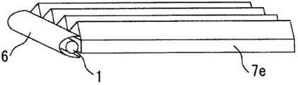
下面,对本实施方式的漫射材料的种类与辉度之间的关系进行说明。在本实施方式中,与实施方式1一样,可使用图2的辉度测量系统测量辉度。但是对于例如像发光体7a~7d那样包含平板状部分的形状,虽可测量霾值,但对于像发光体7e那样没有平板状部分的情况,则无法测量霾值。在这样的情况下,也可以使构成发光体的透明基材及光漫射粒子同样地形成平板状发光体,进行测量。在这里,本实施方式对漫射材料的种类与辉度之间的关系进行探讨。
Next, the relationship between the type of the diffusing material and the luminance of the present embodiment will be described. In this embodiment, as in
辉度(cd/m-2)是注意到以下情况进行测量的。 The luminance (cd/m -2 ) was measured noting the following.
1.在导光板背面配置例如黑布等吸收光线的材料作为吸收片4。这是为了吸收射出至背面侧的光线,而仅测量从正面射出的光线。在这里,以测量辉度的一侧为正面,而与其对置的一侧为背面。
1. Arrange light-absorbing materials such as black cloth on the back of the light guide plate as the absorbing
2.在与入射面对置的端面附近,因来自端面的光的反射影响,有辉度特性发生变化的情况。因此,为了排除该影响,在与入射面对置的端面施以吸收处理5再进行测量。作为吸收处理方法,可以列举例如在与入射面对置的端面涂布黑墨液等的方法。
2. In the vicinity of the end surface facing the incident surface, the luminance characteristics may change due to the influence of reflection of light from the end surface. Therefore, in order to eliminate this influence, the measurement was performed after applying
下面用图5所示的漫射材料的种类或浓度不同的情况下的面发光体的辉度值B(x)与导光距离x(m)之间的关系例,探讨漫射材料的种类与辉度之间的关系。 The following is an example of the relationship between the luminance value B(x) of the surface illuminator and the light guide distance x(m) when the type or concentration of the diffusing material is different as shown in Figure 5, to discuss the types of diffusing materials relationship with brightness. the
图5的关系例是对将漫射材料添加于基材中的面发光体测定其辉度的例子,是将从氧化钛、氧化锌、硫酸钡、氧化铝及聚苯乙烯中选出一种的粒子直径0.5~3μm的漫射材料,以0.02~0.0005重量%的比例添加于厚度5mm的面发光体的例子。任意一个示例均是将导光距离设为0.2m的情况。可知这时因漫射材料的种类或浓度,辉度特性会发生较大的变化。 The relationship example in Fig. 5 is an example of measuring the luminance of a surface light-emitting body with a diffuser added to the base material, and one of titanium oxide, zinc oxide, barium sulfate, aluminum oxide and polystyrene An example in which a diffuser with a particle diameter of 0.5 to 3 μm is added in a proportion of 0.02 to 0.0005% by weight to a surface light emitting body with a thickness of 5 mm. In any of the examples, the light guide distance is set to 0.2m. It can be seen that at this time, the luminance characteristics largely change depending on the type or concentration of the diffusing material. the
本发明人等对漫射材料的种类或浓度不同的发光体进行了种种研究,结果发现以下情况:具有特定范围的折射率差,且添加了特定范围的浓度的发光体,在熄灯时的透明性与亮灯时的辉度的平衡优异。 The inventors of the present invention conducted various studies on illuminants with different types or concentrations of diffusing materials, and found the following: the illuminants with a specific range of refractive index difference and added with a specific range of concentrations have a transparent effect when the light is turned off. It is excellent in balance of brightness at the time of lighting and characteristics. the
折射率差Δn以0.3以上为宜。折射率差Δn比0.3小的情况下,无法高效率取出光线,比起亮灯的亮度透明感差。而0.4以上是理想的。 The refractive index difference Δn is preferably 0.3 or more. When the refractive index difference Δn is smaller than 0.3, the light cannot be extracted efficiently, and the sense of transparency is inferior to the brightness of lighting. However, 0.4 or more is ideal. the
另一方面,当折射率差Δn比3大时,散射光主要是反向散射,也还是比起亮灯时的亮度透明感差。 On the other hand, when the refractive index difference Δn is greater than 3, the scattered light is mainly backscattered, and the sense of transparency is still inferior to the brightness when the light is turned on. the
作为这样的发光体的基材及漫射材料的组合,可在例如丙烯酸类树脂、聚碳酸酯树脂、苯乙烯类树脂等透明树脂中添加氧化钛、氧化锌等光漫射材料微粒。 As a combination of such a base material and a diffusing material of a luminous body, for example, transparent resins such as acrylic resins, polycarbonate resins, and styrenic resins can be added with fine particles of light diffusing materials such as titanium oxide and zinc oxide. the
在本发明的实施方式所使用的漫射粒子的平均直径小的情况下,有被认为是起因于瑞利散射现象的着色等、色调的变化发生。另外,在折射率差Δn小的情况下,也有被认为是起因于瑞利散射现象的着色等、色调的变化发生。具体地说,有在光源附近散射光带有蓝色,而在离开光源的位置则带有黄色的情况。 When the average diameter of the diffusion particles used in the embodiment of the present invention is small, coloring or the like and a change in color tone are thought to be caused by the Rayleigh scattering phenomenon. In addition, when the refractive index difference Δn is small, coloring or the like, which is considered to be caused by the Rayleigh scattering phenomenon, may occur. Specifically, there are cases where the scattered light has a bluish tinge near the light source and a yellow tinge at a position away from the light source. the
因此,为了抑制被认为是起因于瑞利散射现象的着色,以粒子的平均直径(mm)与折射率差绝对值之积为0.0001mm以上为宜。 Therefore, in order to suppress coloring that is believed to be caused by the Rayleigh scattering phenomenon, it is preferable that the product of the average diameter (mm) of the particles and the absolute value of the difference in refractive index be 0.0001 mm or more. the
而且,光漫射粒子的浓度以0.0001重量%以上且0.01重量%以下为宜。随着光漫射粒子的浓度的增高,发光体的透明度降低。因此,为了维持发光体的透明性,例如,如果是板状发光体,则为了维持低霾值,而如果是板状以外的发光体,则为了维持目视 的透明感,需要将光漫射粒子的浓度抑制于较低浓度。另一方面,在光漫射粒子的浓度过低的情况下,无法使光线充分散射,而且发光体的辉度有时会过小。 Furthermore, the concentration of the light-diffusing particles is preferably not less than 0.0001% by weight and not more than 0.01% by weight. As the concentration of light-diffusing particles increases, the transparency of the luminous body decreases. Therefore, in order to maintain the transparency of the illuminant, for example, if it is a plate-shaped illuminant, in order to maintain a low haze value, and if it is a non-plate-shaped illuminant, it is necessary to diffuse the light in order to maintain the visual transparency. The concentration of particles is suppressed at lower concentrations. On the other hand, when the concentration of the light-diffusing particles is too low, the light cannot be sufficiently scattered, and the luminance of the luminous body may be too small. the
其他实施方式 Other implementations
本发明所使用的光源的形状,可以根据入射端面的形状及发光时的外观任意选择,例如除线状外,可采用点状、环状等。 The shape of the light source used in the present invention can be arbitrarily selected according to the shape of the incident end surface and the appearance when emitting light. the
实施例 Example
实施例1 Example 1
以下表示实施例以及比较例。面发光体用射出成型机制作。实施例以及比较例共通的条件如下所示。 Examples and comparative examples are shown below. The surface luminous body is made with an injection molding machine. The conditions common to Examples and Comparative Examples are as follows. the
<共通条件> <common conditions>
基材树脂:PMMA(丙烯酸树脂)(株式会社クラレ制「パラペツト」) Base resin: PMMA (acrylic resin) ("パラピツト" manufactured by Kuraray Co., Ltd.)
折射率:1.494(nD) Refractive index: 1.494(nD)
试样尺寸:厚度5mm×导光长度200mm×宽度70mm Sample size: thickness 5mm×light guide length 200mm×width 70mm
使用光源:日亚化学工业株式会社制「LED NFSW036BT」 Light source used: "LED NFSW036BT" manufactured by Nichia Chemical Industry Co., Ltd.
使用个数:7个 Use number: 7
配置间隔:10mm Configuration interval: 10mm
施加电压:2.8V/1个光源 Applied voltage: 2.8V/1 light source
1个光源的大小:3mm(发光部) Size of 1 light source: 3mm (luminous part)
在表1表示实施例及比较例的材料结构与测量结果。另外,在图10表示辉度衰减系数E(m-1)与每5mm厚度的霾值的关系。横轴的霾值如上所述为每5mm厚度的霾值。从图10所示的测量结果,设霾值(%)为x,辉度衰减系数E(m-1)为y,可导出如下关系式。 Table 1 shows the material structures and measurement results of Examples and Comparative Examples. In addition, FIG. 10 shows the relationship between the luminance attenuation coefficient E(m −1 ) and the haze value per 5 mm thickness. The haze value on the horizontal axis is the haze value per 5 mm thickness as described above. From the measurement results shown in FIG. 10 , assuming that the haze value (%) is x, and the luminance attenuation coefficient E(m −1 ) is y, the following relationship can be derived.
氧化钛 y=1.4797x Titanium oxide y=1.4797x
氧化锌 y=0.7726x Zinc oxide y=0.7726x
氧化铝 y=0.3662x Aluminum oxide y=0.3662x
苯乙烯 y=0.1444x Styrene y=0.1444x
在该关系式中,x的系数相当于计算值(m-1/%)。 In this relational expression, the coefficient of x corresponds to the calculated value (m -1 /%).
另外,在图10中,以二条虚线表示计算值为0.55(m-1/%)以上、10.0(m-1/%)以下的范围。右侧虚线为y=0.55x的关系式,左侧虚线为y=10.0x的关系式。 In addition, in FIG. 10 , the range in which the calculated value is not less than 0.55 (m −1 /%) and not more than 10.0 (m −1 /%) is indicated by two dotted lines. The dotted line on the right is the relational expression of y=0.55x, and the dotted line on the left is the relational expression of y=10.0x.
在实施例1及实施例2中,计算值为约0.77~约1.48(m-1/%),霾值为1~8.6%。 In Example 1 and Example 2, the calculated value is about 0.77 to about 1.48 (m −1 /%), and the haze value is 1 to 8.6%.
在比较例1及比较例2中,计算值为约0.14~约0.37(m-1/%),霾值为3~25.3%。 In Comparative Example 1 and Comparative Example 2, the calculated value was about 0.14 to about 0.37 (m −1 /%), and the haze value was 3 to 25.3%.
另外,从表1的结果可知,为了使霾值为30%以下,以使S1的值为0.15以下为宜。
In addition, from the results in Table 1, it can be seen that the value of S1 is preferably 0.15 or less in order to make the
表1实施例及比较例与其结构 Table 1 embodiment and comparative example and structure thereof
[表1] [Table 1]

对这些实施例及比较例的面发光体,利用目视评价分5级评价熄灯时的透明感及亮灯时的亮度。最佳情况为5,最差情况为1,在本评价中,以3以上为良好。其结果汇总于表2。如表2所示,实施例的面发光体其透明感佳且亮。另一方面,比较例的面发光体其透明感差或暗。 For the surface light-emitting bodies of these Examples and Comparative Examples, the transparency when the light was off and the brightness when the light was on were evaluated by visual evaluation on a five-point scale. The best case is 5, the worst case is 1, and in this evaluation, 3 or more is considered good. The results are summarized in Table 2. As shown in Table 2, the surface light-emitting body of the embodiment has a good sense of transparency and is bright. On the other hand, the surface light-emitting body of the comparative example was poor in transparency or dark. the
表2实施例及比较例的评价结果 The evaluation result of table 2 embodiment and comparative example
[表2] [Table 2]

实施例2 Example 2
设试样尺寸为直径10mm、长度200mm的圆柱状,制成使用光源的个数为一个的实施例3、4及比较例3、4。实施例3、4的漫射材料分别与实施例1、2相同,比较例3、4的漫射材料分别与比较例1、2相同。 The sample size was a cylinder with a diameter of 10 mm and a length of 200 mm, and Examples 3 and 4 and Comparative Examples 3 and 4 using one light source were produced. The diffusing materials of Examples 3 and 4 are the same as those of Examples 1 and 2, respectively, and the diffusing materials of Comparative Examples 3 and 4 are the same as those of Comparative Examples 1 and 2, respectively. the
对这些实施例3、4及比较例3、4的棒状发光体,利用目视方法评价熄灯时的透明感及亮灯时的亮度。其结果表明,实施例的发光体其透明感佳且亮。另一方面,比较例的发光体其透明感 差或暗。 With regard to the rod-shaped light emitting bodies of these Examples 3 and 4 and Comparative Examples 3 and 4, the transparency at the time of turning off the light and the brightness at the time of turning on the light were evaluated visually. The results show that the luminous body of the embodiment has a good sense of transparency and is bright. On the other hand, the illuminant of the comparative example had a poor or dark sense of transparency. the
如上所示,如果采用本发明的导光方式的面发光体,则可实现熄灯时透明感好且亮灯时明亮、能作为背光灯或遮光板发挥作用的显示装置。可实现例如娱乐用装饰。 As described above, according to the light-guiding surface light emitting body of the present invention, it is possible to realize a display device that has a good sense of transparency when the light is off, is bright when the light is on, and can function as a backlight or a visor. Decoration for entertainment can be realized, for example. the
另外,本发明不限定于上述实施方式,只要是在未超出本发明的实质范围,即可适当变更。 In addition, this invention is not limited to the said embodiment, As long as it does not deviate from the essential range of this invention, it can change suitably. the
本申请案主张以2009年3月31日提出申请的日本专利申请特愿2009-084118、以及2009年7月6日提出申请的日本专利申请特愿2009-159444作为基础的优先权,其中所有内容均揭示于本说明书中。 This application claims priority based on Japanese Patent Application No. 2009-084118 filed on March 31, 2009, and Japanese Patent Application No. 2009-159444 filed on July 6, 2009, all of which are disclosed in this specification. the
Claims (10)
Applications Claiming Priority (5)
| Application Number | Priority Date | Filing Date | Title |
|---|---|---|---|
| JP2009084118 | 2009-03-31 | ||
| JP2009-084118 | 2009-03-31 | ||
| JP2009159444 | 2009-07-06 | ||
| JP2009-159444 | 2009-07-06 | ||
| PCT/JP2010/002047 WO2010113422A1 (en) | 2009-03-31 | 2010-03-24 | Illuminant |
Publications (2)
| Publication Number | Publication Date |
|---|---|
| CN102428315A CN102428315A (en) | 2012-04-25 |
| CN102428315B true CN102428315B (en) | 2014-01-29 |
Family
ID=42827738
Family Applications (1)
| Application Number | Title | Priority Date | Filing Date |
|---|---|---|---|
| CN201080022364.XA Expired - Fee Related CN102428315B (en) | 2009-03-31 | 2010-03-24 | Light Emitter |
Country Status (6)
| Country | Link |
|---|---|
| US (1) | US8746949B2 (en) |
| JP (1) | JP5297522B2 (en) |
| KR (2) | KR20120022834A (en) |
| CN (1) | CN102428315B (en) |
| TW (1) | TWI504838B (en) |
| WO (1) | WO2010113422A1 (en) |
Families Citing this family (33)
| Publication number | Priority date | Publication date | Assignee | Title |
|---|---|---|---|---|
| JP5356301B2 (en) * | 2010-03-30 | 2013-12-04 | 株式会社クラレ | Surface light emitter and front light device |
| JP5714887B2 (en) * | 2010-12-22 | 2015-05-07 | 株式会社クラレ | Backlight |
| US9507072B2 (en) * | 2012-10-26 | 2016-11-29 | Mitsubishi Rayon Co., Ltd. | Light guide, manufacturing method of light guide, optical shutter, and planar light-source device |
| ITTO20120988A1 (en) * | 2012-11-14 | 2014-05-15 | Light In Light S R L | ARTIFICIAL LIGHTING SYSTEM TO SIMULATE A NATURAL LIGHTING |
| US9291320B2 (en) | 2013-01-30 | 2016-03-22 | Cree, Inc. | Consolidated troffer |
| US9625638B2 (en) | 2013-03-15 | 2017-04-18 | Cree, Inc. | Optical waveguide body |
| US9366396B2 (en) | 2013-01-30 | 2016-06-14 | Cree, Inc. | Optical waveguide and lamp including same |
| US9690029B2 (en) | 2013-01-30 | 2017-06-27 | Cree, Inc. | Optical waveguides and luminaires incorporating same |
| US9442243B2 (en) | 2013-01-30 | 2016-09-13 | Cree, Inc. | Waveguide bodies including redirection features and methods of producing same |
| US9869432B2 (en) | 2013-01-30 | 2018-01-16 | Cree, Inc. | Luminaires using waveguide bodies and optical elements |
| US10436969B2 (en) | 2013-01-30 | 2019-10-08 | Ideal Industries Lighting Llc | Optical waveguide and luminaire incorporating same |
| US10379278B2 (en) * | 2013-03-15 | 2019-08-13 | Ideal Industries Lighting Llc | Outdoor and/or enclosed structure LED luminaire outdoor and/or enclosed structure LED luminaire having outward illumination |
| US10400984B2 (en) | 2013-03-15 | 2019-09-03 | Cree, Inc. | LED light fixture and unitary optic member therefor |
| US9798072B2 (en) | 2013-03-15 | 2017-10-24 | Cree, Inc. | Optical element and method of forming an optical element |
| US9920901B2 (en) | 2013-03-15 | 2018-03-20 | Cree, Inc. | LED lensing arrangement |
| US9366799B2 (en) | 2013-03-15 | 2016-06-14 | Cree, Inc. | Optical waveguide bodies and luminaires utilizing same |
| US10502899B2 (en) * | 2013-03-15 | 2019-12-10 | Ideal Industries Lighting Llc | Outdoor and/or enclosed structure LED luminaire |
| US9645303B2 (en) | 2013-03-15 | 2017-05-09 | Cree, Inc. | Luminaires utilizing edge coupling |
| US10436970B2 (en) | 2013-03-15 | 2019-10-08 | Ideal Industries Lighting Llc | Shaped optical waveguide bodies |
| US10209429B2 (en) | 2013-03-15 | 2019-02-19 | Cree, Inc. | Luminaire with selectable luminous intensity pattern |
| US12372219B2 (en) * | 2014-05-30 | 2025-07-29 | Cree Lighting Usa Llc | LED luminaire with a cavity, finned interior, and a curved outer wall extending from a surface on which the light source is mounted |
| US11719882B2 (en) | 2016-05-06 | 2023-08-08 | Ideal Industries Lighting Llc | Waveguide-based light sources with dynamic beam shaping |
| US10416377B2 (en) | 2016-05-06 | 2019-09-17 | Cree, Inc. | Luminaire with controllable light emission |
| US10183120B2 (en) * | 2016-07-15 | 2019-01-22 | Common Sensing Inc. | Dose measurement systems and methods |
| JP7184793B2 (en) * | 2017-10-30 | 2022-12-06 | 株式会社クラレ | Methacrylic resin, methacrylic resin composition and molded article |
| EP3763994A4 (en) | 2018-03-07 | 2021-04-21 | Mitsubishi Chemical Corporation | TRANSPARENT RESIN COMPOSITION, MOLDED RESIN BODY, LAMP PROTECTOR, VEHICLE LAMP PROTECTOR, COMBINATION LAMP PROTECTORS, AND VEHICLE |
| US10739513B2 (en) | 2018-08-31 | 2020-08-11 | RAB Lighting Inc. | Apparatuses and methods for efficiently directing light toward and away from a mounting surface |
| US10801679B2 (en) | 2018-10-08 | 2020-10-13 | RAB Lighting Inc. | Apparatuses and methods for assembling luminaires |
| JP7262577B2 (en) | 2019-05-27 | 2023-04-21 | 三菱電機株式会社 | Diffuser and Lighting Device |
| JP7470123B2 (en) * | 2019-07-30 | 2024-04-17 | 三菱エンジニアリングプラスチックス株式会社 | Thermoplastic resin composition and molded article |
| EP4045846A4 (en) * | 2019-10-15 | 2023-07-19 | LEIA Inc. | PRIVACY MODE BACKLIGHT, PRIVACY DISPLAY UNIT, AND METHOD |
| CN115151753A (en) * | 2020-02-27 | 2022-10-04 | 昕诺飞控股有限公司 | light generating device |
| EP4136490A1 (en) * | 2020-04-15 | 2023-02-22 | CommScope Connectivity Belgium BV | Device and method for sealing cables in telecommunications enclosures |
Citations (2)
| Publication number | Priority date | Publication date | Assignee | Title |
|---|---|---|---|---|
| JP2006286217A (en) * | 2005-03-31 | 2006-10-19 | Nippon Zeon Co Ltd | Backlight device |
| CN101258440A (en) * | 2005-09-06 | 2008-09-03 | 可乐丽股份有限公司 | Light-diffusing methacrylic resin light guide body and surface light source device including the light guide body |
Family Cites Families (9)
| Publication number | Priority date | Publication date | Assignee | Title |
|---|---|---|---|---|
| JPS57128383A (en) | 1981-02-02 | 1982-08-09 | Mitsubishi Electric Corp | Surface lighting apparatus |
| JPH0776080B2 (en) | 1989-11-21 | 1995-08-16 | 大和ハウス工業株式会社 | Aerial work vehicle |
| WO1994012898A1 (en) | 1992-11-27 | 1994-06-09 | Yasuhiro Koike | Apparatus for guiding diffused light |
| JP3773129B2 (en) * | 1996-07-16 | 2006-05-10 | 三菱レイヨン株式会社 | Light guide for surface light source element and surface light source element |
| JP2006294343A (en) * | 2005-04-07 | 2006-10-26 | Mitsubishi Rayon Co Ltd | LED surface light source device |
| US8456590B2 (en) * | 2007-01-09 | 2013-06-04 | Dai Nippon Printing Co., Ltd. | Optical sheet, surface light source and display device |
| JP2008216879A (en) | 2007-03-07 | 2008-09-18 | Sumitomo Chemical Co Ltd | White surface light source device and liquid crystal display device |
| KR101024235B1 (en) * | 2007-04-25 | 2011-03-29 | 스미또모 가가꾸 가부시끼가이샤 | Light diffuser |
| US20120051696A2 (en) * | 2010-04-08 | 2012-03-01 | Evonik Roehm Gmbh | Light guide body having high luminous intensity and high transparency |
-
2010
- 2010-03-24 CN CN201080022364.XA patent/CN102428315B/en not_active Expired - Fee Related
- 2010-03-24 US US13/257,656 patent/US8746949B2/en not_active Expired - Fee Related
- 2010-03-24 WO PCT/JP2010/002047 patent/WO2010113422A1/en not_active Ceased
- 2010-03-24 KR KR1020117025646A patent/KR20120022834A/en not_active Ceased
- 2010-03-24 KR KR1020177006899A patent/KR101749480B1/en not_active Expired - Fee Related
- 2010-03-24 JP JP2011506994A patent/JP5297522B2/en not_active Expired - Fee Related
- 2010-03-30 TW TW099109492A patent/TWI504838B/en not_active IP Right Cessation
Patent Citations (2)
| Publication number | Priority date | Publication date | Assignee | Title |
|---|---|---|---|---|
| JP2006286217A (en) * | 2005-03-31 | 2006-10-19 | Nippon Zeon Co Ltd | Backlight device |
| CN101258440A (en) * | 2005-09-06 | 2008-09-03 | 可乐丽股份有限公司 | Light-diffusing methacrylic resin light guide body and surface light source device including the light guide body |
Also Published As
| Publication number | Publication date |
|---|---|
| US8746949B2 (en) | 2014-06-10 |
| JP5297522B2 (en) | 2013-09-25 |
| TWI504838B (en) | 2015-10-21 |
| KR20120022834A (en) | 2012-03-12 |
| TW201043871A (en) | 2010-12-16 |
| KR101749480B1 (en) | 2017-06-20 |
| CN102428315A (en) | 2012-04-25 |
| KR20170032484A (en) | 2017-03-22 |
| JPWO2010113422A1 (en) | 2012-10-04 |
| US20120008338A1 (en) | 2012-01-12 |
| WO2010113422A1 (en) | 2010-10-07 |
Similar Documents
| Publication | Publication Date | Title |
|---|---|---|
| CN102428315B (en) | Light Emitter | |
| CN102411165B (en) | Light guide device, backlight module and liquid crystal display with the light guide device | |
| JP2007304553A (en) | Prism sheet, backlight unit including the prism sheet, and liquid crystal display device | |
| CN101836037A (en) | Surface light source | |
| JP4933512B2 (en) | Light guide plate | |
| JP5089960B2 (en) | Surface light source device, backlight unit including the same, and liquid crystal display device including the backlight unit | |
| KR101692888B1 (en) | Light guiding panel and back light unit using the same | |
| JP5323469B2 (en) | LIGHTING DEVICE AND LIGHT MANUFACTURING METHOD FOR LIGHTING DEVICE | |
| KR20170134617A (en) | Texture gradient for uniform light output from transparent backlight | |
| JP2000113708A (en) | Lighting system | |
| JP2001305540A (en) | Reflective liquid crystal display | |
| JP2004029648A (en) | Light diffusing sheet | |
| JP7476739B2 (en) | Illumination body and illumination body with light source | |
| JP5714887B2 (en) | Backlight | |
| JP2011191339A (en) | Transflective liquid crystal display device | |
| JP2016089534A (en) | Partition panel and partition system | |
| JP5442533B2 (en) | Luminous body | |
| JP2013140703A (en) | Emission light diffusion layer and light guide device using the same | |
| WO2018235803A1 (en) | Daylighting member and daylighting device | |
| JP3549491B2 (en) | Light diffusion sheet and backlight unit using the same | |
| KR20120077242A (en) | Optical film enhanced brightness and diffusion | |
| JP2001076522A (en) | Light source device | |
| JP5356301B2 (en) | Surface light emitter and front light device | |
| JP2010140704A (en) | Light guide plate, and method of manufacturing light guide plate | |
| RU124972U1 (en) | LIGHT PANEL |
Legal Events
| Date | Code | Title | Description |
|---|---|---|---|
| C06 | Publication | ||
| PB01 | Publication | ||
| C10 | Entry into substantive examination | ||
| SE01 | Entry into force of request for substantive examination | ||
| C14 | Grant of patent or utility model | ||
| GR01 | Patent grant | ||
| CF01 | Termination of patent right due to non-payment of annual fee | ||
| CF01 | Termination of patent right due to non-payment of annual fee |
Granted publication date: 20140129 Termination date: 20210324 |