CN102428252A - In situ method and system for extraction of oil from shale - Google Patents
In situ method and system for extraction of oil from shale Download PDFInfo
- Publication number
- CN102428252A CN102428252A CN2010800211962A CN201080021196A CN102428252A CN 102428252 A CN102428252 A CN 102428252A CN 2010800211962 A CN2010800211962 A CN 2010800211962A CN 201080021196 A CN201080021196 A CN 201080021196A CN 102428252 A CN102428252 A CN 102428252A
- Authority
- CN
- China
- Prior art keywords
- retort
- oil
- oil shale
- well
- vapor
- Prior art date
- Legal status (The legal status is an assumption and is not a legal conclusion. Google has not performed a legal analysis and makes no representation as to the accuracy of the status listed.)
- Granted
Links
Images


Classifications
-
- E—FIXED CONSTRUCTIONS
- E21—EARTH OR ROCK DRILLING; MINING
- E21B—EARTH OR ROCK DRILLING; OBTAINING OIL, GAS, WATER, SOLUBLE OR MELTABLE MATERIALS OR A SLURRY OF MINERALS FROM WELLS
- E21B43/00—Methods or apparatus for obtaining oil, gas, water, soluble or meltable materials or a slurry of minerals from wells
- E21B43/16—Enhanced recovery methods for obtaining hydrocarbons
- E21B43/24—Enhanced recovery methods for obtaining hydrocarbons using heat, e.g. steam injection
-
- E—FIXED CONSTRUCTIONS
- E21—EARTH OR ROCK DRILLING; MINING
- E21B—EARTH OR ROCK DRILLING; OBTAINING OIL, GAS, WATER, SOLUBLE OR MELTABLE MATERIALS OR A SLURRY OF MINERALS FROM WELLS
- E21B43/00—Methods or apparatus for obtaining oil, gas, water, soluble or meltable materials or a slurry of minerals from wells
- E21B43/30—Specific pattern of wells, e.g. optimising the spacing of wells
Landscapes
- Life Sciences & Earth Sciences (AREA)
- Engineering & Computer Science (AREA)
- Geology (AREA)
- Mining & Mineral Resources (AREA)
- Physics & Mathematics (AREA)
- Environmental & Geological Engineering (AREA)
- Fluid Mechanics (AREA)
- General Life Sciences & Earth Sciences (AREA)
- Geochemistry & Mineralogy (AREA)
- Production Of Liquid Hydrocarbon Mixture For Refining Petroleum (AREA)
- Organic Low-Molecular-Weight Compounds And Preparation Thereof (AREA)
Abstract
Description
相关申请的交叉引用Cross References to Related Applications
本申请是2007年1月19提交的、第11/655,152号美国申请的部分继续申请,所述美国申请要求2006年1月20日提交的美国临时申请60/760,698的优先权,所述美国临时申请所披露的内容以引用的方式被全文结合到这里。本申请也主张2009年5月15日提交的、序列号为61/178,856的美国临时申请和2010年4月27日提交的、序列号为61/328,519的美国临时申请的优先权,上述美国临时申请所披露的内容以引用的方式被全文结合到这里。This application is a continuation-in-part of U.S. Application Serial No. 11/655,152, filed January 19, 2007, which claims priority to U.S.
背景技术 Background technique
在美国和世界各地都已经发现了大的地下油页岩沉积物。与石油沉积物相比,这些油页岩沉积物的特征在于它们的固体状态;其中有机材料是通常被称作“油母岩质”的、与无机矿物成分密切地混合的聚合物类结构。将油页岩沉积物加热到在大约300C以上的温度并持续几天到几个星期已经显示,将导致固态油母岩质高温分解以形成石油类“页岩油”和天然气类气态产品。部分地,由于难以有效地加热地下油页岩沉积物,阻碍了经济地从油页岩提取产品。Large underground deposits of oil shale have been discovered in the United States and around the world. In contrast to petroleum deposits, these oil shale deposits are characterized by their solid state; in which the organic material is a polymer-like structure, often referred to as "kerogen", intimately mixed with inorganic mineral components. Heating oil shale deposits to temperatures above about 300C for days to weeks has been shown to result in the pyrolysis of solid kerogen to form petroleum-like "shale oil" and natural gas-like gaseous products. Economical extraction of products from oil shale has been hampered, in part, by the difficulty of efficiently heating subterranean oil shale deposits.
因此,在本领域中有对于能有效地原位加热大体积的油页岩沉积物的方法和设备的需求。Accordingly, there is a need in the art for methods and apparatus capable of efficiently heating large volumes of oil shale deposits in situ.
发明内容 Contents of the invention
这里所披露的系统和方法包括如下的几个目的、好处和/或特征:The systems and methods disclosed herein include several objects, benefits and/or features as follows:
干馏操作的方式使得干馏物的出口与活跃的干馏区域距离足够远,通过在重力驱动流下返回到油池的油的凝结维持油池的水平。The retort is operated in such a way that the outlet of the retort is sufficiently far from the active retort zone that the level of the sump is maintained by condensation of the oil returning to the sump under gravity driven flow.
干馏操作的方式使得干馏物的压力水平维持成足以在干馏物内凝结油蒸气并且在重力驱动流下返回以维持沸腾油池的水平。The retort is operated in such a way that the pressure level of the retort is maintained at a level sufficient to condense oil vapor within the retort and return under gravity driven flow to maintain a boiling oil pool.
干馏操作的方式使得从地面返回液态油从而维持沸腾油池的水平。Retort operates in such a way that liquid oil is returned from the surface to maintain the level of the boiling oil pool.
干馏操作的方式使得以正确的沸腾点分布的液态油用来维持油池中的适当的沸腾分布从而优化从沸腾油池到干馏物的热传递。The retort operates in such a way that the liquid oil with the correct boiling point distribution is used to maintain the proper boiling distribution in the oil sump to optimize heat transfer from the boiling oil sump to the retort.
干馏操作的方式使得从地面返回的油冷却从干馏物出来的气体和蒸气并且使额外的油凝结并通过重力驱动流返回到沸腾油池。The retort operates in such a way that the oil returning from the surface cools the gases and vapors coming out of the retort and allows the extra oil to condense and return by gravity driven flow to the boiling oil pool.
干馏操作的方式使得来自地面的油的返回、返回油和排出蒸气之间的逆流热交换以及干馏物中的压力的组合用来维持沸腾油池中的适当的水平和成分。The retort operates in such a way that a combination of return of oil from the surface, countercurrent heat exchange between the return oil and vented vapor, and pressure in the retort is used to maintain the proper level and composition in the boiling oil pool.
竖直蛛网井用来分布厚油页岩资源内的沸腾油的结构。Vertical spider wells are structures used to distribute boiling oil within thick oil shale resources.
加热器包含在倾斜井眼中以有助于将油排到沸腾油池中的结构。A heater is included in the deviated wellbore to help drain the oil into the boiling oil pool.
本发明涉及用于从位于覆盖层下面的油页岩沉积物内的地下油页岩本体提取烃的系统和方法。所述系统包括加热油页岩本体的能量递送子系统和用于收集从油页岩本体干馏的烃的烃收集子系统。The present invention relates to systems and methods for extracting hydrocarbons from subterranean oil shale bodies within oil shale deposits underlying overburdens. The system includes an energy delivery subsystem for heating the oil shale body and a hydrocarbon collection subsystem for collecting hydrocarbons retorted from the oil shale body.
所述能量递送子系统包括至少一个从地球的表面钻过覆盖层到达邻近油页岩本体的底部的深度的能量递送井,所述能量递送井大体上从待干馏的油页岩本体的近端之上的表面位置向下延伸并且继续延伸到邻近油页岩本体的底部。所述能量递送井可以倾斜地延伸到油页岩本体中。The energy delivery subsystem includes at least one energy delivery well drilled from the surface of the earth through the overburden to a depth adjacent the bottom of the oil shale body, the energy delivery well extending from substantially the proximal end of the oil shale body to be retorted The upper surface location extends downward and continues to the bottom adjacent to the oil shale body. The energy delivery wells may extend obliquely into the oil shale body.
所述能量递送井包括热递送装置,所述热递送装置部分在被干馏的油页岩本体之下延伸并且横过被干馏的油页岩本体延伸,从它的近端延伸到它的远端。所述热递送装置适于将处于至少等于干馏温度的温度的热能递送到待干馏的油页岩本体。The energy delivery well includes a heat delivery device extending partially below and across the retorted oil shale body from its proximal end to its distal end . The heat delivery device is adapted to deliver thermal energy to the body of oil shale to be retorted at a temperature at least equal to the retort temperature.
所述热递送装置包括沿着油页岩本体的底部延伸的流体传送管。所述流体传送管适于接收被加热到至少干馏温度的加热流体并且适于将热能从加热流体递送到油页岩本体。在一个实施方式中,在所述系统的操作的第一阶段,所述流体传送管接收和传送第一加热流体,并且在所述系统的操作的第二阶段接,所述流体传送管接收和传递第二加热流体。所述流体可以是相同的或不同的。例如,流体可以是蒸汽或者高温介质。The heat delivery means includes a fluid delivery tube extending along the bottom of the oil shale body. The fluid delivery tube is adapted to receive a heating fluid heated to at least a retort temperature and to deliver thermal energy from the heating fluid to the oil shale body. In one embodiment, during a first phase of operation of said system, said fluid delivery tube receives and delivers a first heating fluid, and during a second phase of operation of said system, said fluid delivery tube receives and A second heating fluid is delivered. The fluids may be the same or different. For example, the fluid may be steam or a high temperature medium.
所述系统可以进一步包括至少一个钻过待干馏的油页岩本体的蒸气管道。所述蒸气管道具有位于接近待干馏的油页岩本体的底部的下端。所述蒸气管道适于依靠热递送子系统通过油页岩本体向上传送从油页岩干馏的蒸气。所述蒸气管道也可以允许所述蒸气在所述蒸气管道和接近所述蒸气管道的油页岩本体之间穿过。当所述蒸气上升通过油页岩时,所述蒸汽管道也允许所述蒸气将热能提供到所述油页岩,所述热能至少部分由回流提供。The system may further include at least one vapor conduit drilled through the body of oil shale to be retorted. The vapor conduit has a lower end located near the bottom of the body of oil shale to be retorted. The vapor conduit is adapted to transport vapor retorted from the oil shale up through the body of the oil shale by means of a heat delivery subsystem. The vapor conduit may also allow passage of the vapor between the vapor conduit and a body of oil shale proximate to the vapor conduit. The steam conduit also allows the steam to provide thermal energy to the oil shale as the steam rises through the oil shale, the thermal energy being at least partially provided by return flow.
所述蒸气管道至少部分是开口孔和被填塞的砾石,成为所述蒸气管道提供完整性和允许干馏蒸气和液体运动的渗透性。所述蒸气管道至少部分是带有外罩,所述外罩是穿孔的以允许干馏蒸气和液体在所述蒸气管道和待干馏的油页岩本体之间穿过。所述蒸气管道可以呈现蛛网井的形式。The vapor conduit is at least partially open cell and packed with gravel providing integrity and permeability to the vapor conduit to allow movement of retort vapor and liquid. The vapor conduit is at least partially shrouded, the casing being perforated to allow passage of retort vapor and liquid between the vapor conduit and the body of oil shale to be retorted. The vapor conduit may take the form of a spider well.
所述烃收集子系统包括至少一个带外罩的井,所述至少一个带外罩的井钻到地球中通过覆盖层并且通过待干馏的油页岩本体。所述带外罩的井具有位于地球表面处的上端,所述带外罩的井延伸通过所述覆盖层至少到达所述覆盖层的底部。所述烃收集子系统也包括生产管,所述生产管具有在所述带外罩的井的所述上端处的集采端并且具有位于待干馏的油页岩本体的底部处的收集端,所述生产管适于通过其传送液态烃。The hydrocarbon collection subsystem includes at least one shrouded well drilled into the earth through the overburden and through the body of oil shale to be retorted. The shrouded well has an upper end at the earth's surface, the shrouded well extending through the overburden at least to the bottom of the overburden. The hydrocarbon collection subsystem also includes a production tubing having a gathering end at the upper end of the shrouded well and having a collecting end at the bottom of the body of oil shale to be retorted, the The production tubing is adapted to convey liquid hydrocarbons therethrough.
池槽位于所述收集端下面并且与所述收集端连通。所述池槽适于集采从油页岩沉积物干馏的凝结液态烃,并且适于允许液态烃被从所述池槽泵送到所述生产管的所述收集端中。A sump is located below the collection end and communicates with the collection end. The sump is adapted to gather condensed liquid hydrocarbons retorted from oil shale deposits and to allow liquid hydrocarbons to be pumped from the sump into the collection end of the production tubing.
也可以预期得到用于干馏和提取地下烃的方法。所述方法包括钻一能量递送井,所述能量递送井从地面延伸到接近烃的底部的位置。从底部加热烃,以形成干馏物,所述干馏物沿着所述能量递送井的一部分延伸。将蒸气管延伸到接近所述干馏物的位置,所述蒸气管具有相应于沿着所述能量递送井的最接近地面出口的干馏物区域的入口。Methods for retorting and extracting subterranean hydrocarbons are also contemplated. The method includes drilling an energy delivery well extending from the surface to a location near the bottom of the hydrocarbon. Hydrocarbons are heated from the bottom to form a retort that extends along a portion of the energy delivery well. Extending a vapor tube proximate to the retort, the vapor tube having an inlet corresponding to a region of the retort along the energy delivery well closest to a surface outlet.
在第一阶段,所述方法包括将进入所述入口的蒸气的温度维持在大约等于未加热的周围烃的温度。所述方法包括第二阶段,所述第二阶段包括进一步加热所述干馏物直到进入所述入口的所述蒸气在大约150到1100psig之间的压力下达到大约180到290摄氏度之间的温度。第三阶段包括进一步将所述干馏物加热到大约325和350摄氏度之间。In a first stage, the method includes maintaining the temperature of the vapor entering the inlet approximately equal to the temperature of unheated surrounding hydrocarbons. The method includes a second stage comprising further heating the retort until the vapor entering the inlet reaches a temperature of between about 180 and 290 degrees Celsius at a pressure of between about 150 and 1100 psig. The third stage involves further heating the retort to between about 325 and 350 degrees Celsius.
所述方法优选为包括将加热器设置在所述能量递送井中,并且可以包括作为时间的函数地将蒸气管的入口移动的远离所述加热器。所述方法可以包括将油再循环到干馏物中。可以将油从干馏物移动到地面,并且根据需要将油从地面再循环到所述干馏物中,并且从干馏物去除掉多余的水。The method preferably includes positioning a heater in the energy delivery well, and may include moving the inlet of the vapor tube away from the heater as a function of time. The method may include recycling the oil to the retort. Oil may be moved from the retort to the surface, and recycled from the surface to the retort as needed, with excess water removed from the retort.
在另一实施方式中,用于从油页岩层干馏和提取地下烃的方法包括钻一从位于地面处的近端延伸到倾斜地延伸到所述层中的远端的井。将加热器设置在所述井的远端附近并且设置在所述层内。沿着所述井延伸管道并且通过将所述层加热到超过82摄氏度,而破碎所述层。通过所述管道去除掉通过加热所述层产生的油和气体,而形成用于连续破碎的空隙度。In another embodiment, a method for retorting and extracting subterranean hydrocarbons from an oil shale formation includes drilling a well extending from a proximal end at the surface to a distal end extending obliquely into the formation. A heater is positioned near the distal end of the well and within the layer. Pipelines are run along the well and the layer is broken up by heating the layer to over 82 degrees Celsius. Oil and gas generated by heating the layer are removed through the conduits to create voids for continuous crushing.
附图说明 Description of drawings
图1是适合利用热机械破碎的CCRTM方法的一实施方式的示意性的示图;Figure 1 is a schematic representation of one embodiment of the CCR ™ process suitable for utilizing thermomechanical fragmentation;
图2是在伊利石开采区间中执行的CCRTM方法的一实施方式的示意性的示图;Figure 2 is a schematic illustration of an embodiment of the CCR ™ method implemented in an illite mining interval;
图3是使用伊利石开采区间中的平行的热井和生产井的一些优化构造的商业操作的代表性的概念布置图;Figure 3 is a representative conceptual layout of a commercial operation using some optimized configurations of parallel thermal and production wells in an illite mining interval;
图4是CCRTM方法的代表性的实施方式的示意性的视图;Figure 4 is a schematic view of a representative embodiment of the CCR ™ method;
图5示出了在两个选择的时间,两个井之间的油母岩质变换轮廓,假如没有井眼破碎;Figure 5 shows the kerogen transformation profile between the two wells at two selected times, assuming no borehole fracture;
图6示出了当应力随着温度增加并且强度随着温度降低时发生的热机械破碎;Figure 6 shows thermomechanical fracture that occurs when stress increases with temperature and strength decreases with temperature;
图7示出了来自加热井的热机械破碎波的传播;Figure 7 shows the propagation of a thermomechanical breaking wave from a heater well;
图8示出通过热机械破碎形成的大油页岩干馏洞;Figure 8 shows a large oil shale retort tunnel formed by thermomechanical fragmentation;
图9示出使用来自表面的再循环以及干馏物内的回流的通常CCRTM方法;Figure 9 shows a typical CCR ™ process using recycle from the surface and reflux within the retort;
图10图示了CCRTM干馏的基于蒸气生产井管道的入口温度的三个阶段;Figure 10 illustrates the three stages of CCR ™ retort based on the inlet temperature of the steam production well tubing;
图11示出了在R-1区域的地层中的倾斜的加热器-生产井的放置;Figure 11 shows the placement of inclined heater-production wells in the formation of the R-1 zone;
图12是示出了再循环的油的量取决于生产井管道的入口处的温度的示图;Figure 12 is a graph showing the amount of oil recirculated as a function of the temperature at the inlet of the production well tubing;
图13是代表性的井实施方式的示意性的示图;Figure 13 is a schematic illustration of a representative well embodiment;
图14是用于图13中所示的代表性的井实施方式的位置图;Figure 14 is a location diagram for the representative well embodiment shown in Figure 13;
图15是井区域的放大图,其中标识了关键的方法部件;Figure 15 is an enlarged view of the well area with key method components identified;
图16示出了围绕被加热区域的断层分析井的可能位置的代表性的布置图;Figure 16 shows a representative layout of possible locations of tomography wells around the heated region;
图17示出了整体在干馏物内的加热器和井;Figure 17 shows the heater and well integrated within the retort;
图18是加热器电连接系统的概念设计;Figure 18 is a conceptual design of the heater electrical connection system;
图19示出了电加热器的三组三个加热器元件;Figure 19 shows three sets of three heater elements for an electric heater;
图20是在封隔器和电缆过渡之上的代表性的生产管道构造;Figure 20 is a representative production tubing configuration above the packer and cable transition;
图21是油-水-气馏分系统的透视图;Figure 21 is a perspective view of an oil-water-gas fractionation system;
图22是另一代表性的井实施方式的示意性的视图;Figure 22 is a schematic view of another representative well embodiment;
图23是图22中所示的代表性的井实施方式的位置图;Figure 23 is a location diagram of the representative well embodiment shown in Figure 22;
图24是图23中所示的井区域的放大图,其中标识了关键方法部件;Figure 24 is an enlarged view of the well area shown in Figure 23 with key method components identified;
图25示出了图22中所示的断层分析井的可能位置的代表性的布置图;Figure 25 shows a representative layout of possible locations for the fault analysis wells shown in Figure 22;
图26是包括倾斜加热器井和竖直生产井的干馏生产井的另一实施方式的示意性的描述;Figure 26 is a schematic depiction of another embodiment of a retort production well comprising an inclined heater well and a vertical production well;
图27是图26中所示的加热器组件的概念示图;Figure 27 is a conceptual diagram of the heater assembly shown in Figure 26;
图28是图26和27中所示的干馏生产井构造的详细的示意性的示图;Figure 28 is a detailed schematic illustration of the retort production well configuration shown in Figures 26 and 27;
图29是用于实现CCR干馏的井构造的另一代表性的实施方式的示意性示图;和29 is a schematic illustration of another representative embodiment of a well configuration for effecting CCR retorts; and
图30是用于实现包括热传递对流环的CCR干馏的井构造的再另一代表性的实施方式的示意性的示图。30 is a schematic illustration of yet another representative embodiment of a well configuration for implementing CCR retorts including heat transfer convective rings.
具体实施方式 Detailed ways
本发明涉及页岩油的原位加热和提取,并且尤其涉及传导、对流、回流(Conduction,Convection,Reflux)(CCRTM)干馏方法。应当指出,开始时,尽管这里所描述的实施方式可能涉及特定的地岩层,但是CCRTM干馏方法可以用于其它地岩层。而且,根据相对小规模的测试生产描述实施方式,并且取决于实际情况,所披露的生产和产量可以扩大或缩小。The present invention relates to in situ heating and extraction of shale oil, and more particularly to the Conduction, Convection, Reflux (CCR ™ ) dry distillation process. It should be noted initially that while the embodiments described here may relate to a particular formation, the CCR ™ retort method may be used in other formations. Furthermore, the embodiments are described in terms of relatively small-scale test production, and the production and yields disclosed may be scaled up or down depending on the circumstances.
在一个实施例中,在科罗拉多州的Piceance Basin执行CCRTM干馏方法。尤其是,在受保护的蓄水层下面的格林河(Green River)层的下部部分中的富伊利石采矿区间中执行所述方法。在这个实施方式中,采矿区间(mining interval)是从苏打石(nahcolitic)油页岩的底部(大约1850英尺深)延伸到格林河层的底部(大约2350英尺深)的大约500英尺厚的部分。干馏物将包含在采矿区间内。In one embodiment, the CCR ™ retort process is performed at the Piceance Basin in Colorado. In particular, the method is carried out in an illite-rich mining interval in the lower part of the Green River formation below a protected aquifer. In this embodiment, the mining interval is an approximately 500-foot thick section extending from the bottom of the nahcolitic oil shale (about 1,850 feet deep) to the bottom of the Green River Formation (about 2,350 feet deep) . Retort will be included in the mining interval.
伊利石油页岩样品的特征显示油母岩质品质类似于来自更高地层的碳酸盐油页岩的品质。对于碳酸盐和伊利石油页岩来说,在费歇尔分析(FischerAssay)期间,油母岩质到油的转换分数几乎是相同的。从伊利石油页岩干馏的油包括比在典型的Mahogany区域(碳酸盐)油页岩中的稍微更长链的链烷烃(蜡)。这些长链的链烷烃实际上是有利的,因为它们在更高的温度下沸腾,因此提高了CCRTM干馏方法中的回流动作,这在下面更全面地描述。The characteristics of the Erie oil shale samples showed kerogen qualities similar to those of carbonate oil shales from higher formations. The conversion fraction of kerogen to oil during the Fischer Assay was nearly identical for the carbonate and Erie oil shales. Oil retorted from the Erie oil shale includes slightly longer chain paraffins (waxes) than in typical Mahogany zone (carbonate) oil shales. These long chain paraffins are actually advantageous because they boil at higher temperatures, thus increasing the reflux action in the CCR ™ retort process, as described more fully below.
CCRTM方法使用与热源接触的干馏物底部中的页岩油的沸腾池,如同在图1中示意性地示出的那样。当它们通过双相自然对流再循环通过干馏物时,从沸腾的页岩油112转化来的热蒸气110用它们的显热和冷凝的潜热加热周围的油页岩114。当最接近转化来的热蒸气的油页岩达到大约300和350C之间的温度时,取决于加热的时间,油母岩质被干馏。当油页岩被加热到干馏温度时,热膨胀,与周围地岩层的地质力学限制的组合,使它在干馏物边界处破裂开(破碎),产生充填有碎片的干馏物120。当油页岩破碎时,更多的油页岩被暴露到热蒸气110。当这些热蒸气在新暴露的油页岩上冷凝时,可以发生快速干馏生长。冷凝的页岩油116排出和补充沸腾池;通常称作回流过程。在干馏温度下未浓缩的蒸气呈交到表面。The CCR ™ process uses a boiling pool of shale oil in the bottoms of the retort in contact with a heat source, as shown schematically in Figure 1 . Hot vapors 110 converted from boiling shale oil 112 heat the surrounding oil shale 114 with their sensible heat and latent heat of condensation as they are recycled through the retort by two-phase natural convection. When the oil shale closest to the converted hot vapor reaches a temperature between about 300 and 350C, depending on the time of heating, the kerogen is retorted. When oil shale is heated to retort temperatures, the thermal expansion, combined with the geomechanical constraints of the surrounding formation, causes it to fracture (fragment) at the retort boundary, producing a debris-filled
需要热以沸腾干馏物的底部中的页岩油池。CCRTM方法的变形包括加热沸腾油池的不同方式。能使用几种方法应用这种热。Heat is needed to boil the shale oil pool in the bottom of the retort. Variations of the CCR TM method include different ways of heating the boiling oil pool. This heat can be applied using several methods.
井底热源 传统的燃烧器或催化加热器可以用来燃烧甲烷、丙烷或处理过的页岩可燃气体,以将热提供到页岩油的沸腾池。燃烧器或加热器将被容纳在浸没于沸腾池中的外罩中。将不允许废气与干馏产品互相混合。代替燃烧器或接触反应加热器,能使用电阻加热器或射频天线。 Downhole Heat Source Conventional burners or catalytic heaters can be used to burn methane, propane, or treated shale combustible gases to provide heat to the boiling pool of shale oil. The burner or heater will be housed in an enclosure submerged in the boiling pool. Intermixing of off-gas and retort products will not be allowed. Instead of burners or contact reaction heaters, resistive heaters or radio frequency antennas can be used.
表面热源 能使用锅炉或其它加热流体的方法在地面上加热多种流体(蒸汽、气体和某些液体)。这些热流体将循环到浸没在沸腾池中的换热器。可选地,干馏产品能在表面上被收集,被加热到合适的温度,和被喷射到沸腾池中。能用从地面发送过来的热气体开始所述方法,以产生足够的页岩油从而开始CCRTM的对流循环。 Surface heat sources can heat a variety of fluids (steam, gas, and some liquids) on the ground using boilers or other methods of heating fluids. These hot fluids will be circulated to heat exchangers submerged in boiling pools. Alternatively, the retort product can be collected on a surface, heated to a suitable temperature, and sprayed into a boiling pool. The process can be started with hot gas sent from the surface to produce enough shale oil to start the convective cycle of the CCR™ .
一旦CCRTM干馏方法是运转的,地面冷却/冷凝处理将主要导致页岩油,页岩可燃气体,和水的产生。页岩可燃气体能用来形成干馏热,给地面处理的加热器添加燃料以及产生蒸汽和/或电。Once the CCR ™ retort process is operational, the surface cooling/condensation process will primarily result in the production of shale oil, shale combustible gases, and water. Shale combustible gases can be used to generate retort heat, fuel surface process heaters and generate steam and/or electricity.
能以多种几何条件运行所述CCRTM方法。一种形式的CCRTM干馏是水平井眼,其中沸腾页岩油池分布在采矿区间的底部处的长水平部分之上。在图2中示意性地示出了这个概念。水平井210可以是通过定向钻孔形成的“U”形的,“J”形的,或者“L”形的。在各种情形中,将在干馏物区间212的底部处完成井的从竖直方向偏离形成水平井眼的那些部分。另一种形式的CCRTM干馏是竖直井眼,其中沸腾页岩油池占据下部部分。对于实际商业操作来说,这些竖直的、水平的以及倾斜的井眼的组合可以用来根据需要提高资源回收,改进商业生存能力,并且减少对地面和地下的环境影响。The CCR ™ method can be run in a variety of geometries. One form of CCR ™ retorting is a horizontal borehole in which pools of boiling shale oil are distributed over a long horizontal section at the bottom of the mining interval. This concept is schematically shown in FIG. 2 . Horizontal well 210 may be "U" shaped, "J" shaped, or "L" shaped by directional drilling. In various cases, those portions of the well that deviate from the vertical to form a horizontal wellbore will be completed at the bottom of the
在图3中示出了商业操作的一种方法。大约20个间隔开100英尺的井对构成了干馏面(retort panel)310。所述面由用作渗透屏障的未干馏的页岩窄带间隔开。由井下燃烧器提供热。在流出的废气与流入的空气和燃料之间发生逆流热交换。油、气体、和水被生产为液体和蒸气。地面上的设备处理所产生的流体,将它们分成船运到或管运到提纯设备或商业市场的成分。One method of business operation is shown in FIG. 3 . About 20 well pairs spaced 100 feet apart make up the
CCRTM方法被设计成从油页岩有效地采出油和气体。尽管在方法的实施方式中有一些变化,但是它们通常都包括经由使用电磁能量或者封闭系统的间接传热将热递送到地岩层,所述封闭系统循环加热流体(蒸汽或高温介质,诸如Dowtherm
在一个实施方式中,所述方法被设计成处理具有适度的覆盖层厚度的厚油页岩部分。能量系统包括多个定向钻出的加热井,所述加热井从地面钻到油页岩区域并且然后返回到地面。这些井是有罩的、部分地粘合水泥的,并且形成供传热介质通过其循环的封闭系统的一部分。商业上,输入热源将依靠锅炉/加热器系统410中的干馏气体的燃烧。油产生/生产系统被设计成将热有效地传递到地岩层中并且收集烃产品和使烃产品的采出最大化。能经由通过大直径的、隔热管道的盘管钻系统钻出生产井416,其能使表面占地面积最小化并且减少收回系统的环境影响。在图4中示出了示意性的图表,其示出了这个实施方式的能量递送和产品递送系统。In one embodiment, the method is designed to treat thick oil shale sections with moderate overburden thickness. The energy system includes multiple directional drilled heater wells that are drilled from the surface into the oil shale zone and then returned to the surface. These wells are shrouded, partially cemented and form part of a closed system through which a heat transfer medium circulates. Commercially, the input heat source will rely on the combustion of retort gas in boiler/
影响油页岩处理在经济上成功的一个关键问题是能从水平加热管142抽取的热和被传递到被干馏的区域之上的热的比率。围绕水平管的区域被沸腾油环绕。在一个实施方式中,油蒸气沿着蛛网井414向上行进(参见图4)并且冷凝在井眼416上,因此将它们的蒸发的热传递到井壁上。由于热传导,热远离壁侧向扩散,因此加热井之间的区域。A key issue affecting the economic success of oil shale processing is the ratio of the heat that can be extracted from the horizontal heating tubes 142 to the heat that is transferred over the area being retorted. The area around the horizontal tube is surrounded by boiling oil. In one embodiment, the oil vapors travel up the spider well 414 (see FIG. 4 ) and condense on the
模型计算用来估算两个井之间转换成油和气体的油母岩质的量的轮廓。图5图形地表示假如没有井眼破碎,在两个选定的时间,两个井510和512之间油母岩质的转换轮廓。全部被干馏的区域520在大约390天时在两个井之间的中间结合在一起并且然后以U形的干馏前面向上继续。在833天,当耗尽回流油池时,转换了约85%的油母岩质。大部分未转换的油母岩质都在中间、顶部区域。如果使场地额外维持静止(dormant)(没有冷却,没有加热)3个月,另外1.5%的油母岩质的转换发生。如果根据费歇尔分析,人们实现转换的油母岩质的体积为80%,如同劳伦斯利福摩尔国家实验室(Lawrence Livermore National Laboratory)和壳牌石油公司的实验所建议的那样,那么能采出干馏区域中的大约70%的油。(参见A.K.Burnham和M.F.Singleton,“High Pressure Pyrolysis of Green River Oil Shale”,ACS Symp.Series 230,Geochemistry and Chemistry of Oil Shales(1983),p 355;第6,991,032号美国专利,其披露的内容以引用的方式被全文结合到这里)。Model calculations were used to estimate the profile of the amount of kerogen converted to oil and gas between the two wells. Figure 5 graphically represents the transition profile of kerogen between two
一旦从热源,诸如输入的天然气开始,干馏处理是自维持的。除了页岩油,大约1/6的油母岩质转换成燃料气体。(这对应于大约1/4的总采出烃,因为三分之一的油母岩质被转换成了焦炭)。尽管这个燃料气体在燃烧之前可能需要净化,以去除掉H2S和其它含硫气体,但是,对于超过大约20加仑/吨的油页岩等级来说,气体包括足以维持干馏操作的能量,包括在加热之前无法被泵送出的地岩层水的蒸发。Once initiated from a heat source, such as imported natural gas, the retort process is self-sustaining. Except for shale oil, about 1/6 of the kerogen is converted to fuel gas. (This corresponds to approximately 1/4 of the total produced hydrocarbons, since one-third of the kerogen is converted to coke). Although this fuel gas may require scrubbing to remove H2S and other sulfurous gases prior to combustion, for oil shale grades in excess of about 20 gal/ton the gas contains sufficient energy to sustain retort operations, including Evaporation of formation water that cannot be pumped out until heated.
在另一实施方式中,使用L形的井,而不是图4中所示的U形井。在商业开发期间,L形的井具有允许干馏面更靠近在一起以及减少表面干扰和对其它地下资源的影响的好处。L形的井也具有完成起来更便宜的潜力。干馏工作的方式是不变的,也就是,热从水平井部分被传递到沸腾油池并且依靠回流油通过干馏物散布热。仍然能通过竖直生产井进行生产,尽管水平生产井可以具有其它好处。L形的井也能使用其它加热源诸如井下燃烧加热器和各种类型的电加热器。In another embodiment, an L-shaped well is used instead of the U-shaped well shown in FIG. 4 . During commercial development, an L-shaped well has the benefit of allowing retort faces to be brought closer together and reducing surface disturbance and impact on other subterranean resources. L-shaped wells also have the potential to be cheaper to complete. The way the retort works is the same, that is, the heat is transferred from the horizontal well section to the boiling oil sump and relies on the return oil to spread the heat through the retort. Production can still occur through vertical production wells, although horizontal production wells may have other benefits. L-shaped wells can also use other heating sources such as downhole fired heaters and various types of electric heaters.
这里使用井下燃烧器尤其有利,因为它们基本上通过减少到达覆盖层的热损失,而增加能量效率。不仅加热的流体仅仅在一个方向上行进,而且在进入空气/燃料和流出废气之间有逆流热交换。能量效率的这种改进对于以伊利石采矿区间为目标的方案来说是尤其重要的,对于伊利石采矿区间来说,覆盖层厚度是很大的。The use of downhole burners is particularly advantageous here because they increase energy efficiency substantially by reducing heat loss to the overburden. Not only is the heated fluid traveling in one direction only, but there is a counter-current heat exchange between the incoming air/fuel and outgoing exhaust. This improvement in energy efficiency is particularly important for schemes targeting illite mining intervals for which overburden thicknesses are significant.
可以使用多种井下燃烧器技术。在一个情形中,与燃料气体和空气一起递送水,以形成富含蒸汽的燃烧气体。水保持火焰区域是冷的,以使材料腐蚀最小化并且增进热传递到热递送系统的水平部分。作为另一实施例,催化燃烧发生在热递送系统的基本上整个长度上。A variety of downhole burner technologies are available. In one instance, water is delivered with fuel gas and air to form a steam-enriched combustion gas. The water keeps the flame area cool to minimize material corrosion and enhance heat transfer to the horizontal portion of the heat delivery system. As another example, catalytic combustion occurs over substantially the entire length of the heat delivery system.
CCRTM干馏方法也利用存在于油页岩层中的地质力学力。已经发现,当被加热到干馏温度以下时,在深度处的地质力学力使油页岩破裂和破碎,如同在图6中所示的那样。在the Journal of Petroleum Technology中的Prats等人的文章中,其以引用的方式被全文结合到这里,在被加热的1立方英尺的块上进行了试验,其中一个面被暴露到520℉的蒸汽流。(Prats,M.,P.J.Closmann,A.T.Ireson,和G.Drinkard(1977)Soluble-Salt Processes for In-SituRecovery of Hydrocarbons from Oil Shale,J.Petr.Tech.29,1078-1088)(“Prats(1977)”)。除了被暴露到热和经历破碎的一个面之外,在其它所有面上限制所述块。因为应力随着温度增加同时强度随着温度降低,所以破碎发生。在大约180℉时,应力超过强度。假如井中有足够的初始空位,由于这个热破碎,周围层的渗透性将增加,因此使回流驱动的对流机制能有效地将热递送到被干馏区域的边缘附近的冷页岩。The CCR ™ retort process also exploits the geomechanical forces that exist in oil shale formations. It has been found that geomechanical forces at depth fracture and fragment oil shale when heated below retort temperatures, as shown in FIG. 6 . In the Prats et al. article in the Journal of Petroleum Technology, which is hereby incorporated by reference in its entirety, experiments were conducted on heated 1 cubic foot blocks with one side exposed to steam at 520°F flow. (Prats, M., PJ Closmann, ATIreson, and G. Drinkard (1977) Soluble-Salt Processes for In-Situ Recovery of Hydrocarbons from Oil Shale, J. Petr. Tech. 29, 1078-1088) (“Prats (1977)” ). The block is restrained on all sides except one that is exposed to heat and undergoes crushing. Fracture occurs because stress increases with temperature while strength decreases with temperature. At about 180°F, the stress exceeds the strength. Given enough initial voids in the well, due to this thermal fragmentation, the permeability of the surrounding layers will increase, thus enabling backflow-driven convective mechanisms to efficiently deliver heat to the cold shale near the edge of the retorted zone.
油母岩质构成干馏区间中的油页岩的体积的大约30%。当油母岩质被转换成油和气体时,在页岩中形成孔隙。这个孔隙在干馏边界上提供不受限制的表面,因此允许通过热破裂(破碎)快速地传播干馏。在图7中在圆柱形的几何形状中示意性地示出了整个过程。图7示出了热机械破碎从加热井710的传播。热井710被示为处于中心并且进出页面。Kerogen constitutes approximately 30% of the volume of oil shale in the retort interval. Pores form in shale when kerogen is converted into oil and gas. This pore provides an unrestricted surface on the retort boundary, thus allowing rapid propagating retort by thermal rupture (fragmentation). The entire process is shown schematically in a cylindrical geometry in FIG. 7 . FIG. 7 illustrates the propagation of thermomechanical fragmentation from a heater well 710 . Thermal well 710 is shown in the center and in and out of the page.
由于周围地岩层在外部的限制,期望恰好在干馏区域外侧的热膨胀使油页岩压实,因此闭合破裂和油页岩内的小孔。期望这种压实导致几乎不能渗透的“外壳”,其将帮助排出自由地岩层的水和限制干馏产品。这个外壳将增强由开采间隔的低渗透性提供的自然发生的密闭度。Thermal expansion just outside the retort zone is expected to compact the oil shale due to the external confinement of the surrounding formations, thus closing fractures and pores within the oil shale. It is expected that this compaction results in a nearly impermeable "casing" that will help drain free formation water and limit retort products. This enclosure will enhance the naturally occurring containment provided by the low permeability of the mining interval.
已经发现,通过热机械破碎的传播,能形成大洞。在如同在Prats(1977)中所描述的那样的一个示例中,碎石洞长到大约15英尺的直径。在图8中复制了洞的描述。在这种情形中,通过去除掉苏打石以及油母岩质转换成油和气体,形成用于继续破碎的空隙度。It has been found that large cavities can form through propagation of thermomechanical fragmentation. In one example as described in Prats (1977), the gravel cavity grew to a diameter of about 15 feet. The description of the hole is reproduced in Figure 8. In this case, porosity for continued crushing is created by removal of nahcolite and conversion of kerogen to oil and gas.
已经发现,在苏打石开采期间,通过这种破碎机制形成的洞的直径易于长到300英尺并且平均差不多200英尺。CCRTM干馏处理利用热破碎机理。然而,CCRTM处理使用油母岩质开采空隙空间,而不是苏打石分解空隙空间,以维持继续进行的碎石。It has been found that during nahcolite mining, the diameter of the holes formed by this crushing mechanism tends to grow up to 300 feet and averages almost 200 feet. The CCR TM retort process utilizes a thermal fragmentation mechanism. However, the CCR TM process uses kerogen to exploit the void space, rather than nahcolite to decompose the void space to sustain ongoing crushing.
在表1中示出了在通过如同由Ramey和Hardy的论文中所报告的那样的高温溶液采矿的苏打石开采期间,通过热破碎形成的洞的直径,其所披露的内容以引用的方式被全文结合到这里。(Ramey,M.,和M.Hardy(2004)The History and Performance of Vertical Well Solution Mining of Nahcolite(NaHCO3)in the Piceance Basin,Northwestern Colorado,USA.In:SolutionMining Research Institute,2004 Fall Meeting,Berlin,Germany)。经由油回流给定的足够的对流热传递,期望CCRTM干馏获得相似的直径。The diameters of holes formed by thermal fracture during nahcolite mining by high temperature solution mining as reported in the paper by Ramey and Hardy are shown in Table 1, the disclosure of which is incorporated by reference The full text is incorporated here. (Ramey, M., and M. Hardy (2004) The History and Performance of Vertical Well Solution Mining of Nahcolite (NaHCO3) in the Piceance Basin, Northwestern Colorado, USA. In: SolutionMining Research Institute, 2004 Fall Meeting, Berlin, Germany ). Given sufficient convective heat transfer via oil reflux, CCR ™ retorts are expected to achieve similar diameters.
表1Table 1
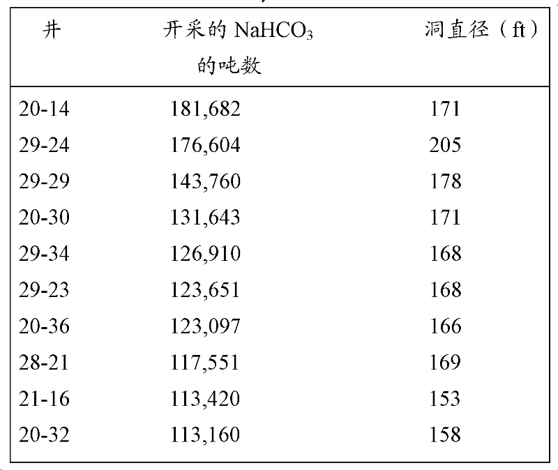
破碎现象影响最佳的井设计和间隔。小孔蛛网井414(参见图4)可能趋向于填满碎石残骸,其能减少原始井附近的渗透性。然而,周围地岩层中的渗透性可能将是大于在图5中所示的计算中所假定的渗透性的,其将通过回流影响热散布。因此,用更少的、更大的、竖直生产井,该处理可同样地或者更好地工作,并且干馏区域可以是更可能围绕水平加热井和在水平加热井之上圆柱形地生长。Fragmentation affects optimal well design and spacing. Small hole spider wells 414 (see FIG. 4 ) may tend to fill with debris debris, which can reduce permeability near the original well. However, it is likely that the permeability in the surrounding formation will be greater than assumed in the calculations shown in Figure 5, which will affect heat dissipation through backflow. Thus, the process may work as well or better with fewer, larger, vertical production wells, and the retort zone may be more likely to grow cylindrically around and above the horizontal heater wells.
CCRTM处理取决于与加热器接触的沸腾油池的维持。在原理上,压力能用作控制油池中油量的方法参数。然而,压力也影响油沸腾所需要的温度。这抑制了可用于优化从加热器传递到周围地岩层的热传递的可用操作参数空间。CCR ™ treatment depends on the maintenance of a boiling oil pool in contact with the heater. In principle, pressure can be used as a method parameter for controlling the oil volume in the sump. However, pressure also affects the temperature required for the oil to boil. This limits the available operating parameter space available to optimize heat transfer from the heater to the surrounding formation.
此外,岩石中的水含量影响维持沸腾油池的能力。通过惰性气体诸如蒸汽能从干馏物清除掉油蒸气;如果生产管道处于气体混合物中的油蒸气的露点以上的温度,油被从干馏物清除掉并且能不再参与回流过程。因此,通过从地面再循环油的油池的补充可能变得是必需的。这种影响在小规模时(例如,对于小规模试验和在较大的测试的启动期间)是最大的,因为水从其蒸发的页岩的量是显著大于干馏的量的。这是因为在干馏物的边界处几乎恒定厚度的页岩已经被干燥而没有被干馏。In addition, the water content in the rock affects the ability to maintain a boiling oil pool. Oil vapor can be purged from the retort by an inert gas such as steam; if the production pipeline is at a temperature above the dew point of the oil vapor in the gas mixture, the oil is purged from the retort and can no longer participate in the reflux process. Therefore, replenishment of the oil sump by recirculating oil from the surface may become necessary. This effect is greatest at small scale (eg, for small scale tests and during start-up of larger tests) because the amount of shale from which water evaporates is significantly greater than the amount of retort. This is because an almost constant thickness of shale at the boundaries of the retort has been dried without being retorted.
通过将热油再循环到干馏物中可以补充输入到干馏区域的热。这需要注入的油的温度超过生产的油蒸气的温度。而且,由于地岩层损坏和热有效率的原因,需要管理从通过其发生再循环的井的热损失。The heat input to the retort zone can be supplemented by recycling hot oil to the retort. This requires the temperature of the injected oil to exceed the temperature of the produced oil vapor. Also, due to formation damage and thermal efficiency reasons, heat loss from the well through which recirculation occurs needs to be managed.
在图9中示出了CCRTM方法的示意性的表示。这个方法具有能独立地优化干馏压力,补偿由蒸汽去除掉的油蒸气,和使用热油再循环增加热输入的量的好处。A schematic representation of the CCR TM method is shown in FIG. 9 . This approach has the advantage of being able to independently optimize retort pressure, compensate for oil vapor removal by steam, and use hot oil recirculation to increase the amount of heat input.
CCRTM干馏设计和操作通常可能受到与离开干馏物进入到蒸气生产井中的气体的温度相关的三个不同的操作阶段的影响。三个阶段与在蒸气生产井的入口处的干馏物温度分布相关。在图10中示意性地示出了以两个热波和三个平稳段为特征的温度与时间的关系,并且所述三个操作阶段对应于三个平稳段。最高温度的平稳段,最接近加热器井,受到油回流波的控制。下一个热平稳段(在流动的方向上)受到水回流波的控制。最低温度的平稳段受到蒸气的显热的控制。随着时间的进行,蒸汽和油回流波与蒸气流一起以由几个关联的热参数支配的速度向上移动。阶段1对应于大约等于周围岩石温度的流出温度。阶段2对应于水在干馏压力下的露点。阶段3对应于油沸腾温度。左图中的等值线表示在三个阶段期间300℃温度曲线的大约范围。CCR ™ retort design and operation may generally be affected by three distinct phases of operation related to the temperature of the gas leaving the retort into the vapor production well. Three phases are associated with the retort temperature profile at the inlet of the steam production well. The temperature versus time characteristic of two thermal waves and three plateaus is schematically shown in FIG. 10 , and the three operating phases correspond to the three plateaus. The plateau of highest temperature, closest to the heater well, is dominated by the oil return wave. The next thermal plateau (in the direction of flow) is dominated by water return waves. The plateau of minimum temperature is governed by the sensible heat of the vapor. Over time, the vapor and oil return waves move upward together with the vapor flow at a velocity governed by several associated thermal parameters.
如同上面所提及的那样,三个操作阶段在离开干馏物并且进入蒸气生产井的蒸气的温度方面是不同的。在第一阶段,流出的未冷凝的气体将它们的热全部沉积到地岩层中,或者几乎如此,并且流出温度基本上处于未加热的页岩温度。在第二阶段,水回流波已经到达了蒸气生产井的出口并且流出温度已经到达了蒸汽平稳段水平,对于150到1100psig的干馏压力来说,其在180到290℃的范围内。在第二阶段期间,大量的水蒸气通过蒸气生产井出口流出。第三阶段的特征是油回流波填充整个干馏物。油回流波致使加热到325到350℃范围内的高温分解温度。生产井入口附近的温度足够高,从而以蒸气的形式携带在干馏物的出口附近中的所有水。对于更高的井压力,仅仅所生产的页岩油的较轻的油馏分参与油回流机制。在全沸腾范围的页岩油的连续产生的情况下,如果不通过油池内的液态生产管去除掉,高沸腾的成分将堆积在油池中。可选地,能允许高沸腾的成分破裂成参与回流机制的较轻成分。As mentioned above, the three stages of operation differ in the temperature of the steam leaving the retort and entering the steam production well. In the first stage, the outflowing uncondensed gases deposit all their heat into the formation, or nearly so, and outflow temperatures are essentially at unheated shale temperatures. In the second stage, the water return wave has reached the outlet of the steam production well and the outflow temperature has reached the steam plateau level, which is in the range of 180 to 290°C for retort pressures of 150 to 1100 psig. During the second stage, a large amount of water vapor flows out through the outlet of the steam production well. The third stage is characterized by oil return waves filling the entire retort. The oil return wave causes heating to pyrolysis temperatures in the range of 325 to 350°C. The temperature near the inlet of the production well is high enough to carry all the water near the outlet of the retort in the form of vapor. For higher well pressures, only the lighter oil fraction of the produced shale oil participates in the oil return mechanism. In the case of continuous production of shale oil in the full boiling range, high boiling components will accumulate in the oil pool if not removed through the liquid production lines within the oil pool. Optionally, high boiling components can be allowed to break down into lighter components that participate in the reflux mechanism.
在第一阶段期间,蒸汽冷凝成液态水并且聚积在干馏物的上部部分中。以稳定流动的方式,液态水沿着壁向下滴流,直到由于与来自下面的流动的蒸气的热交换而使它再次蒸发。然而,流动的不稳定性可能导致液态水一路穿透向下流到油池,在那里它将最终被再次蒸发。如果返回到油池的液态水是大量的,水能变成围绕加热器的支配成分并且将整个油池冷却到水沸腾温度,其低到180℃(低压力的情形)。可能需要从干馏物移除过量水的装置。通过经由加热器高度下面的液态产品管线泵送液态水,或者通过作为时间的函数地使生产井管道的入口移动远离加热器使得它总是逗留在蒸汽平稳段区域,也就是,第二操作阶段,能实现这一点。During the first stage, the vapor condenses into liquid water and accumulates in the upper portion of the retort. In a steady flow, liquid water trickles down the wall until it evaporates again due to heat exchange with the flowing vapor from below. However, flow instabilities can cause liquid water to penetrate all the way down to the oil sump, where it will eventually be evaporated again. If the liquid water returning to the oil sump is substantial, the water can become the dominant component around the heater and cool the entire oil sump to water boiling temperature, which is as low as 180°C (in case of low pressure). Means for removing excess water from the retort may be required. By pumping liquid water through the liquid product line below the height of the heater, or by moving the inlet of the production well tubing away from the heater as a function of time such that it always stays in the steam plateau region, i.e., the second phase of operation , can achieve this.
在最后阶段,大量回流油也作为蒸气被携带出来。因此,这种模式的操作被限制到可得到的油总量,除非能通过从地面或者直接从产品管道入口和地面之间的运输管将油补充到油池延长这个阶段。与干馏内的油回流相反,这个油流动被称作“油再循环”。如果再循环从带外罩的蒸气生产井中的管道系统发生它能是“内部的”,或者如果再循环从地面设备发生它能是“外的”。作为再循环油的替换方案,当油池干涸时干馏能停止。这种方案将需要优化蒸气生产井的设计,使导致干馏的过早终止的通道最小化。可选地,通过将液态油再循环到加热器区域中,干馏操作能继续进行。甚至能以在沸腾油池的正常操作以上的温度注射再循环的油,以提供补充的热输入。然而,期望设计产生良好的蒸气流动模式,使得大部分的热被吸收在干馏边界处,并且不仅仅从地下再循环到地面和返回。具有可调节的油蒸气抽出位置将为热效率优化提供额外的方法。In the final stage, a large amount of return oil is also carried out as vapour. Thus, this mode of operation is limited to the total amount of oil available unless the period can be extended by replenishing oil to the sump either from the surface or directly from the transport line between the product pipeline inlet and the surface. This flow of oil is referred to as "oil recirculation", as opposed to oil return in retorting. Recirculation can be "internal" if it occurs from piping in the shrouded steam production well, or it can be "external" if it occurs from surface equipment. As an alternative to recirculating oil, the retort can be stopped when the oil sump dries up. Such an approach would require optimizing the design of the steam production well to minimize passages leading to premature termination of retort. Optionally, the retort operation can continue by recycling the liquid oil into the heater zone. It is even possible to inject recirculated oil at temperatures above the normal operating temperature of the boiling oil pool to provide supplemental heat input. However, it is desirable that the design produce a good vapor flow pattern such that most of the heat is absorbed at the retort boundary and not recirculated solely from the subsurface to the surface and back. Having an adjustable oil vapor extraction location would provide an additional method for thermal efficiency optimization.
在图11中所示的一个设计中,相对长的倾斜井1102用来使与地岩层的热交换的机会最大化,以逗留在操作阶段1和2的时间为最长的可能时间,从而使对油再循环的需求最小化。从容纳加热器1106的池槽1104的底部泵送液态油和水。池槽和加热器处于主要干馏对象1112下面的低等级油页岩区域1110中。绝热使沸腾油和周围油页岩之间的热传递最小化。从加热器1106出来的热油蒸气将围绕井眼的页岩最先加热到破碎温度并且最终加热到高温分解温度。被干馏的区域1114将沿着暴露的井眼生长,向上的速度大概比向下的速度更快。在这种情形中,尽管用水泥涂覆(cemented)的外罩1120将更可能延伸到大约2050英尺的深度,其是在溶解表面之下大约200英尺处,但是优选的主要干馏对象1112是2080英尺和2130英尺之间的区间。In one design shown in FIG. 11 , relatively long
所需要的再循环油的量取决于生产井管道的入口处的温度,如同在图12中所示的那样。在阶段1的操作期间,从地面的再循环应该是有限的或者应该没有从地面的再循环。油和水生产的主要方法将是作为来自池槽的液体。在325kW的代表性的设计加热器能力时油生产率是大约30bbl/天,但是前面所描述的干馏页岩的干燥更多页岩的问题可将油产量限制到不多于大约15bbl/天。水产量可能高达25bbl/天。如同上面所指出的那样,这些能力和生产率可缩放。例如,在商业规模上,这些生产率可以是十倍或者更多倍。The amount of recirculated oil required depends on the temperature at the inlet of the production well tubing, as shown in FIG. 12 . During
当干馏压力是150psi时,在阶段2的操作中,由于来自干馏区域(生产管的入口)的流出温度达到177℃,水产品从水转换成蒸气。由于通过水蒸气从干馏物剥离掉大量石脑油,需要来自地面设备的再循环石脑油补充加热器井中的油池,以防止它干涸。从干馏加热平衡点的观点来说,优选为在地面设备处将再循环石脑油预热到干馏物流出温度(否则通过再循环进入温度和从干馏物流出的再循环流出温度之间的显热的不同,传递到干馏物的热减少)。为了维持油池和将325kW的热全部传递到干馏物,再循环石脑油将不得不增加,并且在一些估算中,将从150℃的干馏流出温度时的大约75bbl/天增加到177℃的干馏流出温度时的大约115bbl/天,假如离开干馏出口的所有产品之间是热力学平衡的。因此,地面设备应当能在大范围的期望产量,诸如从大约10-145bbl/天中处理再循环油与高温分解页岩油率的组合,以确保足够的油池。然而,取决于井的数量,这个生产量能例如扩大到一百倍。当150psig时的干馏流出温度增加到177℃以上时,转变到阶段3操作。石脑油再循环将不得不增加,并且在一些估算中,将从大约200℃的流出温度时的大约180bbl/天增加到260℃的流出温度时的大约415bbl/天。当干馏压力增加时,再循环的需求降低。When the retort pressure is 150 psi, in
最高热效率处理是在阶段1中操作尽可能长的时间的处理。由于干馏产品输送到地面和从地面输送的热损失被最小化,并且需要最小规模的地面处理设备。油将主要被生产为温液体,并且油气分离需求将是最小的。这意味着待干馏的区域和绝热蒸气生产管的入口之间的经过距离为尽可能的长。当洞生长的更大时,从干馏边界的热损失变得相对更小,并且如果相邻干馏融合在一起,如图3中所示的概念性处理,侧向热损失被补偿,并且当被处理的页岩的厚度变得更大时边缘影响逐步变的更小。The most thermally efficient treatment is the one that operates in
在干馏的最后阶段,整个干馏洞在温度上增到在油的沸腾点是重要的,因为干馏物的底部附近的多孔页岩很可能将支撑大量的油并且防止它作为液体产品排到池槽。因此,蒸气产品管道的入口应当增加到沸腾油池温度。然而,如果为那个目标设计的,这能是干馏寿命的相对短的部分。将需要用于使蒸汽与气体和大量油蒸气闪蒸分离(flash separation)的相对小的设备,以维护在它们的生产接近结束时的干馏面。In the final stages of retort, it is important that the temperature of the entire retort cavity is raised to be at the boiling point of the oil, since the porous shale near the bottom of the retort will likely support the bulk of the oil and prevent it from draining to the sump as a liquid product . Therefore, the inlet to the vapor product line should be increased to boiling oil pool temperature. However, this can be a relatively short portion of the retort life if designed for that goal. Relatively small equipment for flash separation of steam from gases and bulk oil vapors will be required to maintain the retort surfaces near the end of their production.
图13示意性地示出示例性的单个加热器-生产井1310,由六个断层分析井1314围绕的干馏区域1312,和用于处理所生产的油、水和气体的地面设备1320。在图14中所示的位置图的场景中可能最好地描述了装备。图15中示出了测试台(Test Pad)区域1410的放大图。测试台包括加热器-生产井1310和用于处理所产生的流体的设备1320。干馏物1312在TM台1412下面并且由六个断层分析井1324(示出了四个井)围绕。多种井间隔是可预期得到的,诸如井之间的统一距离以及在假定干馏过的区域是梨形时图16中所示的扩大方式。优选为,加热器被放置在略低于R-1干馏区域的池槽中(参见图13),并且油蒸气将流出加热器进入到R-干馏区域中,如同在图11中示意性地示出的那样。Figure 13 schematically shows an exemplary single heater-
参考图17和18,用于干馏的主要热源是电加热器1710。合适的加热器设计的例子是Tyco Thermal Systems。参考图18,冷导线1810是能经受住高温但是自身不产生热的金属氧化物绝缘电缆。通过标准泵电缆1812将三相电力供应到加热器。加热器在预期干馏区域下面的池槽中并且由延伸到地面的四个“针刺(stinger)”管支撑。如同在图19中所表示的那样,Tyco电加热器由三排(bank)三个加热器元件1902、1904和1906组成。通过480伏三相电源给每组的三个元件供电。延伸通过干馏区间的外罩不用水泥涂覆。外罩在干馏的顶部处用水泥涂覆,其是R-1的顶部。稍在那个外罩靴之上的封隔器(packer)1814防止来自干馏的蒸气进入针刺管和涂覆有水泥的外罩之间的环面(annulus)。Referring to Figures 17 and 18, the primary heat source for retort is an
简要地参考图17,油和水从干馏物排到池槽1712中。1.6”的内直径的管1714向下延伸到池槽中并且被用来生产液态油和水。它起到防止水堆积的作用,水堆积能导致油池转换到水沸腾模式,所述水沸腾模式的操作温度太低无法热解页岩。泵是例如气体活塞式泵或气体提升式泵。Referring briefly to FIG. 17 , oil and water drain from the retort into
热油蒸气通过干馏区间的底部附近的穿孔1716流出围绕加热器的外罩。那些穿孔之上的封隔器防止蒸气在产品管和外罩之间向上行进。干馏物内的蒸气加热和热解围绕外罩的页岩。不凝结的气体和油以及水蒸气通过干馏区间的顶部附近的穿孔1718重新进入外罩。在生产环面内凝结的蒸气通过那个相同的环面被向下引导到加热器的下面。略低于上穿孔的封隔器实现液态蒸气的分离并且防止油通过干馏物向下排到热外罩中。Hot oil vapor exits the enclosure surrounding the heater through
通过液体产品管和针刺管之间的2.44”的内直径管1720提供第二环面。内侧环面用来将油从地面再循环到加热器的下面,以维持沸腾油池。在图20中示出了这个的示意性的横截面。通过真空隔热管或其它隔热管道使电缆与热油和蒸气管相分离。金属氧化物绝热加热器电缆可以用来保持生产线的温暖,以防止回流。A second annulus is provided by the 2.44"
地面处理设备将所生产的流体分离成轻油和中油,酸水,以及酸气。任一油馏分能被加热和再循环到地下加热器。气体被输送到焚烧炉,并且水被输送到酸水罐,在那里它能被计量供给到焚烧炉中。油被收集在罐中。大油样本能被转移到卡车中用于非现场研究或使用,并且多余的油能被输送到焚烧炉。在图21中示出了合适的油-水分离系统210的代表性的设计。装备安装在两个8英尺乘以20英尺的滑台上并且优选为被容纳在通风良好的建筑物的内侧。Surface processing equipment separates the produced fluids into light and medium oils, sour water, and sour gas. Either oil fraction can be heated and recycled to an underground heater. The gas is sent to the incinerator and the water is sent to the acid water tank where it can be metered into the incinerator. Oil is collected in tanks. Large oil samples can be transferred to trucks for off-site research or use, and excess oil can be sent to an incinerator. A representative design of a suitable oil-
在另一实施方式中,也在科罗拉多州的Piceance Basin执行CCRTM干馏处理。在这个实施方式中,采矿区间是从大约2015英尺深延伸到大约2135英尺深的大约120英尺厚的部分。In another embodiment, the CCR ™ retort process is also performed at Piceance Basin, Colorado. In this embodiment, the mining interval is an approximately 120 foot thick section extending from approximately 2015 feet deep to approximately 2135 feet deep.
在这个实施方式中,干馏物2202位于由偏斜加热器井2210的两个分支2206(1)和2206(2)连接竖直生产井2204的交叉部分附近,如同在图22中所示的那样。在图23中示出了这个实施方式的整体位置图。竖直生产井2204安装在TM台2310上,而偏斜加热器井2210安装在测试台2312上。在图24中示出了测试台和TM台区域的放大图。除了加热器井之外,测试台也包括用于处理所生产的流体的设备2212。干馏物在TM台的下面并且由多个断层分析井围绕,如同在图25中所示的那样。在这个实施例中,六个断层分析井围绕干馏物。根据情况许可,断层分析井的精确数量和位置可以变化。加热器2610优选为被放置在略低于R-1区域的密封管中,并且油蒸气将流出加热器进入到R-1区域中,如同在图26中示意性地所示的那样。In this embodiment, the retort 2202 is located near the intersection of the vertical production well 2204 connected by the two branches 2206(1) and 2206(2) of the deviated heater well 2210, as shown in FIG. . An overall positional view of this embodiment is shown in FIG. 23 .
地面处理设备2212将所生产的流体分离成轻油和中油,酸水,以及酸气。任一油馏分能被加热并且被再循环到地下井底电加热器。气体可以被输送到焚烧炉,并且水被输送到酸水罐,从其将水计量供给到焚烧炉中。油被收集在罐中。大油样本能被转移到卡车上用于非现场研究或使用,并且多余的油能被输送到焚烧炉。The surface processing facility 2212 separates the produced fluids into light and medium oils, sour water, and sour gas. Either oil fraction can be heated and recycled to the underground bottomhole electric heater. The gas may be sent to the incinerator and the water sent to the acid water tank from which the water is metered into the incinerator. Oil is collected in tanks. Large oil samples can be transferred to trucks for off-site research or use, and excess oil can be sent to an incinerator.
如图27和28所示的加热器组件2610可以用来使页岩油沸腾。加热器组件包括电加热元件2710和容纳在密封“加热器管”2714中的传热流体2712-它们全部都被浸没在预期干馏区间下面的页岩油中。电加热元件被附接到延伸到地面的“加热器脐带”管2716(名义上是23/8英寸,如同在图28中所示的那样)。添加足够的传热流体,以浸没电加热元件。A
参考图28,加热器组件使页岩油沸腾,提供用来加热干馏物的热蒸气。蒸气提供显热和潜热。凝结蒸气提供潜热。凝结物流回到沸腾油池,在那里它被在“生产液体管”2812中从在生产井的底部附近的池槽2814作为水/油混合物的一部分被泵送到地面,或者被加热器组件再次沸腾。“地面回流”管2816用来将油从地面处理设备再循环回到干馏物中。这两个管被一起用来维持干馏物中的油的蒸气的水平。“蒸气输出管”2810用来将未凝结的蒸气传递到地面。沸腾所述油给测试干馏物加压,并且干馏物压力主要受到这个管中的蒸气在地面处的节流的控制。Referring to Figure 28, the heater assembly boils the shale oil, providing hot vapor that is used to heat the retort. Vapor provides sensible and latent heat. The condensing vapor provides latent heat. The condensate flows back to the boiling oil sump where it is pumped to the surface as part of the water/oil mixture in the "production liquid line" 2812 from
图29-30示出了有助于干馏物中的对流传热的几个可选井构造的几何形状。例如,图29示出了沿着加热器井眼的水平部分的100英尺长的CCRTM干馏。在这个构造中,通过竖直生产井生产页岩油。图30示出了通过钻具有分支的水平井3020和两个竖直井3030、3032的循环模式增强的传热对流环3010。应当认识到,在附图中示出的三角形的和四边形的对流环仅仅是能形成的增强对流的几何形状的例子。Figures 29-30 illustrate several alternative well configuration geometries to facilitate convective heat transfer in the retort. For example, Figure 29 shows a 100 foot long CCR ™ retort along a horizontal section of a heater wellbore. In this configuration, shale oil is produced through vertical production wells. FIG. 30 shows a heat
因此,已经一些程度地尤其涉及代表性的实施方式地描述了本发明的技术。应当理解,但是,本发明的技术由根据现有技术解释的下面的权利要求限定,使得在不脱离这里所包含的创造性的概念的情况下可以对代表性的实施方式进行修改或改变。Thus, the technology of the present invention has been described somewhat, particularly with regard to representative embodiments. It should be understood, however, that the technology of the present invention is defined by the following claims construed in light of the prior art such that modifications or changes may be made to the representative embodiments without departing from the inventive concepts contained herein.
Claims (23)
Applications Claiming Priority (5)
| Application Number | Priority Date | Filing Date | Title |
|---|---|---|---|
| US17885609P | 2009-05-15 | 2009-05-15 | |
| US61/178,856 | 2009-05-15 | ||
| US32851910P | 2010-04-27 | 2010-04-27 | |
| US61/328,519 | 2010-04-27 | ||
| PCT/US2010/034790 WO2010132704A2 (en) | 2009-05-15 | 2010-05-13 | In situ method and system for extraction of oil from shale |
Publications (2)
| Publication Number | Publication Date |
|---|---|
| CN102428252A true CN102428252A (en) | 2012-04-25 |
| CN102428252B CN102428252B (en) | 2015-07-15 |
Family
ID=43085584
Family Applications (1)
| Application Number | Title | Priority Date | Filing Date |
|---|---|---|---|
| CN201080021196.2A Active CN102428252B (en) | 2009-05-15 | 2010-05-13 | In situ method and system for extraction of oil from shale |
Country Status (5)
| Country | Link |
|---|---|
| US (2) | US7921907B2 (en) |
| CN (1) | CN102428252B (en) |
| CA (1) | CA2760967C (en) |
| IL (1) | IL216332A (en) |
| WO (1) | WO2010132704A2 (en) |
Cited By (1)
| Publication number | Priority date | Publication date | Assignee | Title |
|---|---|---|---|---|
| CN107558950A (en) * | 2017-09-13 | 2018-01-09 | 吉林大学 | Orientation blocking method for the closing of oil shale underground in situ production zone |
Families Citing this family (46)
| Publication number | Priority date | Publication date | Assignee | Title |
|---|---|---|---|---|
| IL152455A0 (en) | 2000-04-24 | 2003-05-29 | Shell Int Research | In situ recovery of hydrocarbons from a kerogen-containing formation |
| CA2564515C (en) | 2004-04-23 | 2013-06-18 | Shell Internationale Research Maatschappij B.V. | Temperature limited heaters used to heat subsurface formations |
| US8027571B2 (en) | 2005-04-22 | 2011-09-27 | Shell Oil Company | In situ conversion process systems utilizing wellbores in at least two regions of a formation |
| US7683296B2 (en) | 2006-04-21 | 2010-03-23 | Shell Oil Company | Adjusting alloy compositions for selected properties in temperature limited heaters |
| CA2666956C (en) | 2006-10-20 | 2016-03-22 | Shell Internationale Research Maatschappij B.V. | Heating tar sands formations to visbreaking temperatures |
| AU2008242796B2 (en) | 2007-04-20 | 2011-07-07 | Shell Internationale Research Maatschappij B.V. | Electrically isolating insulated conductor heater |
| CA2700732A1 (en) | 2007-10-19 | 2009-04-23 | Shell Internationale Research Maatschappij B.V. | Cryogenic treatment of gas |
| AU2009251533B2 (en) | 2008-04-18 | 2012-08-23 | Shell Internationale Research Maatschappij B.V. | Using mines and tunnels for treating subsurface hydrocarbon containing formations |
| JP5611962B2 (en) | 2008-10-13 | 2014-10-22 | シエル・インターナシヨナル・リサーチ・マートスハツペイ・ベー・ヴエー | Circulating heat transfer fluid system used to treat ground surface underlayer |
| WO2010118315A1 (en) | 2009-04-10 | 2010-10-14 | Shell Oil Company | Treatment methodologies for subsurface hydrocarbon containing formations |
| CA2784496A1 (en) * | 2009-12-15 | 2011-07-14 | Chevron U.S.A. Inc. | System, method and assembly for wellbore maintenance operations |
| US8701768B2 (en) | 2010-04-09 | 2014-04-22 | Shell Oil Company | Methods for treating hydrocarbon formations |
| US8875788B2 (en) | 2010-04-09 | 2014-11-04 | Shell Oil Company | Low temperature inductive heating of subsurface formations |
| US8939207B2 (en) | 2010-04-09 | 2015-01-27 | Shell Oil Company | Insulated conductor heaters with semiconductor layers |
| US9127523B2 (en) | 2010-04-09 | 2015-09-08 | Shell Oil Company | Barrier methods for use in subsurface hydrocarbon formations |
| US8631866B2 (en) | 2010-04-09 | 2014-01-21 | Shell Oil Company | Leak detection in circulated fluid systems for heating subsurface formations |
| US8502120B2 (en) | 2010-04-09 | 2013-08-06 | Shell Oil Company | Insulating blocks and methods for installation in insulated conductor heaters |
| US8955591B1 (en) | 2010-05-13 | 2015-02-17 | Future Energy, Llc | Methods and systems for delivery of thermal energy |
| WO2012024541A1 (en) | 2010-08-18 | 2012-02-23 | Future Energy Llc | Methods and systems for enhanced delivery of thermal energy for horizontal wellbores |
| US8732946B2 (en) | 2010-10-08 | 2014-05-27 | Shell Oil Company | Mechanical compaction of insulator for insulated conductor splices |
| US8943686B2 (en) | 2010-10-08 | 2015-02-03 | Shell Oil Company | Compaction of electrical insulation for joining insulated conductors |
| US8857051B2 (en) | 2010-10-08 | 2014-10-14 | Shell Oil Company | System and method for coupling lead-in conductor to insulated conductor |
| US9033033B2 (en) | 2010-12-21 | 2015-05-19 | Chevron U.S.A. Inc. | Electrokinetic enhanced hydrocarbon recovery from oil shale |
| US8997869B2 (en) | 2010-12-22 | 2015-04-07 | Chevron U.S.A. Inc. | In-situ kerogen conversion and product upgrading |
| US9016370B2 (en) | 2011-04-08 | 2015-04-28 | Shell Oil Company | Partial solution mining of hydrocarbon containing layers prior to in situ heat treatment |
| RU2612774C2 (en) | 2011-10-07 | 2017-03-13 | Шелл Интернэшнл Рисерч Маатсхаппий Б.В. | Thermal expansion accommodation for systems with circulating fluid medium, used for rocks thickness heating |
| US8701788B2 (en) | 2011-12-22 | 2014-04-22 | Chevron U.S.A. Inc. | Preconditioning a subsurface shale formation by removing extractible organics |
| US8851177B2 (en) | 2011-12-22 | 2014-10-07 | Chevron U.S.A. Inc. | In-situ kerogen conversion and oxidant regeneration |
| US9181467B2 (en) | 2011-12-22 | 2015-11-10 | Uchicago Argonne, Llc | Preparation and use of nano-catalysts for in-situ reaction with kerogen |
| AU2012367826A1 (en) | 2012-01-23 | 2014-08-28 | Genie Ip B.V. | Heater pattern for in situ thermal processing of a subsurface hydrocarbon containing formation |
| WO2013112133A1 (en) | 2012-01-23 | 2013-08-01 | Genie Ip B.V. | Heater pattern for in situ thermal processing of a subsurface hydrocarbon containing formation |
| AU2013221197A1 (en) * | 2012-02-18 | 2014-08-28 | Genie Ip B.V. | Method and system for heating a bed of hydrocarbon- containing rocks |
| US8726986B2 (en) | 2012-04-19 | 2014-05-20 | Harris Corporation | Method of heating a hydrocarbon resource including lowering a settable frequency based upon impedance |
| US8992771B2 (en) | 2012-05-25 | 2015-03-31 | Chevron U.S.A. Inc. | Isolating lubricating oils from subsurface shale formations |
| US20140014327A1 (en) * | 2012-07-13 | 2014-01-16 | Schlumberger Technology Corporation | Methodology and system for producing fluids from a condensate gas reservoir |
| US9303499B2 (en) | 2012-10-18 | 2016-04-05 | Elwha Llc | Systems and methods for enhancing recovery of hydrocarbon deposits |
| US20150285032A1 (en) * | 2012-10-30 | 2015-10-08 | Genie Ip B.V. | Methods and apparatus for storage and recovery of hydrocarbon fluids |
| US11242735B2 (en) | 2013-02-08 | 2022-02-08 | Chevron U.S.A. Inc. | System and process for recovering hydrocarbons using a supercritical fluid |
| US10907455B2 (en) * | 2013-02-08 | 2021-02-02 | Chevron U.S.A. Inc. | System and process for recovering hydrocarbons using a supercritical fluid |
| US20150101814A1 (en) * | 2013-08-21 | 2015-04-16 | Genie Ip B.V. | Method and system for heating a bed of rocks containing sulfur-rich type iis kerogen |
| WO2016178046A1 (en) | 2015-05-05 | 2016-11-10 | Total Sa | Downhole heating device to be introduced in a well bored in an underground formation containing a solid hydrocarbonaceous layer, related installation, and method |
| US10718191B2 (en) * | 2015-06-26 | 2020-07-21 | University of Louisana at Lafayette | Method for enhancing hydrocarbon production from unconventional shale reservoirs |
| US10920152B2 (en) | 2016-02-23 | 2021-02-16 | Pyrophase, Inc. | Reactor and method for upgrading heavy hydrocarbons with supercritical fluids |
| CN107474868B (en) * | 2017-09-29 | 2023-06-27 | 新疆国利衡清洁能源科技有限公司 | Underground oil production system of oil shale and oil production method thereof |
| GB2579214B (en) * | 2018-11-23 | 2021-06-02 | Cavitas Energy Ltd | Downhole fluid heater and associated methods |
| CN117803363A (en) * | 2024-01-24 | 2024-04-02 | 中国石油大学(北京) | An in-situ oil shale development method that reduces the risk of groundwater contamination |
Citations (3)
| Publication number | Priority date | Publication date | Assignee | Title |
|---|---|---|---|---|
| US4408665A (en) * | 1977-05-03 | 1983-10-11 | Equity Oil Company | In situ recovery of oil and gas from water-flooded oil shale formations |
| US20070181301A1 (en) * | 2006-02-06 | 2007-08-09 | O'brien Thomas B | Method and system for extraction of hydrocarbons from oil shale |
| US20070193743A1 (en) * | 2006-01-20 | 2007-08-23 | Harris Harry G | In situ method and system for extraction of oil from shale |
Family Cites Families (6)
| Publication number | Priority date | Publication date | Assignee | Title |
|---|---|---|---|---|
| US5816325A (en) * | 1996-11-27 | 1998-10-06 | Future Energy, Llc | Methods and apparatus for enhanced recovery of viscous deposits by thermal stimulation |
| IL152455A0 (en) * | 2000-04-24 | 2003-05-29 | Shell Int Research | In situ recovery of hydrocarbons from a kerogen-containing formation |
| AU2001263178A1 (en) * | 2000-05-16 | 2001-11-26 | Andrew M. Ashby | Method and apparatus for hydrocarbon subterranean recovery |
| US6918443B2 (en) * | 2001-04-24 | 2005-07-19 | Shell Oil Company | In situ thermal processing of an oil shale formation to produce hydrocarbons having a selected carbon number range |
| US20050103497A1 (en) * | 2003-11-17 | 2005-05-19 | Michel Gondouin | Downhole flow control apparatus, super-insulated tubulars and surface tools for producing heavy oil by steam injection methods from multi-lateral wells located in cold environments |
| US8027571B2 (en) * | 2005-04-22 | 2011-09-27 | Shell Oil Company | In situ conversion process systems utilizing wellbores in at least two regions of a formation |
-
2010
- 2010-05-13 US US12/779,791 patent/US7921907B2/en active Active
- 2010-05-13 CN CN201080021196.2A patent/CN102428252B/en active Active
- 2010-05-13 WO PCT/US2010/034790 patent/WO2010132704A2/en not_active Ceased
- 2010-05-13 CA CA2760967A patent/CA2760967C/en active Active
-
2011
- 2011-03-03 US US13/039,847 patent/US8162043B2/en active Active
- 2011-11-13 IL IL216332A patent/IL216332A/en active IP Right Grant
Patent Citations (3)
| Publication number | Priority date | Publication date | Assignee | Title |
|---|---|---|---|---|
| US4408665A (en) * | 1977-05-03 | 1983-10-11 | Equity Oil Company | In situ recovery of oil and gas from water-flooded oil shale formations |
| US20070193743A1 (en) * | 2006-01-20 | 2007-08-23 | Harris Harry G | In situ method and system for extraction of oil from shale |
| US20070181301A1 (en) * | 2006-02-06 | 2007-08-09 | O'brien Thomas B | Method and system for extraction of hydrocarbons from oil shale |
Cited By (1)
| Publication number | Priority date | Publication date | Assignee | Title |
|---|---|---|---|---|
| CN107558950A (en) * | 2017-09-13 | 2018-01-09 | 吉林大学 | Orientation blocking method for the closing of oil shale underground in situ production zone |
Also Published As
| Publication number | Publication date |
|---|---|
| CA2760967A1 (en) | 2010-11-18 |
| CA2760967C (en) | 2017-08-29 |
| WO2010132704A2 (en) | 2010-11-18 |
| US7921907B2 (en) | 2011-04-12 |
| US20100288497A1 (en) | 2010-11-18 |
| CN102428252B (en) | 2015-07-15 |
| IL216332A0 (en) | 2012-01-31 |
| US20110174496A1 (en) | 2011-07-21 |
| IL216332A (en) | 2014-12-31 |
| WO2010132704A3 (en) | 2011-03-31 |
| US8162043B2 (en) | 2012-04-24 |
Similar Documents
| Publication | Publication Date | Title |
|---|---|---|
| CN102428252B (en) | In situ method and system for extraction of oil from shale | |
| CN102947539B (en) | conduction convection reflux retort method | |
| CN100400793C (en) | Method and system for in-situ heating of a hydrocarbon-bearing formation through a U-shaped opening | |
| CN102187054B (en) | Circulated heated transfer fluid heating of subsurface hydrocarbon formations | |
| CN101680287B (en) | Heating systems for heating subsurface formations and method for heating subsurface formations | |
| CN102007266B (en) | Systems and methods for treating subterranean hydrocarbon-bearing formations | |
| US7743826B2 (en) | In situ method and system for extraction of oil from shale | |
| CN106460486A (en) | Thermal energy delivery and oil production arrangements and methods thereof | |
| WO2013016685A1 (en) | Apparatus and methods for recovery of hydrocarbons | |
| EA014196B1 (en) | Systems and methods for producing hydrocarbons from tar sands with heat created drainage paths | |
| CN101292011A (en) | Apparatus, system and method for on-site extraction of oil from oil shale | |
| US8893793B2 (en) | Apparatus and methods for the recovery of hydrocarbonaceous and additional products from oil shale and oil sands | |
| RU2319830C2 (en) | Method and device for hydrocarbon reservoir interior heating along with exposing thereof to ground surface in two locations | |
| US20160265327A1 (en) | Steam assisted gravity drainage with added oxygen ("sagdox") in deep reservoirs | |
| CN100359128C (en) | Method for preventing wellbore deformation during in situ thermal treatment of hydrocarbon containing formations | |
| WO2023059896A1 (en) | Geothermal heating of hydrocarbon reservoirs for in situ recovery | |
| WO2014089685A1 (en) | Steam assisted gravity drainage with added oxygen ("sagdox") in deep reservoirs | |
| US20150285032A1 (en) | Methods and apparatus for storage and recovery of hydrocarbon fluids | |
| CA3133630A1 (en) | Geothermal heating of hydrocarbon reservoirs for in situ recovery | |
| CN104763396A (en) | Systems and methods for producing hydrocarbons from tar sands with heat created drainage paths | |
| IL222203A (en) | Methods and apparatus for storage and recovery of hydrocarbon fluids |
Legal Events
| Date | Code | Title | Description |
|---|---|---|---|
| C06 | Publication | ||
| PB01 | Publication | ||
| C10 | Entry into substantive examination | ||
| SE01 | Entry into force of request for substantive examination | ||
| C14 | Grant of patent or utility model | ||
| GR01 | Patent grant |