CN102422163A - Method and apparatus for implementing reaction vessel transfer in an instrument for a multi-step analytical procedure - Google Patents
Method and apparatus for implementing reaction vessel transfer in an instrument for a multi-step analytical procedure Download PDFInfo
- Publication number
- CN102422163A CN102422163A CN2010800206269A CN201080020626A CN102422163A CN 102422163 A CN102422163 A CN 102422163A CN 2010800206269 A CN2010800206269 A CN 2010800206269A CN 201080020626 A CN201080020626 A CN 201080020626A CN 102422163 A CN102422163 A CN 102422163A
- Authority
- CN
- China
- Prior art keywords
- container
- balladeur train
- door
- pan straddle
- make
- Prior art date
- Legal status (The legal status is an assumption and is not a legal conclusion. Google has not performed a legal analysis and makes no representation as to the accuracy of the status listed.)
- Granted
Links
Images


Classifications
-
- B—PERFORMING OPERATIONS; TRANSPORTING
- B65—CONVEYING; PACKING; STORING; HANDLING THIN OR FILAMENTARY MATERIAL
- B65G—TRANSPORT OR STORAGE DEVICES, e.g. CONVEYORS FOR LOADING OR TIPPING, SHOP CONVEYOR SYSTEMS OR PNEUMATIC TUBE CONVEYORS
- B65G47/00—Article or material-handling devices associated with conveyors; Methods employing such devices
- B65G47/74—Feeding, transfer, or discharging devices of particular kinds or types
- B65G47/90—Devices for picking-up and depositing articles or materials
- B65G47/901—Devices for picking-up and depositing articles or materials provided with drive systems with rectilinear movements only
-
- G—PHYSICS
- G01—MEASURING; TESTING
- G01N—INVESTIGATING OR ANALYSING MATERIALS BY DETERMINING THEIR CHEMICAL OR PHYSICAL PROPERTIES
- G01N35/00—Automatic analysis not limited to methods or materials provided for in any single one of groups G01N1/00 - G01N33/00; Handling materials therefor
- G01N35/02—Automatic analysis not limited to methods or materials provided for in any single one of groups G01N1/00 - G01N33/00; Handling materials therefor using a plurality of sample containers moved by a conveyor system past one or more treatment or analysis stations
- G01N35/04—Details of the conveyor system
- G01N2035/0401—Sample carriers, cuvettes or reaction vessels
- G01N2035/0412—Block or rack elements with a single row of samples
- G01N2035/0413—Block or rack elements with a single row of samples moving in one dimension
-
- G—PHYSICS
- G01—MEASURING; TESTING
- G01N—INVESTIGATING OR ANALYSING MATERIALS BY DETERMINING THEIR CHEMICAL OR PHYSICAL PROPERTIES
- G01N35/00—Automatic analysis not limited to methods or materials provided for in any single one of groups G01N1/00 - G01N33/00; Handling materials therefor
- G01N35/02—Automatic analysis not limited to methods or materials provided for in any single one of groups G01N1/00 - G01N33/00; Handling materials therefor using a plurality of sample containers moved by a conveyor system past one or more treatment or analysis stations
- G01N35/04—Details of the conveyor system
- G01N2035/0401—Sample carriers, cuvettes or reaction vessels
- G01N2035/0418—Plate elements with several rows of samples
- G01N2035/0422—Plate elements with several rows of samples carried on a linear conveyor
-
- G—PHYSICS
- G01—MEASURING; TESTING
- G01N—INVESTIGATING OR ANALYSING MATERIALS BY DETERMINING THEIR CHEMICAL OR PHYSICAL PROPERTIES
- G01N35/00—Automatic analysis not limited to methods or materials provided for in any single one of groups G01N1/00 - G01N33/00; Handling materials therefor
- G01N35/02—Automatic analysis not limited to methods or materials provided for in any single one of groups G01N1/00 - G01N33/00; Handling materials therefor using a plurality of sample containers moved by a conveyor system past one or more treatment or analysis stations
- G01N35/04—Details of the conveyor system
- G01N2035/0474—Details of actuating means for conveyors or pipettes
- G01N2035/0482—Transmission
- G01N2035/0484—Belt or chain
-
- G—PHYSICS
- G01—MEASURING; TESTING
- G01N—INVESTIGATING OR ANALYSING MATERIALS BY DETERMINING THEIR CHEMICAL OR PHYSICAL PROPERTIES
- G01N35/00—Automatic analysis not limited to methods or materials provided for in any single one of groups G01N1/00 - G01N33/00; Handling materials therefor
- G01N35/02—Automatic analysis not limited to methods or materials provided for in any single one of groups G01N1/00 - G01N33/00; Handling materials therefor using a plurality of sample containers moved by a conveyor system past one or more treatment or analysis stations
- G01N35/026—Automatic analysis not limited to methods or materials provided for in any single one of groups G01N1/00 - G01N33/00; Handling materials therefor using a plurality of sample containers moved by a conveyor system past one or more treatment or analysis stations having blocks or racks of reaction cells or cuvettes
Landscapes
- Analytical Chemistry (AREA)
- Physics & Mathematics (AREA)
- Health & Medical Sciences (AREA)
- Life Sciences & Earth Sciences (AREA)
- Chemical & Material Sciences (AREA)
- Biochemistry (AREA)
- General Health & Medical Sciences (AREA)
- General Physics & Mathematics (AREA)
- Immunology (AREA)
- Pathology (AREA)
- Mechanical Engineering (AREA)
- Engineering & Computer Science (AREA)
- Automatic Analysis And Handling Materials Therefor (AREA)
Abstract
Description
背景background
相关申请的交叉引用Cross References to Related Applications
本申请要求根据35U.S.C.119(e)于2009年5月15日提交的美国临时申请号61/178,728的权益,该专利的公开内容以全文引用方式并入本文。This application claims the benefit of US Provisional Application No. 61/178,728 filed May 15, 2009 under 35 U.S.C. 119(e), the disclosure of which is incorporated herein by reference in its entirety.
技术领域 technical field
本发明涉及用于在进行多步骤分析工序的仪器的模块之间实现反应容器传送和用于自动调节这些模块的位置变化的系统、方法和设备。The present invention relates to systems, methods and apparatus for enabling reaction vessel transfer between modules of an instrument for performing multi-step analytical procedures and for automatically adjusting the positional changes of these modules.
背景技术 Background technique
本文引用的所有文献或指定部分均以引用方式并入本文。然而,没有文献被承认是所要求保护的主题的现有技术。All documents or designated portions cited herein are hereby incorporated by reference. However, no document is admitted to be prior art with the claimed subject matter.
本领域中已知具有多种模块的仪器,多步骤工序中的一个或多个步骤将在所述模块中进行。这些仪器的设计和操作中的难题是设计一种在仪器的不同模块之间高效传送容器的方式,反应(例如化学、生物化学或生物)在所述容器中进行(下文中称为“反应容器”)。在仪器中的模块通常进行替换或取出以便维护,然后重新安装,因此,容器传送位置的精确定位可能变化,且不能完全精确地知道。因此,用于在模块之间传送反应容器的任意装置或设备必须布置的精确位置不可能精确知道。Apparatus are known in the art having various modules in which one or more steps of a multi-step process are to be performed. A challenge in the design and operation of these instruments is devising a way to efficiently transport the vessels in which reactions (e.g., chemical, biochemical, or biological) take place (hereinafter referred to as "reaction vessels") between the different modules of the instrument. "). Modules in the instrument are usually replaced or taken out for maintenance and then reinstalled, so the precise location of the container transfer location may vary and cannot be known with perfect accuracy. Thus, the precise location where any means or equipment for transferring reaction vessels between modules must be placed cannot be known with precision.
发明内容 Contents of the invention
本发明的多个方面通过用于在多个容器接收结构之间传送一个或多个容器的设备来实现。该设备包括输送轨道、容器支架以及传送位置定位系统。所述输送轨道有相对端,且所述容器接收结构布置在邻近输送轨道的不同位置处。与输送轨道操作地接合的容器支架适于承载容器以及在轨道的相对端之间沿第一或第二方向沿输送轨道平移。容器支架还适于相对布置在邻近输送轨道的容器接收结构的任一容器接收结构选择地停止在传送位置,且容器支架包括容器运动机构,所述容器运动机构适于使得容器相对于容器支架运动,以便使得容器运动进入容器支架、运动离开容器支架、或者选择地运动进入和运动离开容器支架。传送位置定位系统适于对于各容器接收结构自动确定容器支架相对于容器接收结构的传送位置的定位,以便使得容器支架能够在容器支架和容器接收结构之间传送容器。Aspects of the invention are implemented by an apparatus for transferring one or more containers between a plurality of container receiving structures. The equipment includes conveying track, container support and conveying position positioning system. The conveyor track has opposite ends, and the container receiving structures are arranged at different locations adjacent the conveyor track. A container holder operatively engaged with the conveying track is adapted to carry a container and to translate along the conveying track in a first or second direction between opposite ends of the track. The container holder is further adapted to be selectively stopped in a transfer position relative to any container receiving structure disposed adjacent the conveying track, and the container holder includes a container movement mechanism adapted to move the container relative to the container holder , so as to cause the container to move into the container holder, move out of the container holder, or selectively move into and out of the container holder. The transfer position positioning system is adapted for automatically determining, for each container receiving structure, the positioning of the transfer position of the container holder relative to the container receiving structure in order to enable the container holder to transfer containers between the container holder and the container receiving structure.
根据本发明的其他多个方面,输送轨道包括基部部分、竖直背衬部分、安装在基部部分上的引导轨道以及安装在竖直部分上的导轨。容器支架的一部分与引导轨道和导轨接合。在特定实施例中,输送轨道为线性,且在特定实施例中,输送轨道为基本上水平的。According to other aspects of the invention, a conveyor track includes a base portion, a vertical backing portion, a guide rail mounted on the base portion, and a guide rail mounted on the vertical portion. A portion of the container holder is engaged with the guide track and the guide rail. In certain embodiments, the conveying track is linear, and in certain embodiments, the conveying track is substantially horizontal.
根据本发明的还有一些方面,设备包括:支架平移系统,所述支架平移系统适于实现容器支架沿输送轨道的动力平移;支架升高系统,所述支架升高系统适于使得容器支架的至少一部分相对于输送轨道沿横向方向运动;和/或支架旋转系统,所述支架旋转系统适于使得容器支架的至少一部分绕旋转轴线旋转。According to still some aspects of the present invention, the equipment includes: a rack translation system, which is adapted to realize the dynamic translation of the container rack along the conveying track; and a rack lifting system, which is adapted to make the container rack At least a portion moves in a transverse direction relative to the conveyor track; and/or a rack rotation system adapted to rotate at least a portion of the container rack about an axis of rotation.
在一个实施例中,支架平移系统包括:平移驱动电机,所述平移驱动电机有输出轴;支架驱动皮带,所述支架驱动皮带与容器支架联接;以及一个或多个皮带轮,所述一个或多个皮带轮支承支架驱动皮带。支架驱动皮带与平移驱动电机的输出轴联接,以使得输出轴的旋转经由支架驱动皮带而转变成容器支架沿输送轨道的平移。In one embodiment, the rack translation system includes: a translation drive motor having an output shaft; a rack drive belt coupled to the container rack; and one or more pulleys, the one or more A pulley support bracket drives the belt. The carriage drive belt is coupled to the output shaft of the translation drive motor such that rotation of the output shaft is translated via the carriage drive belt into translation of the container carriage along the conveyor track.
在一个实施例中,设备包括编码器,所述编码器与平移驱动电机联接,用于监测输出轴的旋转。In one embodiment, the apparatus includes an encoder coupled to the translation drive motor for monitoring rotation of the output shaft.
在一个实施例中,设备包括皮带张紧器,所述皮带张紧器构造成在支架驱动皮带中施加张力。In one embodiment, the apparatus includes a belt tensioner configured to apply tension in the carriage drive belt.
在一个实施例中,设备包括支架位置传感器,所述支架位置传感器构造成检测容器支架何时处于输送轨道上的特定位置。In one embodiment, the apparatus includes a rack position sensor configured to detect when a container rack is in a particular position on the conveying track.
在一个实施例中,输送轨道基本水平,支架升高系统适于使得容器支架的至少一部分相对于输送轨道沿竖直方向运动。In one embodiment, the transport track is substantially horizontal and the rack raising system is adapted to move at least a portion of the container rack in a vertical direction relative to the transport track.
在一个实施例中,支架升高系统包括:升高驱动电机,所述升高驱动电机具有输出轴;驱动丝杠,所述驱动丝杠具有纵向轴线,并与升高驱动电机操作地联接,用于驱动丝杠的动力旋转;以及升高块,所述升高块与驱动丝杠联接,以使得驱动丝杠的旋转使得升高块沿驱动丝杠的纵向轴线平移;容器支架的至少一部分承载在升高块上。In one embodiment, a rack raising system includes a raising drive motor having an output shaft, a drive lead screw having a longitudinal axis and operatively coupled to the raising drive motor, for powered rotation of the drive screw; and a raised block coupled to the drive screw such that rotation of the drive screw translates the raised block along the longitudinal axis of the drive screw; at least a portion of the vessel holder Carried on raised blocks.
在一个实施例中,设备包括编码器,所述编码器与升高驱动电机联接,用于监测输出轴的旋转。In one embodiment, the apparatus includes an encoder coupled to the lift drive motor for monitoring rotation of the output shaft.
在一个实施例中,设备包括升高位置传感器,所述升高位置传感器构造成检测容器支架的至少一部分何时离输送轨道一特定横向距离。In one embodiment, the apparatus includes a raised position sensor configured to detect when at least a portion of the container holder is a particular lateral distance from the conveying track.
在一个实施例中,输送轨道基本水平,且支架旋转系统适于使得容器支架绕基本竖直的旋转轴线旋转。In one embodiment, the delivery track is substantially horizontal and the rack rotation system is adapted to rotate the container rack about a substantially vertical axis of rotation.
在一个实施例中,支架旋转系统包括:旋转驱动电机,所述旋转驱动电机具有输出轴;驱动齿轮,所述驱动齿轮与输出轴联接;以及平台齿轮,所述平台齿轮安装成可绕旋转轴线旋转,并与驱动齿轮联接,用于平台齿轮的动力旋转;且容器支架的至少一部分承载在平台齿轮上。In one embodiment, a stand rotation system includes: a rotation drive motor having an output shaft; a drive gear coupled to the output shaft; and a platform gear mounted about an axis of rotation rotates, and is coupled with the drive gear for powered rotation of the platform gear; and at least a portion of the container support is carried on the platform gear.
在一个实施例中,设备还包括编码器,所述编码器与旋转驱动电机联接,用于监测输出轴的旋转。In one embodiment, the apparatus further includes an encoder coupled to the rotary drive motor for monitoring rotation of the output shaft.
在一个实施例中,设备还包括旋转位置传感器,所述旋转位置传感器构造成检测容器支架的至少一部分何时处于绕旋转轴线的一特定旋转位置。In one embodiment, the apparatus further comprises a rotational position sensor configured to detect when at least a portion of the vessel holder is in a particular rotational position about the axis of rotation.
在一个实施例中,容器运动机构包括:容器接合装置,所述容器接合装置构造成与容器可释放地接合,以便能够物理操纵接合的容器;以及容器驱动电机,所述容器驱动电机具有输出轴,输出轴与容器接合装置联接,用于实现容器接合装置的动力运动。In one embodiment, the container movement mechanism includes: a container engagement device configured to releasably engage with the container to enable physical manipulation of the engaged container; and a container drive motor having an output shaft , the output shaft is coupled with the container engaging device for realizing the power movement of the container engaging device.
在一个实施例中,容器接合装置包括钩。In one embodiment, the container engaging means comprises a hook.
在一个实施例中,容器接合装置承载在接合装置滑架上,且容器运动机构还包括:容器导轨,所述接合装置滑架可平移地承载在容器导轨上;容器驱动皮带,所述容器驱动皮带与接合装置滑架联接;以及一个或多个皮带轮,所述皮带轮支承容器驱动皮带轮。容器驱动皮带与容器驱动电机的输出轴联接,以使得输出轴的旋转经由容器驱动皮带而转变成接合装置滑架沿容器导轨的平移。In one embodiment, the container engaging device is carried on an engaging device carriage, and the container moving mechanism further comprises: a container guide rail on which the engaging device carriage is translatably carried; a container driving belt, and the container driving a belt coupled to the engagement device carriage; and one or more pulleys supporting the container drive pulley. The pod drive belt is coupled to the output shaft of the pod drive motor such that rotation of the output shaft is translated via the pod drive belt into translation of the engagement device carriage along the pod rail.
在一个实施例中,设备还包括编码器,所述编码器与容器驱动电机联接,用于监测输出轴的旋转。In one embodiment, the apparatus further includes an encoder coupled to the container drive motor for monitoring rotation of the output shaft.
在一个实施例中,设备还包括皮带张紧器,所述皮带张紧器构造成向容器驱动皮带施加张力。In one embodiment, the apparatus further includes a belt tensioner configured to apply tension to the container drive belt.
在一个实施例中,设备还包括接合装置位置传感器,所述接合装置位置传感器构造成检测接合装置滑架何时处于容器导轨上的一特定位置。In one embodiment, the apparatus further includes a splice position sensor configured to detect when the splice carriage is in a particular position on the container rail.
在一个实施例中,容器支架包括:容器支架滑架,所述容器支架滑架适于沿输送轨道平移;以及分配头,所述分配头由容器支架滑架支承,并构造成接收和保持容器,且容器运动机构布置在分配头中。在一个实施例中,支架平移系统与容器支架滑架联接,并适于实现容器支架滑架沿输送轨道的动力平移。在一个实施例中,支架升高系统与分配头联接,并适于使得分配头相对于容器支架滑架沿横向于输送轨道的方向运动。在一个实施例中,支架旋转系统与分配头联接,并适于使得分配头相对于容器支架滑架绕旋转轴线旋转。In one embodiment, the container holder includes: a container holder carriage adapted to translate along the delivery track; and a dispensing head supported by the container holder carriage and configured to receive and hold a container , and the container movement mechanism is arranged in the dispensing head. In one embodiment, the rack translation system is coupled to the container rack carriage and is adapted to effectuate powered translation of the container rack carriage along the conveying track. In one embodiment, the rack raising system is coupled to the dispensing head and is adapted to move the dispensing head relative to the container rack carriage in a direction transverse to the conveying track. In one embodiment, a carriage rotation system is coupled to the dispensing head and adapted to rotate the dispensing head relative to the container carriage carriage about an axis of rotation.
在一个实施例中,传送位置定位系统包括:位置定位器元件,所述位置定位器元件与容器支架相关联;一个或多个信号发生器,所述信号发生器适于产生表示容器支架的位置和方位中的至少一个的信号数据;以及数据储存装置,所述数据储存装置构造成当与容器支架相关联的位置定位器元件和与容器接收结构相关联的位置定位器元件接合时储存来自一个或多个信号发生器的信号数据。In one embodiment, the transfer position locating system comprises: a position locator element associated with the vessel holder; one or more signal generators adapted to generate a signal representative of the position of the vessel holder signal data of at least one of and orientation; and a data storage device configured to store data from a or signal data from multiple signal generators.
在一个实施例中,与容器支架相关联的位置定位器元件包括容器支架的、和与容器接收结构相关联的位置定位器元件物理接触的部分。In one embodiment, the position locator element associated with the vessel holder comprises a portion of the vessel support that is in physical contact with the position locator element associated with the vessel receiving structure.
在一个实施例中,与容器支架相关联的位置定位器元件包括容器接合装置,所述容器接合装置与容器运动机构联接,并构造成与容器可释放地接合,以便能够物理操纵接合的容器。In one embodiment, the position locator element associated with the container holder includes container engagement means coupled to the container motion mechanism and configured to releasably engage the container to enable physical manipulation of the engaged container.
在一个实施例中,装置还包括控制器,所述控制器与容器接合装置进行信号通信,以便通过电容感测容器接合装置何时和与容器接收结构相关联的位置定位器元件接触。In one embodiment, the apparatus further includes a controller in signal communication with the container engagement device to capacitively sense when the container engagement device contacts a position locator element associated with the container receiving structure.
在用于在多个容器接收结构之间传送一个或多个容器的自动设备中,其中所述设备包括:输送轨道,所述输送轨道具有位于邻近输送轨道附近的容器接收结构;以及容器滑架,所述容器滑架与轨道操作地接合,并用于适于沿轨道输送容器以及将容器插入布置在轨道附近位置处的容器接收结构中或从容器接收结构中取出容器;本发明的多个方面实施为一种用于使得容器滑架相对于各容器接收结构的每个容器接收结构定位的方法,它其使得容器滑架能够在容器滑架和容器接收结构的每个容器接收结构之间传送容器。所述方法包括以下步骤:(a)使得容器滑架沿轨道运动至一个容器接收结构的一个容器接收结构的近似位置;然后(b)使得容器滑架相对于容器接收结构沿两个或更多个方向运动,直到与容器滑架相关联的位置定位器元件和与容器接收结构相关联的位置定位器元件接合。与容器滑架相关联的位置定位器元件和与容器接收结构相关联的位置定位器元件的接合将识别容器滑架相对于容器接收结构的传送位置,以便使得容器滑架能够在容器滑架和容器接收结构之间传送容器。在步骤(c)中,储存与容器接收结构的传送位置相关的数据。在步骤(d)中,对于容器接收结构的每个容器接收结构重复步骤(a)-(c)。在步骤(e)中,取回与容器接收结构相关联的储存传送位置数据和使得容器滑架运动至由取回的传送位置数据限定的传送位置,从而使得容器滑架相对于各容器接收结构定位,以便使得容器滑架能够在容器滑架和容器接收结构之间传送容器。In automated apparatus for conveying one or more containers between a plurality of container receiving structures, wherein the apparatus comprises: a conveying track having a container receiving structure located adjacent to an adjacent conveying track; and a container carriage , the container carriage is operatively engaged with the track and adapted to convey containers along the track and to insert or remove the container from a container receiving structure disposed at a position adjacent to the track; aspects of the invention Implemented as a method for positioning a container carriage relative to each of the container receiving structures which enables the transfer of the container carriage between the container carriage and each of the container receiving structures container. The method comprises the steps of: (a) moving the container carriage along a track to the approximate position of a container receiving structure of a container receiving structure; and then (b) moving the container carriage along two or more movement in one direction until the position locator element associated with the container carriage engages with the position locator element associated with the container receiving structure. Engagement of the position locator element associated with the container carriage and the position locator element associated with the container receiving structure will identify the transfer position of the container carriage relative to the container receiving structure so as to enable the container carriage to be positioned between the container carriage and the container receiving structure. Transfer containers between container receiving structures. In step (c), data relating to the delivery position of the container receiving structure is stored. In step (d), steps (a)-(c) are repeated for each of the container receiving structures. In step (e), the stored transfer position data associated with the container receiving structure is retrieved and the container carriage is moved to a transfer position defined by the retrieved transfer position data such that the container carriage is moved relative to each container receiving structure Positioned to enable the container skid to transfer containers between the container skid and the container receiving structure.
在一个实施例中,使得容器滑架相对于容器接收结构沿两个或更多个方向运动包括使得容器滑架沿轨道运动和使得容器滑架沿横向于轨道方向的至少一个方向运动。In one embodiment, moving the container sled in two or more directions relative to the container receiving structure includes moving the container sled along a track and moving the container sled in at least one direction transverse to the direction of the track.
在一个实施例中,使得容器滑架相对于容器接收结构沿两个或更多个方向运动还包括使得容器滑架绕旋转轴线旋转和使得容器滑架的容器接合元件相对于旋转轴线沿径向方向运动。In one embodiment, moving the container carriage relative to the container receiving structure in two or more directions further comprises rotating the container carriage about an axis of rotation and moving a container engaging element of the container carriage radially relative to the axis of rotation direction movement.
在一个实施例中,使得容器滑架相对于容器接收结构运动,直到容器滑架的一部分与容器接收结构的一部分物理接触。In one embodiment, the container skid is caused to move relative to the container receiving structure until a portion of the container skid is in physical contact with a portion of the container receiving structure.
在一个实施例中,容器滑架的一部分与容器接收结构的一部分的物理接触通过电容感测来确定。In one embodiment, physical contact of a portion of the container carriage with a portion of the container receiving structure is determined by capacitive sensing.
本发明的多个方面实施为用于在多个容器接收结构之间传送一个或多个容器的设备,所述容器接收结构的一个或多个容器接收结构包括:容器传送入口,容器通过所述容器传送入口而置于容器接收结构中或从容器接收结构中取出;以及门,所述门布置在容器传送入口上面。所述设备包括容器滑架和滑架定位系统。所述容器滑架适于承载容器和相对于容器接收结构的任一容器接收结构选择地停止在传送位置。容器滑架包括容器运动机构,所述容器运动机构适于使得容器相对于容器滑架运动,以便使得容器运动进入容器滑架,使得容器运动离开容器滑架,或者使得容器选择地运动进入和运动离开容器滑架。容器滑架的一部分适于与容器接收结构的门接合,并通过进行容器滑架相对于容器接收结构的预定运动而打开门。所述滑架定位系统适于自动定位容器滑架,以使得容器滑架的一部分与选定的容器接收结构的一个容器接收结构的门接合,并进行容器滑架的预定运动以便打开门。Aspects of the invention are implemented as an apparatus for transferring one or more containers between a plurality of container receiving structures, one or more of the container receiving structures comprising a container transfer inlet through which containers pass a container transfer inlet for placement in or removal from the container receiving structure; and a door disposed over the container transfer inlet. The apparatus includes a container skid and a skid positioning system. The container carriage is adapted to carry containers and to selectively stop in a transfer position relative to either container receiving structure. The container carriage includes a container movement mechanism adapted to move the container relative to the container carriage to move the container into the container carriage, to move the container out of the container carriage, or to move the container selectively into and out of the container carriage Leave the container carriage. A portion of the container carriage is adapted to engage the door of the container receiving structure and to open the door by performing a predetermined movement of the container carriage relative to the container receiving structure. The carriage positioning system is adapted to automatically position the container carriage such that a portion of the container carriage engages a door of a selected one of the container receiving structures and performs a predetermined movement of the container carriage to open the door.
在一个实施例中,装置还包括传送位置定位系统,所述传送位置定位系统适于对于各容器接收结构自动确定容器滑架的传送位置相对于容器接收结构的定位,以便使得容器滑架能够与各容器接收结构的门接合。In one embodiment, the apparatus further comprises a transfer position positioning system adapted to automatically determine for each container receiving structure the positioning of the transfer position of the container carriage relative to the container receiving structure in order to enable the container carriage to be aligned with the container receiving structure. The doors of each container receiving structure engage.
在一个实施例中,传送位置定位系统包括:位置定位器元件,所述位置定位器元件与容器支架相关联;一个或多个信号发生器,所述信号发生器适于产生表示容器支架的位置和方位中的至少一个的信号数据;以及数据储存装置,所述数据储存装置构造成当与容器支架相关联的位置定位器元件和与容器接收结构相关联的位置定位器元件接合时储存来自一个或多个信号发生器的信号数据。In one embodiment, the transfer position locating system comprises: a position locator element associated with the vessel holder; one or more signal generators adapted to generate a signal representative of the position of the vessel holder signal data of at least one of and orientation; and a data storage device configured to store data from a or signal data from multiple signal generators.
在一个实施例中,容器滑架的、适于与容器接收结构的门接合的部分包括托架,所述托架从容器滑架凸出,并构造成通过接触从门伸出的驱动元件而进行接合。In one embodiment, the portion of the container slide adapted to engage the door of the container receiving structure includes a bracket projecting from the container slide and configured to be activated by contacting an actuation element protruding from the door. to join.
在一个实施例中,容器滑架的一部分适于与容器接收结构的门接合,并通过进行容器滑架的横向运动以使得门相对于容器输送入口从关闭位置横向运动至打开位置而打开门。In one embodiment, a portion of the container carriage is adapted to engage a door of the container receiving structure and to open the door by effecting lateral movement of the container carriage such that the door moves laterally relative to the container delivery inlet from a closed position to an open position.
在一个实施例中,容器滑架的一部分适于在容器滑架的预定运动之后保持与容器接收结构的门接合,以便使得门相对于容器输送入口保持在打开位置,同时容器滑架使得容器通过容器输送入口。In one embodiment, a portion of the container carriage is adapted to remain engaged with the door of the container receiving structure after a predetermined movement of the container carriage such that the door remains in an open position relative to the container delivery inlet while the container carriage passes the container through Container delivery inlet.
在用于在多个容器接收结构之间传送一个或多个容器的自动设备中,其中所述设备包括:容器滑架,所述容器滑架适于相对于容器接收结构输送容器,并使得容器插入容器接收结构中或从容器接收结构中取出容器;所述容器接收结构的一个或多个容器接收结构包括容器传送入口和门,容器通过容器传送入口而置于容器接收结构中或从容器接收结构中取出,门布置在容器传送入口上面,本发明的多个方面实施为用于使用容器滑架打开在容器传送入口上面的门的方法。所述方法包括以下步骤:将容器滑架定位成使得容器滑架的、适于与容器接收结构的门接合和通过进行容器滑架相对于容器接收结构的预定运动而打开门的部分与选定的容器接收结构的一个容器接收结构的门接合。然后,使得容器滑架进行预定运动,以便打开门。In an automatic apparatus for transferring one or more containers between a plurality of container receiving structures, wherein the apparatus comprises: a container carriage adapted to transport the container relative to the container receiving structure and to allow the container inserting or removing a container from a container receiving structure; the one or more container receiving structures of the container receiving structure including a container transfer inlet and a door through which a container is placed in or received from the container receiving structure Taking it out of a structure with a door disposed above a container transfer inlet, aspects of the invention are implemented as a method for opening a door above a container transfer inlet using a container slide. The method comprises the steps of positioning a container carriage such that a portion of the container carriage adapted to engage a door of the container receiving structure and to open the door by performing a predetermined movement of the container carriage relative to the container receiving structure is in contact with a selected portion of the container carriage. The door of a container receiving structure of the container receiving structure is engaged. The container carriage is then caused to perform a predetermined movement in order to open the door.
在一个实施例中,定位容器滑架包括以下步骤:(a)使得容器滑架运动至容器接收结构的一个容器接收结构的近似位置;以及(b)使得容器滑架相对于容器接收结构沿两个或更多个方向运动,直到与容器滑架相关联的位置定位器元件和与容器接收结构相关联的位置定位器元件接合。与容器滑架相关联的位置定位器元件和与容器接收结构相关联的位置定位器元件的接合将识别容器滑架相对于容器接收结构的传送位置,以便使得容器滑架能够与容器接收结构的门接合。在步骤(c)中,储存与容器接收结构的传送位置相关的数据。在步骤(d)中,对于容器接收结构的每个容器接收结构重复步骤(a)-(c)。在步骤(e)中,取回与容器接收结构相关联的储存传送位置数据和使得容器滑架运动至由取回的传送位置数据限定的传送位置,从而使得容器滑架相对于各容器接收结构定位,以便使得容器滑架能够与各容器接收结构的门接合。In one embodiment, positioning the container carriage includes the steps of: (a) moving the container carriage to the approximate position of one of the container receiving structures; and (b) moving the container carriage along two sides of the container receiving structure. One or more directions until the position locator element associated with the container carriage and the position locator element associated with the container receiving structure engage. Engagement of a position locator element associated with the container skid and a position locator element associated with the container receiving structure will identify the transfer position of the container skid relative to the container receiving structure so as to enable the container skid to align with the container receiving structure. The door engages. In step (c), data relating to the delivery position of the container receiving structure is stored. In step (d), steps (a)-(c) are repeated for each of the container receiving structures. In step (e), the stored transfer position data associated with the container receiving structure is retrieved and the container carriage is moved to a transfer position defined by the retrieved transfer position data such that the container carriage is moved relative to each container receiving structure Positioned so as to enable the container carriage to engage with the door of each container receiving structure.
在一个实施例中,容器滑架的、适于与容器接收结构的门接合的部分包括托架,托架从容器滑架凸出,并构造成通过接触从门伸出的驱动元件而进行接合,且定位容器滑架包括使得容器滑架运动至使得托架与门的驱动元件接合的位置。In one embodiment, the portion of the container slide adapted to engage the door of the container receiving structure includes a bracket protruding from the container slide and configured to engage by contacting an actuation element protruding from the door , and positioning the container carriage includes moving the container carriage to a position such that the carriage engages the drive element of the door.
在一个实施例中,进行预定运动包括使得容器滑架横向运动,以便使得门相对于容器输送入口从关闭位置横向运动至打开位置。In one embodiment, performing the predetermined movement comprises moving the container carriage laterally to move the door laterally relative to the container delivery inlet from a closed position to an open position.
在一个实施例中,所述方法进一步包括:在进行预定运动之后,使得容器滑架的一部分保持与容器接收结构的门接合,以便使得门相对于容器输送入口保持在打开位置,同时容器滑架使得容器运动通过容器输送入口。In one embodiment, the method further comprises maintaining a portion of the container carriage in engagement with the door of the container receiving structure after performing the predetermined movement such that the door remains in an open position relative to the container delivery inlet while the container carriage The container is moved through the container delivery inlet.
通过参考附图阅读下面的说明和附加权利要求,将更清楚本发明的其它特性和特征以及结构的相关元件和部件组合的操作方法、功能以及制造的经济性,所有附图形成本说明书的一部分,且在各附图中,相似的附图标记表示相应的部件。Other characteristics and characteristics of the present invention, as well as the method of operation, function and economy of manufacture of relevant elements and combinations of parts of the structure, will become more apparent from the following description and appended claims when read with reference to the accompanying drawings, all of which form a part of this specification, And in the various drawings, like reference numerals denote corresponding parts.
附图说明 Description of drawings
图1是分析器的平面图,所述分析器包括:各种模块,这些模块构造成接收一个或多个反应容器,且分子化验或者其它生物或化学处理的一个或多个步骤在各模块中进行;以及容器传送设备,所述容器传送设备用于在各种模块之间传送反应容器以及将反应容器插入模块中和从所述模块取出反应容器。Figure 1 is a plan view of an analyzer comprising various modules configured to receive one or more reaction vessels and in which one or more steps of a molecular assay or other biological or chemical process are performed and container transfer equipment for transferring reaction containers between the various modules and for inserting and removing reaction containers into and out of the modules.
图2是成多容器装置形式的反应容器的透视图,所述反应容器用于与实施本发明多个的设备进行组合。Figure 2 is a perspective view of a reaction vessel in the form of a multi-vessel arrangement for combining with multiple apparatuses for practicing the invention.
图3是多容器装置的一部分在沿图2中的箭头“60”的方向看时的放大仰视图。FIG. 3 is an enlarged bottom view of a portion of the multi-container device as viewed in the direction of arrow "60" in FIG. 2. FIG.
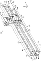
图4是容器传送设备的透视图,所述容器传送装置成实施本发明多个方面的容器分配器的形式。Figure 4 is a perspective view of a container transfer apparatus in the form of a container dispenser embodying aspects of the present invention.
图5是容器分配器的、与图4中所示相反的一侧的透视图。Figure 5 is a perspective view of the opposite side of the container dispenser from that shown in Figure 4 .
图6是容器分配器的容器支架组件的局部放大透视图。Figure 6 is an enlarged partial perspective view of the container holder assembly of the container dispenser.
图7是容器分配器的轨道组件的近端的局部放大透视图,其显示了具有皮带轮和弹簧的皮带张紧器。7 is an enlarged fragmentary perspective view of the proximal end of the track assembly of the container dispenser showing the belt tensioner with pulleys and springs.
图8是容器分配器的轨道组件的远端的局部放大透视图,其显示了原位传感器和支架平移皮带驱动轮。8 is an enlarged fragmentary perspective view of the distal end of the track assembly of the container dispenser showing the home position sensor and carriage translation belt drive pulley.
图9是容器支架组件的局部放大透视图,其显示了容器分配头以及支架组件滑架的一部分。Figure 9 is an enlarged fragmentary perspective view of the container holder assembly showing the container dispensing head and a portion of the holder assembly carriage.
图10是容器支架组件的支架组件滑架的Z轴线驱动系统的透视图。10 is a perspective view of the Z-axis drive system of the carriage assembly carriage of the vessel carriage assembly.
图11是图10的Z轴线驱动系统沿线11-11的局部横截面透视图。11 is a partial cross-sectional perspective view of the Z-axis drive system of FIG. 10 taken along line 11-11.
图12是容器支架组件的支架组件滑架的支架旋转系统(Θ驱动系统)的局部透视图。12 is a partial perspective view of the rack rotation system (Θ drive system) of the rack assembly carriage of the container rack assembly.
图13是支架旋转系统的一部分的局部放大透视图。Figure 13 is an enlarged fragmentary perspective view of a portion of the stent rotation system.
图14是容器分配头和钩致动器系统处于延伸位置的透视图。Figure 14 is a perspective view of the container dispensing head and hook actuator system in an extended position.
图15是容器分配头和钩致动器系统处于缩回位置以及在分配头内部的多容器装置的透视图。Figure 15 is a perspective view of the container dispensing head and hook actuator system in the retracted position and the multi-container device inside the dispensing head.
图16是容器分配头在从与图14和15中所示相反的一侧看时的透视图。Figure 16 is a perspective view of the container dispensing head as viewed from the opposite side to that shown in Figures 14 and 15.
图17是分配头沿图16中的线17-17的局部横截面透视图。17 is a partial cross-sectional perspective view of the dispensing head taken along line 17-17 in FIG. 16. FIG.
图18是容器分配头的端视图。Figure 18 is an end view of a container dispensing head.
图19是恒温器和容器输送机构的局部透视图,所述容器输送机构适于将反应容器置于恒温器内和从所述恒温器中取出反应容器。Figure 19 is a partial perspective view of an incubator and a vessel transport mechanism adapted to place and remove reaction vessels in and out of the incubator.
图20是容器分配器的控制结构的示意方框图。Figure 20 is a schematic block diagram of the control structure of the container dispenser.
图21是表示处理的步骤的流程图,容器分配器通过这些步骤而自动确定容器传送位置相对于仪器的各模块的坐标。Figure 21 is a flow chart showing the steps of the process by which the container dispenser automatically determines the coordinates of the container transfer location relative to the various modules of the instrument.
具体实施方式 Detailed ways
概述overview
在图1中,可以实施本发明方法和设备的分析器以平面图示意表示,并由附图标记100表示。分配器100包括构造成接收一个或多个反应容器(后面将更详细介绍)的多种模块,多步骤分析处理(例如核酸测试(NAT),或者其它化学、生物化学或生物处理)中的一个或多个步骤在各反应容器中进行。分析器100的模块构成容器接收结构,所述容器接收结构构造成接收和保持一个或多个反应容器。本发明实现了用于在分析器100的多种模块之间传送反应容器以及用于将反应容器插入模块中和从模块中取出反应容器的方法和设备。In FIG. 1 , an analyzer in which the method and apparatus of the present invention may be implemented is schematically shown in plan and denoted by
在一个实施例中,可以在其中实施本发明的示例分析器可以包括容器输入模块102,所述容器输入模块102包括用于在容器用于执行化学、生物或者其它多步骤分析处理之前接收和保持一个或多个空反应容器的结构。容器输入模块102可以包括保持多个容器的抽屉,并可以包括用于使得容器例如一次一个地进入容器拾取位置的容器供给设备。In one embodiment, an example analyzer in which the present invention may be practiced may include a
分析器100还可以包括装载站104、106、108,这些装载站104、106、108构造成接收反应容器,且可以在这些装载站104、106、108内将一种或多种材料添加给容器,所述材料包括试样材料和多种反应剂。在分析器100包括用于进行NAT的平台的实施例中,反应剂可以包括目标捕获剂、核酸放大剂和核酸检测剂。The
分析器100还可以包括温度斜升(ramping)站110,所述温度斜升站110构造成将一个或多个反应容器保持在这样的环境中,所述环境保持在比周围环境温度更高的温度,以便升高容器的内容物的温度。分析器100还可以包括一个或多个恒温器。所示分析器100包括三个恒温器112、114、116,这些恒温器112、114、116各自构造成接收多个反应容器和将这些容器保持在升高温度的环境中。
并且,在分析器100包括用于进行NAT的平台的实施例中,分析器可以包括试样处理模块,例如磁分离洗涤站118、120,其适于使得粘附磁性响应目标捕获材料上的、感兴趣的分析物与容器的剩余内容物分离或隔离。分析器100还可以包括冷却模块122,其适于接收一个或多个反应容器,并将容器保持在比周围环境温度更低的温度中,以便降低容器的内容物的温度。最后,分析器100可以包括检测器模块124,所述检测器模块124适于接收反应容器,并检测由反应容器的内容物发出的信号(例如光学信号)。在一个实施例中,检测器模块124可以包括光度计,其用于检测由容器或荧光计的内容物发出的光信号以检测荧光发射。Also, in embodiments where the
分析器100还包括容器传送设备,在所示实施例中,所述容器传送设备包括容器分配器300,所述容器分配器300实现本发明的多个方面。分析器100的模块中的每个模块包括容器传送入口,容器通过所述容器传送入口而插入各模块中或从各模块中取出。各模块可以包括或不包括可打开的门,所述门覆盖其容器入口。容器分配器300构造成使得容器在多种模块之间运动、从模块取回容器以及将容器布置在模块内。更具体地说,容器分配器300包括容器分配头312,所述容器分配头312构造成沿输送轨道组件458而沿X方向运动、沿Θ方向旋转以及使得容器沿R方向运动进入和运动离开容器分配头312和分析器100的模块中的一个模块。The
在操作中,容器分配头312沿输送轨道组件458沿X方向运动至相对于模块中一个模块的输送位置。然后,分配头沿Θ方向旋转,以便使得分配头相对于模块的容器传送入口布置成容器传送方位。容器运动机构相对于分配头沿R方向运动,以便使得容器从分配头运动进入模块,或者将容器从模块取回至分配头。如后面更详细所述,容器分配器还包括用于进行分配头的竖直(Z轴线,垂直于图1的页面)位置调节的装置,以便适应各种模块的容器传送入口由于例如制造和安装公差而引起的竖直位置变化。还有,如后面更详细所述,容器分配器300包括“自教导”系统,用于自动识别对于各模块的容器传送入口的正确X、Z和R传送位置。最后,容器分配器300可以包括结构元件和相关联的控制逻辑电路,用于在将反应容器插入模块之前或将反应容器从模块中取出之前打开覆盖容器传送入口的门。In operation, the
多容器装置multi-vessel device
如图2中所示,成多容器装置(“MRD”)160(所述多容器装置160能够与本发明结合使用)形式的反应容器包括多个单独的反应容器162,在所示实施例中为5个。其它类型的容器装置内部与本发明结合使用,包括包含单个单独的反应容器的装置。在所示实施例中,反应容器162成具有开口顶端和关闭底端的柱形管形式,并通过联接肋结构164而相互联接,所述联接肋结构164限定了沿MRD 160的各侧纵向延伸的朝下肩部。在MRD 160的所示实施例中,全部反应容器162的尺寸和形状基本相同。在其它实施例中,MRD可以包括不同尺寸、形状和类型的反应容器,并能够构造成用于本发明(例如微滴定度板)。As shown in Figure 2, a reaction vessel in the form of a multi-vessel device ("MRD") 160 (which can be used in conjunction with the present invention) includes a plurality of
在一个实施例中,MRD160或其它容器由注射模制的聚丙烯形成,例如由Montell Polyolefins,Wilmington,Delaware出售,产品号PD701NW,或者由Huntsman出售,产品号为P5M6K-048。In one embodiment, the
弓形屏蔽结构169布置在MRD 160的一端处。MRD操纵结构166从屏蔽结构169伸出。操纵结构适于与容器分配器300接合,用于使得MRD160在分析器100的不同位置之间运动。MRD操纵结构166包括横向延伸板168,所述横向延伸板168从屏蔽结构169伸出,并具有在板168的相对端部上的竖直延伸件167。角撑板壁165在屏蔽结构169和竖直件167之间从横向板168向下延伸。An
如图3中所示,屏蔽结构169和竖直件167具有彼此相对的凸形表面。MRD 160可以通过使得接合部件(例如钩)横向(沿图2中的方向“A”)运动至在屏蔽结构169和竖直件167之间的空间内而与分配器300接合。屏蔽结构169和竖直件167的凸形表面为进行横向相对运动的接合部件提供了进入空间内的更宽的进入点。As shown in FIG. 3 , the
具有扁平标签接收表面175的标签接收结构174布置在MRD 160的、与屏蔽结构169和MRD操纵结构166相反的端部上。人和/或机器可读的标签(例如可扫描条形码)能够布置在所述表面175上,以便在MRD 160上提供识别和/或仪器信息。MRD 160还可以包括在各反应容器162的开口嘴附近的尖端(tiplet)保持结构176。各尖端保持结构176提供了柱形孔,适于布置在抽吸管(未示出)端部上的导管(例如接触限制尖端170)接收于所述柱形孔内。各保持结构176构成和布置成以这样的方式摩擦地接收尖端170,即当MRD 160倒转时防止尖端170从保持结构176向外跌落,但是当与吸管接合时能够将尖端170从保持结构176中取出。关于MRD 160的这种实施例的进一步详细说明可以在美国专利No.6,086,827中找到。A
容器分配器container allocator
如图4-6中所示,成容器分配器300形式的容器传送设备包括容器支架组件310,所述容器支架组件310在X平移系统(后面将介绍)的动力作用下沿“X”方向沿输送轨道组件458平移。容器支架组件310包括容器分配头312,所述容器分配头312构造成承载支承在支架组件滑架400上的反应容器(例如MRD 160),所述支架组件滑架400构成和布置成实现分配头312的Z轴线平移和Θ旋转,如后面所述。在所示实施例中,轨道组件458为线性(即直线形)和基本水平,但是可以理解的是,具有非线性(即至少局部弯曲)和/或非水平(即轨道组件的至少一部分倾斜或竖直)的轨道组件的容器分配器可包括在本发明的多个方面,且本发明的范围包括这样的容器分配器。As shown in FIGS. 4-6, a container transfer device in the form of a
在所示实施例中,轨道组件458包括大致“L”形槽道460,所述槽道460包括基部部分462(在所示实施例中定向成基本水平)以及从水平基部462的一个边缘以竖直方式延伸的竖直背衬464(在所示实施例中定向成基本竖直)。加强凸缘474从基部部分462的、与竖直背衬464相反的边缘竖直延伸,且加强凸缘472从竖直背衬464的上边缘横向延伸。导轨480安装在竖直背衬464上,并相对于基部部分462以平行方位延伸。索缆引导轨道486安装在基部部分462上。In the illustrated embodiment, the
X平移系统500包括驱动或传动皮带504,所述皮带504环套在从动皮带轮506和惰轮516上,所述从动皮带轮506布置在竖直背衬464的一侧并在槽道460的远端476处,所述惰轮516布置在竖直背衬464的相同侧并在槽道460的近端478处。从动皮带轮506与安装在竖直背衬464的相对侧的支架平移电机502操作地联接(见图5)。支架平移电机502优选是步进电机,具有附接在与从动皮带轮506联接的驱动轴上的光学编码器。合适的电机包括Nanotec型号no.ST5918L6404-KSTR-E1,合适的编码器包括HEDSS型号no.HKT2204-702C-200B-5E。驱动皮带504优选是具有5mm模块(T5)切割段的Kevlar皮带。The
如图5中所示,驱动皮带504通过托架508而附接在支架组件310上,所述托架508将皮带504固定在滑架400的一侧上。在竖直背衬464中的进入开口466提供了通向托架508的进口,并方便将支架组件310附接在驱动皮带504上。As shown in FIG. 5 , the
参考图7(图7显示了轨道组件458的近端478的局部透视图),驱动皮带504优选是装备有皮带张紧器510。皮带张紧器510包括滑动皮带轮安装件512和弹簧514,惰轮516安装在所述滑动皮带轮安装件512上。弹簧514布置在形成于槽道460的竖直背衬464中的开口468内,并在开口468的边缘和滑动皮带轮安装件512的、布置在开口468内或附近的部分之间压缩。滑动皮带轮安装件512包括横向销518,所述横向销518伸入形成于竖直背衬464中的纵向延伸狭槽470内。螺钉520穿过滑动皮带轮安装件468延伸,并伸入形成于竖直背衬464中的狭槽开口内。在容器分配器300的装配过程中,驱动皮带504在输送轨道组件458的远端476处布置在支架平移电机502的从动皮带轮506上。滑动皮带轮安装件512和惰轮516逆着弹簧514推向从动皮带轮506(只要狭槽470的长度允许,销518在所述狭槽470中延伸),且滑动皮带轮安装件512通过螺钉520来固定,以便使得驱动皮带504能够在输送轨道组件458的近端478处布置在惰轮516上。然后,皮带张紧器510的螺钉520松开,通过弹簧514而保持驱动皮带504的张力,所述弹簧514沿离开从动皮带轮506的方向推压滑动皮带轮安装件512和皮带轮516。然后,在弹簧514使得驱动皮带504合适拉伸之后,皮带轮516的位置通过螺钉520来固定。Referring to FIG. 7 (which shows a partial perspective view of the
支架组件310的分配头312由支架组件滑架400沿输送轨道组件458承载。支架组件滑架400与导轨480接合,并沿输送轨道组件458平移。橡胶缓冲器482、484可以布置在导轨480的相对端处,以便吸收与滑架400的接触。支架组件滑架400沿导轨480的运动通过驱动皮带504而实现。当支架平移电机502使得从动皮带轮以逆时针方式旋转时,支架组件310沿第一X方向(朝向所示实施例的左侧)朝着输送轨道组件458的近端478运动。类似地,当支架平移电机502使得从动皮带轮506以顺时针方式旋转时,支架组件310沿第二X方向(朝向所示实施例的右侧)朝着输送轨道组件458的远端476平移。
在一个实施例中,支架组件310具有750mm的线性行程。从动皮带轮506的直径优选是21.45mm,在全步进模式中,支架平移电机502提供0.337mm/步的分辨率(resolution)。电机502的编码器提供200数/转(A-B信号)的分辨率,从而形成800数/转的四倍分辨率。In one embodiment,
如图5和8中所示(图中显示了轨道组件458的远端476的局部透视图),用于支架平移电机502的X驱动印刷电路板(“PCB”)522安装在邻近支架平移电机502的槽道460的竖直背衬464上。X驱动PCB 522通过柔性电缆524而与支架组件滑架400电子联接。当支架组件滑架400沿输送轨道组件458平移至各个位置时,电缆引导件486引导柔性电缆524。应变释放器526、528分别将柔性电缆524固定在支架组件滑架400上和输送轨道组件458上。As shown in FIGS. 5 and 8 (showing partial perspective views of the
如图8中所示,安装在X驱动PCB 522上的“原位”传感器530检测支架组件310何时处于输送轨道组件458的远端476。传感器530优选是具有狭槽的光学传感器,它在从支架组件滑架400凸出的结构元件(例如杆或标记)中断传感器时“跳闸”。合适的传感器包括OPTEK型号no.OPB900W55。As shown in FIG. 8 , a "home position"
当通过使得附接在支架组件滑架400上的驱动皮带504旋转的电机502和从动皮带轮506来使支架组件310和分配头312沿轨道组件458进行X轴线平移时,通过装于支架组件滑架400内的Z轴线驱动系统402来使得分配头312相对于轨道组件458横向或Z轴线平移。参考图10和11(图中显示了装于支架组件滑架400中的Z轴线驱动系统402),Z轴线驱动系统402包括:Z驱动步进电机404,所述Z驱动步进电机404安装在电机安装件410上;以及升高块412,所述升高块412通过与滚珠螺母408(所述球螺母408附接在升高块412的箱腔室部分418的底部面板416上)接合的滚珠丝杠406而与电机404操作地联接。合适的电机包括Nanotec型号no.ST4118M1404-B。分配头312支承在升高块412上,并在电机404的动力作用下经由与滚珠螺母408接合的滚珠丝杆406的旋转而向上或向下横向平移。升高块412通过线性引导件424而支承为用于相对轨道组件458横向(在所示实施例中为竖直)运动,所述线性引导件424包括:导轨425,所述导轨425附接在升高块412的箱腔室部分414的竖直外壁418上;以及线性轴承427(例如IGUS线性引导轴承),所述线性轴承427附接在滑架400的滑架壳体壁401的一部分上。When the
如图11中所示,Z“原位”传感器428安装在Z驱动PCB 426上,并发送升高块412的最低位置的信号。Z原位传感器428优选是具有狭槽的光学传感器,它在从升高块412的箱腔室部分414凸出的原位标记419中断传感器428时“跳闸”。合适的传感器包括Sharp型号no.GP1S94。角形编码器包括在Z驱动印刷电路板426上的两个具有狭槽的光学传感器(未示出)以及与电机的轴一起旋转的具有狭槽的盘432。合适的传感器包括Sharp型号no.GP1S94。编码器的理论分辨率优选是0.04mm。As shown in FIG. 11 , a Z "home position"
分配头312的旋转通过Θ驱动系统来进行,所述Θ驱动系统也位于支架组件滑架400内,并在图9、12和13中总体由附图标记440表示。Θ驱动系统包括:支架旋转电机442,所述支架旋转电机442安装在升高块412的电机安装部分420上;平台齿轮446,分配头312承载在所述平台齿轮446上,且所述平台齿轮446可旋转地安装在轴(未示出)上,所述轴支承在压入升高块412的轴承块部分422内的轴承449(也见图11)内;以及驱动齿轮444,所述驱动齿轮444安装在电机442的输出轴上。轴承449和支承在所述轴承449内的轴限定了与轴承449的纵向轴线相对应的、分配头312的旋转轴线。合适的电机包括Nanotec型号no.ST4118S1404-KSTR-E1。旋转编码器441与电机442联接。合适的编码器包括HEDSS型号no.HKT2204-702C-200B-5E。驱动齿轮444例如通过匹配齿轮齿而与平台齿轮446操作地接合。由图12和13可知,驱动齿轮444通过电机442进行的旋转使得平台齿轮446进行相应旋转,这又使得分配头312沿Θ方向旋转。Rotation of dispense
在所示实施例中,轨道组件458基本水平,且由轴承449的纵向轴线确定的旋转轴线基本竖直和与轨道组件458成直角垂直。然而可以理解的是,可在不一定竖直或与轨道组件458垂直的旋转轴线上旋转的分配头可包括在本发明的多个方面,且本发明的范围包括这样的分配头。In the illustrated embodiment,
分配头312操作地联接成通过柔性电缆452而与滑架400电子通信,所述柔性电缆452在一端处与附接在滑架400上的Z驱动PCB 426联接,在它的相对端处与附接在分配头312上的钩延伸PCB 362联接(见图9)。应变释放器454和456分别将柔性电缆452固定在支架组件滑架400上和分配头312上。如图12和13中所示,电缆452的中间部分松弛地环绕平台齿轮446的旋转轴线盘绕,以便适应分配头312的旋转。
如图9和13中所示,分配头312的旋转位置通过Θ原位传感器450(优选是具有狭槽的光学传感器)来确定。合适的传感器包括OPTHK型号no.OPB 900W55。孔448穿过平台齿轮446而形成。当平台齿轮446旋转至原位位置时,传感器450遇到孔448,从而使得传感器450跳闸(通过接通传感器射束),以便指示平台齿轮446的原位旋转位置,从而指示分配头312的原位旋转位置。在一个实施例中,分配器头312的原位位置对应于分配头312与轨道组件458的纵向轴线(X)对齐,且是当支架组件310沿轨道组件458平移时分配器头312的优选方位。As shown in Figures 9 and 13, the rotational position of the dispense
用于容器162的分配头312优选旋转280°,以便到达使得分析器模块的容器传送入口位于自动分析器上的任意方向。分配头的旋转角度通过机械止动器而限制为280°,例如在图12中通过齿轮446的底部凸出的螺钉445,所述螺钉445将撞上块412,以便限制旋转。The dispensing
支架旋转电机442优选是步进电机,具有附接在电机轴上的旋转编码器441。旋转编码器的分辨率优选是200数/转(A-B信号),从而形成800数/转的四倍分辨率。在平台齿轮446和驱动齿轮444之间的齿轮比优选是8比1。在全步进模式中,驱动系统Θ的角度步进优选是0.225°。电机442优选是安装在形成于升高块412的电机安装部分420中的狭槽内,并在制造过程中推向平台齿轮446,以避免松弛。The
分配头312的细节如图14-18中所示。分配头312包括分配框架314,所述分配框架314附接在Θ驱动系统440的平台齿轮446上。侧部面板315附接在分配头框架314的一侧。侧部面板315可以是透明的,以使得可以看见分配头312的内部。分配头312还包括容器钩318,所述容器钩318构造成与MRD 160的操纵结构166接合。不同于钩的、用于与容器接合和使得接合的容器能够进行物理操纵的装置也包含在本发明的范围内。Details of dispense
钩致动器系统316使得容器钩318在延伸位置(如图14中所示)和缩回位置(如图15中所示)之间进行线性平移(沿R方向)。钩致动器系统316包括钩滑架320,容器钩318安装在所述钩滑架320上。驱动皮带344通过在322处所示的螺钉和托架而安装在钩滑架320上。驱动皮带344承载在驱动轮334和惰轮336、338、340、342上。惰轮340和342附接在固定的惰轮托架358上,惰轮338附接在面板315外部的门接合托架360的上部部分上。The
门接合托架360可以用于打开覆盖分配器100的模块的容器传送入口的门。可以是枢轴转动、滑动或旋转门的所述门包括悬在门的一部分上的臂或其它凸起。分配头312定位成通过门接合托架360的底端而与臂接触,且分配头312的稍微X和/或Θ运动将使得门从关闭位置运动至打开位置。门优选是弹簧偏压至关闭位置,这样,当臂释放与门接合托架360的接触时,门将弹回至关闭位置。The
驱动轮334安装在驱动电机332的输出轴上,所述驱动电机332优选是步进电机。合适的电机包括Nanotec型号no.ST4118M1404-B。旋转编码器333附接在驱动电机332上。合适的编码器包括HEDSS型号no.HKT2204-702C-200B-5E。驱动轮334优选是具有9.55mm的直径,从而导致每电机全步进0.15mm的分辨率。编码器333具有200数/转(A-B信号)的分辨率,从而形成800数/转的四倍分辨率。The
钩致动器系统316优选包括用于在皮带344中保持合适张力的皮带张紧器346。皮带张紧器346包括枢轴转动惰轮托架348,惰轮336附接在所述枢轴转动惰轮托架348上,且所述枢轴转动惰轮托架348通过枢轴螺钉352而可枢轴转动地附接在侧部面板315上。狭槽350形成于枢轴转动惰轮托架348的端部中,且位置锁定螺钉354穿过狭槽350伸入侧部面板315中。弹簧356布置在枢轴转动惰轮托架348的一部分和固定惰轮托架358之间。在皮带344中的张力能够通过松开位置锁定螺钉354来调节,从而使得弹簧356能够使枢轴转动惰轮托架348枢轴转动,并因此向上推压惰轮336,以便在驱动皮带344中产生合适的张力。当在驱动皮带344中获得合适的张力时,位置锁定螺钉354能够再重新拧紧。
钩滑架320包括导轨槽道324,所述导轨槽道沿附接在分配头框架314的上部部分上的钩滑架导轨330平移。容器钩318附接在布置于导轨槽道324和钩318之间的绝缘安装件326上,以便使得钩318与分配头312电绝缘,从而方便电容感测钩318与分析器100的其它结构元件的接触,如后面所述。The
如图18中所示,分配头312优选是包括MRD支承壁架372,用于支承由MRD 160的联接结构164限定的肩部。还有,MRD引导件370布置在分配头框架314的内部,以便防止MRD在分配头312内部升高。As shown in FIG. 18, the dispensing
钩延伸部分PCB 362附接在分配头312的一侧上(见图17)。钩原位传感器364(优选是有狭槽的光学传感器)附接在钩延伸部分PCB 362上。合适的传感器包括Sharp型号no.GP1S94。钩传感器364表示当钩处于缩回或“原位”位置时,从绝缘安装件326伸出的传感器标记328何时伸入具有狭槽的光学传感器364内。容器钩318和钩滑架320操作地联接成通过柔性电缆366而与分配头312的其余部分电子通信,所述柔性电缆366在一端处附接在钩滑架320上,在相对端处附接在钩延伸部分PCB 362上。应变释放器368和369可以分别用于将柔性电缆366固定在分配头框架314和钩滑架320上。The
本发明的自动分析器包括传送位置定位系统和方法,适于对于构成分析器100的模块的各容器接收结构自动确定分配头312相对于容器传送入口的传送位置的定位,以便使得分配头312能够在分配头和模块之间传送容器或一组容器,例如MRD 160。The automatic analyzer of the present invention includes a delivery position positioning system and method adapted to automatically determine the location of the delivery position of the dispensing
在一个实施例中,传送位置定位方法包括以下步骤:使得分配头312沿输送轨道458运动至容器接收结构中一个容器接收结构(例如分析器模块)的近似位置,并使得分配头312停止在所述近似位置;以及使得分配头312(或者它的一部分,例如钩318)相对于容器接收结构沿两个或更多方向运动,直到与分配头312相关联的位置定位器元件和与容器接收机构相关联的位置定位器元件接合。与分配头312相关联的位置定位器元件和与容器接收机构相关联的位置定位器元件的接合表示分配头312相对于容器接收机构处于传送位置(或者,分配头处于离传送位置已知距离和方向的位置处),以便使得分配头312能够在分配头312和容器接收机构之间传送容器。储存用于所述容器接收机构的传送位置坐标,且对于各容器接收机构重复这些步骤。通过取回与容器接收机构相关联的储存传送位置坐标和使得分配头运动至取回的传送位置,分配头312能够在以后相对于各容器接收机构定位成使得分配头312能够在分配头和容器接收机构之间传送容器。In one embodiment, the transfer position positioning method includes the steps of: moving the dispensing
与本发明的分配头312相关联的位置定位器元件优选是成钩318的形式,所述钩318与电容检测系统联接,用于检测钩318与其它结构接触。与容器接收机构或分析器模块相关联的位置定位器元件优选是成凸起(例如金属销)的形式,所述凸起在相对于用于模块的传送位置在已知位置处从所述模块伸出。其它位置定位器元件可以包括霍尔效应传感器或光学传感器(例如有狭槽的光学传感器或反射传感器)。其它基于光学的位置定位器包括使用图像处理来找到基准的照相机。位置定位器元件还可以相对于容器传送入口门的打开臂位于已知位置,这样,模块的位置定位器元件的定位也限定了分配头312的位置,以便使得门接合托架360能够与模块的门打开臂接合。The position locator element associated with the dispensing
图19显示了分配头312的、使得容器钩318伸入恒温器114的门组件214的容器入口204内的部分。门组件214包括驱动杆220,所述驱动杆220从可滑动地布置在门框架224中的门216上伸出,以便当处于关闭位置时覆盖入口204。分配头312的门接合托架360与驱动杆220接合,以便将门216推向打开位置。当门216处于打开位置时,容器钩318能够穿过容器开口204伸出,以便使得MRD 160插入在恒温器114中的容器支架242(例如圆盘传送器)内,或者使得MRD 160从容器支架242退回。FIG. 19 shows the portion of the dispensing
恒温器114还包括在容器入口204附近从门框架224凸出的定位器销210。相对于容器入口204位于已知位置的销210用作用于恒温器114的位置定位器元件。通过确定和储存X、Z、Θ和R坐标(容器钩318在这些X、Z、Θ和R坐标处与销210接触),当容器需要布置在恒温器114中或者从该恒温器取出时,这些坐标能够重新调用,以便合适地定位和定向容器支架组件310和分配头312。The
应当知道,图19中所示的门接合托架360定向成与其它图(例如图18)中所示的门接合托架360不同。在图19中,门接合托架360从分配头312的右手侧向外伸出(当沿容器钩延伸部分的方向看时,如图19中所示),用于通过向右推动它而打开门216,如图19中所示。另一方面,在图18中,门接合托架360从分配头312的左手侧向外伸出(当沿容器钩延伸部分的方向看时,它与图18中所示观察方向相反),用于通过向左推动它而打开门。因此,分配头312能够构造成通过向左或向右推动而打开模块门(根据门接合托架360的方位)。门接合托架还能够构造成在分配头312的左手侧和右手侧都伸出,这样,头312能够选择地向左或向右推动门,因此,并不是所有的模块门都需要构造成通过沿相同方向滑动而打开。在其它实施例中,门可以通过不同于横向运动而打开。例如,门能够通过枢轴转动、铰接运动、向上或向下竖直运动、或者通过旋转或回转运动而打开。分配头312能够构造成与门接合,并进行合适的相对运动以便打开门。It should be appreciated that the
图20是示意表示用于容器分配器300的控制结构的方框图。控制结构包括控制器550,所述控制器550与X平移系统500、Z轴线驱动系统402、Θ驱动系统440和钩致动器系统316的各方面通信并且控制X平移系统500、Z轴线驱动系统402、Θ驱动系统440和钩致动器系统316的各方面。FIG. 20 is a block diagram schematically showing a control structure for the
控制器550包括计算机系统,用于执行实施本发明方法和系统的软件。控制器550包括至少一个处理器,例如计算机,并包括数据储存存储器,所述数据储存存储器可以包括随机存储器(RAM)、只读存储器(ROM)和本领域技术人员已知的其它类型存储器。控制器550还可以包括附加存储器,例如包括硬盘驱动器和/或可拆卸储存装置,例如磁带驱动器、光盘驱动器、USB槽、记忆卡界面等。这里使用的存储器装置和储存单元可以包括本领域普通技术人员已知或以后发展的、用于持久和/或暂时储存电子数据的任意储存介质。这些数据可以储存在数据库中的储存介质中,所述数据可以包括本领域普通技术人员已知或以后发展的任意数据结构和格式,例如关系数据库、对象数据库、平面文件、列表等,或者它们的一些组合。Controller 550 includes a computer system for executing software implementing the methods and systems of the present invention. Controller 550 includes at least one processor, such as a computer, and includes data storage memory, which may include random access memory (RAM), read only memory (ROM), and other types of memory known to those skilled in the art. Controller 550 may also include additional storage, including, for example, a hard drive and/or removable storage devices, such as tape drives, optical drives, USB slots, memory card interfaces, and the like. Memory devices and storage units as used herein may include any storage media known or later developed by those of ordinary skill in the art for the persistent and/or temporary storage of electronic data. These data may be stored in the storage medium in the database, and the data may include any data structure and format known to those of ordinary skill in the art or later developed, such as relational databases, object databases, flat files, lists, etc., or their some combinations.
在可选实施例中,一些或全部存储器可以包括用于使得计算机程序或其它指令能够装入计算机系统内的其它类似装置。这些装置例如能够包括可拆卸的储存单元以及界面。它们的实例可以包括记忆棒和记忆棒界面、安全数据卡和界面、以及使得软件和数据能够传送给控制器550的其它便携式介质和界面。In alternative embodiments, some or all of the memory may include other similar means for enabling computer programs or other instructions to be loaded into the computer system. These means can include, for example, a detachable storage unit and an interface. Examples of these may include memory sticks and memory stick interfaces, secure data cards and interfaces, and other portable media and interfaces that enable software and data to be transferred to controller 550 .
控制器550的计算机系统还可以包括通信界面,所述通信界面使得信息(例如软件、数据等)能够在控制器550和外部装置之间传送。通信界面的实例能够包括调制解调器、网络界面(例如以太网卡)、通信口、PCMCIA槽和卡、USB口、火线口等。通过通信界面传送的信息成信号的形式,所述信号能够是电子、电磁、光学或者能够由通信界面接收的其它信号。The computer system of the controller 550 may also include a communication interface that enables information (eg, software, data, etc.) to be transferred between the controller 550 and external devices. Examples of communication interfaces can include modems, network interfaces (eg, Ethernet cards), communication ports, PCMCIA slots and cards, USB ports, FireWire ports, and the like. Information communicated through the communication interface is in the form of signals, which can be electronic, electromagnetic, optical, or other signals capable of being received by the communication interface.
控制器550的计算机系统还能够包括一个或多个输入装置,例如接触屏、输入笔、键盘、鼠标或其它指示装置、麦克风等。多种输出装置也可以包含在计算机系统中,包括注射器灯、显示器、打印机和音频扬声器。The computer system of the controller 550 can also include one or more input devices, such as a touch screen, a stylus, a keyboard, a mouse or other pointing device, a microphone, and the like. Various output devices may also be included in the computer system, including syringe lights, monitors, printers, and audio speakers.
在本文中,术语例如“计算机程序介质”、“计算机可读介质”、“压缩机可用介质”等用于总体表示介质,例如可拆卸的储存单元、安装在硬盘驱动器中的硬盘、或者用于向控制器550提供软件和数据的信号或其它装置。In this document, terms such as "computer program medium", "computer-readable medium", "compressor-usable medium", etc. are used to refer generally to media such as removable storage units, Signals or other means to provide software and data to controller 550 .
计算机程序(也称为计算机控制逻辑电路)储存在控制器550的存储器的一个或多个部分中。计算机程序还能够通过通信界面来接收。这些计算机程序在执行时使得控制器550的计算机系统能够执行本发明的各方面。A computer program (also referred to as computer control logic) is stored in one or more portions of the memory of the controller 550 . A computer program can also be received through a communication interface. These computer programs, when executed, enable the computer system of the controller 550 to perform aspects of the present invention.
在使用软件来执行本发明方面的实施例中,软件能够储存在计算机程序产品中,并使用可拆卸的储存驱动器、硬盘驱动器、界面和/或通信界面而装入控制器550的计算机系统中。控制逻辑电路(软件)在由控制器550的处理器执行时使得处理器能够通过上述系统、装置、传感器、编码器等来执行本发明的多个功能方面,如本文中所述。操作系统可以执行基本任务,例如认识来自输入装置的输入、向输出装置发送输出、管理文件和系统资源、以及管理在计算机系统上运行计算机程序的多种处理。In embodiments where software is used to implement aspects of the invention, the software can be stored in a computer program product and loaded into the computer system of controller 550 using a removable storage drive, hard drive, interface and/or communication interface. The control logic (software) when executed by the processor of the controller 550 enables the processor to perform the various functional aspects of the invention through the systems, devices, sensors, encoders, etc. described above, as described herein. An operating system can perform basic tasks such as recognizing input from input devices, sending output to output devices, managing files and system resources, and managing the various processes of running computer programs on the computer system.
控制器550可以包括专用于容器分配器的独立系统,或者控制器550的一个或多个组件(例如处理器、存储器、界面、输入/输出装置等)可以是除了容器分配器300之外还控制分析器100的一个或多个模块的总控制器的共用部分。Controller 550 may comprise a separate system dedicated to the container dispenser, or one or more components of controller 550 (e.g., processor, memory, interface, input/output devices, etc.) A common part of the overall controller of one or more modules of the
如图20中示意所示,对于X平移系统500,控制器550从与电机502联接的光学编码器503和从原位传感器530接收信号,并向电机502发送指令信号。对于Z轴线驱动系统402,控制器550从与滚珠丝杆406联接的编码器405(例如有狭槽的盘432)和从原位传感器428接收信号,并向电机404发送指令信号。对于Θ驱动系统440,控制器550从与电机442联接的编码器441和从原位传感器450接收信号,并向电机442发送指令信号。且对于钩致动器系统316,控制器550从与电机332联接的编码器333、从原位传感器364和从电容钩318接收信号,并向电机332发送指令信号。As schematically shown in FIG. 20 , for the
用于自动检测容器传送位置相对于分析器100的模块的位置坐标的方法由图21中的流程图600来表示。所示的一些或全部处理能够在计算机指令中实施,所述计算机指令作为软件而储存在控制器550可存取的存储器中。A method for automatically detecting the position coordinates of the container delivery position relative to the modules of the
在步骤602中,容器支架组件310从X、Z、Θ、R=0的位置开始,如通过由X平移系统500的原位传感器530、Z轴线驱动系统402的原位传感器428、Θ驱动系统440的原位传感器450和钩致动器系统316的原位传感器364产生的信号而与控制器550通信。In
在步骤604中,通过控制器的处理器而从控制器550的存储器中取回分析器模块中的一个分析器模块的近似X坐标位置,且控制器550向X平移系统500的电机502发送指令信号,以便使得支架组件310沿输送轨道组件458沿X方向运动至分析器模块的近似X坐标。支架组件310处于近似X坐标能够通过发送给电机502的指令信号(例如运动特定数目的步进)和/或通过由编码器503产生的信号来确认。In
在步骤606中,控制器550命令Θ驱动系统440的电机442使得分配头312旋转至大约90度的方位,以使得分配头312的容器开口朝向模块。支架组件310处于所需的的旋转方位能够通过发送给电机442的指令信号(例如运动特定数目的步进)和/或通过由编码器441产生的信号来确认。In
在步骤608中,控制器550命令Z轴线驱动系统402的电机440使得分配头312沿+Z轴线方向向上运动特定距离(例如5mm至Z=+5mm的绝对位置)。支架组件310沿Z轴线运动合适距离能够通过发送给电机404的指令信号(例如运动特定数目的步进)和/或通过由编码器405产生的信号来确认。In
在步骤610中,控制器550命令钩致动器系统316的电机332使得钩318伸出至位置定位器元件(例如在相对于用于模块的容器传送位置在已知位置处从模块伸出的销或其它凸起)的理论位置。所述理论位置能够通过使得钩318朝着模块运动特定距离(例如2mm)而实现,或者当理论位置对于不同模块明显变化时,理论位置的坐标能够储存在控制器的存储器中,并在需要时由控制器550的处理器取回。钩318延伸至所需的位置能够通过发送给电机332的指令信号(例如运动特定数目的步进)和/或通过由编码器333产生的信号来确认。In
在步骤612中,控制器550命令X平移系统500的电机502使得容器支架组件310一步步地沿X轴线朝着位置定位器元件的预期位置运动,直到钩318与位置定位器元件接触,如通过电容感测来检测和与控制器550通信。控制器550命令电机502使得X平移停止,且在步骤614中,接触的X坐标(如通过由X平移系统500的编码器503产生的信号来确定)储存在控制器550的存储器中。In
在步骤616中,控制器550命令钩致动器系统316的电机332使得钩318缩回至分配头312内。In
在步骤618中,控制器550命令Z轴线驱动系统402的电机404使得分配头312沿Z轴线方向向下运动至已知在位置定位器元件的理论位置下面的位置。分配头能够运动特定距离(例如13mm的距离至绝对距离Z=-8mm),或者如果理论位置对于不同模块明显变化,理论位置的坐标能够储存在控制器的存储器中,并在需要时由控制器550的处理器取回。分配头的Z坐标位置通过由编码器405产生的信号来确认。In step 618, the controller 550 commands the
在步骤620中,控制器550利用步骤612和614的储存结果来命令X平移系统500的电机502,以使得容器支架组件310沿X方向运动,以便使得钩618相对于位置定位器元件定心。这通过使得容器支架组件310从在步骤612和614中确定和储存的接触X坐标沿X方向运动与位置定位器元件的宽度的一半相等的距离而实现。In
在步骤622中,控制器550命令钩致动器系统316的电机332使得钩318延伸至位置定位器元件的理论位置。而且,所述理论位置能够通过使得钩318朝着模块运动特定距离(例如2mm)而实现,或者如果理论位置对于不同模块明显变化,理论位置的坐标能够储存在控制器的存储器中,并在需要时由控制器550的处理器取回。In
在步骤624中,控制器550命令Z轴线驱动系统402的电机404使得容器分配头312沿+Z轴线方向朝着位置定位器元件的预期位置运动,直到钩318与位置定位器元件接触,如通过容积感测来检测和与控制器550通信。控制器550命令电机404使得Z轴线驱动停止,且在步骤626中,接触的Z坐标(如通过由Z轴线驱动系统402的编码器405产生的信号来确定)储存在控制器550的存储器中。In step 624, the controller 550 commands the
在步骤628中,控制器550命令钩致动器系统316的电机332使得钩318缩回至分配头312内。In
在步骤630中,控制器550利用步骤624和626的储存结果来命令Z轴线驱动系统402的电机404,以使得分配头312沿Z方向运动,以便使得钩618相对于位置定位器元件定心。In
在步骤632中,控制器550命令钩致动器系统316的电机332使得钩318沿R方向朝着位置定位器元件运动,直到钩318与位置定位器元件接触,如由电容感测来检测和与控制器550通信。控制器550命令电机332使得钩延伸部分停止,且在步骤634中,接触的R坐标(如通过由钩致动器系统316的编码器333产生的信号来确定)储存在控制器550的存储器中。In
在步骤636中,对于所有模块都重复这样的工序(至少步骤604-634),并储存各模块的容器传送坐标。这样,当容器分配器300需要将容器传送至容器接收机构(即模块)中或从所述容器接收机构取出时,由控制器550取回用于所述模块的容器传送位置的X和Z坐标,且X平移系统500和Z轴线驱动系统402分别由控制器命令成将分配头312定位在合适的X和Z坐标。类似的,用于容器传送位置的R坐标由控制器550取回,所述控制器550利用所述信息来经由钩致动器系统316而使得钩318合适伸出,用于将容器布置在模块中或从模块取出容器。In
尽管已经结合目前认为最实用和优选的实施例描述了本发明,但是应当理解的是,本发明并不局限于所公开的实施例,而是相反,其旨在覆盖涵盖在所附权利要求的精神和范围内的多种变化和等效结构。因此,应当理解的是,在不背离由随后的权利要求所限定的本发明新颖方面的情况下,可对在限定本发明时使用的具体参数进行变化。While the invention has been described in connection with what are presently considered to be the most practical and preferred embodiments, it is to be understood that the invention is not limited to the disclosed embodiments, but on the contrary, it is intended to cover all aspects covered by the appended claims. Numerous variations and equivalent constructions in spirit and scope. It is therefore to be understood that changes may be made in the particular parameters employed in defining the invention without departing from the novel aspects of the invention as defined in the appended claims.
Claims (49)
Priority Applications (1)
| Application Number | Priority Date | Filing Date | Title |
|---|---|---|---|
| CN201410181325.4A CN103941028B (en) | 2009-05-15 | 2010-05-17 | The method and apparatus that reaction vessel transmits is realized in the instrument for multi-step analysis procedure |
Applications Claiming Priority (3)
| Application Number | Priority Date | Filing Date | Title |
|---|---|---|---|
| US17872809P | 2009-05-15 | 2009-05-15 | |
| US61/178,728 | 2009-05-15 | ||
| PCT/US2010/035143 WO2010132885A2 (en) | 2009-05-15 | 2010-05-17 | Method and apparatus for effecting transfer of reaction receptacles in an instrument for multi-step analytical procedures |
Related Child Applications (1)
| Application Number | Title | Priority Date | Filing Date |
|---|---|---|---|
| CN201410181325.4A Division CN103941028B (en) | 2009-05-15 | 2010-05-17 | The method and apparatus that reaction vessel transmits is realized in the instrument for multi-step analysis procedure |
Publications (2)
| Publication Number | Publication Date |
|---|---|
| CN102422163A true CN102422163A (en) | 2012-04-18 |
| CN102422163B CN102422163B (en) | 2014-06-04 |
Family
ID=42470813
Family Applications (2)
| Application Number | Title | Priority Date | Filing Date |
|---|---|---|---|
| CN201080020626.9A Active CN102422163B (en) | 2009-05-15 | 2010-05-17 | Method and apparatus for implementing reaction vessel transfer in an instrument for a multi-step analytical procedure |
| CN201410181325.4A Active CN103941028B (en) | 2009-05-15 | 2010-05-17 | The method and apparatus that reaction vessel transmits is realized in the instrument for multi-step analysis procedure |
Family Applications After (1)
| Application Number | Title | Priority Date | Filing Date |
|---|---|---|---|
| CN201410181325.4A Active CN103941028B (en) | 2009-05-15 | 2010-05-17 | The method and apparatus that reaction vessel transmits is realized in the instrument for multi-step analysis procedure |
Country Status (5)
| Country | Link |
|---|---|
| US (2) | US8731712B2 (en) |
| EP (2) | EP3229029B1 (en) |
| CN (2) | CN102422163B (en) |
| CA (2) | CA2761293C (en) |
| WO (1) | WO2010132885A2 (en) |
Cited By (7)
| Publication number | Priority date | Publication date | Assignee | Title |
|---|---|---|---|---|
| CN104339372A (en) * | 2014-10-21 | 2015-02-11 | 国家电网公司 | Intelligent patrol robot for convertor station valve hall |
| CN104602817A (en) * | 2012-07-31 | 2015-05-06 | 简·探针公司 | Devices, systems and methods for performing thermal melt analysis and amplification |
| CN104765799A (en) * | 2015-03-27 | 2015-07-08 | 王鸿宾 | Intelligent quick self-service ticket-supplementing querying system |
| CN107215654A (en) * | 2017-05-15 | 2017-09-29 | 嘉善金亿精密铸件有限公司 | A kind of multi-angle travel mechanism |
| CN108490201A (en) * | 2013-03-14 | 2018-09-04 | 简·探针公司 | Diagnostic system and method |
| CN110809496A (en) * | 2017-07-07 | 2020-02-18 | 美国西门子医学诊断股份有限公司 | Modular wash bridge for multi-channel immunoassay systems |
| CN112334399A (en) * | 2018-06-28 | 2021-02-05 | 生物辐射实验室股份有限公司 | Container rotating device |
Families Citing this family (37)
| Publication number | Priority date | Publication date | Assignee | Title |
|---|---|---|---|---|
| CN102422163B (en) | 2009-05-15 | 2014-06-04 | 简.探针公司 | Method and apparatus for implementing reaction vessel transfer in an instrument for a multi-step analytical procedure |
| US9046507B2 (en) | 2010-07-29 | 2015-06-02 | Gen-Probe Incorporated | Method, system and apparatus for incorporating capacitive proximity sensing in an automated fluid transfer procedure |
| AU2012222178B2 (en) | 2011-02-24 | 2014-12-18 | Gen-Probe Incorporated | Systems and methods for distinguishing optical signals of different modulation frequencies in an optical signal detector |
| US9632103B2 (en) | 2013-03-15 | 2017-04-25 | Abbott Laboraties | Linear track diagnostic analyzer |
| CN105164511B (en) | 2013-03-15 | 2019-03-22 | 雅培实验室 | Automated Reagent Manager for Diagnostic Analyzer Systems |
| US9513303B2 (en) | 2013-03-15 | 2016-12-06 | Abbott Laboratories | Light-blocking system for a diagnostic analyzer |
| ES2882303T3 (en) * | 2013-12-10 | 2021-12-01 | Hoffmann La Roche | Tube rack transfer device and diagnostic instrument |
| EP3862755B1 (en) | 2016-02-17 | 2025-01-15 | Becton, Dickinson and Company | Container shuttle transport assembly |
| CN105842466B (en) * | 2016-03-21 | 2017-11-14 | 长春赛诺迈德医学技术有限责任公司 | Reaction cup carrier mechanism and the means of delivery |
| FI3446132T3 (en) | 2016-04-22 | 2023-09-05 | Becton Dickinson Co | Automated analyzer piercing stoppers for aspiration |
| JP7111623B2 (en) | 2016-04-22 | 2022-08-02 | ベクトン・ディキンソン・アンド・カンパニー | Automated diagnostic analyzer and method for its operation |
| EP4296683A3 (en) * | 2016-12-02 | 2024-03-06 | Gen-Probe Incorporated | Laboratory automated instruments, systems, and methods for transporting sample receptacle carriers |
| EP3348862A1 (en) * | 2017-01-17 | 2018-07-18 | Siemens Healthcare Diagnostics Products GmbH | Belt tensioner system |
| CN107247153A (en) * | 2017-06-27 | 2017-10-13 | 苏州长光华医生物医学工程有限公司 | Analyzer cantilever mechanism |
| CN107228949B (en) * | 2017-06-27 | 2018-08-03 | 苏州长光华医生物医学工程有限公司 | Analyzer reaction cup transport mechanism |
| EP4286055B1 (en) | 2017-07-10 | 2025-03-19 | Gen-Probe Incorporated | Method for determining the presence of multiple forms of a nucleic acid analyte in a sample |
| DK3746225T3 (en) | 2018-01-29 | 2025-01-13 | Gen Probe Inc | ANALYTICAL SYSTEMS AND METHODS |
| JP7470095B2 (en) | 2018-07-10 | 2024-04-17 | ジェン-プローブ・インコーポレーテッド | Methods and systems for detecting and quantifying nucleic acids - Patents.com |
| US11940456B2 (en) | 2018-09-11 | 2024-03-26 | Becton Dickinson And Company | Robotic sample preparation system for diagnostic testing with automated position learning |
| CN108982367B (en) * | 2018-09-28 | 2024-03-19 | 威海威高生物科技有限公司 | Reagent arm for chemiluminescent instrument |
| AU2020232014B2 (en) | 2019-03-07 | 2025-10-02 | Gen-Probe Incorporated | System and method for transporting and holding consumables in a processing instrument |
| US12332264B2 (en) | 2019-03-29 | 2025-06-17 | Gen-Probe Incorporated | Disposable pipette tip management |
| US11193950B2 (en) * | 2019-03-29 | 2021-12-07 | Sakura Finetek U.S.A., Inc. | Slide identification sensor |
| CN114007988B (en) | 2019-05-03 | 2024-05-31 | 简·探针公司 | Systems and methods for managing liquid waste |
| CN113811774B (en) * | 2019-06-28 | 2025-03-04 | 深圳迈瑞生物医疗电子股份有限公司 | Hopper structure, cup arrangement device and test cup preparation method |
| TWI727520B (en) * | 2019-11-27 | 2021-05-11 | 萬潤科技股份有限公司 | Electronic component conveying method, electronic component conveying device and conveying equipment |
| CA3163473A1 (en) | 2019-12-02 | 2021-06-10 | Gen-Probe Incorporated | System and methods for lab automation data sharing |
| EP4139691A1 (en) | 2020-04-23 | 2023-03-01 | Gen-Probe Incorporated | Automated processing of samples carried in sample containers and grouping sample containers according to assays to be performed on samples contained therein |
| CN112114160B (en) * | 2020-10-16 | 2025-04-08 | 安图实验仪器(郑州)有限公司 | Sample rack hooking device for analytical instrument |
| AU2021365165A1 (en) | 2020-10-21 | 2023-06-15 | Gen-Probe Incorporated | Fluid container management system |
| CN113030465A (en) * | 2021-03-03 | 2021-06-25 | 广州洛民塑料有限公司 | Full-automatic vaccine censorship device |
| WO2023287858A1 (en) | 2021-07-14 | 2023-01-19 | Gen-Probe Incorporated | System and method for efficiently transferring receptacles out of a receptacle storage area |
| EP4466543A1 (en) | 2022-01-21 | 2024-11-27 | Gen-Probe Incorporated | Jig for positioning and securing a first console with respect to a second console |
| EP4594533A1 (en) | 2022-09-30 | 2025-08-06 | Biotheranostics, Inc. | Biomarker assay to select breast cancer therapy |
| AU2024267362A1 (en) | 2023-05-05 | 2025-11-13 | Gen-Probe Incorporated | Method and system for improving specificity of analyte detection using real-time nucleic acid amplification |
| AU2024305493A1 (en) | 2023-06-16 | 2026-01-29 | Gen-Probe Incorporated | Automated fluid sample handling systems and methods |
| WO2025230707A1 (en) | 2024-05-02 | 2025-11-06 | Gen-Probe Incorporated | Adaptive crosstalk compensation of optical signal detection |
Citations (3)
| Publication number | Priority date | Publication date | Assignee | Title |
|---|---|---|---|---|
| US5861563A (en) * | 1997-03-20 | 1999-01-19 | Bayer Corporation | Automatic closed tube sampler |
| CN1223721A (en) * | 1996-07-05 | 1999-07-21 | 贝克曼考尔特公司 | Automatic sample processing system |
| US6335166B1 (en) * | 1998-05-01 | 2002-01-01 | Gen-Probe Incorporated | Automated process for isolating and amplifying a target nucleic acid sequence |
Family Cites Families (41)
| Publication number | Priority date | Publication date | Assignee | Title |
|---|---|---|---|---|
| US4973015A (en) | 1987-09-17 | 1990-11-27 | Schlumberger Technologies, Inc. | Manipulator apparatus for test head support and orientation |
| FR2630216A1 (en) | 1988-04-14 | 1989-10-20 | Ibal | Robotised installation for analyses, in particular medical analyses |
| US5125240A (en) * | 1989-08-04 | 1992-06-30 | Cryo-Cell International, Inc. | Storage apparatus, particularly with automatic insertion and retrieval |
| US5089229A (en) | 1989-11-22 | 1992-02-18 | Vettest S.A. | Chemical analyzer |
| EP0517791A1 (en) | 1990-03-02 | 1992-12-16 | Tekmar Company | Analyzer transport device |
| US5075079A (en) | 1990-05-21 | 1991-12-24 | Technicon Instruments Corporation | Slide analysis system |
| US5273050A (en) | 1991-11-07 | 1993-12-28 | Anthony Schaus | ECG analysis system with multiple cassette loader |
| US5646049A (en) | 1992-03-27 | 1997-07-08 | Abbott Laboratories | Scheduling operation of an automated analytical system |
| US5332549A (en) | 1992-07-01 | 1994-07-26 | Pb Diagnostic Systems, Inc. | Assay module transport apparatus for use in an automated analytical instrument |
| JP2844264B2 (en) * | 1992-07-01 | 1999-01-06 | ベーリング ダイアグノスティックス,インコーポレーテッド | Automated analytical instrument with fluid sample holding tray transfer assembly |
| GB2269473A (en) | 1992-08-08 | 1994-02-09 | Ibm | A robotic cassette transfer apparatus |
| JP2812625B2 (en) | 1992-10-19 | 1998-10-22 | 株式会社日立製作所 | Liquid sample automatic analyzer |
| JPH06329208A (en) | 1993-05-20 | 1994-11-29 | Kokusai Electric Co Ltd | Wafer carrying device of semiconductor manufacturing device |
| US5682026A (en) | 1996-03-01 | 1997-10-28 | Waters Investments Limited | Multiple carousel carrier and carousel handling mechanism |
| AU3651497A (en) | 1996-07-05 | 1998-02-02 | Beckman Coulter, Inc. | Automated sample processing system |
| US5820055A (en) | 1996-09-16 | 1998-10-13 | Philips Electronics North America Corporation | Tape library cartridge manipulation apparatus |
| AU735267B2 (en) | 1997-05-02 | 2001-07-05 | Gen-Probe Incorporated | Reaction receptacle apparatus |
| US6071748A (en) | 1997-07-16 | 2000-06-06 | Ljl Biosystems, Inc. | Light detection device |
| ES2150339B1 (en) | 1997-07-30 | 2001-06-01 | Grifols Grupo Sa | "UNIVERSAL MACHINE FOR CLINICAL ANALYSIS". |
| US6183186B1 (en) | 1997-08-29 | 2001-02-06 | Daitron, Inc. | Wafer handling system and method |
| EP0990899B1 (en) | 1998-05-25 | 2005-11-23 | Agilent Technologies, Inc. (a Delaware corporation) | Sample injector for a high-pressure liquid chromatograph |
| US6627446B1 (en) | 1998-07-02 | 2003-09-30 | Amersham Biosciences (Sv) Corp | Robotic microchannel bioanalytical instrument |
| US6331437B1 (en) * | 1998-07-14 | 2001-12-18 | Bayer Corporation | Automatic handler for feeding containers into and out of an analytical instrument |
| US6913934B2 (en) | 1998-08-13 | 2005-07-05 | Symyx Technologies, Inc. | Apparatus and methods for parallel processing of multiple reaction mixtures |
| US6649128B1 (en) * | 1998-09-23 | 2003-11-18 | Randox Laboratories Ltd | Assay device processing instrument |
| US6889813B1 (en) | 2000-06-22 | 2005-05-10 | Amkor Technology, Inc. | Material transport method |
| US7458483B2 (en) * | 2001-04-24 | 2008-12-02 | Abbott Laboratories, Inc. | Assay testing diagnostic analyzer |
| AU2002319592B2 (en) * | 2001-07-18 | 2008-06-12 | Irm, Llc | High throughput incubation devices |
| JP2005506534A (en) | 2001-10-19 | 2005-03-03 | モノジェン インコーポレイテッド | Article distribution apparatus and method |
| US6870703B2 (en) | 2001-12-14 | 2005-03-22 | Tandberg Data Asa | Dual feed through cassette transfer apparatus |
| AU2003217735A1 (en) | 2002-02-26 | 2003-09-09 | Ciphergen Biosystems, Inc. | System for preparing and handling multiple laser desorption ionization probes |
| JP3780229B2 (en) | 2002-06-28 | 2006-05-31 | アロカ株式会社 | Sample analyzer |
| JP2004055697A (en) | 2002-07-17 | 2004-02-19 | Ace:Kk | Apparatus and method for transferring and conveying substrate |
| US7228198B2 (en) | 2002-08-09 | 2007-06-05 | Mckesson Automation Systems, Inc. | Prescription filling apparatus implementing a pick and place method |
| US20040179923A1 (en) * | 2002-12-23 | 2004-09-16 | Lockheed Martin Corporation | Automated transportation mechanism for conveyence and positioning of test containers |
| US7220385B2 (en) | 2003-07-18 | 2007-05-22 | Bio-Rad Laboratories, Inc. | System and method for multi-analyte detection |
| JP4637166B2 (en) * | 2004-03-05 | 2011-02-23 | ベックマン コールター, インコーポレイテッド | Sample-transport module for a multi-instrument clinical work cell |
| JP2005255244A (en) | 2004-03-08 | 2005-09-22 | Hiroshima Ryoju Engineering Kk | Multiple axis transfer mechanism |
| US7201072B1 (en) | 2004-08-26 | 2007-04-10 | Elemental Scientific Inc. | Automated sampling device |
| JP4378655B2 (en) * | 2007-03-07 | 2009-12-09 | 株式会社ダイフク | Article processing equipment |
| CN102422163B (en) | 2009-05-15 | 2014-06-04 | 简.探针公司 | Method and apparatus for implementing reaction vessel transfer in an instrument for a multi-step analytical procedure |
-
2010
- 2010-05-17 CN CN201080020626.9A patent/CN102422163B/en active Active
- 2010-05-17 EP EP17166326.3A patent/EP3229029B1/en active Active
- 2010-05-17 CA CA2761293A patent/CA2761293C/en active Active
- 2010-05-17 WO PCT/US2010/035143 patent/WO2010132885A2/en not_active Ceased
- 2010-05-17 US US13/320,746 patent/US8731712B2/en active Active
- 2010-05-17 CN CN201410181325.4A patent/CN103941028B/en active Active
- 2010-05-17 EP EP10720233.5A patent/EP2430458B1/en active Active
- 2010-05-17 CA CA2886732A patent/CA2886732C/en active Active
-
2014
- 2014-04-22 US US14/259,041 patent/US9446911B2/en active Active
Patent Citations (3)
| Publication number | Priority date | Publication date | Assignee | Title |
|---|---|---|---|---|
| CN1223721A (en) * | 1996-07-05 | 1999-07-21 | 贝克曼考尔特公司 | Automatic sample processing system |
| US5861563A (en) * | 1997-03-20 | 1999-01-19 | Bayer Corporation | Automatic closed tube sampler |
| US6335166B1 (en) * | 1998-05-01 | 2002-01-01 | Gen-Probe Incorporated | Automated process for isolating and amplifying a target nucleic acid sequence |
Cited By (14)
| Publication number | Priority date | Publication date | Assignee | Title |
|---|---|---|---|---|
| US10488353B2 (en) | 2012-07-31 | 2019-11-26 | Gen-Probe Incorporated | Apparatus and system for performing thermal melt analyses and amplifications |
| CN108421577B (en) * | 2012-07-31 | 2022-04-15 | 简·探针公司 | Apparatus, system, and method for performing thermal melt analysis and amplification |
| CN108421577A (en) * | 2012-07-31 | 2018-08-21 | 简·探针公司 | Devices, systems, and methods for executing hot melt analysis and amplification |
| CN104602817A (en) * | 2012-07-31 | 2015-05-06 | 简·探针公司 | Devices, systems and methods for performing thermal melt analysis and amplification |
| US9588069B2 (en) | 2012-07-31 | 2017-03-07 | Gen-Probe Incorporated | Methods for performing thermal melt analysis |
| CN104602817B (en) * | 2012-07-31 | 2018-04-10 | 简·探针公司 | Devices, systems and methods for performing thermal melt analysis and amplification |
| CN108490201A (en) * | 2013-03-14 | 2018-09-04 | 简·探针公司 | Diagnostic system and method |
| CN104339372B (en) * | 2014-10-21 | 2016-05-11 | 国家电网公司 | Converter Station Valve Room intelligent inspection robot |
| CN104339372A (en) * | 2014-10-21 | 2015-02-11 | 国家电网公司 | Intelligent patrol robot for convertor station valve hall |
| CN104765799A (en) * | 2015-03-27 | 2015-07-08 | 王鸿宾 | Intelligent quick self-service ticket-supplementing querying system |
| CN107215654A (en) * | 2017-05-15 | 2017-09-29 | 嘉善金亿精密铸件有限公司 | A kind of multi-angle travel mechanism |
| CN110809496A (en) * | 2017-07-07 | 2020-02-18 | 美国西门子医学诊断股份有限公司 | Modular wash bridge for multi-channel immunoassay systems |
| US11852645B2 (en) | 2017-07-07 | 2023-12-26 | Siemens Healthcare Diagnostics Inc. | Modular wash bridge for multiple-pass immunoassay systems |
| CN112334399A (en) * | 2018-06-28 | 2021-02-05 | 生物辐射实验室股份有限公司 | Container rotating device |
Also Published As
| Publication number | Publication date |
|---|---|
| US20140227066A1 (en) | 2014-08-14 |
| US20120128451A1 (en) | 2012-05-24 |
| EP2430458B1 (en) | 2017-04-19 |
| WO2010132885A3 (en) | 2011-03-03 |
| US9446911B2 (en) | 2016-09-20 |
| EP3229029B1 (en) | 2021-03-03 |
| EP3229029A1 (en) | 2017-10-11 |
| CA2886732A1 (en) | 2010-11-18 |
| CN102422163B (en) | 2014-06-04 |
| CN103941028B (en) | 2016-09-28 |
| CN103941028A (en) | 2014-07-23 |
| CA2761293C (en) | 2015-09-22 |
| US8731712B2 (en) | 2014-05-20 |
| CA2886732C (en) | 2015-12-22 |
| WO2010132885A2 (en) | 2010-11-18 |
| CA2761293A1 (en) | 2010-11-18 |
| EP2430458A2 (en) | 2012-03-21 |
Similar Documents
| Publication | Publication Date | Title |
|---|---|---|
| CN102422163B (en) | Method and apparatus for implementing reaction vessel transfer in an instrument for a multi-step analytical procedure | |
| JP4458577B2 (en) | Automated sample handler for analytical instruments for container supply | |
| CN102460183B (en) | Automated loading mechanism for microbiological testing equipment | |
| EP2148208B1 (en) | Method and laboratory system for handling sample tube racks | |
| US7948676B2 (en) | Automated cassette and slide handling system for an automatic microscope | |
| US20080311678A1 (en) | Sample analyzer and sample analyzing method | |
| JP2019078769A (en) | Storage and supply for vessel holder | |
| WO2007132526A1 (en) | Shuttle type conveying device, microplate feeding and collecting device, pickup device for microplate, cassette for microplate, and shelf for receiving microplate | |
| CN101551401B (en) | Transport system for test sample carrier | |
| JP2024116214A (en) | Systems and methods for transporting and retaining consumables in processing equipment - Patents.com | |
| EP2165200A1 (en) | System for handling slides | |
| CN1875280B (en) | Device for performing analyses on biological fluids and related method | |
| CN101900738B (en) | Sample processing system, base for sample processing system, and sample processing apparatus | |
| CN115327141B (en) | Sample processing device and control method thereof, laboratory system | |
| EP2199803B1 (en) | Sample processing system |
Legal Events
| Date | Code | Title | Description |
|---|---|---|---|
| C06 | Publication | ||
| PB01 | Publication | ||
| C10 | Entry into substantive examination | ||
| SE01 | Entry into force of request for substantive examination | ||
| C14 | Grant of patent or utility model | ||
| GR01 | Patent grant |