CN102421391A - Expandable implant, instrument, and method - Google Patents
Expandable implant, instrument, and method Download PDFInfo
- Publication number
- CN102421391A CN102421391A CN2010800174501A CN201080017450A CN102421391A CN 102421391 A CN102421391 A CN 102421391A CN 2010800174501 A CN2010800174501 A CN 2010800174501A CN 201080017450 A CN201080017450 A CN 201080017450A CN 102421391 A CN102421391 A CN 102421391A
- Authority
- CN
- China
- Prior art keywords
- strut
- base
- collar
- medical implant
- expandable medical
- Prior art date
- Legal status (The legal status is an assumption and is not a legal conclusion. Google has not performed a legal analysis and makes no representation as to the accuracy of the status listed.)
- Granted
Links
Images


Classifications
-
- A—HUMAN NECESSITIES
- A61—MEDICAL OR VETERINARY SCIENCE; HYGIENE
- A61F—FILTERS IMPLANTABLE INTO BLOOD VESSELS; PROSTHESES; DEVICES PROVIDING PATENCY TO, OR PREVENTING COLLAPSING OF, TUBULAR STRUCTURES OF THE BODY, e.g. STENTS; ORTHOPAEDIC, NURSING OR CONTRACEPTIVE DEVICES; FOMENTATION; TREATMENT OR PROTECTION OF EYES OR EARS; BANDAGES, DRESSINGS OR ABSORBENT PADS; FIRST-AID KITS
- A61F2/00—Filters implantable into blood vessels; Prostheses, i.e. artificial substitutes or replacements for parts of the body; Appliances for connecting them with the body; Devices providing patency to, or preventing collapsing of, tubular structures of the body, e.g. stents
- A61F2/02—Prostheses implantable into the body
- A61F2/30—Joints
- A61F2/44—Joints for the spine, e.g. vertebrae, spinal discs
-
- A—HUMAN NECESSITIES
- A61—MEDICAL OR VETERINARY SCIENCE; HYGIENE
- A61F—FILTERS IMPLANTABLE INTO BLOOD VESSELS; PROSTHESES; DEVICES PROVIDING PATENCY TO, OR PREVENTING COLLAPSING OF, TUBULAR STRUCTURES OF THE BODY, e.g. STENTS; ORTHOPAEDIC, NURSING OR CONTRACEPTIVE DEVICES; FOMENTATION; TREATMENT OR PROTECTION OF EYES OR EARS; BANDAGES, DRESSINGS OR ABSORBENT PADS; FIRST-AID KITS
- A61F2/00—Filters implantable into blood vessels; Prostheses, i.e. artificial substitutes or replacements for parts of the body; Appliances for connecting them with the body; Devices providing patency to, or preventing collapsing of, tubular structures of the body, e.g. stents
- A61F2/02—Prostheses implantable into the body
- A61F2/30—Joints
- A61F2/46—Special tools for implanting artificial joints
- A61F2/4603—Special tools for implanting artificial joints for insertion or extraction of endoprosthetic joints or of accessories thereof
- A61F2/4611—Special tools for implanting artificial joints for insertion or extraction of endoprosthetic joints or of accessories thereof of spinal prostheses
-
- A—HUMAN NECESSITIES
- A61—MEDICAL OR VETERINARY SCIENCE; HYGIENE
- A61F—FILTERS IMPLANTABLE INTO BLOOD VESSELS; PROSTHESES; DEVICES PROVIDING PATENCY TO, OR PREVENTING COLLAPSING OF, TUBULAR STRUCTURES OF THE BODY, e.g. STENTS; ORTHOPAEDIC, NURSING OR CONTRACEPTIVE DEVICES; FOMENTATION; TREATMENT OR PROTECTION OF EYES OR EARS; BANDAGES, DRESSINGS OR ABSORBENT PADS; FIRST-AID KITS
- A61F2/00—Filters implantable into blood vessels; Prostheses, i.e. artificial substitutes or replacements for parts of the body; Appliances for connecting them with the body; Devices providing patency to, or preventing collapsing of, tubular structures of the body, e.g. stents
- A61F2/02—Prostheses implantable into the body
- A61F2/28—Bones
-
- A—HUMAN NECESSITIES
- A61—MEDICAL OR VETERINARY SCIENCE; HYGIENE
- A61F—FILTERS IMPLANTABLE INTO BLOOD VESSELS; PROSTHESES; DEVICES PROVIDING PATENCY TO, OR PREVENTING COLLAPSING OF, TUBULAR STRUCTURES OF THE BODY, e.g. STENTS; ORTHOPAEDIC, NURSING OR CONTRACEPTIVE DEVICES; FOMENTATION; TREATMENT OR PROTECTION OF EYES OR EARS; BANDAGES, DRESSINGS OR ABSORBENT PADS; FIRST-AID KITS
- A61F2/00—Filters implantable into blood vessels; Prostheses, i.e. artificial substitutes or replacements for parts of the body; Appliances for connecting them with the body; Devices providing patency to, or preventing collapsing of, tubular structures of the body, e.g. stents
- A61F2/02—Prostheses implantable into the body
- A61F2/30—Joints
- A61F2/3094—Designing or manufacturing processes
- A61F2/30965—Reinforcing the prosthesis by embedding particles or fibres during moulding or dipping
-
- A—HUMAN NECESSITIES
- A61—MEDICAL OR VETERINARY SCIENCE; HYGIENE
- A61F—FILTERS IMPLANTABLE INTO BLOOD VESSELS; PROSTHESES; DEVICES PROVIDING PATENCY TO, OR PREVENTING COLLAPSING OF, TUBULAR STRUCTURES OF THE BODY, e.g. STENTS; ORTHOPAEDIC, NURSING OR CONTRACEPTIVE DEVICES; FOMENTATION; TREATMENT OR PROTECTION OF EYES OR EARS; BANDAGES, DRESSINGS OR ABSORBENT PADS; FIRST-AID KITS
- A61F2/00—Filters implantable into blood vessels; Prostheses, i.e. artificial substitutes or replacements for parts of the body; Appliances for connecting them with the body; Devices providing patency to, or preventing collapsing of, tubular structures of the body, e.g. stents
- A61F2/02—Prostheses implantable into the body
- A61F2/30—Joints
- A61F2/46—Special tools for implanting artificial joints
- A61F2/4684—Trial or dummy prostheses
-
- A—HUMAN NECESSITIES
- A61—MEDICAL OR VETERINARY SCIENCE; HYGIENE
- A61F—FILTERS IMPLANTABLE INTO BLOOD VESSELS; PROSTHESES; DEVICES PROVIDING PATENCY TO, OR PREVENTING COLLAPSING OF, TUBULAR STRUCTURES OF THE BODY, e.g. STENTS; ORTHOPAEDIC, NURSING OR CONTRACEPTIVE DEVICES; FOMENTATION; TREATMENT OR PROTECTION OF EYES OR EARS; BANDAGES, DRESSINGS OR ABSORBENT PADS; FIRST-AID KITS
- A61F2/00—Filters implantable into blood vessels; Prostheses, i.e. artificial substitutes or replacements for parts of the body; Appliances for connecting them with the body; Devices providing patency to, or preventing collapsing of, tubular structures of the body, e.g. stents
- A61F2/02—Prostheses implantable into the body
- A61F2/28—Bones
- A61F2002/2817—Bone stimulation by chemical reactions or by osteogenic or biological products for enhancing ossification, e.g. by bone morphogenetic or morphogenic proteins [BMP] or by transforming growth factors [TGF]
-
- A—HUMAN NECESSITIES
- A61—MEDICAL OR VETERINARY SCIENCE; HYGIENE
- A61F—FILTERS IMPLANTABLE INTO BLOOD VESSELS; PROSTHESES; DEVICES PROVIDING PATENCY TO, OR PREVENTING COLLAPSING OF, TUBULAR STRUCTURES OF THE BODY, e.g. STENTS; ORTHOPAEDIC, NURSING OR CONTRACEPTIVE DEVICES; FOMENTATION; TREATMENT OR PROTECTION OF EYES OR EARS; BANDAGES, DRESSINGS OR ABSORBENT PADS; FIRST-AID KITS
- A61F2/00—Filters implantable into blood vessels; Prostheses, i.e. artificial substitutes or replacements for parts of the body; Appliances for connecting them with the body; Devices providing patency to, or preventing collapsing of, tubular structures of the body, e.g. stents
- A61F2/02—Prostheses implantable into the body
- A61F2/30—Joints
- A61F2002/30001—Additional features of subject-matter classified in A61F2/28, A61F2/30 and subgroups thereof
- A61F2002/30003—Material related properties of the prosthesis or of a coating on the prosthesis
- A61F2002/3006—Properties of materials and coating materials
- A61F2002/3008—Properties of materials and coating materials radio-opaque, e.g. radio-opaque markers
-
- A—HUMAN NECESSITIES
- A61—MEDICAL OR VETERINARY SCIENCE; HYGIENE
- A61F—FILTERS IMPLANTABLE INTO BLOOD VESSELS; PROSTHESES; DEVICES PROVIDING PATENCY TO, OR PREVENTING COLLAPSING OF, TUBULAR STRUCTURES OF THE BODY, e.g. STENTS; ORTHOPAEDIC, NURSING OR CONTRACEPTIVE DEVICES; FOMENTATION; TREATMENT OR PROTECTION OF EYES OR EARS; BANDAGES, DRESSINGS OR ABSORBENT PADS; FIRST-AID KITS
- A61F2/00—Filters implantable into blood vessels; Prostheses, i.e. artificial substitutes or replacements for parts of the body; Appliances for connecting them with the body; Devices providing patency to, or preventing collapsing of, tubular structures of the body, e.g. stents
- A61F2/02—Prostheses implantable into the body
- A61F2/30—Joints
- A61F2002/30001—Additional features of subject-matter classified in A61F2/28, A61F2/30 and subgroups thereof
- A61F2002/30316—The prosthesis having different structural features at different locations within the same prosthesis; Connections between prosthetic parts; Special structural features of bone or joint prostheses not otherwise provided for
- A61F2002/30329—Connections or couplings between prosthetic parts, e.g. between modular parts; Connecting elements
- A61F2002/30405—Connections or couplings between prosthetic parts, e.g. between modular parts; Connecting elements made by screwing complementary threads machined on the parts themselves
- A61F2002/3041—Connections or couplings between prosthetic parts, e.g. between modular parts; Connecting elements made by screwing complementary threads machined on the parts themselves having threaded portions of different pitches
-
- A—HUMAN NECESSITIES
- A61—MEDICAL OR VETERINARY SCIENCE; HYGIENE
- A61F—FILTERS IMPLANTABLE INTO BLOOD VESSELS; PROSTHESES; DEVICES PROVIDING PATENCY TO, OR PREVENTING COLLAPSING OF, TUBULAR STRUCTURES OF THE BODY, e.g. STENTS; ORTHOPAEDIC, NURSING OR CONTRACEPTIVE DEVICES; FOMENTATION; TREATMENT OR PROTECTION OF EYES OR EARS; BANDAGES, DRESSINGS OR ABSORBENT PADS; FIRST-AID KITS
- A61F2/00—Filters implantable into blood vessels; Prostheses, i.e. artificial substitutes or replacements for parts of the body; Appliances for connecting them with the body; Devices providing patency to, or preventing collapsing of, tubular structures of the body, e.g. stents
- A61F2/02—Prostheses implantable into the body
- A61F2/30—Joints
- A61F2002/30001—Additional features of subject-matter classified in A61F2/28, A61F2/30 and subgroups thereof
- A61F2002/30316—The prosthesis having different structural features at different locations within the same prosthesis; Connections between prosthetic parts; Special structural features of bone or joint prostheses not otherwise provided for
- A61F2002/30329—Connections or couplings between prosthetic parts, e.g. between modular parts; Connecting elements
- A61F2002/30405—Connections or couplings between prosthetic parts, e.g. between modular parts; Connecting elements made by screwing complementary threads machined on the parts themselves
- A61F2002/30411—Connections or couplings between prosthetic parts, e.g. between modular parts; Connecting elements made by screwing complementary threads machined on the parts themselves having two threaded end parts connected by a threaded central part with opposite threads at its opposite ends, i.e. for adjusting the distance between both end parts by rotating the central part
-
- A—HUMAN NECESSITIES
- A61—MEDICAL OR VETERINARY SCIENCE; HYGIENE
- A61F—FILTERS IMPLANTABLE INTO BLOOD VESSELS; PROSTHESES; DEVICES PROVIDING PATENCY TO, OR PREVENTING COLLAPSING OF, TUBULAR STRUCTURES OF THE BODY, e.g. STENTS; ORTHOPAEDIC, NURSING OR CONTRACEPTIVE DEVICES; FOMENTATION; TREATMENT OR PROTECTION OF EYES OR EARS; BANDAGES, DRESSINGS OR ABSORBENT PADS; FIRST-AID KITS
- A61F2/00—Filters implantable into blood vessels; Prostheses, i.e. artificial substitutes or replacements for parts of the body; Appliances for connecting them with the body; Devices providing patency to, or preventing collapsing of, tubular structures of the body, e.g. stents
- A61F2/02—Prostheses implantable into the body
- A61F2/30—Joints
- A61F2002/30001—Additional features of subject-matter classified in A61F2/28, A61F2/30 and subgroups thereof
- A61F2002/30316—The prosthesis having different structural features at different locations within the same prosthesis; Connections between prosthetic parts; Special structural features of bone or joint prostheses not otherwise provided for
- A61F2002/30329—Connections or couplings between prosthetic parts, e.g. between modular parts; Connecting elements
- A61F2002/30476—Connections or couplings between prosthetic parts, e.g. between modular parts; Connecting elements locked by an additional locking mechanism
- A61F2002/30495—Connections or couplings between prosthetic parts, e.g. between modular parts; Connecting elements locked by an additional locking mechanism using a locking ring
-
- A—HUMAN NECESSITIES
- A61—MEDICAL OR VETERINARY SCIENCE; HYGIENE
- A61F—FILTERS IMPLANTABLE INTO BLOOD VESSELS; PROSTHESES; DEVICES PROVIDING PATENCY TO, OR PREVENTING COLLAPSING OF, TUBULAR STRUCTURES OF THE BODY, e.g. STENTS; ORTHOPAEDIC, NURSING OR CONTRACEPTIVE DEVICES; FOMENTATION; TREATMENT OR PROTECTION OF EYES OR EARS; BANDAGES, DRESSINGS OR ABSORBENT PADS; FIRST-AID KITS
- A61F2/00—Filters implantable into blood vessels; Prostheses, i.e. artificial substitutes or replacements for parts of the body; Appliances for connecting them with the body; Devices providing patency to, or preventing collapsing of, tubular structures of the body, e.g. stents
- A61F2/02—Prostheses implantable into the body
- A61F2/30—Joints
- A61F2002/30001—Additional features of subject-matter classified in A61F2/28, A61F2/30 and subgroups thereof
- A61F2002/30316—The prosthesis having different structural features at different locations within the same prosthesis; Connections between prosthetic parts; Special structural features of bone or joint prostheses not otherwise provided for
- A61F2002/30329—Connections or couplings between prosthetic parts, e.g. between modular parts; Connecting elements
- A61F2002/30518—Connections or couplings between prosthetic parts, e.g. between modular parts; Connecting elements with possibility of relative movement between the prosthetic parts
- A61F2002/30523—Connections or couplings between prosthetic parts, e.g. between modular parts; Connecting elements with possibility of relative movement between the prosthetic parts by means of meshing gear teeth
-
- A—HUMAN NECESSITIES
- A61—MEDICAL OR VETERINARY SCIENCE; HYGIENE
- A61F—FILTERS IMPLANTABLE INTO BLOOD VESSELS; PROSTHESES; DEVICES PROVIDING PATENCY TO, OR PREVENTING COLLAPSING OF, TUBULAR STRUCTURES OF THE BODY, e.g. STENTS; ORTHOPAEDIC, NURSING OR CONTRACEPTIVE DEVICES; FOMENTATION; TREATMENT OR PROTECTION OF EYES OR EARS; BANDAGES, DRESSINGS OR ABSORBENT PADS; FIRST-AID KITS
- A61F2/00—Filters implantable into blood vessels; Prostheses, i.e. artificial substitutes or replacements for parts of the body; Appliances for connecting them with the body; Devices providing patency to, or preventing collapsing of, tubular structures of the body, e.g. stents
- A61F2/02—Prostheses implantable into the body
- A61F2/30—Joints
- A61F2002/30001—Additional features of subject-matter classified in A61F2/28, A61F2/30 and subgroups thereof
- A61F2002/30316—The prosthesis having different structural features at different locations within the same prosthesis; Connections between prosthetic parts; Special structural features of bone or joint prostheses not otherwise provided for
- A61F2002/30535—Special structural features of bone or joint prostheses not otherwise provided for
- A61F2002/30537—Special structural features of bone or joint prostheses not otherwise provided for adjustable
- A61F2002/3055—Special structural features of bone or joint prostheses not otherwise provided for adjustable for adjusting length
-
- A—HUMAN NECESSITIES
- A61—MEDICAL OR VETERINARY SCIENCE; HYGIENE
- A61F—FILTERS IMPLANTABLE INTO BLOOD VESSELS; PROSTHESES; DEVICES PROVIDING PATENCY TO, OR PREVENTING COLLAPSING OF, TUBULAR STRUCTURES OF THE BODY, e.g. STENTS; ORTHOPAEDIC, NURSING OR CONTRACEPTIVE DEVICES; FOMENTATION; TREATMENT OR PROTECTION OF EYES OR EARS; BANDAGES, DRESSINGS OR ABSORBENT PADS; FIRST-AID KITS
- A61F2/00—Filters implantable into blood vessels; Prostheses, i.e. artificial substitutes or replacements for parts of the body; Appliances for connecting them with the body; Devices providing patency to, or preventing collapsing of, tubular structures of the body, e.g. stents
- A61F2/02—Prostheses implantable into the body
- A61F2/30—Joints
- A61F2002/30001—Additional features of subject-matter classified in A61F2/28, A61F2/30 and subgroups thereof
- A61F2002/30316—The prosthesis having different structural features at different locations within the same prosthesis; Connections between prosthetic parts; Special structural features of bone or joint prostheses not otherwise provided for
- A61F2002/30535—Special structural features of bone or joint prostheses not otherwise provided for
- A61F2002/30593—Special structural features of bone or joint prostheses not otherwise provided for hollow
-
- A—HUMAN NECESSITIES
- A61—MEDICAL OR VETERINARY SCIENCE; HYGIENE
- A61F—FILTERS IMPLANTABLE INTO BLOOD VESSELS; PROSTHESES; DEVICES PROVIDING PATENCY TO, OR PREVENTING COLLAPSING OF, TUBULAR STRUCTURES OF THE BODY, e.g. STENTS; ORTHOPAEDIC, NURSING OR CONTRACEPTIVE DEVICES; FOMENTATION; TREATMENT OR PROTECTION OF EYES OR EARS; BANDAGES, DRESSINGS OR ABSORBENT PADS; FIRST-AID KITS
- A61F2/00—Filters implantable into blood vessels; Prostheses, i.e. artificial substitutes or replacements for parts of the body; Appliances for connecting them with the body; Devices providing patency to, or preventing collapsing of, tubular structures of the body, e.g. stents
- A61F2/02—Prostheses implantable into the body
- A61F2/30—Joints
- A61F2002/30001—Additional features of subject-matter classified in A61F2/28, A61F2/30 and subgroups thereof
- A61F2002/30316—The prosthesis having different structural features at different locations within the same prosthesis; Connections between prosthetic parts; Special structural features of bone or joint prostheses not otherwise provided for
- A61F2002/30535—Special structural features of bone or joint prostheses not otherwise provided for
- A61F2002/30601—Special structural features of bone or joint prostheses not otherwise provided for telescopic
-
- A—HUMAN NECESSITIES
- A61—MEDICAL OR VETERINARY SCIENCE; HYGIENE
- A61F—FILTERS IMPLANTABLE INTO BLOOD VESSELS; PROSTHESES; DEVICES PROVIDING PATENCY TO, OR PREVENTING COLLAPSING OF, TUBULAR STRUCTURES OF THE BODY, e.g. STENTS; ORTHOPAEDIC, NURSING OR CONTRACEPTIVE DEVICES; FOMENTATION; TREATMENT OR PROTECTION OF EYES OR EARS; BANDAGES, DRESSINGS OR ABSORBENT PADS; FIRST-AID KITS
- A61F2/00—Filters implantable into blood vessels; Prostheses, i.e. artificial substitutes or replacements for parts of the body; Appliances for connecting them with the body; Devices providing patency to, or preventing collapsing of, tubular structures of the body, e.g. stents
- A61F2/02—Prostheses implantable into the body
- A61F2/30—Joints
- A61F2/30767—Special external or bone-contacting surface, e.g. coating for improving bone ingrowth
- A61F2/30771—Special external or bone-contacting surface, e.g. coating for improving bone ingrowth applied in original prostheses, e.g. holes or grooves
- A61F2002/30841—Sharp anchoring protrusions for impaction into the bone, e.g. sharp pins, spikes
-
- A—HUMAN NECESSITIES
- A61—MEDICAL OR VETERINARY SCIENCE; HYGIENE
- A61F—FILTERS IMPLANTABLE INTO BLOOD VESSELS; PROSTHESES; DEVICES PROVIDING PATENCY TO, OR PREVENTING COLLAPSING OF, TUBULAR STRUCTURES OF THE BODY, e.g. STENTS; ORTHOPAEDIC, NURSING OR CONTRACEPTIVE DEVICES; FOMENTATION; TREATMENT OR PROTECTION OF EYES OR EARS; BANDAGES, DRESSINGS OR ABSORBENT PADS; FIRST-AID KITS
- A61F2/00—Filters implantable into blood vessels; Prostheses, i.e. artificial substitutes or replacements for parts of the body; Appliances for connecting them with the body; Devices providing patency to, or preventing collapsing of, tubular structures of the body, e.g. stents
- A61F2/02—Prostheses implantable into the body
- A61F2/30—Joints
- A61F2/46—Special tools for implanting artificial joints
- A61F2/4603—Special tools for implanting artificial joints for insertion or extraction of endoprosthetic joints or of accessories thereof
- A61F2002/4625—Special tools for implanting artificial joints for insertion or extraction of endoprosthetic joints or of accessories thereof with relative movement between parts of the instrument during use
- A61F2002/4627—Special tools for implanting artificial joints for insertion or extraction of endoprosthetic joints or of accessories thereof with relative movement between parts of the instrument during use with linear motion along or rotating motion about the instrument axis or the implantation direction, e.g. telescopic, along a guiding rod, screwing inside the instrument
-
- A—HUMAN NECESSITIES
- A61—MEDICAL OR VETERINARY SCIENCE; HYGIENE
- A61F—FILTERS IMPLANTABLE INTO BLOOD VESSELS; PROSTHESES; DEVICES PROVIDING PATENCY TO, OR PREVENTING COLLAPSING OF, TUBULAR STRUCTURES OF THE BODY, e.g. STENTS; ORTHOPAEDIC, NURSING OR CONTRACEPTIVE DEVICES; FOMENTATION; TREATMENT OR PROTECTION OF EYES OR EARS; BANDAGES, DRESSINGS OR ABSORBENT PADS; FIRST-AID KITS
- A61F2220/00—Fixations or connections for prostheses classified in groups A61F2/00 - A61F2/26 or A61F2/82 or A61F9/00 or A61F11/00 or subgroups thereof
- A61F2220/0025—Connections or couplings between prosthetic parts, e.g. between modular parts; Connecting elements
-
- A—HUMAN NECESSITIES
- A61—MEDICAL OR VETERINARY SCIENCE; HYGIENE
- A61F—FILTERS IMPLANTABLE INTO BLOOD VESSELS; PROSTHESES; DEVICES PROVIDING PATENCY TO, OR PREVENTING COLLAPSING OF, TUBULAR STRUCTURES OF THE BODY, e.g. STENTS; ORTHOPAEDIC, NURSING OR CONTRACEPTIVE DEVICES; FOMENTATION; TREATMENT OR PROTECTION OF EYES OR EARS; BANDAGES, DRESSINGS OR ABSORBENT PADS; FIRST-AID KITS
- A61F2250/00—Special features of prostheses classified in groups A61F2/00 - A61F2/26 or A61F2/82 or A61F9/00 or A61F11/00 or subgroups thereof
- A61F2250/0058—Additional features; Implant or prostheses properties not otherwise provided for
- A61F2250/0096—Markers and sensors for detecting a position or changes of a position of an implant, e.g. RF sensors, ultrasound markers
- A61F2250/0098—Markers and sensors for detecting a position or changes of a position of an implant, e.g. RF sensors, ultrasound markers radio-opaque, e.g. radio-opaque markers
-
- A—HUMAN NECESSITIES
- A61—MEDICAL OR VETERINARY SCIENCE; HYGIENE
- A61F—FILTERS IMPLANTABLE INTO BLOOD VESSELS; PROSTHESES; DEVICES PROVIDING PATENCY TO, OR PREVENTING COLLAPSING OF, TUBULAR STRUCTURES OF THE BODY, e.g. STENTS; ORTHOPAEDIC, NURSING OR CONTRACEPTIVE DEVICES; FOMENTATION; TREATMENT OR PROTECTION OF EYES OR EARS; BANDAGES, DRESSINGS OR ABSORBENT PADS; FIRST-AID KITS
- A61F2310/00—Prostheses classified in A61F2/28 or A61F2/30 - A61F2/44 being constructed from or coated with a particular material
- A61F2310/00005—The prosthesis being constructed from a particular material
- A61F2310/00011—Metals or alloys
- A61F2310/00017—Iron- or Fe-based alloys, e.g. stainless steel
-
- A—HUMAN NECESSITIES
- A61—MEDICAL OR VETERINARY SCIENCE; HYGIENE
- A61F—FILTERS IMPLANTABLE INTO BLOOD VESSELS; PROSTHESES; DEVICES PROVIDING PATENCY TO, OR PREVENTING COLLAPSING OF, TUBULAR STRUCTURES OF THE BODY, e.g. STENTS; ORTHOPAEDIC, NURSING OR CONTRACEPTIVE DEVICES; FOMENTATION; TREATMENT OR PROTECTION OF EYES OR EARS; BANDAGES, DRESSINGS OR ABSORBENT PADS; FIRST-AID KITS
- A61F2310/00—Prostheses classified in A61F2/28 or A61F2/30 - A61F2/44 being constructed from or coated with a particular material
- A61F2310/00005—The prosthesis being constructed from a particular material
- A61F2310/00011—Metals or alloys
- A61F2310/00023—Titanium or titanium-based alloys, e.g. Ti-Ni alloys
-
- A—HUMAN NECESSITIES
- A61—MEDICAL OR VETERINARY SCIENCE; HYGIENE
- A61F—FILTERS IMPLANTABLE INTO BLOOD VESSELS; PROSTHESES; DEVICES PROVIDING PATENCY TO, OR PREVENTING COLLAPSING OF, TUBULAR STRUCTURES OF THE BODY, e.g. STENTS; ORTHOPAEDIC, NURSING OR CONTRACEPTIVE DEVICES; FOMENTATION; TREATMENT OR PROTECTION OF EYES OR EARS; BANDAGES, DRESSINGS OR ABSORBENT PADS; FIRST-AID KITS
- A61F2310/00—Prostheses classified in A61F2/28 or A61F2/30 - A61F2/44 being constructed from or coated with a particular material
- A61F2310/00005—The prosthesis being constructed from a particular material
- A61F2310/00011—Metals or alloys
- A61F2310/00029—Cobalt-based alloys, e.g. Co-Cr alloys or Vitallium
-
- A—HUMAN NECESSITIES
- A61—MEDICAL OR VETERINARY SCIENCE; HYGIENE
- A61F—FILTERS IMPLANTABLE INTO BLOOD VESSELS; PROSTHESES; DEVICES PROVIDING PATENCY TO, OR PREVENTING COLLAPSING OF, TUBULAR STRUCTURES OF THE BODY, e.g. STENTS; ORTHOPAEDIC, NURSING OR CONTRACEPTIVE DEVICES; FOMENTATION; TREATMENT OR PROTECTION OF EYES OR EARS; BANDAGES, DRESSINGS OR ABSORBENT PADS; FIRST-AID KITS
- A61F2310/00—Prostheses classified in A61F2/28 or A61F2/30 - A61F2/44 being constructed from or coated with a particular material
- A61F2310/00005—The prosthesis being constructed from a particular material
- A61F2310/00179—Ceramics or ceramic-like structures
- A61F2310/00293—Ceramics or ceramic-like structures containing a phosphorus-containing compound, e.g. apatite
-
- A—HUMAN NECESSITIES
- A61—MEDICAL OR VETERINARY SCIENCE; HYGIENE
- A61F—FILTERS IMPLANTABLE INTO BLOOD VESSELS; PROSTHESES; DEVICES PROVIDING PATENCY TO, OR PREVENTING COLLAPSING OF, TUBULAR STRUCTURES OF THE BODY, e.g. STENTS; ORTHOPAEDIC, NURSING OR CONTRACEPTIVE DEVICES; FOMENTATION; TREATMENT OR PROTECTION OF EYES OR EARS; BANDAGES, DRESSINGS OR ABSORBENT PADS; FIRST-AID KITS
- A61F2310/00—Prostheses classified in A61F2/28 or A61F2/30 - A61F2/44 being constructed from or coated with a particular material
- A61F2310/00005—The prosthesis being constructed from a particular material
- A61F2310/00329—Glasses, e.g. bioglass
-
- A—HUMAN NECESSITIES
- A61—MEDICAL OR VETERINARY SCIENCE; HYGIENE
- A61F—FILTERS IMPLANTABLE INTO BLOOD VESSELS; PROSTHESES; DEVICES PROVIDING PATENCY TO, OR PREVENTING COLLAPSING OF, TUBULAR STRUCTURES OF THE BODY, e.g. STENTS; ORTHOPAEDIC, NURSING OR CONTRACEPTIVE DEVICES; FOMENTATION; TREATMENT OR PROTECTION OF EYES OR EARS; BANDAGES, DRESSINGS OR ABSORBENT PADS; FIRST-AID KITS
- A61F2310/00—Prostheses classified in A61F2/28 or A61F2/30 - A61F2/44 being constructed from or coated with a particular material
- A61F2310/00005—The prosthesis being constructed from a particular material
- A61F2310/00359—Bone or bony tissue
Landscapes
- Health & Medical Sciences (AREA)
- Engineering & Computer Science (AREA)
- Biomedical Technology (AREA)
- Orthopedic Medicine & Surgery (AREA)
- Transplantation (AREA)
- Oral & Maxillofacial Surgery (AREA)
- Cardiology (AREA)
- Neurology (AREA)
- Heart & Thoracic Surgery (AREA)
- Vascular Medicine (AREA)
- Life Sciences & Earth Sciences (AREA)
- Animal Behavior & Ethology (AREA)
- General Health & Medical Sciences (AREA)
- Public Health (AREA)
- Veterinary Medicine (AREA)
- Physical Education & Sports Medicine (AREA)
- Prostheses (AREA)
- Surgical Instruments (AREA)
Abstract
本发明的实施方式包括可扩展的可植入器件和方法。器件线性扩展以在解剖学结构之间或之中提供稳固固定。一些实施方式的扩展高度大于器件未扩展高度两倍。在一些实施方式中,植入物替换脊柱的一块或更多块椎体。
Embodiments of the present invention include scalable implantable devices and methods. The device extends linearly to provide stable fixation between or within anatomical structures. In some embodiments, the extended height is greater than twice the unextended height of the device. In some embodiments, the implant replaces one or more vertebral bodies of the spine.
Description
背景技术 Background technique
有时响应多种病理必需从人脊柱去除一块或更多块椎骨或椎骨部分。例如,由于肿瘤生长,椎骨中的一块或更多块可损伤,或通过创伤或其它事件损伤。椎骨的去除或切除可称为椎骨切除术(vertebrectomy)。椎骨的通常前部或椎体的切除可称为椎体次全切除(corpectomy)。植入物通常放置在剩余椎骨之间,从而作为椎体次全切除的部分为脊柱提供结构支撑。图1图解典型腰椎的四块椎骨V1-V4和三块椎间盘D1-D3。如图解的,V3是受损椎骨,并且V3的全部或部分可去除从而帮助稳定脊柱。如果与椎间盘D2和D3一起去除,那么植入物可放置在椎骨V2和V4之间。最一般地,插入椎骨之间的植入物被设计为促进剩余椎骨之间的融合。有时植入物被设计成替换切除的椎骨或椎间盘的功能。多于一块椎骨的全部或部分可被损伤并在一些环境下需要去除或替换。在一些环境下,在融合过程中仅去除例如椎间盘D1-D3中的一块或一块的部分,并用可扩展植入物替换椎间盘或椎间盘的部分也可以是临床上合适的。It is sometimes necessary to remove one or more vertebrae or vertebrae portions from the human spine in response to various pathologies. For example, one or more of the vertebrae may be damaged due to tumor growth, or through trauma or other events. The removal or resection of the vertebrae may be referred to as a vertebrectomy. Resection of the usually anterior portion of a vertebra or vertebral body may be referred to as a corpectomy. Implants are usually placed between the remaining vertebrae to provide structural support to the spine as part of a subtotal corpectomy. Figure 1 illustrates the four vertebrae V1 - V4 and the three intervertebral discs D1 - D3 of a typical lumbar spine. As illustrated, V3 is the damaged vertebra and all or part of V3 may be removed to help stabilize the spine. If removed along with discs D2 and D3 , the implant can be placed between vertebrae V2 and V4 . Most generally, implants inserted between vertebrae are designed to promote fusion between the remaining vertebrae. Sometimes implants are designed to replace the function of a removed vertebra or disc. All or part of more than one vertebrae may be damaged and in some circumstances require removal or replacement. In some circumstances, it may also be clinically appropriate to remove only one or a portion of, for example, one or a portion of discs D 1 -D 3 during fusion, and replace the disc or portion of the disc with an expandable implant.
用于椎体次全切除或融合过程的许多植入物在本领域是已知的。一类植入物大小适合于直接替换正被替换的椎骨或多块椎骨。另一类植入物以收缩状态(collapsed state)插入人体并然后在适当地安置后扩展。可扩展植入物可辅助恢复对解剖的合适负载,并实现植入物更稳固的固定。可扩展植入物可以是有利的,这是因为其考虑当适当地安置植入物时的较小切口。从相对小的高度扩展到相对高的高度同时提供优良结构强度的植入物可更特别有利于最小化切口尺寸。包括狭窄配置的插入和扩展机构的植入物也可提供临床优点。有效植入物也包括稳固地锁定在期望位置中,并在一些状况下能够收缩的机构。在一些实施方式中,在其末端或接近其末端具有开孔的植入物也可以是有利的,这是因为其考虑血管形成和骨生长进入或通过植入物。Many implants for subtotal corpectomy or fusion procedures are known in the art. One type of implant is sized to directly replace the vertebra or vertebrae being replaced. Another type of implant is inserted into the body in a collapsed state and then expands when properly seated. Expandable implants assist in restoring proper loading to the anatomy and allow for a more secure fixation of the implant. An expandable implant can be advantageous because it allows for a smaller incision when the implant is properly seated. An implant that expands from a relatively small height to a relatively high height while providing superior structural strength may be more particularly beneficial for minimizing incision size. Implants that include insertion and expansion mechanisms in a narrow configuration may also provide clinical advantages. Effective implants also include mechanisms that are securely locked in a desired position and, in some cases, capable of retraction. An implant having an aperture at or near its end may also be advantageous in some embodiments as it allows for vascularization and bone growth into or through the implant.
可扩展植入物也可在替换附肢例如腿和臂或肋骨或通常长于其宽度的其它骨骼的长骨或部分中有用。例子包括但不限于股骨、胫骨、腓骨、肱骨、桡骨、尺骨、指骨(趾骨,phalanges)、锁骨,以及肋骨中的任何。Expandable implants may also be useful in replacing long bones or parts of appendages such as legs and arms or ribs or other bones that are generally longer than their width. Examples include, but are not limited to, any of the femur, tibia, fibula, humerus, radius, ulna, phalanges, clavicles, and ribs.
发明内容 Contents of the invention
本发明的一个实施方式是支撑骨骼结构的可扩展医疗植入物。可扩展医疗植入物可包括底座,该底座具有第一末端、第二末端和沿底座长度在第一和第二末端之间延伸的套管。可扩展医疗植入物也可包括第一支柱和第二支柱,所述第一支柱具有在套管内行进的近端和延伸越过底座第一末端的远端,所述第二支柱具有在套管内行进的近端和延伸越过底座第二末端的远端。一些实施方式的第一支柱的近端被配置为沿底座长度的至少一部分在套管内与第二支柱的近端嵌合(交错,interdigitate)。One embodiment of the invention is an expandable medical implant that supports bone structures. An expandable medical implant may include a base having a first end, a second end, and a sleeve extending along a length of the base between the first and second ends. The expandable medical implant may also include a first strut having a proximal end that travels within the sleeve and a distal end extending beyond the first end of the base, and a second strut having a A proximal end that travels and a distal end that extends beyond the second end of the base. Some embodiments have a proximal end of a first strut configured to interdigitate with a proximal end of a second strut within the cannula along at least a portion of the length of the base.
本发明的实施方式是间隔开椎体的方法。该方法实施方式包括提供可扩展医疗植入物。可扩展医疗植入物可包括底座,该底座具有第一末端、第二末端和沿底座长度在第一和第二末端之间延伸的套管。提供的可扩展医疗植入物也可包括第一支柱和第二支柱,所述第一支柱具有在套管内行进的近端和延伸越过底座第一末端的远端,所述第二支柱具有在套管内行进的近端和延伸越过底座第二末端的远端。提供的可扩展医疗植入物能够在第一支柱的远端和第二支柱的远端之间具有第一高度,并能够在第一支柱的远端和第二支柱的远端之间扩展到大于第一高度的第二高度。该方法包括通过在套管中以相反方向移动第一和第二支柱,相对于底座扩展第一支柱并相对于底座扩展第二支柱,以便医疗植入物具有大于第一高度两倍的第二高度。An embodiment of the invention is a method of spacing vertebral bodies. Embodiments of the method include providing an expandable medical implant. An expandable medical implant may include a base having a first end, a second end, and a sleeve extending along a length of the base between the first and second ends. An expandable medical implant is provided that also includes a first strut having a proximal end that travels within the cannula and a distal end that extends beyond the base first end, and a second strut having a A proximal end that travels within the cannula and a distal end that extends beyond the second end of the base. An expandable medical implant is provided capable of having a first height between the distal end of the first strut and the distal end of the second strut, and expandable between the distal end of the first strut and the distal end of the second strut to A second height greater than the first height. The method includes expanding the first strut relative to the base and expanding the second strut relative to the base by moving the first and second struts in opposite directions within the sleeve such that the medical implant has a second strut greater than twice the first height. high.
本发明的另一实施方式是间隔开椎骨结构的可扩展医疗植入物工具。该实施方式包括底座,该底座具有第一末端、第二末端和沿底座的长度在第一和第二末端之间延伸的套管。该实施方式也包括第一支柱和第二支柱,所述第一支柱具有在套管内行进的近端和延伸越过底座第一末端的远端,第二支柱具有在套管内行进的近端和延伸越过底座第二末端的远端。该实施方式另外包括扩展工具,用于在套管中以相反方向相对于底座延伸第一支柱并相对于底座延伸第二支柱,以便通过第一支柱远端和第二支柱远端之间距离限定的第二高度大于通过第一支柱远端和第二支柱远端之间距离限定的第一高度两倍。Another embodiment of the present invention is an expandable medical implant tool that spaces apart vertebral structures. This embodiment includes a base having a first end, a second end, and a sleeve extending along a length of the base between the first and second ends. This embodiment also includes a first strut having a proximal end that travels within the cannula and a distal end that extends beyond the first end of the base, and a second strut that has a proximal end that travels within the cannula and extends beyond the distal end of the second end of the base. This embodiment additionally includes an expansion tool for extending the first strut relative to the base and the second strut relative to the base in opposite directions in the sleeve so as to be defined by the distance between the distal end of the first strut and the distal end of the second strut. The second height is greater than twice the first height defined by the distance between the distal end of the first strut and the distal end of the second strut.
附图说明Description of drawings
图1是腰椎片段的正视图。Figure 1 is a front view of a lumbar segment.
图2是部分扩展状态的可扩展医疗植入物的透视图。Figure 2 is a perspective view of the expandable medical implant in a partially expanded state.
图3是图2的可扩展医疗植入物的横截面图。3 is a cross-sectional view of the expandable medical implant of FIG. 2 .
图4是图2的可扩展医疗植入物的透视图,其中为图解目的去除一些组件。4 is a perspective view of the expandable medical implant of FIG. 2 with some components removed for illustration purposes.
图5是图4的可扩展医疗植入物的横截面图。5 is a cross-sectional view of the expandable medical implant of FIG. 4 .
图6是图2的可扩展医疗植入物的透视图,其中为图解目的去除一些组件。6 is a perspective view of the expandable medical implant of FIG. 2 with some components removed for illustration purposes.
图7是图2的可扩展医疗植入物的透视图的横截面图,其中为图解目的去除一些组件。7 is a cross-sectional view of a perspective view of the expandable medical implant of FIG. 2 with some components removed for illustration purposes.
图8是本发明一些实施方式的轴环(collar)实施方式的透视图。Figure 8 is a perspective view of a collar embodiment of some embodiments of the invention.
图9是本发明一些实施方式的支柱实施方式的透视图。Figure 9 is a perspective view of a strut embodiment of some embodiments of the invention.
图10是图2的可扩展医疗植入物的透视图的横截面图,其中为图解目的去除一些组件。10 is a cross-sectional view of a perspective view of the expandable medical implant of FIG. 2 with some components removed for illustration purposes.
图11是本发明一些实施方式的轴环实施方式的透视图。Figure 11 is a perspective view of a collar embodiment of some embodiments of the invention.
图12是图11的轴环的平面图。FIG. 12 is a plan view of the collar of FIG. 11 .
图13是器械实施方式的正视图。Figure 13 is a front view of an instrument embodiment.
图14是图13的器械末端的正视图。FIG. 14 is a front view of the instrument tip of FIG. 13 .
图15是器械实施方式的正视图。Figure 15 is a front view of an instrument embodiment.
图16是图15的器械末端的正视图,其中为图解目的去除末端部分。Fig. 16 is a front view of the tip of the instrument of Fig. 15 with a portion of the tip removed for illustration purposes.
图17在是图15的器械末端上的正视图。FIG. 17 is a front view on the end of the instrument of FIG. 15 .
图18是部分扩展状态的可扩展医疗植入物的透视图。Figure 18 is a perspective view of the expandable medical implant in a partially expanded state.
图19是图18的可扩展医疗植入物的透视图,其中为图解目的去除一些组件。19 is a perspective view of the expandable medical implant of FIG. 18 with some components removed for illustration purposes.
具体实施方式 Detailed ways
在图2-12、18和19中,支撑椎骨结构的可扩展医疗植入物在不同视图中图解并具有某些变化。在图2中示出的可扩展医疗植入物1包括底座10、第一支柱100和第二支柱200。图解底座10具有核心20、第一轴环21和第二轴环22。底座10具有第一末端11和第二末端12。套管13沿底座10的长度在底座10的第一末端11和底座10的第二末端12之间延伸。In Figures 2-12, 18 and 19, expandable medical implants supporting vertebral structures are illustrated in different views with certain variations. The expandable medical implant 1 shown in FIG. 2 comprises a
在图2-7中图解的核心20是圆柱体。其它实施方式的核心可具有圆形之外的横截面形状。例如,核心可以是椭圆形、三角形、矩形、正方形、其它多边形或曲线形状,或所述形状的结合或其它功能形状。如在图3-7中可见,底座10的核心20包括划分底座10的横截面的分离器15,以使第一支柱100的一个或更多个部分与第二支柱200的一个或更多个部分分开。在图解的实施方式中,分离器15将底座10的横截面划分为基本上四开断面。在一些实施方式中划分为四开断面可以是有利的,因为其运行第一支柱100和第二支柱200中的每个具有占据底座相对四等分(quarter)的一对对称腿形件。对称腿形件良好安置,从而接收施加到支柱100、200的负载而没有在支柱100、200材料引入特别的偏心率。另外,该配置在每个腿形件中提供接近支柱100、200每个的外围的相对大量的材料。接近外围的材料有助于支柱100、200作为柱状物抵抗负载的能力。在其它实施方式中,底座10的横截面可仅划分为两个断面,因此每个支柱都可在单独元件中包括最大量的材料。这样的安排最小化分离器占据的横截面面积的量,并因此考虑每个支柱的横截面尽可能大。在其它实施方式中,每个支柱的腿形件的数量可增加,从而围绕底座10的外围更优分布支柱承担的负载,并且如上面提到,减少偏心率,并因此减少支柱材料中的负载。除了如图3和5中示出的圆形的近楔形断面之外,支柱的腿形件还可具有任何功能形状,并且分离器15可被配置为插入(intervene)支柱的全部或部分之间。例如并且没有限制地,可形成在一个腿形件或支柱上具有榫舌(tongue),并在另一腿形件或支柱上具有凹槽的支柱腿形件,或可形成具有沿其长度允许支柱互连的公母鸠尾榫连接(male and female dovetail connection)的支柱。The core 20 illustrated in Figures 2-7 is a cylinder. The core of other embodiments may have a cross-sectional shape other than circular. For example, the core may be oval, triangular, rectangular, square, other polygonal or curvilinear shapes, or a combination of said shapes or other functional shapes. As can be seen in FIGS. 3-7 , the
在一些实施方式中,分离器可以不完全延伸穿过底座10的内部,但可仅是最靠近底座10的壁的分离器15的部分。这些实施方式可包括安装在两个或更多个支柱的部分之间的组件,或组件可安装在沿一个或更多个支柱的侧面的一个或更多槽口中,从而相对于底座导引支柱。In some embodiments, the separator may not extend completely through the interior of the
在一些实施方式中,分离器15与支柱100、200中的一个或两个紧公差,从而相对于底座10稳定支柱100、200。公差“T”在图3和5中注释。该紧公差可提供支柱100、200动态操作中的导引和向底座10的套管13中的支柱100、200提供横向或其它结构稳定性中的一个或两个。例如并且没有限制地,分离器15可大小适合于在支柱100、200和分离器15之间提供从0.02mm到1mm的缝隙或公差。在多种实施方式中,可在支柱100、200和分离器15之间、在支柱100、200的部分之间或在支柱100、200和器件的其它组件之间,规定公差。In some embodiments, the
在图2、4、6和7中示出的底座10具有开孔17用于接收致动器械。在一些实施方式中,开孔17包括螺纹用于接收致动器械的部分的螺纹。如图解的,开孔17是单孔。单孔开孔与图13和14的致动器械一起运行。然而,在其它实施方式中,开孔17可包括两个或更多个孔。例如,接收在图15-17中示出的致动器械的开孔包括一组三个孔。底座10可在底座10的一个或更多个侧面中包括孔。如在图7中示出,开孔17经过底座10的中心,从而在底座10的相反侧面中提供开孔17。在其它实施方式中,底座10可包括突出件而不是孔。器械可配合突出件,以使致动器械在可扩展医疗植入物1上对准。The base 10 shown in Figures 2, 4, 6 and 7 has an
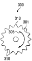
在一些实施方式中,底座10包括第一轴环21和第二轴环22。在图解实施方式中的第一轴环21和第二轴环22被配置为分别调节第一支柱100和第二支柱200沿底座10长度的运动。图解实施方式的第一轴环21通过固定在孔23中(图2和10),并经过凹槽27(图4、6和7)的插针(未示出)耦联到底座10的核心20。第一轴环21可通过任何有效器件耦联到核心20,其包括但不限于通过扣环(through retaining ring)、紧定螺钉或凹槽27中的铆接。随着插针在凹槽27中行进,允许第一轴环21绕核心20旋转。图解的第一轴环21包括围绕其周长的齿形件25,齿形件25被配置为接收使第一轴环21相对于底座10的部分,例如核心20旋转的器械。例如并且没有限制地,齿形件25可接收在图13-17中示出的致动器械中的一个。In some embodiments, the
图解实施方式的第二轴环22通过固定在孔24中(图2、8和10),并经过凹槽28(图4、6和7)的插针(未示出)耦联到底座10的核心20。随着插针在凹槽28中行进,允许第二轴环22绕核心20旋转。第二轴环22可通过任何有效器件耦联到核心20,其包括但不限于通过扣环、紧定螺钉或凹槽28中的铆接。图解的第二轴环22包括围绕其周长的齿形件26,齿形件26被配置为接收使第二轴环22相对于底座10的部分,例如核心20旋转的器械。例如并且没有限制地,齿形件26可接收在图13-17中示出的致动器械中的一个。The
对于图解的实施方式,第一轴环21和第二轴环22可用器械同时转动。例如,图13和图14的器械或图15-17的器械可连接到核心20,从而同时转动第一轴环21和第二轴环22。在图解的配置中,第一轴环21和第二轴环22通过图13-17的器械中任意一个以相反方向转动。然而,因为第一轴环21和第二轴环22具有同样的螺纹图案,但从近端到远端转动,使其以相反方向旋转导致第一支柱100和第二支柱200同时一起移动和同时移动分开。也在本发明的实施方式下也考虑螺纹图案和齿轮的任何其它可操作结合。例如并且没有限制地,致动器械可仅具有两个相互咬合齿轮,因此在上面和下面的轴环以相同而不是相反的旋转方向移动。该配置可连同具有相反螺纹图案的轴环进行操作,例如一个具有右旋螺纹的轴环,和一个具有左旋螺纹的轴环。For the illustrated embodiment, the
第一支柱100和第二支柱200的实施方式在图2、4、9和10中图解。第一支柱100具有近端101和远端102。近端101在套管13内行进,并且远端102延伸越过底座10的第一末端11。如图解的,第一轴环21通过螺纹121耦联到第一支柱100(图7和10),以使通过第一轴环21的旋转引起第一支柱100沿底座10的长度运动。Embodiments of the
第二支柱200具有近端201和远端202。近端201在套管13内行进,并且远端202延伸越过底座10的第二末端12。如图解,第二轴环21通过螺纹122耦联到第二支柱200(图7、8和10),以使通过第二轴环22的旋转引起第二支柱200沿底座10的长度运动。The
一些实施方式的分离器15也有助于防止轴环的螺纹121、122与各自的支柱100、200脱离。沿螺纹产生功的转动力可生成合力,当力施加到螺纹时,该合力趋向于向底座10的中心推动支柱100、200。分离器15可接触各自的支柱100、200通常相反侧,从而抵消合力并允许轴环的螺纹121、122保持与支柱100、200啮合。The
图9和10图解与第二支柱200的近端201嵌合的第一支柱100的近端101。在一些实施方式中,第一支柱100的近端101与第二支柱200的近端201沿底座10长度的至少一部分在套管13内嵌合。在此使用的术语嵌合与该术语的变化指咬合在一起、混合或沿其长度交迭的组件。考虑将组件配置为在组件具有允许组件的部分相互经过并沿组件长度占据共同横截面平面的形状时嵌合。如应用于在图9和10中图解的实施方式,第一支柱100被配置为与第二支柱200嵌合,因为第一支柱100的腿形件111、112被成形为沿第一和第二支柱100、200的长度与在第二支柱200的腿形件211、212一起安装在共同的横截面平面中。更特别地,对于图解的实施方式,第一支柱100和第二支柱200每个都包括两个相反的、嵌合的腿形件111、112和211、212。每个图解的腿形件111、112、211、212都基本设置在底座10横截面的四分点(quarter point)处。在其它实施方式中,可仅具有两个腿形件,以使排除分离器组件,每个支柱100、200包括最大量的材料,如上面提到的。支柱的一些实施方式可包括多于两对的嵌合腿形件,其围绕底座的外围分布支柱承担的负载,从而减少负载偏心率,并因此减少支柱材料中的应力。9 and 10 illustrate the
支柱100、200的一个或两个远端102、202可包括与各自的邻近椎体连接的尾端件或鞋形件。鞋形件可包括对远端102、102添加成角配置的零件,因此植入物匹配或改变脊柱前凸、脊柱后凸的脊柱弯曲,或脊柱侧凸导致的弯曲。可选地或另外地,鞋形件可包括增强与椎骨连接的零件。例如并且没有限制地,鞋形件可包括齿形件、长钉、紧固件、开孔、滚花、粗糙表面,或有效增强与椎骨连接的任何表面处理或另外材料。One or both
轴环的另一实施方式在图11和12中图解。示出可在核心20的任一或两个末端上被替代的轴环222。轴环222可通过固定在孔224中,并经过凹槽27、28(图4、6和7)中任意一个的插针(未示出)耦联到底座10的核心20。随着插针在凹槽27、28中行进,允许轴环222绕核心20旋转。轴环222可通过任何有效器件耦联到核心20,包括但不限于通过扣环、紧定螺钉或凹槽27、28中的铆接。图解的轴环222包括围绕其周长的齿形件226,齿形件226被配置为接收使轴环222相对于底座10的部分旋转的器械。例如并且没有限制地,齿形件226可接收在图13-17中示出的致动器械中的一个。Another embodiment of a collar is illustrated in FIGS. 11 and 12 . A
具有远端102和在套管13内行进的近端101的第一支柱100可被配置为通过啮合机构250与轴环222耦联。啮合机构250围绕轴环222内径的一个或更多个片段布置。当轴环222在啮合机构250不与第一支柱100上的螺纹相互作用的第一旋转位置时,允许第一支柱100沿底座10移动。当轴环222在啮合机构250与第一支柱100上的螺纹耦联的第二旋转位置时,约束第一支柱100沿底座10的移动。对于图解的轴环222,在第一旋转位置和第二旋转位置之间的旋转移动为大约90度。轴环222和啮合机构250可在结合第二支柱200的底座10的第二末端12处相似采用。在支柱或啮合机构250的片段的螺纹中的一个或两个尺寸不同的其它实施方式中,在第一和第二旋转位置之间的旋转移动按比例地改变。图解实施方式的啮合机构250是与各自支柱的螺纹啮合的螺纹。在其它实施方式中,医疗植入物的扩展和收缩可通过棘轮齿或任何其它功能机构调节。具有合适啮合机构250的轴环222的实施方式与这些其它机构同样有效,并在本发明的实施方式下考虑。
可扩展医疗植入物的另一实施方式在图18和19中图解。示出的可扩展医疗植入物1001包括底座1010、第一支柱1100和第二支柱1200。图解底座1010具有核心1020、第一轴环1021和第二轴环1022。底座1010具有第一末端1011和第二末端1012。图解的核心1020是大体圆柱形的,并包括开孔,用于第一和第二支柱1100、1200中的一个或两个经过核心1020。套管1013沿底座1010的长度在底座1010的第一末端1011和底座1010的第二末端1012之间延伸。在图18中,套管1013由第一和第二支柱1100、1200占据。示出的底座1010具有用于接收致动器械的开孔1017。开孔1017的配置和功能以及相关结构基本相似于上面关于开孔17描述的配置和功能以及相关结构。Another embodiment of an expandable medical implant is illustrated in FIGS. 18 and 19 . The illustrated expandable
在图解实施方式中的第一轴环1021和第二轴环1022被配置为分别调节第一支柱1100和第二支柱1200沿底座1010长度的运动。第一支柱1021通过固定在孔1023中(图18),并经过核心1020中凹槽(未示出)的插针(未示出)耦联到底座1010的核心1020。随着插针在凹槽中行进,允许第一轴环1021绕核心1020旋转。第一轴环1021可通过任何有效器件耦联到核心1020,其包括但不限于通过扣环、紧定螺钉或凹槽中的铆接。图解的第一轴环1021包括围绕其周长的齿形件1025,齿形件1025被配置为接收使第一轴环1021相对于底座1010的部分,例如核心1020旋转的器械。例如并且没有限制地,齿形件1025可接收在图13-17中示出的致动器械中的一个。The first collar 1021 and the
第二轴环22通过固定在孔1024中(图18和19),并经过核心1020中凹槽(未示出)的插针(未示出)耦联到底座1010的核心1020。随着插针在凹槽中行进,允许第二轴环1022绕核心1020旋转。第二轴环1022可通过任何有效器件耦联到核心1020,其包括但不限于通过扣环、紧定螺钉或凹槽中的铆接。图解的第二轴环1022包括围绕其周长的齿形件1026,齿形件1026被配置为接收使第二轴环1022相对于底座1010的部分,例如核心1020旋转的器械。例如并且没有限制地,齿形件1026可接收在图13-17中示出的致动器械中的一个。具有致动器械的第一和第二轴环1021和1022的操作与上面描述的第一和第二轴环21和22的操作基本相似。The
第一支柱1100和第二支柱1200的实施方式在图18和19中图解。第一支柱1100具有近端1101和远端1102。近端1101在套管1013内行进,并且远端1102延伸越过底座1010的第一末端1011。如图解的,第一轴环1021通过螺纹耦联到第一支柱1100,以使通过第一轴环1021的旋转引起第一支柱1100沿底座1010的长度运动。Embodiments of the
第二支柱1200具有近端1201和远端1202。近端1201在套管1013内行进,并且远端1202延伸越过底座1020的第二末端1012。如图解,第二轴环1022通过螺纹耦联到第二支柱1200,以使通过第二轴环1022的旋转引起第二支柱1200沿底座1010的长度运动。因为第二支柱1200具有小于第一支柱1100的直径,所以第二轴环1022中的带螺纹开孔1922(图19)小于第一轴环1021中的带螺纹开孔1911(图18)。带螺纹开孔1911和1922的螺距可以是相同螺距或不同螺距。不同螺距可在一些实施方式中有用,以响应共有致动使第一和第二支柱1100、1200以不同速率行进。由于更长的第二支柱能够嵌套通过第一支柱的中心并一直延伸到第一支柱的远端,因此不同速率行进也可通过使第二支柱比第一支柱更长容许更大的总扩展能力。更长的第二支柱可在其全部长度上以更快速率扩展,并由此给予植入物更大的总扩展距离。The
如在图19中示出,第一支柱1100的近端1101与第二支柱1200的近端1201嵌合。如应用于在图18和19中图解的实施方式,第一支柱1100被配置为通过在第一支柱1100的内径里面接收第二支柱1200与第二支柱1200嵌合。图解实施方式的第一和第二支柱1100、1200是管状、圆形横截面并有螺纹的。然而在其它实施方式中,支柱可以是椭圆形、三角形、矩形、正方形、其它多边形或曲线形状,或所述形状的结合或其它功能形状。各种实施方式可以具有或可以不具有螺纹,并可以可选地或另外地具有棘轮、槽口,或可被啮合或抓握以移动或把持第一和第二支柱的其它表面。As shown in FIG. 19 , the
中心孔1190在图18和19中示出。中心孔1190可完全或部分扩展通过第一和第二支柱1100、1200中的一个或两个。中心孔1190可完全或部分填充有骨生长促进物质,例如下面描述的物质。骨生长促进物质可在植入之前、在植入物的扩展过程期间、在植入物植入并完全扩展之后,或在列出时间的任何结合,添加到中心孔1190。
在一些实施方式下的可扩展医疗植入物是间隔开椎骨结构的工具。可扩展医疗植入物可包括底座,该底座具有第一末端、第二末端和沿底座的长度在第一和第二末端之间延伸的套管;第一支柱,其具有在套管内行进的近端和延伸越过底座第一末端的远端;第二支柱,其具有在套管内行进的近端和延伸越过底座第二末端的远端。可扩展医疗植入物的实施方式可进一步包括扩展工具,用于在套管中以相反方向相对于底座延伸第一支柱并相对于底座延伸第二支柱,因此通过第一支柱远端和第二支柱远端之间距离限定的第二高度大于通过第一支柱远端和第二支柱远端之间距离限定的第一高度两倍。在图解实施方式中,第一支柱100是单独组件,并且第二支柱200是单独组件。因此,为使远端102、202之间扩展的第二高度大于第一高度两倍,第一支柱100和第二支柱200在底座10内嵌合。在一些实施方式中,例如但不限于在图18和19中图解的实施方式,第一和第二支柱可嵌合为从底座相反末端延伸的同心圆柱横截面。An expandable medical implant under some embodiments is a tool for spacing apart vertebral structures. The expandable medical implant may include a base having a first end, a second end, and a sleeve extending along the length of the base between the first and second ends; a proximal end and a distal end extending beyond the first end of the base; a second strut having a proximal end that travels within the cannula and a distal end extending beyond the second end of the base. Embodiments of the expandable medical implant may further include an expansion tool for extending the first strut relative to the base and the second strut relative to the base in opposite directions in the sleeve, thus passing the first strut distal end and the second strut. The second height defined by the distance between the distal ends of the struts is greater than twice the first height defined by the distance between the distal ends of the first and second struts. In the illustrated embodiment, the
致动器械300、400在图13-17中图解。致动器械300、400被配置为与一些实施方式的一个或更多个轴环21、22、222、1021、1022中一起操作,以分别调节第一支柱100、1100和第二支柱200、1200沿底座10长度的运动。如在图13和14中图解,致动器械300的实施方式包括具有齿轮齿310的单齿轮301,齿轮齿310被配置为与轴环21、22、222、1021、1022中的一个或更多的齿形件25、26、226、1025、1026啮合。致动器械300包括其中轴330可旋转耦联的管320。抓握表面325可应用于管320的外部部分。把手335可包括在轴330的近端上用于抓取,以使轴330相对于管320转动。轴330耦联到齿轮301。键形物(tab)317可在开孔17中可旋转耦联,以将致动器械300固定到底座10,同时允许齿轮301相对于底座10转动。一些实施方式的键形物317可包括带螺纹的部分,以连接开孔17的带螺纹区,其中带螺纹的部分相对于轴330旋转。在其它实施方式中,键形物317可包括扩展或另外改变形状的器件,以可旋转或固定地与开孔17或底座10的其它部分连接。如在图14中通过箭头305示出,齿轮301的旋转导致在齿轮顶部相对于齿轮301以第一方向的运动,以及在齿轮底部以与第一方向相反的第二方向的运动。该配置可与器件例如可扩展医疗植入物1一起使用,其中该动作导致第一轴环21和第二轴环22反方向旋转,以及支柱100、200同时向收缩或扩展状态移动。在多种实施方式中,齿轮301的直径可被更改以配合在齿轮之间具有不同距离G的植入物(图2)。The
如在图15-17中示出,致动器械400的实施方式包括具有齿轮齿411、412、413的三个齿轮401、402、403。齿轮齿412、413被配置为与轴环21、22、222、1021、1022中的一个或更多的齿形件25、26、226、1025、1026啮合。致动器械400包括其中轴430可旋转耦联的管420。抓握表面425可应用于管420的外部部分。在示出的实施方式中,外壳450耦联到管420。键形物417被耦联到外壳450。把手435可包括在轴430的近端上用于抓取,以使轴430相对于管420转动。轴430耦联到齿轮401。键形物417在图解实施方式中具有三个尖头(prong),并可插入相似于底座10的底座中的开孔,以将致动器械400固定到底座,同时允许齿轮401相对于底座转动。其中在图解实施方式中致动器械400插入的开孔相似于开孔17的一些实施方式,但包括至少用于三个尖头的孔。一些实施方式的键形物417的尖头中一个或更多个可包括带螺纹的部分,以连接到开孔的带螺纹区。键形物417可包括扩展、改变取向或另外改变形状的器件,以与底座或植入物的另一部分连接。在图16中,为图解目的,示出外壳450的末端部分去除。如在图16中通过箭头405示出的,齿轮401的旋转导致在齿轮401顶部相对于齿轮401以第一方向的运动,以及在齿轮401底部以与第一方向相反的第二方向的运动。齿轮401在其顶部以通过箭头406示出的旋转方向咬合并转动齿轮402。齿轮401在其底部以通过箭头407示出的旋转方向咬合并转动齿轮403。该配置可与器件例如可扩展医疗植入物1一起使用,其中该动作导致第一轴环21和第二轴环22反方向旋转,以及支柱100、200同时向收缩或扩展状态移动。在多种实施方式中,齿轮401、402、403的直径可被更改以配合在齿轮之间具有不同距离G的植入物(图2),或生成不同量的机械利益或相对转动速率。例如并且没有限制地,轴环21、22、222、1021、1022在一些实施方式中可从顶部到底部更狭窄,并在轴环的齿轮之间产生更大的距离G。与致动器械300的把手335的相似旋转相比,致动器械400的把手435的旋转导致轴环21、22、222、1021、1022的相反旋转。在另一实施方式中,致动器械(未示出)可包括两个齿轮,因此该器械上下部分的旋转在共有方向上。这样的旋转对于植入物的上下轴环具有相反螺纹方向可以是有用的,或可用于各种其它植入物实施方式。As shown in FIGS. 15-17 , the embodiment of the
本发明的实施方式是间隔开椎体的方法。该方法可包括提供可扩展医疗植入物和扩展该植入物,以便该医疗植入物具有大于在未扩展状态的植入物或植入物组件的高度两倍的扩展高度。例如,本方法的可扩展医疗植入物能够具有在第一支柱的远端和第二支柱的远端之间的第一高度,并能够扩展到在第一支柱的远端和第二支柱的远端之间的大于第一高度的第二高度。该方法也可包括通过在套管中以相反方向移动第一和第二支柱,相对于底座扩展第一支柱并相对于底座扩展第二支柱,以便第二高度大于第一高度两倍。An embodiment of the invention is a method of spacing vertebral bodies. The method may include providing an expandable medical implant and expanding the implant such that the medical implant has an expanded height greater than twice the height of the implant or implant assembly in an unexpanded state. For example, the expandable medical implant of the present method can have a first height between the distal end of the first strut and the distal end of the second strut, and can expand to a height between the distal end of the first strut and the distal end of the second strut. A second height greater than the first height between the distal ends. The method may also include expanding the first strut relative to the base and expanding the second strut relative to the base by moving the first and second struts in opposite directions within the casing such that the second height is greater than twice the first height.
参考非限制例子,可扩展医疗植入物具有底座10,底座10具有第一末端11、第二末端12和沿底座10的长度在底座10的第一末端11和底座10的第二末端12之间延伸的套管13。图解的第一支柱100具有在套管13内行进的近端101和延伸越过底座10的第一末端11的远端102。图解的第二支柱200具有在套管13内行进的近端201和延伸越过底座10的第二末端12的远端202。在该例子中,在第一支柱100的远端102和第二支柱200的远端202之间限定第一高度。可扩展医疗植入物1可以能够扩展到在第一支柱100的远端102和第二支柱200的远端202之间的大于第一高度的第二高度。图解实施方式的第一支柱100是不伸缩、折叠或具有另外组件以任何方式扩展越过其远端102的单一件。同样,图解实施方式的第二支柱200是不伸缩、折叠或具有另外组件以任何方式扩展越过其远端202的单一件。图解实施方式的支柱100、200的近端101、201的直径或横向外周近似相等,因此给予支柱100、200近似相同的结构特性和负载能力。By way of non-limiting example, an expandable medical implant has a base 10 with a
继续本例子,扩展医疗植入物1包括相对于底座10扩展第一支柱100并相对于底座10扩展第二支柱200。示出的实施方式的扩展包括在套管13中以相反方向移动第一和第二支柱100、200,以便医疗植入物1具有大于第一高度两倍的第二高度。在一些实施方式中,扩展距离也可定义为扩展到大于底座10高度两倍的总高度。对于示出的器件,通过使与支柱100、200上的螺纹啮合的轴环21、22旋转,第一支柱10和第二支柱20相对于底座10移动。特别地,通过插入器械的尖端,例如致动器械300、400的键形物317、417中的任意一个,至底座10中,并使器械各自的把手335、435旋转以转动与轴环21、22的齿形件25、26咬合的一个或更多个齿轮,旋转轴环21、22。在其它实施方式中,轴环21、22的任意一个可独立地转动以选择性控制从底座10的任一末端扩展。Continuing with the example, expanding the medical implant 1 includes extending the
在可选的实施方式中,通过附联扩展器械到第一支柱的远端和第二支柱的远端,使可扩展医疗植入物扩展。扩展器械可具有能够移动远端相互远离的任何种类。例如并且没有限制地,具有对散布或压缩邻近组件、螺钉传动器件、棘轮器件、液压、电或其它动力的器件反应的机械联动的扩展器械可用来移动支柱的远端分开。方法实施方式包括操作这样的器械以使可扩展医疗植入物扩展。在扩展后,可扩展医疗植入物可通过任何有效机构锁定到适当位置。非限制例子包括用插针、紧定螺钉或其它紧固件、锁环、夹具、干涉配合与轴环锁定。轴环的更具体例子在轴环222中体现。方法实施方式可进一步包括在啮合机构250不与支柱100、200上的螺纹相互作用,同时支柱100、200相对于底座10移动的第一旋转位置,安置轴环。在支柱100、200移动到可接受位置时,轴环222可移动到啮合机构250与各自支柱100、200上的螺纹耦联,因此约束支柱100、200沿底座10移动的第二旋转位置。如图解的,在第一旋转位置和第二旋转位置之间的旋转移动为大约90度。在支柱100、200或啮合机构250的片段的螺纹中的一个或两个尺寸不同的其它实施方式中,在第一和第二旋转位置之间的旋转移动按比例地改变。In an alternative embodiment, the expandable medical implant is expanded by attaching an expansion instrument to the distal end of the first strut and the distal end of the second strut. The expansion instruments may be of any kind capable of moving the distal ends away from each other. For example and without limitation, expansion instruments with mechanical linkages responsive to spreading or compressing adjacent components, screw drive means, ratchet means, hydraulic, electrical or other powered means may be used to move the distal ends of the struts apart. Method embodiments include operating such an instrument to expand an expandable medical implant. After expansion, the expandable medical implant can be locked into place by any effective mechanism. Non-limiting examples include locking with pins, set screws or other fasteners, locking rings, clamps, interference fits, and collars. A more specific example of a collar is embodied in
一些实施方式也可包括作为可扩展医疗植入物的部分的补充固定器件,用于进一步稳定解剖。例如并且没有限制地,棒杆和螺钉固定系统、前部或横向镀覆系统(plating system)、小面稳定系统、棘突稳定系统,以及补充稳定的任何器件可用作可扩展医疗植入物的一部分。Some embodiments may also include supplemental fixation devices as part of the expandable medical implant for further stabilization of the anatomy. For example and without limitation, rod and screw fixation systems, anterior or lateral plating systems, facet stabilization systems, spinous process stabilization systems, and any device that supplements stabilization may be used as expandable medical implants a part of.
在一些实施方式中,可扩展医疗植入物也可包括骨生长促进物质作为可扩展医疗植入物的一部分或与其结合。植入物内部和/或外围的全部或部分可用合适的骨生长促进物质或治疗组分包裹。例如并且没有限制地,末端腔室105、205中的一个或两个(图2)可填充有骨生长促进物质例如成骨材料以促进骨生长入可扩展医疗植入物1的各自远端102、202。在其它实施方式中,腔室可以以鞋形件产生以放置在支柱的末端,或腔室可延伸可在扩展期间或之后填充的可扩展医疗植入物的全部长度。在图18和19中示出的中心孔1190可整体或部分地填充有骨生长促进物质。骨生长促进物质包括而不限于自体移植物、异体移植物、异种移植物、脱钙骨、人造或天然骨移植替代物,例如生物陶瓷和聚合物,以及骨诱导因子。也可使用在器件内保持材料的分离载体。这些载体可包括基于胶原的载体、生物陶瓷材料例如BIOGLASS羟磷灰石和磷酸钙组分。载体材料可以以海绵体、块体、折叠片、油灰、糊剂、移植材料的形式或其它合适形式提供。成骨组分可分离地或保持在合适载体材料内地包括有效量的骨形态发生蛋白(BMP)、转化生长因子β1、胰岛素样生长因子、血小板源性生长因子、成纤维细胞生长因子、LIM矿化蛋白(LMP)及其结合,或其它治疗或抗感染剂。放置可直接实现或借助于任何有效类型的注射或传递器件(transfer device)实现。In some embodiments, the expandable medical implant may also include a bone growth promoting substance as part of or in combination with the expandable medical implant. All or part of the interior and/or periphery of the implant may be coated with a suitable bone growth promoting substance or therapeutic composition. For example and without limitation, one or both of the end chambers 105, 205 ( FIG. 2 ) may be filled with a bone growth promoting substance such as an osteogenic material to promote bone growth into the respective
植入物的实施方式可整体或部分由各种类型的生物相容材料构造。植入物材料的例子包括但不限于非增强聚合物、增强的聚合物复合材料、PEEK和PEEK复合材料、形状记忆合金、钛、钛合金、钴铬合金、不锈钢、陶瓷及其结合。增强材料可包括碳、玻璃纤维、金属片或任何其它有效的增强材料。如果试验器械或植入物由射线可透材料制作,那么放射照相标记可设置在试验器械或植入物上,以提供射线照相地和荧光地监控和确定椎间盘空间中椎体位置的能力。在一些实施方式中,植入物或植入物的单独组件可由骨骼或其它组织的固体段构造。在其它实施方式中,植入物由装配成最终配置的骨骼支架构造。该植入物可由沿穿过植入物一个或更多个纵轴的水平或垂直平面装配的骨骼支架构造。组织材料包括但不限于人造或天然自体移植物、异体移植物或异种移植物,并可以是性质上可再吸收或不可再吸收的。其它组织材料的例子包括但不限于硬组织、结缔组织、脱钙骨基质及其结合。可使用的可再吸收材料的例子包括但不限于聚交酯、聚乙醇酸交酯、酪氨酸衍生聚碳酸酯、聚酐、聚原酸酯、聚磷腈、磷酸钙、羟磷灰石、生物活性玻璃及其结合。植入物可以是固体的、多孔的、海绵状的、穿孔的、钻孔的和/或打开的。Embodiments of the implant may be constructed, in whole or in part, from various types of biocompatible materials. Examples of implant materials include, but are not limited to, unreinforced polymers, reinforced polymer composites, PEEK and PEEK composites, shape memory alloys, titanium, titanium alloys, cobalt chromium alloys, stainless steel, ceramics, and combinations thereof. Reinforcement materials may include carbon, fiberglass, sheet metal, or any other effective reinforcement material. If the trial device or implant is made of radiolucent material, radiographic markers may be placed on the trial device or implant to provide the ability to radiographically and fluoroscopically monitor and determine the position of the vertebral bodies in the disc space. In some embodiments, an implant or individual components of an implant may be constructed from a solid segment of bone or other tissue. In other embodiments, the implant is constructed from a bone scaffold assembled into a final configuration. The implant may be constructed from a bone scaffold fitted along a horizontal or vertical plane passing through one or more longitudinal axes of the implant. Tissue material includes, but is not limited to, artificial or natural autografts, allografts, or xenografts, and may be resorbable or non-resorbable in nature. Examples of other tissue materials include, but are not limited to, hard tissue, connective tissue, decalcified bone matrix, and combinations thereof. Examples of resorbable materials that may be used include, but are not limited to, polylactide, polyglycolide, tyrosine-derived polycarbonate, polyanhydrides, polyorthoesters, polyphosphazenes, calcium phosphate, hydroxyapatite , Bioactive glass and combinations thereof. Implants may be solid, porous, spongy, perforated, drilled and/or open.
图1图解典型腰椎的四块椎骨V1-V4和三块椎间盘D1-D3。尽管本发明的实施方式可应用于腰椎区,但实施方式也可应用于颈椎或胸椎或其它骨骼结构之间。Figure 1 illustrates the four vertebrae V1 - V4 and the three intervertebral discs D1 - D3 of a typical lumbar spine. Although embodiments of the present invention may be applied to the lumbar region, embodiments may also be applied between cervical or thoracic vertebrae or other bony structures.
尽管本发明的实施方式在本公开中详细说明和描述,但是应考虑本公开为说明性的并且不约束特性。考虑在本发明精神内的全部改变和修改在本公开的范畴之内。While embodiments of the invention have been illustrated and described in this disclosure, the disclosure should be considered illustrative and not restrictive in nature. All changes and modifications within the spirit of the invention are contemplated to be within the scope of this disclosure.
Claims (16)
Applications Claiming Priority (3)
| Application Number | Priority Date | Filing Date | Title |
|---|---|---|---|
| US12/428,988 | 2009-04-23 | ||
| US12/428,988 US8292963B2 (en) | 2009-04-23 | 2009-04-23 | Expandable implant for supporting skeletal structures |
| PCT/US2010/031920 WO2010124008A2 (en) | 2009-04-23 | 2010-04-21 | Expandable implant, instrument, and method |
Publications (2)
| Publication Number | Publication Date |
|---|---|
| CN102421391A true CN102421391A (en) | 2012-04-18 |
| CN102421391B CN102421391B (en) | 2015-01-21 |
Family
ID=42556218
Family Applications (1)
| Application Number | Title | Priority Date | Filing Date |
|---|---|---|---|
| CN201080017450.1A Expired - Fee Related CN102421391B (en) | 2009-04-23 | 2010-04-21 | Expandable implant, instrument, and method |
Country Status (6)
| Country | Link |
|---|---|
| US (1) | US8292963B2 (en) |
| EP (1) | EP2421477B1 (en) |
| JP (1) | JP5624607B2 (en) |
| CN (1) | CN102421391B (en) |
| AU (1) | AU2010239299B2 (en) |
| WO (1) | WO2010124008A2 (en) |
Cited By (6)
| Publication number | Priority date | Publication date | Assignee | Title |
|---|---|---|---|---|
| CN108451618A (en) * | 2017-02-22 | 2018-08-28 | 医晟有限公司 | Vertebral lamina stabilizer for vertebra |
| CN111419488A (en) * | 2016-01-28 | 2020-07-17 | 华沙整形外科股份有限公司 | Geared Cam Expandable Intervertebral Implant and Implantation Method |
| CN112274302A (en) * | 2020-11-24 | 2021-01-29 | 四川大学华西医院 | Multi-unit adjustable intelligent interbody fusion cage |
| US12004963B2 (en) | 2015-10-16 | 2024-06-11 | Warsaw Orthopedic, Inc. | Expandable spinal implant system and method |
| US12310855B2 (en) | 2021-09-09 | 2025-05-27 | Warsaw Orthopedic, Inc. | End cap and bone screw for use therewith |
| US12403018B2 (en) | 2016-11-01 | 2025-09-02 | Warsaw Orthopedic, Inc. | Expandable spinal implant system and method of using same |
Families Citing this family (67)
| Publication number | Priority date | Publication date | Assignee | Title |
|---|---|---|---|---|
| US6595998B2 (en) | 2001-03-08 | 2003-07-22 | Spinewave, Inc. | Tissue distraction device |
| US7041309B2 (en) | 2002-06-13 | 2006-05-09 | Neuropro Technologies, Inc. | Spinal fusion using an HMG-CoA reductase inhibitor |
| US8236029B2 (en) | 2004-08-11 | 2012-08-07 | Nlt Spine Ltd. | Devices for introduction into a body via a substantially straight conduit to for a predefined curved configuration, and methods employing such devices |
| US8597360B2 (en) | 2004-11-03 | 2013-12-03 | Neuropro Technologies, Inc. | Bone fusion device |
| US9526525B2 (en) | 2006-08-22 | 2016-12-27 | Neuropro Technologies, Inc. | Percutaneous system for dynamic spinal stabilization |
| US8721723B2 (en) | 2009-01-12 | 2014-05-13 | Globus Medical, Inc. | Expandable vertebral prosthesis |
| US9387090B2 (en) * | 2009-03-12 | 2016-07-12 | Nuvasive, Inc. | Vertebral body replacement |
| US8747472B2 (en) * | 2009-08-14 | 2014-06-10 | Baxano Surgical, Inc. | Spinal therapy device with fixated distraction distance |
| JP2013512040A (en) * | 2009-11-25 | 2013-04-11 | スパイン21エル・ティー・ディー | Spinal rod with adjustable dimensions after surgery |
| AU2011227293A1 (en) | 2010-03-16 | 2012-11-08 | Pinnacle Spine Group, Llc | Intervertebral implants and graft delivery systems and methods |
| US8591585B2 (en) | 2010-04-12 | 2013-11-26 | Globus Medical, Inc. | Expandable vertebral implant |
| US9301850B2 (en) | 2010-04-12 | 2016-04-05 | Globus Medical, Inc. | Expandable vertebral implant |
| US9579211B2 (en) | 2010-04-12 | 2017-02-28 | Globus Medical, Inc. | Expandable vertebral implant |
| US11426287B2 (en) | 2010-04-12 | 2022-08-30 | Globus Medical Inc. | Expandable vertebral implant |
| US9271842B2 (en) | 2010-04-12 | 2016-03-01 | Globus Medical, Inc. | Expandable trial assembly for expandable vertebral implant |
| US8282683B2 (en) | 2010-04-12 | 2012-10-09 | Globus Medical, Inc. | Expandable vertebral implant |
| US8870880B2 (en) | 2010-04-12 | 2014-10-28 | Globus Medical, Inc. | Angling inserter tool for expandable vertebral implant |
| DE102010018379B4 (en) | 2010-04-26 | 2018-10-18 | Peter Metz-Stavenhagen | Spine implant and tool for this |
| RU2013102417A (en) | 2010-07-15 | 2014-08-20 | ЭнЭлТи Спайн ЛТД. | SURGICAL SYSTEMS AND METHODS OF IMPLANTING IMPLANTS OF VARIABLE FORM |
| US8740980B2 (en) * | 2011-01-27 | 2014-06-03 | Warsaw Orthopedic, Inc. | Expandable medical implant |
| DE102011002076A1 (en) * | 2011-04-15 | 2012-10-18 | Z.-Medical Gmbh & Co. Kg | Intervertebral implant and device for insertion |
| DE102011018692B4 (en) * | 2011-04-26 | 2016-06-23 | Peter Metz-Stavenhagen | Spinal implant, tool and method of distraction of the spinal implant |
| US8690886B2 (en) | 2011-06-30 | 2014-04-08 | Blackston Medical, Inc. | Posterior insertion instrument for an expandable support device |
| US8585763B2 (en) | 2011-06-30 | 2013-11-19 | Blackstone Medical, Inc. | Spring device for locking an expandable support device |
| US10420654B2 (en) | 2011-08-09 | 2019-09-24 | Neuropro Technologies, Inc. | Bone fusion device, system and method |
| WO2013023098A1 (en) | 2011-08-09 | 2013-02-14 | Neuropro Spinal Jaxx Inc. | Bone fusion device, apparatus and method |
| US10292830B2 (en) | 2011-08-09 | 2019-05-21 | Neuropro Technologies, Inc. | Bone fusion device, system and method |
| US9380932B1 (en) | 2011-11-02 | 2016-07-05 | Pinnacle Spine Group, Llc | Retractor devices for minimally invasive access to the spine |
| WO2013149134A2 (en) * | 2012-03-30 | 2013-10-03 | Olympus Biotech Corporation | Alif spinal implant |
| US9532883B2 (en) * | 2012-04-13 | 2017-01-03 | Neuropro Technologies, Inc. | Bone fusion device |
| US10159583B2 (en) | 2012-04-13 | 2018-12-25 | Neuropro Technologies, Inc. | Bone fusion device |
| WO2013179102A1 (en) | 2012-05-29 | 2013-12-05 | NLT-Spine Ltd. | Laterally deflectable implant |
| US9271844B2 (en) * | 2013-03-13 | 2016-03-01 | Warsaw Orthopedic, Inc. | Expandable spinal implant system and method |
| WO2014159739A1 (en) | 2013-03-14 | 2014-10-02 | Pinnacle Spine Group, Llc | Interbody implants and graft delivery systems |
| US9668773B2 (en) * | 2013-03-14 | 2017-06-06 | Globus Medical, Inc. | Spinal implant for use in thoracic insufficiency syndrome |
| US10098757B2 (en) | 2013-03-15 | 2018-10-16 | Neuropro Technologies Inc. | Bodiless bone fusion device, apparatus and method |
| US9968460B2 (en) | 2013-03-15 | 2018-05-15 | Medsmart Innovation Inc. | Dynamic spinal segment replacement |
| US10149770B2 (en) | 2013-07-09 | 2018-12-11 | Seaspine, Inc. | Orthopedic implant with adjustable angle between tissue contact surfaces |
| US9566167B2 (en) | 2013-08-22 | 2017-02-14 | K2M, Inc. | Expandable spinal implant |
| US9820865B2 (en) | 2013-10-31 | 2017-11-21 | Nlt Spine Ltd. | Adjustable implant |
| WO2015087285A1 (en) | 2013-12-11 | 2015-06-18 | Nlt Spine Ltd. | Worm-gear actuated orthopedic implants & methods |
| US9808245B2 (en) | 2013-12-13 | 2017-11-07 | Covidien Lp | Coupling assembly for interconnecting an adapter assembly and a surgical device, and surgical systems thereof |
| US10492923B2 (en) | 2014-06-25 | 2019-12-03 | Seaspine, Inc. | Expanding implant with hinged arms |
| US9987095B2 (en) | 2014-06-26 | 2018-06-05 | Covidien Lp | Adapter assemblies for interconnecting electromechanical handle assemblies and surgical loading units |
| US9931138B2 (en) * | 2014-10-15 | 2018-04-03 | Globus Medical, Inc. | Orthopedic extendable rods |
| US10363142B2 (en) | 2014-12-11 | 2019-07-30 | K2M, Inc. | Expandable spinal implants |
| US9889018B2 (en) | 2015-03-23 | 2018-02-13 | Musc Foundation For Research Development | Expandable vertebral body replacement device and method |
| US9775719B2 (en) | 2015-03-23 | 2017-10-03 | Musc Foundation For Research Development | Expandable vertebral body replacement device and method |
| US12161563B2 (en) * | 2016-09-14 | 2024-12-10 | Globus Medical, Inc. | Systems and methods for expandable corpectomy spacer implantation |
| US11596526B2 (en) * | 2016-09-14 | 2023-03-07 | Globus Medical Inc. | Systems and methods for expandable corpectomy spacer implantation |
| US12485017B2 (en) * | 2016-09-14 | 2025-12-02 | Globus Medical, Inc. | Systems and methods for expandable corpectomy spacer implantation |
| AU2017363425B2 (en) * | 2016-11-28 | 2023-06-22 | Musc Foundation For Research Development | Expandable vertebral body replacement device and method |
| US10973657B2 (en) | 2017-01-18 | 2021-04-13 | Neuropro Technologies, Inc. | Bone fusion surgical system and method |
| US10213321B2 (en) | 2017-01-18 | 2019-02-26 | Neuropro Technologies, Inc. | Bone fusion system, device and method including delivery apparatus |
| US10111760B2 (en) | 2017-01-18 | 2018-10-30 | Neuropro Technologies, Inc. | Bone fusion system, device and method including a measuring mechanism |
| US10729560B2 (en) | 2017-01-18 | 2020-08-04 | Neuropro Technologies, Inc. | Bone fusion system, device and method including an insertion instrument |
| US10441430B2 (en) | 2017-07-24 | 2019-10-15 | K2M, Inc. | Expandable spinal implants |
| US10874434B2 (en) * | 2017-10-18 | 2020-12-29 | Texas Scottish Rite Hospital For Children | Deformable dynamization device |
| US11234839B2 (en) * | 2019-05-21 | 2022-02-01 | Mohammad Etminan | Device for implementing intervertebral fusion |
| US11058429B2 (en) | 2019-06-24 | 2021-07-13 | Covidien Lp | Load sensing assemblies and methods of manufacturing load sensing assemblies |
| EP4110234B1 (en) | 2020-02-24 | 2026-01-07 | Musc Foundation for Research Development | Expandable vertebral body replacement device |
| US11883300B2 (en) | 2020-06-15 | 2024-01-30 | Nofusco Corporation | Orthopedic implant system and methods of use |
| US12144742B2 (en) | 2020-06-15 | 2024-11-19 | Foundation Surgical Group, Inc. | Implant system and methods of use |
| US11723778B1 (en) * | 2021-09-23 | 2023-08-15 | Nofusco Corporation | Vertebral implant system and methods of use |
| EP4164524A4 (en) | 2020-06-15 | 2024-07-17 | Foundation Surgical Group, Inc. | INTRAVERTEBRAL IMPLANT SYSTEM AND METHOD OF USE |
| US11819209B2 (en) | 2021-08-03 | 2023-11-21 | Covidien Lp | Hand-held surgical instruments |
| CN119344928B (en) * | 2024-12-05 | 2025-09-26 | 合肥综合性国家科学中心能源研究院(安徽省能源实验室) | An experimental device for lower limb length changes during hip replacement surgery |
Citations (7)
| Publication number | Priority date | Publication date | Assignee | Title |
|---|---|---|---|---|
| DE3729600A1 (en) * | 1987-09-04 | 1989-03-16 | Aesculap Werke Ag | Implant for insertion between the vertebral bodies of the spine |
| CN1053004A (en) * | 1991-01-18 | 1991-07-17 | 王芬 | The adjustable artificial vertebral body of L type |
| US5336223A (en) * | 1993-02-04 | 1994-08-09 | Rogers Charles L | Telescoping spinal fixator |
| US5571192A (en) * | 1994-07-02 | 1996-11-05 | Heinrich Ulrich | Prosthetic vertebral implant |
| US20070028710A1 (en) * | 2003-05-14 | 2007-02-08 | Kilian Kraus | Height-adjustable implant to be inserted between vertebral bodies and corresponding handling tool |
| WO2008033457A2 (en) * | 2006-09-14 | 2008-03-20 | The University Of Toledo | Variable height vertebral body replacement implant |
| US20100179657A1 (en) * | 2009-01-14 | 2010-07-15 | Stout Medical Group, L.P. | Expandable support device and method of use |
Family Cites Families (26)
| Publication number | Priority date | Publication date | Assignee | Title |
|---|---|---|---|---|
| US1486723A (en) | 1921-07-12 | 1924-03-11 | Maurice F Bernson | Jack |
| FR2575059B1 (en) | 1984-12-21 | 1988-11-10 | Daher Youssef | SHORING DEVICE FOR USE IN A VERTEBRAL PROSTHESIS |
| DE4109941A1 (en) | 1991-03-26 | 1992-10-01 | Reljica Kostic Zlatko Dr | Flexible prosthesis for backbone - comprises flexible spring forming supporting element connected to two fixing elements attached to adjacent vertebrae |
| ES2041221B1 (en) | 1992-04-24 | 1994-05-16 | Alacreu Jose Vicente Barbera | PROCEDURE FOR THE PROSTHETIC VERTEBRAL SUBSTITUTION IN THE SURGERY OF MALIGNANT TUMORS AND PROTESIS FOR THE PRACTICE OF SUCH PROCEDURE. |
| DE4409392A1 (en) | 1994-03-18 | 1995-09-21 | Biedermann Motech Gmbh | Adjustable vertebral body |
| ES2238684T3 (en) | 1994-12-09 | 2005-09-01 | Sdgi Holdings, Inc. | SUBSTITUTION OF ADJUSTABLE VERTEBRAL BODY. |
| DE19519101B4 (en) | 1995-05-24 | 2009-04-23 | Harms, Jürgen, Prof. Dr. | Height adjustable vertebral body replacement |
| DE19622827B4 (en) | 1996-06-07 | 2009-04-23 | Ulrich, Heinrich | Implant for insertion between vertebrae as a placeholder |
| US6190414B1 (en) | 1996-10-31 | 2001-02-20 | Surgical Dynamics Inc. | Apparatus for fusion of adjacent bone structures |
| HK1038873B (en) * | 1998-10-15 | 2004-10-08 | Synthes Gmbh | Telescopic vertebral prosthesis |
| AR027685A1 (en) | 2000-03-22 | 2003-04-09 | Synthes Ag | METHOD AND METHOD FOR CARRYING OUT |
| FR2817462B1 (en) * | 2000-12-05 | 2003-08-08 | Stryker Spine Sa | IN SITU INTERSOMATIC SPINAL IMPLANT WITH HARD PASSAGE POINTS |
| DE10065232C2 (en) | 2000-12-27 | 2002-11-14 | Ulrich Gmbh & Co Kg | Implant for insertion between the vertebral body and surgical instrument for handling the implant |
| DE20109599U1 (en) | 2001-06-08 | 2001-08-23 | Aesculap AG & Co. KG, 78532 Tuttlingen | Spine replacement body |
| TW545211U (en) | 2001-08-29 | 2003-08-01 | Jung-Chiuan Ye | Device for fastening spine |
| DE10210214B4 (en) | 2002-03-02 | 2005-01-05 | Bernd Schäfer | Distractable spinal implant and tool for distraction |
| US20040186569A1 (en) | 2003-03-20 | 2004-09-23 | Berry Bret M. | Height adjustable vertebral body and disc space replacement devices |
| DE50309438D1 (en) | 2003-04-28 | 2008-04-30 | Synthes Gmbh | INTERVERTEBRAL IMPLANT |
| DE10357926B3 (en) | 2003-12-11 | 2005-09-01 | Deltacor Gmbh | Length adjustable spinal implant |
| US7674296B2 (en) | 2005-04-21 | 2010-03-09 | Globus Medical, Inc. | Expandable vertebral prosthesis |
| US7575601B2 (en) * | 2006-04-27 | 2009-08-18 | Warsaw Orthopedic, Inc. | Locking expandable implant and method |
| US7879096B2 (en) * | 2006-04-27 | 2011-02-01 | Warsaw Orthopedic, Inc. | Centrally driven expandable implant |
| US7981157B2 (en) * | 2006-04-27 | 2011-07-19 | Warsaw Orthopedic, Inc. | Self-contained expandable implant and method |
| US7758648B2 (en) * | 2006-04-27 | 2010-07-20 | Warsaw Orthopedic, Inc. | Stabilized, adjustable expandable implant and method |
| US8123809B2 (en) * | 2009-04-16 | 2012-02-28 | Warsaw Orthopedic, Inc. | Deployment system and method for an expandable vertebral implant |
| US9579211B2 (en) * | 2010-04-12 | 2017-02-28 | Globus Medical, Inc. | Expandable vertebral implant |
-
2009
- 2009-04-23 US US12/428,988 patent/US8292963B2/en not_active Expired - Fee Related
-
2010
- 2010-04-21 CN CN201080017450.1A patent/CN102421391B/en not_active Expired - Fee Related
- 2010-04-21 WO PCT/US2010/031920 patent/WO2010124008A2/en not_active Ceased
- 2010-04-21 AU AU2010239299A patent/AU2010239299B2/en not_active Ceased
- 2010-04-21 EP EP10718774.2A patent/EP2421477B1/en not_active Not-in-force
- 2010-04-21 JP JP2012507356A patent/JP5624607B2/en not_active Expired - Fee Related
Patent Citations (7)
| Publication number | Priority date | Publication date | Assignee | Title |
|---|---|---|---|---|
| DE3729600A1 (en) * | 1987-09-04 | 1989-03-16 | Aesculap Werke Ag | Implant for insertion between the vertebral bodies of the spine |
| CN1053004A (en) * | 1991-01-18 | 1991-07-17 | 王芬 | The adjustable artificial vertebral body of L type |
| US5336223A (en) * | 1993-02-04 | 1994-08-09 | Rogers Charles L | Telescoping spinal fixator |
| US5571192A (en) * | 1994-07-02 | 1996-11-05 | Heinrich Ulrich | Prosthetic vertebral implant |
| US20070028710A1 (en) * | 2003-05-14 | 2007-02-08 | Kilian Kraus | Height-adjustable implant to be inserted between vertebral bodies and corresponding handling tool |
| WO2008033457A2 (en) * | 2006-09-14 | 2008-03-20 | The University Of Toledo | Variable height vertebral body replacement implant |
| US20100179657A1 (en) * | 2009-01-14 | 2010-07-15 | Stout Medical Group, L.P. | Expandable support device and method of use |
Cited By (11)
| Publication number | Priority date | Publication date | Assignee | Title |
|---|---|---|---|---|
| US12004963B2 (en) | 2015-10-16 | 2024-06-11 | Warsaw Orthopedic, Inc. | Expandable spinal implant system and method |
| US12433765B2 (en) | 2015-10-16 | 2025-10-07 | Warsaw Orthopedic, Inc. | Expandable spinal implant system and method |
| CN111419488A (en) * | 2016-01-28 | 2020-07-17 | 华沙整形外科股份有限公司 | Geared Cam Expandable Intervertebral Implant and Implantation Method |
| US11737889B2 (en) | 2016-01-28 | 2023-08-29 | Warsaw Orthopedic, Inc. | Geared cam expandable interbody implant and method of implanting same |
| US12514714B2 (en) | 2016-01-28 | 2026-01-06 | Warsaw Orthopedic, Inc. | Geared cam expandable interbody implant and method of implanting same |
| US12403018B2 (en) | 2016-11-01 | 2025-09-02 | Warsaw Orthopedic, Inc. | Expandable spinal implant system and method of using same |
| CN108451618A (en) * | 2017-02-22 | 2018-08-28 | 医晟有限公司 | Vertebral lamina stabilizer for vertebra |
| CN108451618B (en) * | 2017-02-22 | 2020-10-16 | 医晟有限公司 | spine lamina stabilizer |
| CN112274302A (en) * | 2020-11-24 | 2021-01-29 | 四川大学华西医院 | Multi-unit adjustable intelligent interbody fusion cage |
| CN112274302B (en) * | 2020-11-24 | 2021-07-13 | 四川大学华西医院 | A multi-unit adjustable intelligent interbody cage |
| US12310855B2 (en) | 2021-09-09 | 2025-05-27 | Warsaw Orthopedic, Inc. | End cap and bone screw for use therewith |
Also Published As
| Publication number | Publication date |
|---|---|
| JP2012524622A (en) | 2012-10-18 |
| JP5624607B2 (en) | 2014-11-12 |
| EP2421477A2 (en) | 2012-02-29 |
| AU2010239299A1 (en) | 2011-10-27 |
| WO2010124008A2 (en) | 2010-10-28 |
| AU2010239299B2 (en) | 2015-11-05 |
| WO2010124008A3 (en) | 2010-12-23 |
| EP2421477B1 (en) | 2014-02-12 |
| US8292963B2 (en) | 2012-10-23 |
| US20100274357A1 (en) | 2010-10-28 |
| CN102421391B (en) | 2015-01-21 |
Similar Documents
| Publication | Publication Date | Title |
|---|---|---|
| CN102421391B (en) | Expandable implant, instrument, and method | |
| US7758648B2 (en) | Stabilized, adjustable expandable implant and method | |
| US7914581B2 (en) | Expandable implant, instrument, and method | |
| US7879096B2 (en) | Centrally driven expandable implant | |
| US11083592B2 (en) | Plastically deformable inter-osseous device | |
| US7981157B2 (en) | Self-contained expandable implant and method | |
| US7575601B2 (en) | Locking expandable implant and method | |
| US20140148902A1 (en) | Expandable implant, instrument, and method | |
| US8801788B2 (en) | Expandable medical implant | |
| AU2011279588B2 (en) | A plastically deformable inter-osseous device |
Legal Events
| Date | Code | Title | Description |
|---|---|---|---|
| C06 | Publication | ||
| PB01 | Publication | ||
| C10 | Entry into substantive examination | ||
| SE01 | Entry into force of request for substantive examination | ||
| C14 | Grant of patent or utility model | ||
| GR01 | Patent grant | ||
| CF01 | Termination of patent right due to non-payment of annual fee | ||
| CF01 | Termination of patent right due to non-payment of annual fee |
Granted publication date: 20150121 Termination date: 20170421 |