CN102396231A - Image-processing device and method - Google Patents
Image-processing device and method Download PDFInfo
- Publication number
- CN102396231A CN102396231A CN2010800174643A CN201080017464A CN102396231A CN 102396231 A CN102396231 A CN 102396231A CN 2010800174643 A CN2010800174643 A CN 2010800174643A CN 201080017464 A CN201080017464 A CN 201080017464A CN 102396231 A CN102396231 A CN 102396231A
- Authority
- CN
- China
- Prior art keywords
- pixel
- neighbor
- image
- prediction
- unit
- Prior art date
- Legal status (The legal status is an assumption and is not a legal conclusion. Google has not performed a legal analysis and makes no representation as to the accuracy of the status listed.)
- Pending
Links
Images


Classifications
-
- H—ELECTRICITY
- H04—ELECTRIC COMMUNICATION TECHNIQUE
- H04N—PICTORIAL COMMUNICATION, e.g. TELEVISION
- H04N19/00—Methods or arrangements for coding, decoding, compressing or decompressing digital video signals
- H04N19/50—Methods or arrangements for coding, decoding, compressing or decompressing digital video signals using predictive coding
- H04N19/503—Methods or arrangements for coding, decoding, compressing or decompressing digital video signals using predictive coding involving temporal prediction
- H04N19/51—Motion estimation or motion compensation
- H04N19/577—Motion compensation with bidirectional frame interpolation, i.e. using B-pictures
-
- H—ELECTRICITY
- H04—ELECTRIC COMMUNICATION TECHNIQUE
- H04N—PICTORIAL COMMUNICATION, e.g. TELEVISION
- H04N19/00—Methods or arrangements for coding, decoding, compressing or decompressing digital video signals
- H04N19/10—Methods or arrangements for coding, decoding, compressing or decompressing digital video signals using adaptive coding
- H04N19/102—Methods or arrangements for coding, decoding, compressing or decompressing digital video signals using adaptive coding characterised by the element, parameter or selection affected or controlled by the adaptive coding
- H04N19/103—Selection of coding mode or of prediction mode
- H04N19/11—Selection of coding mode or of prediction mode among a plurality of spatial predictive coding modes
-
- H—ELECTRICITY
- H04—ELECTRIC COMMUNICATION TECHNIQUE
- H04N—PICTORIAL COMMUNICATION, e.g. TELEVISION
- H04N19/00—Methods or arrangements for coding, decoding, compressing or decompressing digital video signals
- H04N19/10—Methods or arrangements for coding, decoding, compressing or decompressing digital video signals using adaptive coding
- H04N19/134—Methods or arrangements for coding, decoding, compressing or decompressing digital video signals using adaptive coding characterised by the element, parameter or criterion affecting or controlling the adaptive coding
- H04N19/146—Data rate or code amount at the encoder output
- H04N19/147—Data rate or code amount at the encoder output according to rate distortion criteria
-
- H—ELECTRICITY
- H04—ELECTRIC COMMUNICATION TECHNIQUE
- H04N—PICTORIAL COMMUNICATION, e.g. TELEVISION
- H04N19/00—Methods or arrangements for coding, decoding, compressing or decompressing digital video signals
- H04N19/10—Methods or arrangements for coding, decoding, compressing or decompressing digital video signals using adaptive coding
- H04N19/169—Methods or arrangements for coding, decoding, compressing or decompressing digital video signals using adaptive coding characterised by the coding unit, i.e. the structural portion or semantic portion of the video signal being the object or the subject of the adaptive coding
- H04N19/17—Methods or arrangements for coding, decoding, compressing or decompressing digital video signals using adaptive coding characterised by the coding unit, i.e. the structural portion or semantic portion of the video signal being the object or the subject of the adaptive coding the unit being an image region, e.g. an object
- H04N19/176—Methods or arrangements for coding, decoding, compressing or decompressing digital video signals using adaptive coding characterised by the coding unit, i.e. the structural portion or semantic portion of the video signal being the object or the subject of the adaptive coding the unit being an image region, e.g. an object the region being a block, e.g. a macroblock
-
- H—ELECTRICITY
- H04—ELECTRIC COMMUNICATION TECHNIQUE
- H04N—PICTORIAL COMMUNICATION, e.g. TELEVISION
- H04N19/00—Methods or arrangements for coding, decoding, compressing or decompressing digital video signals
- H04N19/10—Methods or arrangements for coding, decoding, compressing or decompressing digital video signals using adaptive coding
- H04N19/169—Methods or arrangements for coding, decoding, compressing or decompressing digital video signals using adaptive coding characterised by the coding unit, i.e. the structural portion or semantic portion of the video signal being the object or the subject of the adaptive coding
- H04N19/186—Methods or arrangements for coding, decoding, compressing or decompressing digital video signals using adaptive coding characterised by the coding unit, i.e. the structural portion or semantic portion of the video signal being the object or the subject of the adaptive coding the unit being a colour or a chrominance component
-
- H—ELECTRICITY
- H04—ELECTRIC COMMUNICATION TECHNIQUE
- H04N—PICTORIAL COMMUNICATION, e.g. TELEVISION
- H04N19/00—Methods or arrangements for coding, decoding, compressing or decompressing digital video signals
- H04N19/10—Methods or arrangements for coding, decoding, compressing or decompressing digital video signals using adaptive coding
- H04N19/189—Methods or arrangements for coding, decoding, compressing or decompressing digital video signals using adaptive coding characterised by the adaptation method, adaptation tool or adaptation type used for the adaptive coding
- H04N19/19—Methods or arrangements for coding, decoding, compressing or decompressing digital video signals using adaptive coding characterised by the adaptation method, adaptation tool or adaptation type used for the adaptive coding using optimisation based on Lagrange multipliers
-
- H—ELECTRICITY
- H04—ELECTRIC COMMUNICATION TECHNIQUE
- H04N—PICTORIAL COMMUNICATION, e.g. TELEVISION
- H04N19/00—Methods or arrangements for coding, decoding, compressing or decompressing digital video signals
- H04N19/46—Embedding additional information in the video signal during the compression process
-
- H—ELECTRICITY
- H04—ELECTRIC COMMUNICATION TECHNIQUE
- H04N—PICTORIAL COMMUNICATION, e.g. TELEVISION
- H04N19/00—Methods or arrangements for coding, decoding, compressing or decompressing digital video signals
- H04N19/50—Methods or arrangements for coding, decoding, compressing or decompressing digital video signals using predictive coding
- H04N19/503—Methods or arrangements for coding, decoding, compressing or decompressing digital video signals using predictive coding involving temporal prediction
- H04N19/51—Motion estimation or motion compensation
- H04N19/57—Motion estimation characterised by a search window with variable size or shape
-
- H—ELECTRICITY
- H04—ELECTRIC COMMUNICATION TECHNIQUE
- H04N—PICTORIAL COMMUNICATION, e.g. TELEVISION
- H04N19/00—Methods or arrangements for coding, decoding, compressing or decompressing digital video signals
- H04N19/50—Methods or arrangements for coding, decoding, compressing or decompressing digital video signals using predictive coding
- H04N19/593—Methods or arrangements for coding, decoding, compressing or decompressing digital video signals using predictive coding involving spatial prediction techniques
-
- H—ELECTRICITY
- H04—ELECTRIC COMMUNICATION TECHNIQUE
- H04N—PICTORIAL COMMUNICATION, e.g. TELEVISION
- H04N19/00—Methods or arrangements for coding, decoding, compressing or decompressing digital video signals
- H04N19/60—Methods or arrangements for coding, decoding, compressing or decompressing digital video signals using transform coding
- H04N19/61—Methods or arrangements for coding, decoding, compressing or decompressing digital video signals using transform coding in combination with predictive coding
Landscapes
- Engineering & Computer Science (AREA)
- Multimedia (AREA)
- Signal Processing (AREA)
- Compression Or Coding Systems Of Tv Signals (AREA)
Abstract
Description
技术领域 technical field
本发明涉及图像处理设备及方法,并且尤其涉及与基准块相邻的相邻像素存在于图像框外部的情况下也能够进行二次预测的图像处理设备及方法。The present invention relates to an image processing apparatus and method, and more particularly, to an image processing apparatus and method capable of secondary prediction even when adjacent pixels adjacent to a reference block exist outside an image frame.
背景技术 Background technique
近年来,通过采用用于处理作为数字信号的图像信息的编码系统并且利用图像信息特有的冗余性,同时针对高效信息传输和存储,对图像进行压缩编码以通过正交变换如离散余弦变换等和运动补偿压缩图像的设备正在普及。该编码方法的示例包括MPEG(运动图像专家组)等。In recent years, by adopting a coding system for processing image information as a digital signal and utilizing redundancy peculiar to image information, while aiming at efficient information transmission and storage, images are compression-coded to pass orthogonal transforms such as discrete cosine transforms, etc. Devices that compress images with motion compensation are gaining popularity. Examples of the encoding method include MPEG (Moving Picture Experts Group) and the like.
具体地,MPEG2(ISO/IEC13818-2)被定义为通用图像编码格式,并且是包含隔行扫描图像和逐行扫描图像二者以及标准分辨率图像和高清晰度图像的标准。例如,MPEG2如今已被广泛应用于专业用途和消费者用途的宽范围。例如在具有720×480像素的标准分辨率的隔行扫描图像的情况下,通过采用MPEG2压缩格式,分配4至8Mbps的代码量(比特率)。例如在具有1920×1088像素的高分辨率的隔行扫描图像的情况下,通过采用MPEG2压缩格式,分配18至22Mbps的代码量(比特率)。因此,可以实现高压缩率和优良的图像质量。Specifically, MPEG2 (ISO/IEC13818-2) is defined as a general-purpose image encoding format, and is a standard that includes both interlaced images and progressive images, as well as standard-resolution images and high-definition images. For example, MPEG2 is widely used today for a wide range of professional use and consumer use. For example, in the case of an interlaced image having a standard resolution of 720×480 pixels, by adopting the MPEG2 compression format, a code amount (bit rate) of 4 to 8 Mbps is allocated. For example, in the case of an interlaced image having a high resolution of 1920×1088 pixels, by adopting the MPEG2 compression format, a code amount (bit rate) of 18 to 22 Mbps is allocated. Therefore, high compression ratio and excellent image quality can be realized.
利用MPEG2,主要将适于广播用途的高图像质量编码作为对象,但不处理比MPEG1的代码量低的代码量(比特率),即,具有更高压缩率的编码格式。由于个人数字助理变得普及,预期对于这种编码格式的需求从今开始将会增加,并且响应于此,MPEG4编码格式已经被标准化。关于图像编码格式,其规范在1998年12月被批准作为ISO/IEC14496-2国际标准。With MPEG2, high image quality coding suitable for broadcasting is mainly targeted, but a code size (bit rate) lower than that of MPEG1, that is, a coding format with a higher compression rate is not dealt with. As personal digital assistants become popular, it is expected that the demand for this encoding format will increase from now on, and in response to this, the MPEG4 encoding format has been standardized. Regarding the image encoding format, its specification was approved in December 1998 as the ISO/IEC14496-2 international standard.
此外,近年来,以用于电视会议用途的图像编码为对象,作为H.26L(ITU-T Q6/16VCEG)的标准的标准化已经取得进展。已经知道,与传统的编码格式如MPEG2或MPEG4相比,尽管利用H.26L编码和解码需要更大的计算量,但实现了更高的编码效率。此外,当前作为MPEG4的活动的一部分,已经进行了如下标准化作为增强压缩视频编码的联合模型(Joint Model of Enhanced-Compression Video Coding),该标准化采用H.26L作为基础实现更高编码效率、利用该H.26L不支持的功能。就标准化日程来说,H.264和MPEG-4Part10(Advanced Video Coding,高级视频编码,在下文中称为H.264/AVC)已于2003年3月成为国际标准。In addition, in recent years, standardization as a standard of H.26L (ITU-T Q6/16VCEG) has progressed for image coding for video conferencing purposes. It is known that, compared with conventional encoding formats such as MPEG2 or MPEG4, encoding and decoding with H.26L require a larger amount of calculation, but achieve higher encoding efficiency. In addition, currently as part of MPEG4's activities, the following standardization has been carried out as a Joint Model of Enhanced-Compression Video Coding (Joint Model of Enhanced-Compression Video Coding), which uses H.26L as a basis to achieve higher coding efficiency, utilizing the Function not supported by H.26L. As far as the standardization schedule is concerned, H.264 and MPEG-4 Part10 (Advanced Video Coding, hereinafter referred to as H.264/AVC) have become international standards in March 2003.
此外,作为其扩展的包括诸如RGB、4∶2∶2、4∶4∶4等操作所必需的编码工具、MPEG-2规定的8×8DCT(离散余弦变换)和量化矩阵的FRExt(Fidelity Range Extension,保真度范围扩展)的标准化也在2005年2月完成。因此,获得了能够使用H.264/AVC良好地表达动画中的电影噪声的编码格式,并且将被用在诸如蓝光光盘(Blu-Ray Disc,注册商标)的广泛应用中。In addition, as its extension, it includes encoding tools necessary for operations such as RGB, 4:2:2, 4:4:4, 8×8DCT (discrete cosine transform) specified by MPEG-2 and FRExt (Fidelity Range Extension, fidelity range extension) was also standardized in February 2005. Accordingly, a coding format capable of expressing movie noise in animation well using H.264/AVC is obtained, and will be used in a wide range of applications such as Blu-Ray Disc (registered trademark).
然而,最近对更高压缩编码的需求增加,例如要压缩大约4000×2000像素的图像,其为高清晰(Hi-Vision)图像的四倍。另外,例如为了在有限传输能力的环境中(如因特网)散布高清晰图像,也需要更高压缩编码。因此,上述ITU-T下的VCEG(=Video Coding Expert Group,视频编码专家组)继续进行与提高编码效率有关的研究。Recently, however, there has been an increased demand for higher compression coding, for example, to compress an image of approximately 4000×2000 pixels, which is four times that of a high-definition (Hi-Vision) image. In addition, higher compression coding is also required, for example, for distributing high-definition images in an environment with limited transmission capacity such as the Internet. Therefore, the VCEG (=Video Coding Expert Group, Video Coding Expert Group) under the above-mentioned ITU-T continues to conduct research related to improving coding efficiency.
例如,在非专利文献1中提出用于以帧间预测进一步提高编码效率的二阶预测方法。将参考图1描述该二阶预测方法。For example, Non-Patent
在图1的示例中示出目标帧和基准帧,在目标帧中示出目标块A。In the example of FIG. 1 , a target frame and a reference frame are shown, and a target block A is shown in the target frame.
在基准帧和目标帧中获得关于目标块A的运动矢量mv(mv_x,mv_y)的情况下,计算目标块A和通过矢量mv与目标块A相关联的块B之间的差分信息(余差)。In the case where the motion vector mv(mv_x, mv_y) about the target block A is obtained in the reference frame and the target frame, the differential information (residual difference) between the target block A and the block B associated with the target block A through the vector mv ).
利用该二阶方法,不仅计算与目标块A有关的差分信息,而且还计算与目标块A相邻的相邻像素组A’和通过矢量mv与相邻像素组A’相关联的相邻像素组B’之间的差分信息。With this second-order method, not only the differential information related to the target block A is calculated, but also the neighboring pixel group A' adjacent to the target block A and the neighboring pixel group A' associated with the neighboring pixel group A' through the vector mv Differential information between group B'.
也就是说,从目标块A的左上地址(x,y)获得相邻像素组A’的每个像素的地址。并且,从通过运动矢量mv(mv_x,mv_y)与目标块A相关联的块B的左上地址(x+mv_x,y+mv_y)计算相邻像素组B’的每个像素的地址。这些地址被用于计算相邻像素组B’的差分信息。That is, the address of each pixel of the adjacent pixel group A' is obtained from the upper left address (x, y) of the target block A. And, the address of each pixel of the adjacent pixel group B' is calculated from the upper left address (x+mv_x, y+mv_y) of the block B associated with the target block A by the motion vector mv(mv_x, mv_y). These addresses are used to calculate difference information of adjacent pixel groups B'.
利用该二阶方法,在这样计算出的与目标块有关的差分信息和与相邻像素有关的差分信息之间进行根据H.264/AVC方法的帧内预测,由此生成二阶差分信息。所生成的二阶差分信息进行正交变换和量子化,与压缩图像一起编码,并被发送到解码侧。With this second-order method, intra prediction according to the H.264/AVC method is performed between thus calculated difference information about the target block and difference information about adjacent pixels, thereby generating second-order difference information. The generated second-order differential information is subjected to orthogonal transformation and quantization, encoded together with the compressed image, and sent to the decoding side.
非专利文献non-patent literature
非专利文件1:Sijia Chen、Jinpeng Wang、Shangwen Li和Lu Yu于VCEG-AD09,ITU-Telecommunications Standardization Sector STUDYGROUP Question 6 Video coding Experts Group(VCEG)上的″SecondOrder Prediction(SOP)in P Slice″,2008年7月16-18日Non-Patent Document 1: "Second Order Prediction (SOP) in P Slice" by Sijia Chen, Jinpeng Wang, Shangwen Li and Lu Yu on VCEG-AD09, ITU-Telecommunications Standardization Sector STUDYGROUP
发明内容 Contents of the invention
技术问题technical problem
现在,尽管目标块A总是存在于目标帧的图像框内,但是基准块B是否存在于基准帧的图像框内取决于目标块A的地址和运动矢量的值。Now, although the target block A always exists in the image frame of the target frame, whether the reference block B exists in the image frame of the reference frame depends on the address of the target block A and the value of the motion vector.
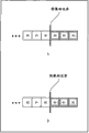
例如,在图2的示例中,在基准帧中检测关于目标块A的运动矢量mv1和mv2。通过运动矢量mv1与目标块A相关联的基准块B1的一部分从图像框的下部伸出,并且因此与基准块B1相邻的相邻像素组B1’的一部分也从图像框的下部伸出。For example, in the example of FIG. 2 , motion vectors mv1 and mv2 with respect to the target block A are detected in the reference frame. A part of the reference block B1 associated with the target block A by the motion vector mv1 protrudes from the lower part of the image frame, and thus a part of the adjacent pixel group B1' adjacent to the reference block B1 also protrudes from the lower part of the image frame.
另外,通过运动矢量mv2与目标块A相关联的基准块B2在图像框内,但与基准块B2相邻的相邻像素组B2’的一部分从图像框的右部伸出。In addition, the reference block B2 associated with the target block A by the motion vector mv2 is within the image frame, but a part of the adjacent pixel group B2' adjacent to the reference block B2 protrudes from the right part of the image frame.
也就是说,不仅基准块是否存在于图像框内取决于目标块A的地址和运动矢量的值,而且与基准块相邻的相邻像素组是否存在于图像框内也取决于目标块A的地址和运动矢量的值。在这种情况下不在图像框内的像素不可利用,所以不作为基准像素。That is to say, not only whether the reference block exists in the image frame depends on the address of the target block A and the value of the motion vector, but also whether the adjacent pixel group adjacent to the reference block exists in the image frame also depends on the value of the target block A Address and motion vector values. In this case, pixels that are not within the image frame are not available, so they are not used as reference pixels.
因此,如果应用非专利文献1中描述的二阶预测方法,则存在与基准块相邻的相邻像素不可利用的情况,并且在此情况下,难以进行二阶预测。Therefore, if the second-order prediction method described in
也就是说,利用非专利文献1中描述的二阶预测方法,H.264/AVC格式帧内预测转向二阶预测。利用H.264/AVC格式帧内预测,不需要对相邻像素的可用性进行确定,所以H.264/AVC格式帧内预测不能转为对用于二阶预测的相邻像素的可用性的确定。That is, using the second-order prediction method described in
因此,利用二阶预测,需要增加与相邻像素可用性的判定有关的电路。Therefore, with second-order prediction, it is necessary to add circuits related to the determination of the availability of adjacent pixels.
鉴于这种情况作出了本发明,并且即便在与基准块相邻的相邻像素存在于图像框的外部的情况下也能够进行二阶预测。The present invention has been made in view of such circumstances, and enables second-order prediction even when adjacent pixels adjacent to the reference block exist outside the image frame.
根据本发明第一方面的图像处理设备包括:确定装置,用于使用与目标帧中的目标块相邻的目标相邻像素的相对地址确定与基准帧中的基准块相邻的基准相邻像素是否存在于所述基准帧的图像框内;端点处理装置,用于在所述确定装置确定所述基准相邻像素不存在于所述图像框内的情况下对所述基准相邻像素进行端点处理;二阶预测装置,用于通过在所述目标块和所述基准块之间的差分信息与所述目标相邻像素和已经由所述端点处理装置对其进行了端点处理的所述基准相邻像素之间的差分信息之间进行预测来生成二阶差分信息;以及编码装置,用于对由所述二阶预测装置生成的所述二阶差分信息进行编码。The image processing apparatus according to the first aspect of the present invention includes: determining means for determining a reference adjacent pixel adjacent to a reference block in a reference frame using a relative address of a target adjacent pixel adjacent to a target block in a target frame Whether it exists in the image frame of the reference frame; endpoint processing means for performing endpoint processing on the reference adjacent pixel when the determination means determines that the reference adjacent pixel does not exist in the image frame processing; second-order predicting means for combining the target adjacent pixels with the target adjacent pixels and the reference which has been endpoint-processed by the endpoint processing means through differential information between the target block and the reference block Predicting difference information between adjacent pixels to generate second-order difference information; and encoding means for encoding the second-order difference information generated by the second-order prediction means.
该图像处理设备可以还包括计算装置,该计算装置用于利用所述目标块的地址(x,y)、所述目标块通过其参考所述基准块的运动矢量信息(dx,dy)和所述目标相邻像素的相对地址(δx,δy)计算所述基准相邻像素的相对地址(x+dx+δx,y+dy+δy),其中所述确定装置确定由所述计算装置计算出的所述基准相邻像素的所述相对地址(x+dx+δx,y+dy+δy)是否存在于图像框内。The image processing apparatus may further include calculating means for using the address (x, y) of the target block, the motion vector information (dx, dy) through which the target block refers to the reference block, and the The relative address (δx, δy) of the target adjacent pixel is used to calculate the relative address (x+dx+δx, y+dy+δy) of the reference adjacent pixel, wherein the determination means determines that the calculation means calculates Whether the relative address (x+dx+δx, y+dy+δy) of the reference adjacent pixel exists in the image frame.
在将像素值表示为n个比特的情况下,所述端点处理装置可以进行端点处理,使得x+dx+δx<0或y+dy+δy<0成立的基准相邻像素的像素值为2n-1。In the case of representing the pixel value as n bits, the endpoint processing means can perform endpoint processing, so that the pixel value of the reference adjacent pixel where x+dx+δx<0 or y+dy+δy<0 holds true is 2 n-1 .
在x+dx+δx>WIDTH-1成立的情况下,所述端点处理装置可以使用由地址(WIDTH-1,y+dy+δy)指示的像素值作为基准相邻像素的像素值进行端点处理,其中“WIDTH”代表图像框的水平方向上的像素的数目。In the case where x+dx+δx>WIDTH-1 holds true, the endpoint processing means can use the pixel value indicated by the address (WIDTH-1, y+dy+δy) as the pixel value of the reference adjacent pixel to perform endpoint processing , where "WIDTH" represents the number of pixels in the horizontal direction of the image frame.
在y+dy+δy>HEIGHT-1成立的情况下,所述端点处理装置可以使用由地址(x+dx+δx,HEIGHT-1)指示的像素值作为基准相邻像素的像素值进行端点处理,其中“HEIGHT”代表图像框的垂直方向上的像素的数目。In the case where y+dy+δy>HEIGHT-1 holds true, the endpoint processing means may use the pixel value indicated by the address (x+dx+δx, HEIGHT-1) as the pixel value of the reference adjacent pixel to perform endpoint processing , where "HEIGHT" represents the number of pixels in the vertical direction of the image frame.
在x+dx+δx>WIDTH-1和y+dy+δy>HEIGHT-1成立的情况下,所述端点处理装置可以使用由地址(WIDTH-1,HEIGHT-1)指示的像素值作为基准相邻像素的像素值进行端点处理,其中“WIDTH”代表图像框的水平方向上的像素的数目,“HEIGHT”代表图像框的垂直方向上的像素的数目。In the case where x+dx+δx>WIDTH-1 and y+dy+δy>HEIGHT-1 hold, the endpoint processing means may use the pixel value indicated by the address (WIDTH-1, HEIGHT-1) as the reference phase The pixel values of the adjacent pixels are subjected to endpoint processing, where "WIDTH" represents the number of pixels in the horizontal direction of the image frame, and "HEIGHT" represents the number of pixels in the vertical direction of the image frame.
所述端点处理装置可以针对不在图像框内的基准相邻像素进行端点处理,其中通过镜像处理在图像框的边界处对称地生成像素值。The endpoint processing means may perform endpoint processing on reference adjacent pixels not within the image frame, wherein pixel values are symmetrically generated at the border of the image frame by mirror image processing.
二阶预测装置可以还包括:帧内预测装置,用于使用所述目标相邻像素和已经由所述端点处理装置对其进行了端点处理的基准相邻像素之间的差分信息进行预测,以生成关于目标块的帧内预测图像;以及二阶差分生成装置,用于计算目标块和基准块之间的差分信息和由所述帧内预测装置生成的帧内预测图像的差分,以生成二阶差分信息。The second-order prediction means may further include: intra-frame prediction means for performing prediction using the difference information between the target adjacent pixels and the reference adjacent pixels for which endpoint processing has been performed by the endpoint processing means, to generating an intra-predicted image on the target block; and second-order difference generating means for calculating difference information between the target block and the reference block and a difference of the intra-predicted image generated by the intra-predicting means to generate two step difference information.
在所述确定装置确定所述基准相邻像素存在于所述图像框内时,所述二阶预测装置可以在所述目标块和所述基准块间的差分信息与所述目标相邻像素和所述基准相邻像素间的差分信息之间进行预测。When the determination means determines that the reference adjacent pixel exists in the image frame, the second-order prediction means may compare the difference information between the target block and the reference block with the target adjacent pixel and The difference information between the reference adjacent pixels is predicted.
根据本发明第一方面的图像处理方法包括以下步骤:图像处理设备使用与目标帧中的目标块相邻的目标相邻像素的相对地址确定与基准帧中的基准块相邻的基准相邻像素是否存在于所述基准帧的图像框内,在确定所述基准相邻像素不存在于所述图像框内的情况下对所述基准相邻像素进行端点处理,通过在所述目标块和所述基准块间的差分信息与所述目标相邻像素和已经对其进行端点处理的所述基准相邻像素间的差分信息之间进行预测来生成二阶差分信息,以及对所生成的二阶差分信息编码。The image processing method according to the first aspect of the present invention includes the following steps: the image processing device determines the reference adjacent pixels adjacent to the reference block in the reference frame using the relative addresses of the target adjacent pixels adjacent to the target block in the target frame Whether it exists in the image frame of the reference frame, if it is determined that the reference adjacent pixel does not exist in the image frame, perform endpoint processing on the reference adjacent pixel, by The difference information between the reference blocks and the difference information between the target adjacent pixels and the reference adjacent pixels that have been subjected to endpoint processing are predicted to generate second-order difference information, and the generated second-order Differential information encoding.
根据本发明第二方面的图像处理设备包括:解码装置,用于对编码的目标帧中的目标块的图像解码;确定装置,用于使用与所述目标块相邻的目标相邻像素的相对地址确定与基准帧中的基准块相邻的基准相邻像素是否存在于所述基准帧的图像框内;端点处理装置,用于在所述确定装置确定所述基准相邻像素不存在于所述图像框内的情况下对所述基准相邻像素进行端点处理;二阶预测装置,用于通过使用所述目标相邻像素和已经由所述端点处理装置对其进行了端点处理的所述基准相邻像素之间的差分信息进行二阶预测来生成预测图像;以及计算装置,用于将所述目标块的图像、由所述二阶预测装置生成的预测图像和所述基准块的图像相加以生成所述目标块的解码图像。The image processing apparatus according to the second aspect of the present invention includes: decoding means for decoding an image of a target block in an encoded target frame; determining means for using the relative values of target adjacent pixels adjacent to the target block Address determines whether a reference neighboring pixel adjacent to a reference block in a reference frame exists within an image frame of said reference frame; endpoint processing means for determining that said reference neighboring pixel does not exist in said determining means In the case of the image frame, the reference adjacent pixels are subjected to endpoint processing; the second-order prediction means is used to use the target adjacent pixels and the endpoint processing means to perform endpoint processing on it. performing second-order prediction on difference information between reference adjacent pixels to generate a predicted image; and computing means for combining the image of the target block, the predicted image generated by the second-order prediction means, and the image of the reference block sum to generate a decoded image of the target block.
该图像处理设备可以还包括计算装置,该计算装置用于利用所述目标块的地址(x,y)、所述目标块通过其参考所述基准块的运动矢量信息(dx,dy)和所述目标相邻像素的相对地址(δx,δy)计算所述基准相邻像素的相对地址(x+dx+δx,y+dy+δy),其中所述确定装置确定由所述计算装置计算出的所述基准相邻像素的所述相对地址(x+dx+δx,y+dy+δy)是否存在于图像框内。The image processing apparatus may further include calculating means for using the address (x, y) of the target block, the motion vector information (dx, dy) through which the target block refers to the reference block, and the The relative address (δx, δy) of the target adjacent pixel is used to calculate the relative address (x+dx+δx, y+dy+δy) of the reference adjacent pixel, wherein the determination means determines that the calculation means calculates Whether the relative address (x+dx+δx, y+dy+δy) of the reference adjacent pixel exists in the image frame.
在将像素值表示为n个比特的情况下,所述端点处理装置可以进行端点处理,使得x+dx+δx<0或y+dy+δy<0成立的基准相邻像素的像素值为2n-1。In the case of representing the pixel value as n bits, the endpoint processing means can perform endpoint processing, so that the pixel value of the reference adjacent pixel where x+dx+δx<0 or y+dy+δy<0 holds true is 2 n-1 .
在x+dx+δx>WIDTH-1成立的情况下,所述端点处理装置可以使用由地址(WIDTH-1,y+dy+δy)指示的像素值作为所述基准相邻像素的像素值进行所述端点处理,其中“WIDTH”代表图像框的水平方向上的像素的数目。In the case where x+dx+δx>WIDTH-1 holds true, the endpoint processing means may use the pixel value indicated by the address (WIDTH-1, y+dy+δy) as the pixel value of the reference adjacent pixel to perform The endpoint is processed, wherein "WIDTH" represents the number of pixels in the horizontal direction of the image frame.
在y+dy+δy>HEIGHT-1成立的情况下,所述端点处理装置可以使用由地址(x+dx+δx,HEIGHT-1)指示的像素值作为所述基准相邻像素的像素值进行所述端点处理,其中“HEIGHT”代表图像框的垂直方向上的像素的数目。In the case where y+dy+δy>HEIGHT-1 holds true, the endpoint processing means may use the pixel value indicated by the address (x+dx+δx, HEIGHT-1) as the pixel value of the reference adjacent pixel to perform The endpoint processing, where "HEIGHT" represents the number of pixels in the vertical direction of the image frame.
在x+dx+δx>WIDTH-1和y+dy+δy>HEIGHT-1成立的情况下,所述端点处理装置可以使用由地址(WIDTH-1,HEIGHT-1)指示的像素值作为所述基准相邻像素的像素值进行所述端点处理,其中“WIDTH”代表图像框的水平方向上的像素的数目,“HEIGHT”代表图像框的垂直方向上的像素的数目。In the case where x+dx+δx>WIDTH-1 and y+dy+δy>HEIGHT-1 hold, the endpoint processing means may use the pixel value indicated by the address (WIDTH-1, HEIGHT-1) as the The endpoint processing is performed with reference to pixel values of neighboring pixels, where "WIDTH" represents the number of pixels in the horizontal direction of the image frame, and "HEIGHT" represents the number of pixels in the vertical direction of the image frame.
所述端点处理装置可以针对不在图像框内的基准相邻像素进行端点处理,其中通过镜像处理在图像框的边界处对称地生成像素值。The endpoint processing means may perform endpoint processing on reference adjacent pixels not within the image frame, wherein pixel values are symmetrically generated at the border of the image frame by mirror image processing.
所述二阶预测装置可以还包括:预测图像生成装置,用于通过使用目标相邻像素和已经由所述端点处理装置对其进行了端点处理的所述基准相邻像素之间的差分信息进行二阶预测来生成预测图像。The second-order predicting means may further include: predicted image generating means for performing a process by using difference information between a target adjacent pixel and the reference adjacent pixel for which endpoint processing has been performed by the endpoint processing means. Second-order predictions are used to generate predicted images.
在所述确定装置确定所述基准相邻像素存在于所述图像框内的情况下,所述二阶预测装置可以使用所述目标相邻像素和所述基准相邻像素之间的差分信息进行预测。In the case where the determining means determines that the reference adjacent pixel exists within the image frame, the second-order predicting means may use difference information between the target adjacent pixel and the reference adjacent pixel to perform predict.
根据本发明第二方面的图像处理方法包括以下步骤:图像处理设备对编码的目标帧中的目标块的图像解码,使用与所述目标块相邻的目标相邻像素的相对地址确定与基准帧中的基准块相邻的基准相邻像素是否存在于所述基准帧的图像框内,在确定所述基准相邻像素不存在于所述图像框内的情况下对所述基准相邻像素进行端点处理,通过使用所述目标相邻像素和已经对其进行了端点处理的所述基准相邻像素之间的差分信息进行二阶预测来生成预测图像;以及将所述目标块的图像、由所述二阶预测装置生成的预测图像和所述基准块的图像相加以生成所述目标块的解码图像。The image processing method according to the second aspect of the present invention includes the following steps: the image processing device decodes the image of the target block in the coded target frame, and uses the relative address of the target adjacent pixel adjacent to the target block to determine the relative address of the reference frame Whether the reference adjacent pixels adjacent to the reference block in the reference block exist in the image frame of the reference frame, and if it is determined that the reference adjacent pixels do not exist in the image frame, the reference adjacent pixels are endpoint processing, generating a predicted image by performing second-order prediction using difference information between the target adjacent pixel and the reference adjacent pixel on which endpoint processing has been performed; and converting the image of the target block, by The predicted image generated by the second-order prediction means is added to the image of the reference block to generate a decoded image of the target block.
根据本发明的第一方面,使用与目标帧中的目标块相邻的目标相邻像素的相对地址确定与基准帧中的基准块相邻的基准相邻像素是否存在于基准帧的图像框内。在确定基准相邻像素不存在于图像框内的情况下,对基准相邻像素进行端点处理,通过在目标块和基准块间的差分信息与目标相邻像素和已经对其进行了端点处理的基准相邻像素间的差分信息之间进行预测生成二阶差分信息,并且将生成的二阶差分信息编码。According to the first aspect of the present invention, whether a reference neighboring pixel adjacent to a reference block in a reference frame exists within an image frame of a reference frame is determined using a relative address of a target neighboring pixel adjacent to a target block in a target frame . In the case that it is determined that the reference adjacent pixel does not exist in the image frame, the endpoint processing is performed on the reference adjacent pixel, and the difference information between the target block and the reference block is compared with the target adjacent pixel and the endpoint processing has been performed on it. Prediction is performed on difference information between reference adjacent pixels to generate second-order difference information, and the generated second-order difference information is encoded.
根据本发明的第二方面,对编码的目标帧中的目标块的图像解码,并且使用与目标帧中的目标块相邻的目标相邻像素的相对地址确定与基准帧中的基准块相邻的基准相邻像素是否存在于基准帧的图像框内。在确定基准相邻像素不存在于图像框内的情况下,对基准相邻像素进行端点处理,通过在目标块和基准块间的差分信息与目标相邻像素和已经对其进行了端点处理的基准相邻像素间的差分信息之间进行预测来生成二阶差分信息,以及将目标块的图像、由二阶预测装置生成的预测图像和基准块的图像相加以生成目标块的解码图像。According to the second aspect of the present invention, the coded image of the target block in the target frame is decoded, and the relative address of the target adjacent pixel adjacent to the target block in the target frame is used to determine the adjacent reference block in the reference frame Whether the benchmark neighbor pixel of is present within the image frame of the benchmark frame. In the case that it is determined that the reference adjacent pixel does not exist in the image frame, the endpoint processing is performed on the reference adjacent pixel, and the difference information between the target block and the reference block is compared with the target adjacent pixel and the endpoint processing has been performed on it. The differential information between reference adjacent pixels is predicted to generate secondary differential information, and the image of the target block, the predicted image generated by the secondary predicting means, and the image of the reference block are added to generate a decoded image of the target block.
注意,上述图像处理设备中的每一个可以是独立的设备,也可以是构成单个图像编码设备或图像解码设备的内部块。Note that each of the image processing devices described above may be an independent device, or may be an internal block constituting a single image encoding device or image decoding device.
发明的有益效果Beneficial Effects of the Invention
根据本发明的第一方面,可以对图像编码。另外,根据本发明的第一方面,即使在与基准块相邻的相邻像素存在于图像框的外部的情况下,也可以进行二阶预测。According to the first aspect of the present invention, an image can be encoded. In addition, according to the first aspect of the present invention, even when adjacent pixels adjacent to the reference block exist outside the image frame, second-order prediction can be performed.
根据本发明的第二方面,可以对图像解码。另外,根据本发明的第二方面,即使在与基准块相邻的相邻像素存在于图像框的外部的情况下,也可以进行二阶预测。According to the second aspect of the present invention, an image can be decoded. In addition, according to the second aspect of the present invention, even when adjacent pixels adjacent to the reference block exist outside the image frame, second-order prediction can be performed.
附图说明 Description of drawings
图1是描述帧间预测中的二阶预测系统的图。FIG. 1 is a diagram describing a second-order prediction system in inter prediction.
图2是描述与基准块相邻的相邻像素组的图。FIG. 2 is a diagram describing adjacent pixel groups adjacent to a reference block.
图3是示出应用了本发明的图像编码设备的实施例的配置的框图。Fig. 3 is a block diagram showing the configuration of an embodiment of an image encoding device to which the present invention is applied.
图4是用于描述块尺寸可变运动预测和补偿处理的图。FIG. 4 is a diagram for describing block size variable motion prediction and compensation processing.
图5是用于描述1/4像素精度的运动预测和补偿处理的图。FIG. 5 is a diagram for describing motion prediction and compensation processing of 1/4 pixel precision.
图6是用于描述多基准帧的运动预测和补偿方法的图。FIG. 6 is a diagram for describing a motion prediction and compensation method of a multi-reference frame.
图7是用于描述运动矢量信息生成方法的示例的图。FIG. 7 is a diagram for describing an example of a motion vector information generation method.
图8是示出图3中的二阶预测单元的配置示例的框图。FIG. 8 is a block diagram showing a configuration example of a second-order prediction unit in FIG. 3 .
图9是用于描述二阶预测单元和基准相邻确定单元的操作的图。FIG. 9 is a diagram for describing operations of a second-order prediction unit and a reference neighbor determination unit.
图10是用于描述基准相邻像素的设置的图。FIG. 10 is a diagram for describing setting of reference adjacent pixels.
图11是用于描述基准相邻像素的设置的图。FIG. 11 is a diagram for describing setting of reference adjacent pixels.
图12是用于描述端点处理的示例的图。FIG. 12 is a diagram for describing an example of endpoint processing.
图13是用于描述图3中的图像编码设备的编码处理的流程图。FIG. 13 is a flowchart for describing encoding processing of the image encoding device in FIG. 3 .
图14是用于描述图13中的步骤S21中的预测处理的流程图。FIG. 14 is a flowchart for describing prediction processing in step S21 in FIG. 13 .
图15是用于描述在16×16像素帧内预测模式的情况下的处理序列的图。FIG. 15 is a diagram for describing a processing sequence in the case of the 16×16 pixel intra prediction mode.
图16是示出用于辉度信号的各种4×4像素帧内预测模式的图。Fig. 16 is a diagram showing various 4x4 pixel intra prediction modes for a luminance signal.
图17是示出用于辉度信号的各种4×4像素帧内预测模式的图。Fig. 17 is a diagram showing various 4x4 pixel intra prediction modes for a luminance signal.
图18是用于描述4×4像素帧内预测的方向的图。FIG. 18 is a diagram for describing directions of 4×4 pixel intra prediction.
图19是用于描述4×4像素帧内预测的图。FIG. 19 is a diagram for describing 4×4 pixel intra prediction.
图20是用于描述用于辉度信号的4×4像素帧内预测模式的编码的图。FIG. 20 is a diagram for describing encoding of a 4×4 pixel intra prediction mode for a luminance signal.
图21是示出用于辉度信号的各种8×8像素帧内预测模式的图。Fig. 21 is a diagram showing various 8x8 pixel intra prediction modes for a luminance signal.
图22是示出用于辉度信号的各种8×8像素帧内预测模式的图。Fig. 22 is a diagram showing various 8x8 pixel intra prediction modes for a luminance signal.
图23是示出用于辉度信号的各种16×16像素帧内预测模式的图。FIG. 23 is a diagram showing various 16×16 pixel intra prediction modes for a luminance signal.
图24是示出用于辉度信号的各种16×16像素帧内预测模式的图。FIG. 24 is a diagram showing various 16×16 pixel intra prediction modes for a luminance signal.
图25是用于描述16×16像素帧内预测的图。FIG. 25 is a diagram for describing 16×16 pixel intra prediction.
图26是示出用于色差信号的各种帧内预测模式的图。Fig. 26 is a diagram showing various intra prediction modes for color difference signals.
图27是用于描述图14中步骤S31中的帧内预测处理的流程图。FIG. 27 is a flowchart for describing the intra prediction processing in step S31 in FIG. 14 .
图28是用于描述图14中步骤S32中的帧间运动预测处理的流程图。FIG. 28 is a flowchart for describing inter motion prediction processing in step S32 in FIG. 14 .
图29是用于描述图28中步骤S53中的基准相邻像素确定处理的流程图。FIG. 29 is a flowchart for describing reference adjacent pixel determination processing in step S53 in FIG. 28 .
图30是用于描述图28中步骤S54中的二阶预测处理的流程图。FIG. 30 is a flowchart for describing the second-order prediction processing in step S54 in FIG. 28 .
图31是示出应用了本发明的图像解码设备的实施例的配置示例的框图。Fig. 31 is a block diagram showing a configuration example of an embodiment of an image decoding device to which the present invention is applied.
图32是示出图31中的二阶预测单元的配置示例的框图。Fig. 32 is a block diagram showing a configuration example of a second-order prediction unit in Fig. 31 .
图33是用于描述图31中的图像解码设备的解码处理的流程图。Fig. 33 is a flowchart for describing decoding processing of the image decoding device in Fig. 31 .
图34是用于描述图33中步骤S138中的预测处理的流程图。FIG. 34 is a flowchart for describing prediction processing in step S138 in FIG. 33 .
图35是用于描述图34中步骤S179中的二阶帧间预测处理的流程图。Fig. 35 is a flowchart for describing the second-order inter prediction process in step S179 in Fig. 34 .
图36是示出计算机硬件的配置示例的框图。Fig. 36 is a block diagram showing a configuration example of computer hardware.
具体实施方式 Detailed ways
下面参考附图描述本发明的实施例。Embodiments of the present invention are described below with reference to the drawings.
图像编码设备的配置示例Configuration example of an image encoding device
图3示出作为应用了本发明的图像处理设备的图像编码设备的实施例的配置。FIG. 3 shows the configuration of an embodiment of an image encoding device as an image processing device to which the present invention is applied.
该图像编码设备51使用例如H.264和MPEG-4第十部分(AdvancedVideo Coding,高级视频编码)(在下文中称为264/AVC)格式对图像进行压缩编码。The
在图3的示例中,图像编码设备51由A/D转换单元61、画面排序缓冲器62、计算单元63、正交变换单元64、量子化单元65、无损编码单元66、存储缓冲器67、逆量子化单元68、逆正交变换单元69、计算单元70、解块过滤器71、帧存储器72、开关73、帧内预测单元74、运动预测/补偿单元75、二阶预测单元76、基准相邻确定单元77、预测图像选择单元78以及速率控制单元79构成。In the example of FIG. 3 , the
A/D转换单元61将输入图像从模拟转换为数字,并且输出到画面排序缓冲器62进行存储。画面排序缓冲器62将用于显示的存储顺序的各帧的图像排序为用于按照GOP(Group of Picture,图片组)编码的帧顺序。The A/
计算单元63从自画面排序缓冲器62读取的图像中减去由预测图像选择单元78选择的来自帧内预测单元74的预测图像或者来自运动预测/补偿单元75的预测图像,并将其差分信息输出到正交变换单元64。正交变换单元64对来自计算单元63的差分信息进行正交变换(如离散余弦变换、Karhunen-Loéve transform变换等),并输出其变换系数。量子化单元65将正交变换单元64输出的变换系数量子化。The
作为量子化单元65的输出的量子化的变换系数被输入到无损编码单元66、进行无损编码(如可变长编码、算术编码等)并被压缩。The quantized transform coefficients as the output of the
无损编码单元66从帧内预测单元74获取表示帧内预测的信息,并且从运动预测/补偿单元75获取表示帧间预测模式等的信息。注意,在下文中将表示帧内预测的信息和表示帧间预测的信息分别称为帧内预测模式信息和帧间预测模式信息。The
无损编码单元66对量子化的变换系数编码,并且还对表示帧内预测的信息、表示帧间预测模式的信息等编码,并且将它们作为压缩图像中的头信息的一部分。无损编码单元66将编码的数据提供给存储缓冲器67进行存储。The
例如,利用无损编码单元66进行如可变长编码、算术编码等的无损编码处理。可变长编码的示例包括由H.264/AVC格式确定的CAVLC(Context-Adaptive Variable Length Coding,基于上下文的自适应可变长编码)。算术编码的示例包括CABAC(Context-Adaptive BinaryArithmetic Coding,基于上下文的自适应二进制算术编码)。For example, lossless encoding processing such as variable length encoding, arithmetic encoding, and the like is performed with the
存储缓冲器67将从无损编码单元66提供的数据作为由H.264/AVC格式编码的压缩图像输出到图中未示出的下游的存储设备或传输路径等。The
此外,从量子化单元65输出的量子化变换系数还被输入到逆量子化单元68、进行逆量子化,然后还在逆正交变换单元69处进行逆正交变换。进行了逆正交变换的输出通过计算单元70与从预测图像选择单元78提供的预测图像相加,并且成为局部解码的图像。解块过滤器71从解码图像中去除块噪声,然后将其提供给帧存储器72进行存储。由解块过滤器71进行解块过滤处理之前的图像也被提供给帧存储器72进行存储。Furthermore, the quantized transform coefficient output from the
开关73将存储在帧存储器72中的基准图像输出到运动预测/补偿单元75或者帧内预测单元74。The
利用该图像编码设备51,例如来自画面排序缓冲器62的I图片、B图片和P图片被提供给帧内预测单元74,作为要进行帧内预测(也称为帧内处理)的图像。另外,从画面排序缓冲器62读取的B图片和P图片被提供给运动预测/补偿单元75,作为要进行帧间预测(也被称为帧间处理)的图像。With this
帧内预测单元74基于从画面排序缓冲器62读取的要进行帧内预测的图像和从帧存储器72提供的基准图像进行作为候选的所有帧内预测模式的帧内预测处理,以生成预测图像。The
此时,帧内预测单元74针对所有候选帧内预测模式计算成本函数值,并且选择所算出的成本函数值给出最小值的帧内预测模式作为最佳帧内预测模式。At this time, the
帧内预测单元74将在最佳帧内预测模式中生成的预测图像及其成本函数值提供给预测图像选择单元78。在预测图像选择单元78选择了最佳帧内预测模式中生成的预测图像的情况下,帧内预测单元74将表示最佳帧内预测模式的信息提供给无损编码单元66。无损编码单元66对该信息编码以作为压缩图像中头信息的一部分。The
运动预测/补偿单元75对于作为候选的所有帧间预测模式进行运动预测和补偿处理。具体地,从画面排序缓冲器62读取的要进行帧间处理的图像被提供给运动预测/补偿单元75,并且基准图像也从帧存储器72经由开关73提供给运动预测/补偿单元75。运动预测/补偿单元75基于要进行帧间处理的图像和基准图像检测作为候选的所有帧间预测模式的运动矢量、基于这些运动矢量对基准图像进行补偿处理,并生成预测图像。The motion prediction/
运动预测/补偿单元75将检测出的运动矢量信息、用于帧间处理的图像信息(地址等)以及作为要进行帧间处理的图像与所生成的预测图像之间的余差的一阶余差提供给二阶预测单元76。The motion prediction/
二阶预测单元76获取与使用运动矢量信息与目标块相关联的基准块相邻的基准相邻像素的地址,并且提供给基准相邻确定单元77。二阶预测单元76根据来自基准相邻确定单元77的对该输入的确定结果,对从帧存储器72读取的并经过二阶预测处理的相应像素进行端点处理。注意,端点处理是使用存在于基准帧的图像框内的另一个像素值确定用于该图像框外部发现的基准相邻像素的像素值的处理。此外,二阶预测是用于在一阶余差与目标相邻像素和基准相邻像素之间的差分之间进行预测并生成二阶差分信息(二阶余差)的处理。The second-
二阶预测单元76将通过二阶预测处理生成的二阶余差和用于二阶预测处理的帧内预测模式的信息输出到运动预测/补偿单元75作为二阶预测中的帧内预测模式信息。The second-
基准相邻确定单元77使用来自运动预测/补偿单元75的基准相邻像素的地址确定基准相邻像素是否存在于基准帧的图像框内,并且将其确定结果提供给二阶预测单元76。The reference
运动预测/补偿单元75可以通过比较来自二阶预测单元76的二阶余差来确定用于二阶预测的最佳帧内预测模式。此外,运动预测/补偿单元75通过比较二阶余差和一阶余差来确定是否进行二阶预测处理(即,是对二阶余差编码还是对一阶余差编码)。注意,关于所有候选帧间预测模式进行这些处理。The motion prediction/
此外,运动预测/补偿单元75对于作为候选的所有帧间预测模式计算成本函数值。此时,运动预测/补偿单元75使用一阶余差和二阶余差中针对每个帧间预测模式确定的余差计算成本函数值。运动预测/补偿单元75将计算出的成本函数值中提供最小值的预测模式确定为最佳帧间预测模式。Furthermore, the motion prediction/
运动预测/补偿单元75将在最佳帧间预测模式中生成的预测图像(或者要进行帧间的图像和二阶余差之间的差分)及其成本函数值提供给预测图像选择单元78。在预测图像选择单元78选择了最佳帧间预测模式中生成的预测图像的情况下,运动预测/补偿单元75将表示最佳帧间预测模式的信息输出到无损编码单元66。The motion prediction/
此时,运动矢量信息、基准帧信息和表示要进行二阶预测的二阶预测标记、用于二阶预测的帧内预测模式的信息等也被输出到无损编码单元66。无损编码单元66还对来自运动预测/补偿单元75的信息进行无损编码处理(如可变长编码、算术编码等),并插入到压缩图像的头部中。At this time, motion vector information, reference frame information, a second-order prediction flag indicating that second-order prediction is to be performed, information on an intra prediction mode for second-order prediction, and the like are also output to the
预测图像选择单元78基于从帧内预测单元74或运动预测/补偿单元75输出的成本函数值在最佳帧内预测模式和最佳帧间预测模式中确定最佳预测模式。然后预测图像选择单元78选择所确定的最佳预测模式中的预测图像,并提供给计算单元63和70。此时,预测图像选择单元78将预测图像的选择信息提供给帧内预测单元74或运动预测/补偿单元75。The predicted image selection unit 78 determines the optimum prediction mode among the optimum intra prediction mode and the optimum inter prediction mode based on the cost function value output from the
速率控制单元79基于存储在存储缓冲器67中的压缩图像控制量子化单元65的量子化操作的速率以避免引起溢出或下溢。The
H.264/AVC格式的描述Description of H.264/AVC format
图4是示出根据H.264/AVC格式的运动预测和补偿的块尺寸的示例的图。利用H.264/AVC格式,对可变化的块尺寸进行运动预测和补偿。FIG. 4 is a diagram illustrating an example of a block size of motion prediction and compensation according to the H.264/AVC format. Using the H.264/AVC format, motion prediction and compensation are performed on variable block sizes.
在图4中的上层从左侧依次示出由分割为16×16像素、16×8像素、8×16像素和8×8像素分区的16×16个像素构成的宏块。在图4中的下层从左侧依次示出分割为8×8像素、8×4像素、4×8像素和4×4像素子分区的8×8像素分区。The upper layer in FIG. 4 shows a macroblock composed of 16×16 pixels divided into 16×16 pixels, 16×8 pixels, 8×16 pixels, and 8×8 pixel partitions in order from the left. The lower layer in FIG. 4
具体地,利用H.264/AVC格式,可以将一个宏块分割为16×16像素、16×8像素、8×16像素和8×8像素分区中的一个,其中,每个分区具有独立的运动矢量信息。此外,可以将8×8像素分区分割为8×8像素、8×4像素、4×8像素和4×4像素子分区中的一个,其中,每个子分区具有独立的运动矢量信息。Specifically, using the H.264/AVC format, a macroblock can be divided into one of 16×16 pixel, 16×8 pixel, 8×16 pixel and 8×8 pixel partitions, wherein each partition has an independent Sports vector information. Furthermore, the 8x8 pixel partition may be divided into one of 8x8 pixel, 8x4 pixel, 4x8 pixel and 4x4 pixel sub-partitions, where each sub-partition has independent motion vector information.
图5是用于描述根据H.264/AVC格式的1/4像素精度的预测和补偿处理的图。根据H.264/AVC格式,使用6抽头FIR(Finite Impulse ResponseFilter,有限脉冲响应过滤器)进行1/4像素精度的预测和补偿处理。FIG. 5 is a diagram for describing prediction and compensation processing of 1/4 pixel precision according to the H.264/AVC format. According to the H.264/AVC format, use 6-tap FIR (Finite Impulse Response Filter, finite impulse response filter) for 1/4 pixel precision prediction and compensation processing.
在图5的示例中,位置A表示整数精度像素,位置b、c和d表示1/2像素精度的位置,位置e1、e2和e3表示1/4像素精度的位置。首先,下面将Clip()定义为如下表达式(1)。In the example of FIG. 5, position A represents an integer precision pixel, positions b, c and d represent positions of 1/2 pixel precision, and positions e1, e2 and e3 represent positions of 1/4 pixel precision. First, Clip() is defined below as the following expression (1).
[数学表达式1][mathematical expression 1]

注意,在输入图像具有8比特精度的情况下,max_pix的值为255。Note that the value of max_pix is 255 in case the input image has 8-bit precision.
使用6抽头FIR过滤器按如下表达式(2)生成位置b和d的像素值。Pixel values at positions b and d are generated using a 6-tap FIR filter as in the following expression (2).
[数学表达式2][mathematical expression 2]
F=A-2-5·A-1+20·A0+20·A1-5·A2+A3 F=A -2 -5·A -1 +20·A 0 +20·A 1 -5·A 2 +A 3
b,d=Clip1((F+16)>>5) …(2)b, d=Clip1((F+16)>>5) ...(2)
通过在水平方向和垂直方向上应用6抽头FIR过滤器按如下表达式(3)生成位置c的像素值。A pixel value at position c is generated by applying a 6-tap FIR filter in the horizontal direction and vertical direction as in the following expression (3).
[数学表达式3][mathematical expression 3]
F=b-2-5·b-1+20·b0+20·b1-5·b2+b3 F=b -2 -5·b -1 +20·b 0 +20·b 1 -5·b 2 +b 3
或者or
F=d-2-5·d-1+20·d0+20·d1-5·d2+d3 F=d -2 -5·d -1 +20·d 0 +20·d 1 -5·d 2 +d 3
c=Clip1((F+512)>>10) …(3)c=Clip1((F+512)>>10) …(3)
注意,在进行了水平方向和垂直方向上的积项和(sum-of-product)处理之后最终只进行一次Clip处理。Note that after performing the sum-of-product processing in the horizontal and vertical directions, only one Clip processing is finally performed.
通过如下表达式(4)中示出的线性插值生成位置e1至e3。The positions e1 to e3 are generated by linear interpolation shown in Expression (4) below.
[数学表达式4][mathematical expression 4]
e1=(A+b+1)>>1e 1 =(A+b+1)>>1
e2=(b+d+1)>>1e 2 =(b+d+1)>>1
e3=(b+c+1)>>1 …(4)e 3 =(b+c+1)>>1 …(4)
图6是用于描述根据H.264/AVC格式的多基准帧的预测和补偿处理的图。根据H.264/AVC格式,设置多基准帧(Multi-Reference Frame)的运动预测和补偿方法。FIG. 6 is a diagram for describing prediction and compensation processing of a multi-reference frame according to the H.264/AVC format. According to the H.264/AVC format, set the multi-reference frame (Multi-Reference Frame) motion prediction and compensation method.
在图6的示例中,示出从现在开始要编码的目标帧Fn和已经编码的帧Fn-5至Fn-1。在时间轴上,帧Fn-1比目标帧Fn早1帧,帧Fn-2比目标帧Fn早2帧,帧Fn-3比目标帧Fn早3帧。类似地,帧Fn-4比目标帧Fn早4帧,帧Fn-5比目标帧Fn早5帧。一般来说,在时间轴上离目标帧Fn越近的帧,要加的基准图片编号(ref_id)越小。具体地,帧Fn-1具有最小的基准图片编号,并且此后基准图片编号按Fn-2、…、Fn-5的顺序减小。In the example of FIG. 6 , a target frame Fn to be encoded from now on and already encoded frames Fn-5 to Fn-1 are shown. On the time axis, the frame Fn-1 is 1 frame earlier than the target frame Fn, the frame Fn-2 is 2 frames earlier than the target frame Fn, and the frame Fn-3 is 3 frames earlier than the target frame Fn. Similarly, frame Fn-4 is 4 frames earlier than target frame Fn, and frame Fn-5 is 5 frames earlier than target frame Fn. Generally speaking, the closer the frame is to the target frame Fn on the time axis, the smaller the reference picture number (ref_id) to be added. Specifically, the frame Fn-1 has the smallest reference picture number, and thereafter the reference picture numbers decrease in the order of Fn-2, . . . , Fn-5.
关于目标帧Fn,示出了块A1和块A2,在块A1与比目标帧Fn早2帧的帧Fn-2的块A1’相关联的假定下搜索运动矢量V1。类似地,在块A2与比目标帧Fn早4帧的帧Fn-4的块A1’相关联的假定下搜索运动矢量V2。Regarding the target frame Fn, block A1 and block A2 are shown, and the motion vector V1 is searched on the assumption that block A1 is associated with block A1' of frame Fn-2 which is 2 frames earlier than target frame Fn. Similarly, the motion vector V2 is searched on the assumption that the block A2 is associated with the block A1' of the frame Fn-4 which is 4 frames earlier than the target frame Fn.
如上所述,根据H.264/AVC格式,可以利用存储在存储器中的多个基准帧,在一个帧(图片)中参考不同的基准帧。具体地,例如,使得块A1参考帧Fn-2,块A2参考帧Fn-4,可以为一个图片中的每个块提供独立的基准帧信息(基准图片编号(ref_id))。As described above, according to the H.264/AVC format, it is possible to refer to different reference frames in one frame (picture) using a plurality of reference frames stored in the memory. Specifically, for example, making block A1 refer to frame Fn-2 and block A2 to refer to frame Fn-4, independent reference frame information (reference picture number (ref_id)) may be provided for each block in a picture.
在此,块表示参考图4描述的16×16像素、16×8像素、8×16像素和8×8像素分区之一。8×8像素子块分区内的基准帧必需一致。Here, the block means one of the 16×16 pixel, 16×8 pixel, 8×16 pixel, and 8×8 pixel divisions described with reference to FIG. 4 . The reference frames in the 8×8 pixel sub-block partition must be consistent.
根据H.264/AVC格式,通过执行上面参考图4至图6描述的运动预测和补偿处理,生成大量的运动矢量信息,并且如果不经改变就对这些信息进行编码,会引起编码效率恶化。响应于此,根据H.264/AVC格式,按照图7中所示的方法,实现了运动矢量编码信息的减少。According to the H.264/AVC format, by performing the motion prediction and compensation processing described above with reference to FIGS. 4 to 6 , a large amount of motion vector information is generated, and if the information is encoded without change, encoding efficiency will deteriorate. In response to this, according to the H.264/AVC format, according to the method shown in FIG. 7, reduction of motion vector encoding information is realized.
图7是用于描述根据H.264/AVC格式的运动矢量信息生成方法的图。FIG. 7 is a diagram for describing a motion vector information generation method according to the H.264/AVC format.
在图7的示例中,示出了现在要编码的目标块E(例如,16×16像素)和与目标块E相邻的已经编码的块A至D。In the example of FIG. 7 , a target block E (for example, 16×16 pixels) to be encoded now and already encoded blocks A to D adjacent to the target block E are shown.
具体地,块D与目标块E的左上相邻,块B与目标块E的上方相邻,块C与目标块E的右上相邻,块A与目标块E的左侧相邻。注意,块A至D没有被分割的理由是因为每个块代表具有上面参考图3描述的16×16像素至4×4像素的一个结构的块。Specifically, block D is adjacent to the upper left of the target block E, block B is adjacent to the upper side of the target block E, block C is adjacent to the upper right of the target block E, and block A is adjacent to the left side of the target block E. Note that the reason blocks A to D are not divided is because each block represents a block having a structure of 16×16 pixels to 4×4 pixels described above with reference to FIG. 3 .
例如,假定用mvX代表关于x(=A、B、C、D、E)的运动矢量信息。首先,通过使用关于块A、B、C的运动矢量信息的中值预测按如下表达式(5)生成关于目标块E的预测运动矢量信息pmvE。For example, assume that motion vector information on x (=A, B, C, D, E) is represented by mv X. First, the predicted motion vector information pmv E on the target block E is generated by the median prediction using the motion vector information on the blocks A, B, C as in the following expression (5).
pmvE=med(mvA,mvB,mvC) …(5)pmv E =med(mv A ,mv B ,mv C ) …(5)
由于图像框的边缘以及之前编码等原因,关于块C的运动矢量信息可能不被使用(可能是不可用的)。在此情况下,代替关于块C的运动矢量信息,使用关于块D的运动矢量信息。Motion vector information about block C may not be used (may not be available) due to the edges of the image frame, previous encoding, etc. In this case, instead of the motion vector information on the block C, the motion vector information on the block D is used.
使用pmvE按如下表达式(6)生成作为目标块E的运动矢量信息的、将添加至压缩图像的头部的数据mvdE。Data mvd E to be added to the header of the compressed image as motion vector information of the target block E is generated using pmv E as in the following expression (6).
mvdE=mvE-pmvE …(6)mvd E = mv E -pmv E ... (6)
注意,在现实中,关于运动矢量信息的水平方向和垂直方向的分量独立进行处理。Note that in reality, the horizontal and vertical components of the motion vector information are processed independently.
以这种方式生成预测运动矢量信息,作为基于与相邻块的相关性生成的预测运动矢量信息和运动矢量信息之间的差分的数据mvdE被添加至压缩图像的头部,从而可以减少运动矢量信息。The predicted motion vector information is generated in this way, the data mvd E that is the difference between the predicted motion vector information generated based on the correlation with the adjacent block and the motion vector information is added to the header of the compressed image, so that the motion can be reduced Vector information.
二阶预测单元的配置示例Configuration example of the second-order prediction unit
图8是示出二阶预测单元的详细配置示例的框图。Fig. 8 is a block diagram showing a detailed configuration example of a second-order prediction unit.
在图8的示例中,二阶预测单元76由基准块地址计算单元81、基准相邻地址计算单元82、基准相邻像素确定单元83、目标相邻像素读取单元84、相邻像素差分计算单元85、帧内预测单元86以及目标块差分缓冲器87构成。In the example of FIG. 8, the second-
运动预测/补偿单元75将目标块的运动矢量(dx,dy)提供给基准块地址计算单元81。运动矢量预测/补偿单元75将目标块地址(x,y)提供给基准块地址计算单元81和目标相邻像素读取单元84。运动矢量预测/补偿单元75将作为目标块和基准块(预测图像)之间的差分的一阶余差提供给目标块差分缓冲器87。The motion prediction/
基准块地址计算单元81根据来自运动矢量预测/补偿单元75的目标块地址(x,y)和目标块的运动矢量(dx,dy)确定基准块地址(x+dx,y+dy)。基准块地址计算单元81将确定的基准块地址(x+dx,y+dy)提供给基准相邻地址计算单元82。The reference block
基准相邻地址计算单元82基于基准块地址(x+dx,y+dy)和与目标块相邻的目标相邻像素的相对地址计算作为基准相邻像素的相对地址的基准相邻地址。基准相邻地址计算单元82将计算出的基准相邻地址(x+dx+δx,y+dy+δy)提供给基准相邻确定单元77。The reference adjacent
基准相邻像素是否存在于基准帧的图像框内的确定结果被从基准相邻确定单元77输入到基准相邻像素确定单元83。在相邻像素存在于基准帧的图像框内的情况下,基准相邻像素确定单元83从帧存储器72中读取以H.264/AVC定义的相邻像素并且将其存储在未示出的内置缓冲器中。The determination result of whether the reference adjacent pixel exists within the image frame of the reference frame is input from the reference
另一方面,在基准相邻像素不存在于基准帧的图像框内的情况下,基准相邻像素确定单元83对不存在的相邻像素进行端点处理以确定从帧存储器72中读取并存储在未示出的内置缓冲器中的基准相邻像素的像素值。在此,端点处理例如是取存在于基准帧的图像框内的另一个像素值作为不存在于图像框内的相邻像素的像素值的处理,稍后将参考图12详细描述端点处理。On the other hand, in the case that the reference adjacent pixel does not exist in the image frame of the reference frame, the reference adjacent
目标相邻像素读取单元84使用来自运动预测/补偿单元75的基准块地址(x,y)从帧存储器72读取目标块的像素值并将其存储在未示出的内置缓冲器中。The target adjacent
相邻像素差分计算单元85从建立在目标相邻像素读取单元84中的内置缓冲器中读取目标相邻像素[A’],并且还从建立在相邻像素差分计算单元85中的内置缓冲器中读取与目标相邻像素对应的基准相邻像素[B’]。然后相邻像素差分计算单元85计算从各自的内置缓冲器中读取的目标相邻像素[A’]和基准相邻像素[B’]之间的差分,并且将其作为相邻像素的余差[A’-B’]存储在未示出的内置缓冲器中。The adjacent pixel
帧内预测单元86从相邻像素差分计算单元85的内置缓冲器中读取相邻像素的余差[A’-B’],并且从目标块差分缓冲器87中读取目标块的一阶余差[A-B]。帧内预测单元86使用相邻像素的余差[A’-B’]以每个帧内预测模式[模式]对目标块进行帧内预测,并生成帧内预测图像Ipred(A’-B’)[模式]。The
然后,帧内预测单元86生成作为目标块的一阶余差和针对目标块预测的帧内预测图像之间的差分的二阶余差,并且将所生成的二阶余差和此时的帧内预测模式的信息提供给运动预测/补偿单元75。Then, the
注意,在图8的示例中的帧内预测单元86处进行作为二阶预测的帧内预测的电路可以与帧内预测单元75共用一个电路。Note that a circuit that performs intra prediction as second-order prediction at the
二阶预测单元和基准相邻确定单元的操作说明Operational Description of the Second-Order Prediction Unit and the Reference Neighborhood Determination Unit
接下来,参考图9描述二阶预测单元76和基准相邻确定单元77的操作。注意,以下描述针对目标块的块尺寸为4×4像素的情况。Next, operations of the second-
在图9的示例中,示出目标帧和基准帧,在目标帧中示出目标块A和与目标块A相邻的目标相邻像素A’。此外,在目标帧和基准帧之间示出在基准帧处取得的关于目标帧A的运动矢量(dx,dy)。In the example of FIG. 9 , a target frame and a reference frame are shown, and a target block A and a target adjacent pixel A' adjacent to the target block A are shown in the target frame. Also, a motion vector (dx, dy) about the target frame A obtained at the reference frame is shown between the target frame and the reference frame.
此外,在基准帧中示出通过运动矢量mv(dx,dy)与目标块A相关联的基准块B和与基准块B相邻的基准相邻像素B’。注意,在附图中,用阴影线示出目标相邻像素A’和基准相邻像素B’,以与目标块A和基准块B的像素区分。Furthermore, a reference block B associated with the target block A by a motion vector mv(dx, dy) and a reference neighboring pixel B' adjacent to the reference block B are shown in the reference frame. Note that in the drawings, the target neighboring pixel A' and the reference neighboring pixel B' are hatched to distinguish them from the pixels of the target block A and the reference block B.
首先,在二阶预测单元76进行上面参考图1描述的二阶预测处理。此时,由基准相邻确定单元77对基准块B的基准相邻像素B’是否存在于图像框内进行确定,并且在二阶预测单元76处进行如下设置。First, the second-order prediction processing described above with reference to FIG. 1 is performed at the second-
也就是说,如图9中所示,如果将位于目标块A的左上的像素的地址(坐标)定义为(x,y),则位于基准块B的左上的像素的地址因运动矢量mv(dx,dy)而被定义为(x+dx,y+dy)。That is, as shown in FIG. 9, if the address (coordinates) of the pixel located on the upper left of the target block A is defined as (x, y), the address of the pixel located on the upper left of the reference block B is changed by the motion vector mv( dx, dy) is defined as (x+dx, y+dy).
此时,利用如下表达式(7),将目标相邻像素A’的地址定义为(x+δx,y+δy),并且将目标相邻像素B’的地址定义为(x+dx+δx,y+dy+δy)。At this time, using the following expression (7), the address of the target adjacent pixel A' is defined as (x+δx, y+δy), and the address of the target adjacent pixel B' is defined as (x+dx+δx , y+dy+δy).
(δx,δy)={(-1,-1),(0,-1),(1,-1),(2,-1),(3,-1),(4,-1),(5,-1),(6,-1),(7,-1),(-1,0),(-1,1),(-1,2),(-1,3)} …(7)(δx, δy)={(-1,-1), (0,-1), (1,-1), (2,-1), (3,-1), (4,-1), (5, -1), (6, -1), (7, -1), (-1, 0), (-1, 1), (-1, 2), (-1, 3)} ... (7)
接下来,参考图10和图11描述使用这些地址设置基准块B的基准相邻像素B’。注意,目标块A的目标相邻像素A’的定义符合H.264/AVC的定义。也就是说,稍后将参考图13和图14描述其细节。Next, setting of the reference adjacent pixel B' of the reference block B using these addresses will be described with reference to FIGS. 10 and 11 . Note that the definition of the target adjacent pixel A' of the target block A complies with the definition of H.264/AVC. That is, details thereof will be described later with reference to FIGS. 13 and 14 .
首先,在图10中的A的示例中,示出与基准块B相邻的基准相邻像素B’的一部分从基准帧的图像框的左侧伸出到外部的示例。在图10中的B的示例中,示出与基准块B相邻的基准相邻像素B’的一部分从基准帧的图像框的上侧伸出到外部的示例。First, in the example of A in FIG. 10 , an example is shown in which a part of the reference adjacent pixel B' adjacent to the reference block B protrudes from the left side of the image frame of the reference frame to the outside. In the example of B in FIG. 10 , an example in which a part of the reference adjacent pixel B' adjacent to the reference block B protrudes from the upper side of the image frame of the reference frame to the outside is shown.
在这些情况下,即,对于如下表达式(8)成立时的基准相邻像素B’,二阶预测单元76将像素值设置为2n-1。在此,我们称像素值被表示为n个比特,并且在8个比特的情况下,像素值是128。In these cases, that is, for the reference adjacent pixel B′ when the following expression (8) holds, the second-
x+dx+δx<0或者y+dy+δy>0 …(8)x+dx+δx<0 or y+dy+δy>0 ...(8)
接下来,在图11中的A的示例中,示出基准相邻像素B’的一部分以及基准块B的一部分从基准帧的图像框的下侧伸出到外部的示例。在图11中的B的示例中,示出与基准块B相邻的基准相邻像素B’的一部分从基准帧的图像框的右侧伸出到外部的示例。Next, in the example of A in Fig. 11 , an example is shown in which a part of the reference neighboring pixel B' and a part of the reference block B protrude from the lower side of the image frame of the reference frame to the outside. In the example of B in FIG. 11 , an example in which a part of the reference neighboring pixel B' adjacent to the reference block B protrudes from the right side of the image frame of the reference frame to the outside is shown.
此时,我们称目标帧和基准帧的图像框尺寸为WIDTH×HEIGHT。如果图像框尺寸为WIDTH×HEIGHT,在例如图11中的A中所示的情况下,即,对于如下表达式(9)成立时的基准相邻像素B’,二阶预测单元76将地址(WIDTH-1,y+dy+δy)指示的像素设置为基准相邻像素。At this time, we call the image frame size of the target frame and the reference frame as WIDTH×HEIGHT. If the image frame size is WIDTH×HEIGHT, in the case shown, for example, in A in FIG. The pixel indicated by WIDTH-1, y+dy+δy) is set as the reference adjacent pixel.
x+dx+δx>WIDTH-1 …(9)x+dx+δx>WIDTH-1 ...(9)
此外,如果图像框尺寸为WIDTH×HEIGHT,在例如图11中的B中所示的情况下,即,如下表达式(10)成立时,二阶预测单元76将地址(x+dx+δx,HEIGHT-1)指示的像素设置为基准相邻像素。Furthermore, if the image frame size is WIDTH×HEIGHT, in the case shown in B in FIG. 11, for example, that is, when the following expression (10) holds, the second-
y+dy+δy>HEIGHT-1 …(10)y+dy+δy>HEIGHT-1 ...(10)
此外,如果图像框尺寸为WIDTH×HEIGHT,在表达式(9)和(10)二者都成立的情况下,二阶预测单元76将地址(WIDTH-1,HEIGHT-1)指示的像素设置为基准相邻像素。Furthermore, if the image frame size is WIDTH×HEIGHT, in the case where both expressions (9) and (10) are true, the second-
也就是说,对于如图11中的A和图11中的B中的箭头表示的从图像框伸出到外部的基准相邻像素,二阶预测单元76设置基准相邻像素的处理仅是使用与存在于图像框内的基准相邻像素的值相同的值,这是端点处理的一个类型。该处理被称为保持处理。注意,可以采用作为端点处理的另一个类型的镜像处理,代替保持处理。That is to say, for reference neighboring pixels protruding from the image frame to the outside as indicated by the arrows in A in FIG. 11 and B in FIG. 11 , the process of setting the reference neighboring pixels by the second-
接下来,参考图12描述作为端点处理的保持处理和镜像处理。注意,图11中的B中所示的E的范围在图12中的A的示例中被放大示出作为保持处理的示例,并且在图12中的B的示例中被放大示出作为镜像处理的示例。Next, hold processing and mirroring processing as endpoint processing are described with reference to FIG. 12 . Note that the range of E shown in B in FIG. 11 is shown enlarged in the example of A in FIG. 12 as an example of hold processing, and is shown enlarged in the example of B in FIG. 12 as mirror image processing example of .
从图像框边界起至图中左侧的基准相邻像素存在于图像框内,并且例如从图像框边界侧起依次具有像素值a0、a1和a2。然而,从图像框边界起至图中右侧的基准相邻像素存在于图像框的外部。Reference adjacent pixels from the image frame boundary to the left in the figure exist within the image frame, and have pixel values a0, a1, and a2 in order from the image frame boundary side, for example. However, the reference adjacent pixels from the boundary of the image frame to the right side in the figure exist outside the image frame.
因此,在图12中的A中所示的保持处理中,使用图像框内最靠近图像框边界的基准相邻像素的像素值a0虚拟生成图像框外部的基准相邻像素的像素值。Therefore, in the holding process shown in A in FIG. 12 , the pixel value of the reference adjacent pixel outside the image frame is virtually generated using the pixel value a0 of the reference adjacent pixel within the image frame closest to the image frame boundary.
此外,在图12中的B中所示的镜像处理中,像虚拟像素值作为以图像框边界为中心的镜像存在一样进行处理。Also, in the mirror image processing shown in B in FIG. 12 , processing is performed as if a virtual pixel value exists as a mirror image centered on the image frame boundary.
也就是说,在镜像处理中,使用图像框内部最靠近图像框边界的基准相邻像素的像素值a0虚拟生成图像框外部最靠近图像框边界侧的基准相邻像素的像素值。使用图像框内部第二靠近图像框边界的基准相邻像素的像素值a1虚拟生成图像框外部第二靠近图像框边界的基准相邻像素的像素值。使用图像框内部第三靠近图像框边界的基准相邻像素的像素值a2虚拟生成图像框外部第三靠近图像框边界的基准相邻像素的像素值。That is, in the mirroring process, the pixel value a0 of the reference adjacent pixel inside the image frame closest to the image frame boundary is used to virtually generate the pixel value of the reference adjacent pixel outside the image frame closest to the image frame boundary side. Using the pixel value a1 of the reference adjacent pixel inside the image frame that is second to the border of the image frame to virtually generate the pixel value of the reference adjacent pixel outside the image frame that is second to the border of the image frame. Using the pixel value a2 of the reference adjacent pixel inside the image frame and the third reference adjacent pixel close to the image frame boundary to virtually generate the pixel value of the reference adjacent pixel outside the image frame and third near the image frame boundary.
注意,在以上描述中,以帧内4×4预测为例进行了描述,但是在帧内8×8预测的情况下,可以通过用如下表达式(11)代替上述表达式(7)进行定义来执行相同的处理。Note that in the above description, intra 4×4 prediction has been described as an example, but in the case of
(δx,δy)={(-1,-1),(0,-1),(1,-1),(2,-1),(3,-1),(4,-1),(5,-1),(6,-1),(7,-1),(8,-1),(9,-1),(10,-1),(11,-1),(12,-1),(13,-1),(14,-1),(15,-1),(-1,0),(-1,1),(-1,2),(-1,3),(-1,4),(-1,5),(-1,6),(-1,7)} …(11)(δx, δy)={(-1,-1), (0,-1), (1,-1), (2,-1), (3,-1), (4,-1), (5, -1), (6, -1), (7, -1), (8, -1), (9, -1), (10, -1), (11, -1), ( 12, -1), (13, -1), (14, -1), (15, -1), (-1, 0), (-1, 1), (-1, 2), (- 1, 3), (-1, 4), (-1, 5), (-1, 6), (-1, 7)} ... (11)
在帧内16×16预测的情况下,如稍后描述的图24中所示,相邻像素中位于该块的右上的相邻像素的像素值不被用于帧内预测。因此,可以通过用如下表达式(12)代替上述表达式(7)进行定义来执行相同的处理。In the case of intra 16×16 prediction, as shown in FIG. 24 described later, the pixel value of an adjacent pixel located on the upper right of the block among adjacent pixels is not used for intra prediction. Therefore, the same processing can be performed by defining with the following expression (12) instead of the above-mentioned expression (7).
(δx,δy)={(-1,-1),(0,-1),(1,-1),(2,-1),(3,-1),(4,-1),(5,-1),(6,-1),(7,-1),(8,-1),(9,-1),(10,-1),(11,-1),(12,-1),(13,-1),(14,-1),(15,-1),(-1,0),(-1,1),(-1,2),(-1,3),(-1,4),(-1,5),(-1,6),(-1,7),(-1,8),(-1,9),(-1,10),(-1,11),(-1,12),(-1,13),(-1,14),(-1,15)} …(12)(δx, δy)={(-1,-1), (0,-1), (1,-1), (2,-1), (3,-1), (4,-1), (5, -1), (6, -1), (7, -1), (8, -1), (9, -1), (10, -1), (11, -1), ( 12, -1), (13, -1), (14, -1), (15, -1), (-1, 0), (-1, 1), (-1, 2), (- 1, 3), (-1, 4), (-1, 5), (-1, 6), (-1, 7), (-1, 8), (-1, 9), (-1 , 10), (-1, 11), (-1, 12), (-1, 13), (-1, 14), (-1, 15)} ... (12)
同样对于色差信号,在与帧内16×16预测的情况相同的方式下,相邻像素中位于该块的右上的相邻像素的像素值不被用于帧内预测。因此,可以通过用如下表达式(13)代替上述表达式(7)进行定义来执行相同的处理。Also for the color-difference signal, in the same manner as in the case of intra 16×16 prediction, the pixel value of an adjacent pixel located on the upper right of the block among adjacent pixels is not used for intra prediction. Therefore, the same processing can be performed by defining with the following expression (13) instead of the above-mentioned expression (7).
(δx,δy)={(-1,-1),(0,-1),(1,-1),(2,-1),(3,-1),(4,-1),(5,-1),(6,-1),(7,-1),(-1,0),(-1,1),(-1,2),(-1,3),(-1,4),(-1,5),(-1,6),(-1,7)} …(13)(δx, δy)={(-1,-1), (0,-1), (1,-1), (2,-1), (3,-1), (4,-1), (5, -1), (6, -1), (7, -1), (-1, 0), (-1, 1), (-1, 2), (-1, 3), ( -1, 4), (-1, 5), (-1, 6), (-1, 7)} ... (13)
如上所述,利用图像编码设备51,对基准相邻像素是否存在于图像框外部进行确定,并且在基准相邻像素存在于图像框外部的情况下,对该像素进行保持端点处理或镜像端点处理。As described above, with the
因此,即使在基准相邻像素存在于图像框外部的情况下,也可以进行二阶预测处理,并且因此可以提高编码效率。Therefore, even in the case where the reference adjacent pixel exists outside the image frame, second-order prediction processing can be performed, and thus encoding efficiency can be improved.
图像编码设备的编码处理说明Description of the encoding process of the image encoding device
接下来,参考图13中的流程图描述图3中的图像编码设备51的编码处理。Next, encoding processing by the
在步骤S11,A/D转换器61对输入图像进行A/D转换。在步骤S12,画面排序缓冲器62存储从A/D转换器61提供的图像,并且对图片进行从显示顺序到编码顺序的排序。In step S11, the A/D converter 61 A/D-converts the input image. In step S12, the
在步骤S13,计算单元63计算在步骤S12中排序的图像和预测图像之间的差分。在进行帧间预测的情况下,经由预测图像选择单元78从运动预测/补偿单元75向计算单元63提供预测图像,在进行帧内预测的情况下,经由预测图像选择单元78从帧内预测单元74向计算单元63提供预测图像。In step S13, the
与原始图像数据的数据量相比,差分数据的数据量较小。因此,与按原样对图像进行编码的情况相比,可以压缩数据量。Compared with the data amount of the original image data, the data amount of the differential data is small. Therefore, the amount of data can be compressed compared to the case of encoding an image as it is.
在步骤S14,正交变换单元64对从计算单元63提供的差分信息进行正交变换。具体地,进行诸如离散余弦变换、Karhunen-Loève变换等的正交变换,并且输出变换系数。在步骤S15,量子化单元65对变换系数进行量子化。按照稍后描述的步骤S25中的处理,控制该量子化的速率。In step S14 , the
对上述量子化的差分信息进行如下局部解码。也就是说,在步骤S16,逆量子化单元68利用与量子化单元65的属性相对应的属性,对通过量子化单元65量子化的变换系数进行逆量子化。在步骤S17,逆正交变换单元69利用与正交变换单元64的属性相对应的属性对在逆量子化单元68处进行了逆量子化的变换系数进行逆正交变换。The above quantized differential information is locally decoded as follows. That is, in step S16 , the
在步骤S18,计算单元70将经由预测图像选择单元78输入的预测图像与局部解码的差分信息相加,并且生成局部解码图像(与计算单元63的输入相对应的图像)。在步骤S19,解块过滤器71对从计算单元70输出的图像进行过滤。因此,块噪声被去除。在步骤S20,帧存储器72存储过滤后的图像。注意,未由解块过滤器71进行过滤处理的图像也从计算单元70提供给帧存储器72,并且被存储。In step S18 , the
在步骤S21,帧内预测单元74和运动预测/补偿单元75进行它们各自的图像预测处理。也就是说,在步骤S21,帧内预测单元74以帧内预测模式进行帧内预测处理,并且运动预测/补偿单元75以帧间预测模式进行运动预测/补偿处理。In step S21, the
此时,基准相邻确定单元77确定与基准块相邻的相邻像素是否存在于基准帧的图像框内,二阶预测单元76根据其确定结果对基准相邻像素进行端点处理,之后进行二阶预测并生成二阶余差。运动预测/补偿单元75确定一阶余差和二阶余差中哪个余差具有较好的编码效率。At this time, the reference
注意,在进行二阶预测的情况下,需要向解码侧发送表示将要进行二阶预测的二阶预测标记和表示用于二阶预测的帧内预测模式的信息。在稍后描述的步骤S22中选择最佳帧间预测模式的预测图像的情况下,这些信息与最佳帧间预测模式信息等一起被提供给无损编码单元66。Note that, in the case of performing second-order prediction, it is necessary to transmit a second-order prediction flag indicating that second-order prediction is to be performed and information indicating an intra prediction mode used for second-order prediction to the decoding side. These information are supplied to the
尽管稍后将参考图14详细描述步骤S21中的预测处理的细节,但是在该处理中,以所有候选帧内预测模式的每一个模式进行预测处理,并且计算所有候选帧内预测模式中每一个的成本函数值。基于计算出的成本函数值选择最佳帧内预测模式,并且将通过最佳帧内预测模式中的帧内预测生成的预测图像和成本函数值提供给预测图像选择单元78。Although details of the prediction processing in step S21 will be described in detail later with reference to FIG. 14, in this processing, prediction processing is performed in each of all candidate intra prediction modes, and each of all candidate intra prediction modes is calculated value of the cost function. The optimal intra prediction mode is selected based on the calculated cost function value, and the predicted image generated by intra prediction in the optimal intra prediction mode and the cost function value are supplied to the predicted image selection unit 78 .
此外,在该处理中,以所有候选帧间预测模式进行预测处理,并且使用确定的余差分别计算所有候选帧间预测模式的成本函数值。基于计算出的成本函数值从帧间预测模式中确定最佳帧间预测模式,并将用最佳帧间预测模式生成的预测图像及其成本函数值提供给预测图像选择单元78。注意,在关于最佳帧间预测模式进行二阶预测的情况下,要进行帧间处理的图像和二阶余差之间的差分被提供给预测图像选择单元78作为预测图像。Also, in this processing, prediction processing is performed in all candidate inter prediction modes, and cost function values of all candidate inter prediction modes are respectively calculated using the determined residuals. The optimal inter prediction mode is determined from among the inter prediction modes based on the calculated cost function value, and the predicted image generated with the optimal inter prediction mode and its cost function value are supplied to the predicted image selection unit 78 . Note that in the case of performing second-order prediction with respect to the optimum inter prediction mode, the difference between the image to be inter-processed and the second-order residual is supplied to the predicted image selection unit 78 as a predicted image.
在步骤S22,预测图像选择单元78基于从帧内预测单元74和运动预测/补偿单元75输出的各自的成本函数值确定最佳帧内预测模式和最佳帧间预测模式之一作为最佳预测模式。然后预测图像选择单元78选择所确定的最佳预测模式的预测图像,并将其提供给计算单元63和70。该预测图像(在进行二阶预测的情况下,为要进行帧间处理的图像和二阶余差之间的差分)被用于上述步骤S13和S18中的计算。In step S22, the predicted image selection unit 78 determines one of the optimum intra prediction mode and the optimum inter prediction mode as the optimum prediction based on the respective cost function values output from the
注意,预测图像的选择信息被提供给帧内预测单元74或者运动预测/补偿单元75。在选择最佳帧内预测模式的预测图像的情况下,帧内预测单元74将与最佳帧内预测模式有关的信息(即,帧内预测模式信息)提供给无损编码单元66。Note that selection information of a predicted image is supplied to the
在选择最佳帧间预测模式的预测图像的情况下,运动预测/补偿单元75将与最佳帧间预测模式有关的信息以及必要时与最佳帧间预测模式相对应的信息输出到无损编码单元66。与最佳帧间预测模式相对应的信息的示例包括表示要进行二阶预测的二阶预测标记、表示二阶预测中帧内预测模式的信息、基准帧信息等。In the case of selecting the predicted image of the optimal inter prediction mode, the motion prediction/
在步骤S23,无损编码单元66对从量子化单元65输出的量子化的变换系数编码。也就是说,对差分图像(在二阶预测的情况下为二阶差分图像)进行无损编码(如可变长编码、算术编码等)和压缩。此时,在上述步骤S22中从帧内预测单元74输入到无损编码单元66的与最佳帧内预测模式有关的信息或者来自运动预测/补偿单元75的最佳帧间预测模式的信息等也被编码并且添加至头信息。In step S23 , the
在步骤S24,存储缓冲器67存储差分图像作为压缩图像。存储在存储缓冲器67中的压缩图像被适当地读取,并且经由传输路径传送给解码侧。In step S24, the
在步骤S25,速率控制单元79基于存储在存储缓冲器67中的压缩图像,控制量子化单元65的量子化操作的速率,使得不出现溢出或下溢。In step S25, the
预测处理的说明Description of prediction processing
接下来,参考图14中的流程图描述图13的步骤S21中的预测处理。Next, the prediction processing in step S21 of FIG. 13 is described with reference to the flowchart in FIG. 14 .
在从画面排序缓冲器62提供的要被处理的图像是用于帧内处理的块图像的情况下,从帧存储器72中读取要参考的解码图像,并经由开关73将该解码图像提供给帧内预测单元74。在步骤S31,帧内预测单元74基于这些图像针对所有候选帧内预测模式对要处理的块的像素进行帧内预测。注意,对于要参考的解码像素,使用未由解块过滤器71进行解块过滤的像素。In the case where the image to be processed supplied from the
尽管稍后将参考图27描述步骤S31中的帧内预测处理的细节,但是,以所有候选帧内预测模式进行帧内预测,并且针对所有候选帧内预测模式计算成本函数值。然后基于计算出的成本函数值选择最佳帧内预测模式,并且将通过最佳帧内预测模式中的帧内预测生成的预测图像及其成本函数值提供给预测图像选择单元78。Although details of the intra prediction process in step S31 will be described later with reference to FIG. 27 , intra prediction is performed in all candidate intra prediction modes, and cost function values are calculated for all candidate intra prediction modes. An optimal intra prediction mode is then selected based on the calculated cost function value, and a predicted image generated by intra prediction in the optimal intra prediction mode and its cost function value are supplied to the predicted image selection unit 78 .
在从画面排序缓冲器62提供的要处理的图像是用于帧间处理的图像的情况下,从帧存储器72读取要参考的图像,并且经由开关73将该图像提供给运动预测/补偿单元75。在步骤S32,运动预测/补偿单元75基于这些图像进行帧间运动预测处理。也就是说,运动预测/补偿单元75参考从帧存储器72提供的图像进行所有候选帧间预测模式的运动预测处理。In the case where the image to be processed supplied from the
注意,此时,基准相邻确定单元77使用来自运动预测/补偿单元75的基准相邻像素的地址确定该基准相邻像素是否存在于基准帧的图像框内。二阶预测单元76根据来自基准相邻确定单元77的确定结果进行端点处理,并且将作为进行二阶预测处理的结果获得的二阶余差输出到运动预测/补偿单元75。响应于此,运动预测/补偿单元75确定一阶余差和二阶余差中哪一个余差的编码效率较好,并将其用于后续处理。Note that at this time, the reference adjacent determining
稍后将参考图28描述步骤S32中的帧间运动预测处理的细节。在该处理中,针对所有候选帧间预测模式进行运动预测处理,并使用一阶差分或二阶差分计算所有候选帧间预测模式的成本函数值。Details of the inter motion prediction processing in step S32 will be described later with reference to FIG. 28 . In this process, motion prediction processing is performed for all candidate inter prediction modes, and cost function values for all candidate inter prediction modes are calculated using first-order differences or second-order differences.
在步骤S33,运动预测/补偿单元75比较在步骤S32计算出的帧间预测模式的成本函数值。运动预测/补偿单元75将给出最小值的预测模式确定为最佳帧间预测模式,并将在最佳帧间预测模式中生成的预测图像及其成本函数值提供给预测图像选择单元78。In step S33, the motion prediction/
H.264/AVC中帧内预测处理的说明Explanation of Intra Prediction Processing in H.264/AVC
接下来,将描述H.264/AVC中规定的帧内预测模式。Next, intra prediction modes specified in H.264/AVC will be described.
首先,描述辉度信号的帧内预测模式。针对用于辉度信号的帧内预测模式,设置帧内4×4预测模式、帧内8×8预测模式和帧内16×16预测模式三个形式。这些是用于确定块单元的模式,并且是针对每个宏块设置的。此外,还可以针对每个宏块设置独立于辉度信号的色差信号的帧内预测模式。First, the intra prediction mode of the luminance signal is described. For the intra prediction mode for the luminance signal, three forms of
此外,在帧内4×4预测模式的情况下,可以为每个4×4像素目标块设置九种预测模式中的一种预测模式。在帧内8×8预测模式的情况下,可以为每个8×8像素目标块设置九种预测模式中的一种预测模式。此外,在帧内16×16预测模式的情况下,可以为16×16像素当前宏块设置四种预测模式中的一种预测模式。Also, in the case of the
注意,在下文中,将帧内4×4预测模式、帧内8×8预测模式和帧内16×16预测模式分别适当地称为4×4像素帧内预测模式、8×8像素帧内预测模式和16×16像素帧内预测模式。Note that hereinafter, the
在图15的示例中,附加到各块的编号-1至25代表各块各自的比特流序列(解码侧的处理序列)。注意,对于辉度信号,宏块被分割为4×4像素,并且进行4×4像素的DCT。只有在-1块中所示的帧内16×16预测模式的情况下,收集各块的DC分量,生成4×4矩阵,并且进一步对其进行正交变换。In the example of FIG. 15 , the numbers -1 to 25 attached to the respective blocks represent the respective bit stream sequences (processing sequences on the decoding side) of the respective blocks. Note that for a luminance signal, a macroblock is divided into 4×4 pixels, and DCT of 4×4 pixels is performed. Only in the case of the intra 16×16 prediction mode shown in the -1 block, DC components of each block are collected, a 4×4 matrix is generated, and further orthogonally transformed.
另一方面,对于色差信号,在如块16和17中所示将宏块分割为4×4像素并且进行4×4像素的DCT之后,收集各块的DC分量,生成2×2矩阵,并且进一步对其进行正交变换。On the other hand, for the color difference signal, after the macroblock is divided into 4x4 pixels as shown in
注意,对于帧内8×8预测模式,这只可以用于以高轮廓(high profile)或者该轮廓以上的轮廓对当前宏块进行8×8正交变换的情况。Note that for the
图16和图17是示出九种辉度信号4×4像素帧内预测模式(帧内_4x4_预测_模式)的图。除了表示平均值(DC)预测的模式2以外的八种模式分别对应于图18中由0、1、3至8表示的方向。16 and 17 are diagrams showing nine kinds of luminance signal 4×4 pixel intra prediction modes (intra_4x4_prediction_mode). The eight modes other than
将参考图19描述九种帧内_4x4_预测_模式。在图19的示例中,像素a至p代表要进行帧内处理的目标块的像素,并且像素值A至M代表属于相邻块的像素的像素值。也就是说,像素a至p是从画面排序缓冲器62读取的要处理的图像,像素值A至M是已经从帧存储器72读取的要参考的解码图像的像素值。Nine intra_4x4_prediction_modes will be described with reference to FIG. 19 . In the example of FIG. 19 , pixels a to p represent pixels of a target block to be subjected to intra processing, and pixel values A to M represent pixel values of pixels belonging to neighboring blocks. That is, pixels a to p are images to be processed read from the
在图16和图17中的每个帧内预测模式的情况下,使用属于相邻块的像素的像素值A至M如下生成像素a至p的预测像素值。注意,在像素值“可用”的情况下,这代表该像素是可用的,而不具有如处于图像框的边缘或者仍未被编码的原因,并且在像素值“不可用”的情况下,这代表由于如处于图像框的边缘或者仍未被编码的原因,该像素是不可用的。In the case of each intra prediction mode in FIGS. 16 and 17 , predicted pixel values of pixels a to p are generated using pixel values A to M of pixels belonging to adjacent blocks as follows. Note that in the case of a pixel value "available", this means that the pixel is available without a reason such as being at the edge of an image frame or not being encoded yet, and in the case of a pixel value of "unavailable", this means Indicates that the pixel is not available for reasons such as being at the edge of the image frame or not being encoded yet.
模式0是垂直预测模式,并且只适用于像素值A至D“可用”的情况。在此情况下,按照如下表达式(14)生成像素a至p的预测像素值。
像素a,e,i,m的预测像素值=APredicted pixel value of pixel a, e, i, m = A
像素b,f,,n的预测像素值=BPredicted pixel value of pixel b, f, n = B
像素c,g,k,o的预测像素值=CPredicted pixel value of pixel c, g, k, o = C
像素d,h,l,p的预测像素值=D …(14)Predicted pixel values of pixels d, h, l, p = D ... (14)
模式1是水平预测模式,并且只适用于像素值I至L“可用”的情况。在此情况下,按照如下表达式(15)生成像素a至p的预测像素值。
像素a,b,c,d的预测像素值=IPixel a, b, c, predicted pixel value of d=I
像素e,f,g,h的预测像素值=JPredicted pixel values of pixels e, f, g, h = J
像素i,j,k,l的预测像素值=KPredicted pixel value of pixel i, j, k, l = K
像素m,n,o,p的预测像素值=L …(15)Predicted pixel values of pixels m, n, o, p = L ... (15)
模式2是DC预测模式,并且在像素值A、B、C、D、I、J、K、L均“可用”的情况下,按照表达式(16)生成预测像素值。
(A+B+C+D+I+J+K+L+4)>>3 …(16)(A+B+C+D+I+J+K+L+4)>>3 …(16)
此外,在像素值A、B、C、D均“不可用”的情况下,按照表达式(17)生成预测像素值。Also, in the case where the pixel values A, B, C, D are all "not available", a predicted pixel value is generated according to Expression (17).
(I+J+K+L+2)>>2 …(17)(I+J+K+L+2)>>2 ...(17)
此外,在像素值I、J、K、L均“不可用”的情况下,按照表达式(18)生成预测像素值。Also, in the case where the pixel values I, J, K, L are all "not available", a predicted pixel value is generated according to Expression (18).
(A+B+C+D+2)>>2 …(18)(A+B+C+D+2)>>2 ...(18)
此外,在像素值A、B、C、D、I、J、K、L均“不可用”的情况下,生成128作为预测像素值。Furthermore, in the case where the pixel values A, B, C, D, I, J, K, and L are all "not available", 128 is generated as the predicted pixel value.
模式3是对角线_下_左预测模式,并且仅适用于像素值A、B、C、D、I、J、K、L、M均“可用”的情况。在此情况下,按照下面的表达式(19)生成像素a至p的预测像素值。
像素a的预测像素值=(A+2B+C+2)>>2Predicted pixel value of pixel a = (A+2B+C+2)>>2
像素b,e的预测像素值=(B+2C+D+2)>>2Predicted pixel value of pixel b, e = (B+2C+D+2)>>2
像素c,f,i的预测像素值=(C+2D+E+2)>>2Predicted pixel values of pixels c, f, i = (C+2D+E+2)>>2
像素d,g,j,m的预测像素值=(D+2E+F+2)>>2Predicted pixel values of pixels d, g, j, m = (D+2E+F+2)>>2
像素h,k,n的预测像素值=(E+2F+G+2)>>2Predicted pixel values of pixels h, k, n = (E+2F+G+2)>>2
像素l,o的预测像素值=(F+2G+H+2)>>2Predicted pixel value of pixel l, o=(F+2G+H+2)>>2
像素p的预测像素值=(G+3H+2)>>2 …(19)Predicted pixel value of pixel p=(G+3H+2)>>2 …(19)
模式4是对角线_下_右预测模式,并且仅适用于像素值A、B、C、D、I、J、K、L、M均“可用”的情况。在此情况下,按照下面的表达式(20)生成像素a至p的预测像素值。
像素m的预测像素值=(J+2K+L+2)>>2Predicted pixel value of pixel m=(J+2K+L+2)>>2
像素i,n的预测像素值=(I+2J+K+2)>>2Predicted pixel value of pixel i, n=(I+2J+K+2)>>2
像素e,j,o的预测像素值=(M+2I+J+2)>>2Predicted pixel values of pixels e, j, o = (M+2I+J+2)>>2
像素a,f,k,p的预测像素值=(A+2M+I+2)>>2Predicted pixel values of pixels a, f, k, p=(A+2M+I+2)>>2
像素b,g,l的预测像素值=(M+2A+B+2)>>2Predicted pixel values of pixels b, g, l=(M+2A+B+2)>>2
像素c,h的预测像素值=(A+2B+C+2)>>2Predicted pixel value of pixel c, h=(A+2B+C+2)>>2
像素d的预测像素值=(B+2C+D+2)>>2 …(20)Predicted pixel value of pixel d = (B+2C+D+2)>>2 ...(20)
模式5是对角线_垂直_右预测模式,并且仅适用于像素值A、B、C、D、I、J、K、L、M均“可用”的情况。在此情况下,按照下面的表达式(21)生成像素a至p的预测像素值。
像素a,j的预测像素值=(M+A+1)>>1Predicted pixel value of pixel a, j = (M+A+1)>>1
像素b,k的预测像素值=(A+B+1)>>1Predicted pixel value of pixel b, k=(A+B+1)>>1
像素c,l的预测像素值=(B+C+1)>>1Predicted pixel value of pixel c, l=(B+C+1)>>1
像素d的预测像素值=(C+D+1)>>1Predicted pixel value of pixel d=(C+D+1)>>1
像素e,n的预测像素值=(I+2M+A+2)>>2Predicted pixel value of pixel e, n=(I+2M+A+2)>>2
像素f,o的预测像素值=(M+2A+B+2)>>2Predicted pixel value of pixel f, o=(M+2A+B+2)>>2
像素g,p的预测像素值=(A+2B+C+2)>>2Predicted pixel value of pixel g, p=(A+2B+C+2)>>2
像素h的预测像素值=(B+2C+D+2)>>2Predicted pixel value of pixel h=(B+2C+D+2)>>2
像素i的预测像素值=(M+2I+J+2)>>2Predicted pixel value of pixel i=(M+2I+J+2)>>2
像素m的预测像素值=(I+2J+K+2)>>2 …(21)Predicted pixel value of pixel m = (I+2J+K+2)>>2 ...(21)
模式6是水平_下预测模式,并且仅适用于像素值A、B、C、D、I、J、K、L、M均“可用”的情况。在此情况下,按照下面的表达式(22)生成像素a至p的预测像素值。
像素a,g的预测像素值=(M+I+1)>>1Predicted pixel value of pixel a, g=(M+I+1)>>1
像素b,h的预测像素值=(I+2M+A+2)>>2Predicted pixel value of pixel b, h=(I+2M+A+2)>>2
像素c的预测像素值=(M+2A+B+2)>>2Predicted pixel value of pixel c=(M+2A+B+2)>>2
像素d的预测像素值=(A+2B+C+2)>>2Predicted pixel value of pixel d=(A+2B+C+2)>>2
像素e,k的预测像素值=(I+J+1)>>1Predicted pixel value of pixel e, k=(I+J+1)>>1
像素f,l的预测像素值=(M+2I+J+2)>>2Predicted pixel value of pixel f, l=(M+2I+J+2)>>2
像素i,o的预测像素值=(J+K+1)>>1Predicted pixel value of pixel i, o=(J+K+1)>>1
像素j,p的预测像素值=(I+2J+K+2)>>2Predicted pixel value of pixel j, p=(I+2J+K+2)>>2
像素m的预测像素值=(K+L+1)>>1Predicted pixel value of pixel m=(K+L+1)>>1
像素n的预测像素值=(J+2K+L+2)>>2 …(22)Predicted pixel value of pixel n = (J+2K+L+2)>>2 …(22)
模式7是垂直_左预测模式,并且仅适用于像素值A、B、C、D、I、J、K、L、M均“可用”的情况。在此情况下,按照下面的表达式(23)生成像素a至p的预测像素值。
像素a的预测像素值=(A+B+1)>>1Predicted pixel value of pixel a = (A+B+1)>>1
像素b,i的预测像素值=(B+C+1)>>1Predicted pixel value of pixel b, i=(B+C+1)>>1
像素c,j的预测像素值=(C+D+1)>>1Predicted pixel value of pixel c, j = (C+D+1)>>1
像素d,k的预测像素值=(D+E+1)>>1Predicted pixel value of pixel d, k=(D+E+1)>>1
像素l的预测像素值=(E+F+1)>>1Predicted pixel value of pixel l=(E+F+1)>>1
像素e的预测像素值=(A+2B+C+2)>>2Predicted pixel value of pixel e=(A+2B+C+2)>>2
像素f,m的预测像素值=(B+2C+D+2)>>2Predicted pixel value of pixel f, m=(B+2C+D+2)>>2
像素g,n的预测像素值=(C+2D+E+2)>>2Predicted pixel value of pixel g, n=(C+2D+E+2)>>2
像素h,o的预测像素值=(D+2E+F+2)>>2Predicted pixel value of pixel h, o=(D+2E+F+2)>>2
像素p的预测像素值=(E+2F+G+2)>>2 …(23)Predicted pixel value of pixel p = (E+2F+G+2)>>2 ...(23)
模式8是水平_上预测模式,并且仅适用于像素值A、B、C、D、I、J、K、L、M均“可用”的情况。在此情况下,按照下面的表达式(24)生成像素a至p的预测像素值。
像素a的预测像素值=(I+J+1)>>1Predicted pixel value of pixel a = (I+J+1)>>1
像素b的预测像素值=(I+2J+K+2)>>2Predicted pixel value of pixel b = (I+2J+K+2)>>2
像素c,e的预测像素值=(J+K+1)>>1Predicted pixel value of pixel c, e = (J+K+1)>>1
像素d,f的预测像素值=(J+2K+L+2)>>2Predicted pixel value of pixel d, f = (J+2K+L+2)>>2
像素g,i的预测像素值=(K+L+1)>>1Predicted pixel value of pixel g, i=(K+L+1)>>1
像素h,j的预测像素值=(K+3L+2)>>2Predicted pixel value of pixel h, j = (K+3L+2)>>2
像素k,l,m,n,o,p的预测像素值=L …(24)Predicted pixel values of pixels k, l, m, n, o, p = L ... (24)
接下来,将参考图20描述用于4×4像素辉度信号的帧内预测模式(Intra_4x4_pred_mode)编码方法。在图20的示例中,示出由4×4像素构成的要被编码的目标块C,并且还示出由4×4像素构成的并且与目标块C相邻的块A和块B。Next, an intra prediction mode (Intra_4x4_pred_mode) encoding method for a 4×4 pixel luminance signal will be described with reference to FIG. 20 . In the example of FIG. 20 , a target block C to be encoded composed of 4×4 pixels is shown, and blocks A and B which are composed of 4×4 pixels and adjacent to the target block C are also shown.
在此情况下,目标块C中的帧内_4×4_预测_模式和块A和块B中的帧内_4×4_预测_模式被认为具有高度相关性。使用该相关性进行以下编码处理可以实现较高的编码效率。In this case, the intra_4x4_prediction_mode in the target block C and the intra_4x4_prediction_modes in the blocks A and B are considered to have high correlation. Performing the following encoding process using this correlation can achieve high encoding efficiency.
也就是说,在图20的示例中,通过将块A和块B中的帧内_4×4_预测_模式分别作为帧内_4×4_预测_模式A和帧内_4×4_预测_模式B,最可能模式被定义为如下表达式(25)。That is, in the example of FIG. 20 , by setting the intra_4×4_prediction_mode in block A and block B as intra_4×4_prediction_mode A and intra_4×4 _prediction_mode B, the most probable mode is defined as the following expression (25).
最可能模式=Min(帧内_4×4_预测_模式A,帧内_4×4_预测_模式B)Most Probable Mode = Min(Intra_4x4_Prediction_Mode A, Intra_4x4_Prediction_Mode B)
…(25)...(25)
也就是说,取块A和块B中被分配了较小模式_编号的块作为最可能模式。That is, the block assigned the smaller mode_number among block A and block B is taken as the most probable mode.
存在两个被定义为比特流中目标块C的参数的值:prev_intra4x4_pred_mode_flag[luma4x4BlkIdx]和rem_intra4x4_pred_mode[luma4x4BlkIdx],通过基于以下表达式(26)中示出的伪代码的处理进行解码处理,可以获得目标块C的值Intra_4x4_pred_mode,Intra4x4PredMode[luma4x4BlkIdx]。There are two values defined as parameters of the target block C in the bitstream: prev_intra4x4_pred_mode_flag[luma4x4BlkIdx] and rem_intra4x4_pred_mode[luma4x4BlkIdx], and the target Value Intra_4x4_pred_mode for block C, Intra4x4PredMode[luma4x4BlkIdx].

接下来,将描述8×8像素帧内预测模式。图21和图22是示出用于辉度信号的九种8×8像素帧内预测模式(Intra_8x8_pred_mode)。Next, the 8×8 pixel intra prediction mode will be described. 21 and 22 are diagrams showing nine 8x8-pixel intra prediction modes (Intra_8x8_pred_mode) for luminance signals.
让我们假定当前的8×8块中的像素值被取为p[x,y](0≤x≤7;0≤y≤7),并且用p[-1,-1],…,p[-1,15],p[-1,0],…,[p-1,7]代表相邻块的像素值。Let us assume that the pixel values in the current 8×8 block are taken as p[x,y] (0≤x≤7; 0≤y≤7), and with p[-1,-1],...,p [-1, 15], p[-1, 0], ..., [p-1, 7] represent the pixel values of adjacent blocks.
对于8×8像素帧内预测模式,在生成预测值之前对相邻像素进行低通过滤处理。现在让我们假定用p[-1,-1],…,p[-1,15],p[-1,0],…,p[-1,7]代表低通过滤处理之前的像素值,并且用p′[-1,-1],…,p′[-1,15],p′[-1,0],…,p′[-1,7]代表该处理之后的像素值。For the 8×8 pixel intra prediction mode, low-pass filtering is performed on adjacent pixels before generating the predicted value. Now let us assume that p[-1, -1], ..., p[-1, 15], p[-1, 0], ..., p[-1, 7] represent the pixel values before low-pass filtering , and use p'[-1,-1],...,p'[-1,15], p'[-1,0],...,p'[-1,7] to represent the pixel value after the processing .
首先,在p[-1,-1]“可用”的情况下用以下表达式(27)计算p’[0,-1],并且在p[-1,-1]“不可用”的情况下用以下表达式(28)计算p’[0,-1]。First, p'[0, -1] is calculated with the following expression (27) in the case of p[-1, -1] "available", and in the case of p[-1, -1] "unavailable" Next, p'[0, -1] is calculated by the following expression (28).
p′[0,-1]=(p[-1,-1]+2*p[0,-1]+p[1,-1]+2)>>2 …(27)p'[0,-1]=(p[-1,-1]+2*p[0,-1]+p[1,-1]+2)>>2 ...(27)
p′[0,-1]=(3*p[0,-1]+p[1,-1]+2)>>2 …(28)p'[0,-1]=(3*p[0,-1]+p[1,-1]+2)>>2 …(28)
用以下表达式(29)计算p′[x,-1](x=0,…,7)。p'[x, -1] (x=0, . . . , 7) is calculated by the following expression (29).
p′[x,-1]=(p[x-1,-1]+2*p[x,-1]+p[x+1,-1]+2)>>2 …(29)p'[x,-1]=(p[x-1,-1]+2*p[x,-1]+p[x+1,-1]+2)>>2 ...(29)
在p[x,-1](x=8,…,15)“可用”的情况下,用以下表达式(30)计算p′[x,-1](x=8,…,15)。In the case where p[x, -1] (x=8, . . . , 15) is "available", p'[x, -1] (x=8, . . . , 15) is calculated with the following expression (30).
p′[x,-1]=(p[x-1,-1]+2*p[x,-1]+p[x+1,-1]+2)>>2p'[x,-1]=(p[x-1,-1]+2*p[x,-1]+p[x+1,-1]+2)>>2
p′[15,-1]=(p[14,-1]+3*p[15,-1]+2)>>2 …(30)p′[15,-1]=(p[14,-1]+3*p[15,-1]+2)>>2 …(30)
在p[-1,-1]“可用”的情况下,按下述计算p’[-1,-1]。具体地,在p[0,-1]和p[-1,0]二者均“可用”的情况下,用表达式(31)计算p’[-1,-1],并且在p[-1,0]“不可用”的情况下,用表达式(32)计算p’[-1,-1]。此外,在p[0,-1]“不可用”的情况下,用表达式(33)计算p’[-1,-1]。In the case of p[-1,-1] "available", p'[-1,-1] is calculated as follows. Specifically, in the case where both p[0, -1] and p[-1, 0] are "available", expression (31) is used to calculate p'[-1, -1], and in p[ -1, 0] in the case of "unavailable", calculate p'[-1, -1] by expression (32). Also, in the case where p[0, -1] is "not available", p'[-1, -1] is calculated by Expression (33).
p′[-1,-1]=(p[0,-1]+2*p[-1,-1]+p[-1,0]+2)>>2 …(31)p'[-1,-1]=(p[0,-1]+2*p[-1,-1]+p[-1,0]+2)>>2 ...(31)
p′[-1,-1]=(3*p[-1,-1]+p[0,-1]+2)>>2 …(32)p′[-1,-1]=(3*p[-1,-1]+p[0,-1]+2)>>2 …(32)
p′[-1,-1]=(3*p[-1,-1]+p[-1,0]+2)>>2 …(33)p′[-1,-1]=(3*p[-1,-1]+p[-1,0]+2)>>2 …(33)
当p[-1,y](y=0,…,7)“可用”时,按下述计算p’[-1,y](y=0,…,7)。具体地,首先,在p[-1,-1]“可用”的情况下,用以下表达式(34)计算p’[-1,0],并且在p[-1,-1]“不可用”的情况下,用表达式(35)计算p’[-1,0]。When p[-1, y] (y = 0, ..., 7) is "available", p'[-1, y] (y = 0, ..., 7) is calculated as follows. Specifically, first, in the case of p[-1, -1] "available", p'[-1, 0] is calculated with the following expression (34), and in the case of p[-1, -1] "not available" In the case of ", p'[-1, 0] is calculated by expression (35).
p′[-1,0]=(p[-1,-1]+2*p[-1,0]+p[-1,1]+2)>>2 …(34)p'[-1,0]=(p[-1,-1]+2*p[-1,0]+p[-1,1]+2)>>2 ...(34)
p′[-1,0]=(3*p[-1,0]+p[-1,1]+2)>>2 …(35)p′[-1,0]=(3*p[-1,0]+p[-1,1]+2)>>2 …(35)
此外,用以下表达式(36)计算p′[-1,y](y=1,…,6),并且用表达式(37)计算p’[-1,7]。Furthermore, p'[-1, y] (y=1,...,6) is calculated by the following expression (36), and p'[-1, 7] is calculated by the expression (37).
p[-1,y]=(p[-1,y-1]+2*p[-1,y]+p[-1,y+1]+2)>>2 …(36)p[-1, y]=(p[-1, y-1]+2*p[-1, y]+p[-1, y+1]+2)>>2 ...(36)
p′[-1,7]=(p[-1,6]+3*p[-1,7]+2)>>2 …(37)p′[-1, 7]=(p[-1, 6]+3*p[-1, 7]+2)>>2 …(37)
使用由此计算出的p’按下述生成图21和图22中所示的帧内预测模式的预测值。The prediction values of the intra prediction modes shown in Fig. 21 and Fig. 22 are generated as follows using p' thus calculated.
模式0是垂直预测模式,并且仅当p[x,-1](x=0,…,7)“可用”时适用。用以下表达式(38)生成预测值pred8×8L[x,y]。
pred8×8L[x,y]=p′[x,-1]x,y=0,…,7 …(38)pred8×8 L [x,y]=p'[x,-1]x,y=0,...,7...(38)
模式1是水平预测模式,并且仅当p[-1,y](y=0,…,7)“可用”时适用。用如下表达式(39)生成预测值pred8×8L[x,y]。
pred8×8L[x,y]=p′[-1,y]x,y=0,…,7 …(39)pred8×8 L [x, y] = p' [-1, y] x, y = 0, ..., 7 ... (39)
模式2是DC预测模式,并且按下述生成预测值pred8×8L[x,y]。具体地,在p[x,-1](x=0,…,7)和p[-1,y](y=0,…,7)二者均“可用”的情况下,用如下表达式(40)生成预测值pred8×8L[x,y]。
[数学表达式5][mathematical expression 5]
在p[x,-1](x=0,…,7)“可用”但p[-1,y](y=0,…,7)“不可用”的情况下,用如下表达式(41)生成预测值pred8×8L[x,y]。In the case where p[x, -1] (x=0,...,7) is "available" but p[-1, y] (y=0,...,7) is "not available", use the following expression ( 41) Generate predicted values pred8×8 L [x,y].
[数学表达式6][mathematical expression 6]
在p[x,-1](x=0,…,7)“不可用”但p[-1,y](y=0,…,7)“可用”的情况下,用如下表达式(42)生成预测值pred8×8L[x,y]。In the case where p[x,-1](x=0,...,7) is "not available" but p[-1,y](y=0,...,7) is "available", use the following expression ( 42) Generate predicted values pred8×8 L [x,y].
[数学表达式7][mathematical expression 7]
在p[x,-1](x=0,…,7)和p[-1,y](y=0,…,7)均“不可用”的情况下,用如下表达式(43)生成预测值pred8×8L[x,y]。In the case that both p[x,-1] (x=0,...,7) and p[-1,y] (y=0,...,7) are "unavailable", use the following expression (43) Generates predicted values pred8×8 L [x,y].
pred8×8L[x,y]=128 …(43)pred8× 8L [x,y]=128...(43)
在此,表达式(43)代表8比特输入的情况。Here, Expression (43) represents the case of 8-bit input.
模式3是对角线_下_左_预测模式,并且按下述生成预测值pred8×8L[x,y]。具体地,对角线_下_左_预测模式仅在p[x,-1],x=0,…,15“可用”时适用,并且用如下表达式(44)生成x=7和y=7的预测像素值,并且用如下表达式(45)生成其它预测像素值。
pred8×8L[x,y]=(p′[14,-1]+3*p[15,-1]+2)>>2 …(44)pred8×8 L [x, y]=(p'[14,-1]+3*p[15,-1]+2)>>2...(44)
pred8×8L[x,y]=(p′[x+y,-1]+2*p′[x+y+1,-1]+p′[x+y+2,-1]+2)>>2pred8×8 L [x, y]=(p'[x+y,-1]+2*p'[x+y+1,-1]+p'[x+y+2,-1]+ 2)>>2
…(45)...(45)
模式4是对角线_下_右_预测模式,并且按下述生成预测值pred8×8L[x,y]。具体地,对角线_下_右_预测模式仅在p[x,-1],x=0,…,7和p[-1,y],y=0,…,7“可用”时适用,用如下表达式(46)生成x>y的预测像素值,并且用如下表达式(47)生成x<y的预测像素值。此外,用如下表达式(48)生成x=y的预测像素值。
pred8×8L[x,y]=(p′[x-y-2,-1]+2*p′[x-y-1,-1]+p′[x-y,-1]+2)>>2pred8×8 L [x, y]=(p'[xy-2,-1]+2*p'[xy-1,-1]+p'[xy,-1]+2)>>2
…(46)...(46)
pred8×8L[x,y]=(p′[-1,y-x-2]+2*p′[-1,y-x-1]+p′[-1,y-x]+2)>>2pred8×8 L [x, y]=(p'[-1,yx-2]+2*p'[-1,yx-1]+p'[-1,yx]+2)>>2
…(47)...(47)
pred8×8L[x,y]=(p′[0,-1]+2*p′[-1,-1]+p′[-1,0]+2)>>2 …(48)pred8×8 L [x, y]=(p'[0,-1]+2*p'[-1,-1]+p'[-1,0]+2)>>2...(48)
模式5是垂直_右_预测模式,并且按下述生成预测值pred8×8L[x,y]。具体地,垂直_右_预测模式仅当p[x,-1],x=0,…,7和p[-1,y],y=-1,…,7“可用”时适用。现在,用如下表达式(49)定义zVR。
zVR=2*x-y …(49)zVR=2*x-y ...(49)
此时,在zVR为0、2、4、6、8、10、12或14的情况下,用如下表达式(50)生成像素预测值,并且在zVR为1、3、5、7、9、11或13的情况下,用如下表达式(51)生成像素预测值。At this time, in the case where zVR is 0, 2, 4, 6, 8, 10, 12, or 14, the pixel prediction value is generated by the following expression (50), and when zVR is 1, 3, 5, 7, 9 In the case of , 11 or 13, the pixel prediction value is generated using the following expression (51).
pred8×8L[x,y]=(p′[x-(y>>1)-1,-1]+p′[x-(y>>1),-1]+1)>>1pred8×8 L [x, y]=(p'[x-(y>>1)-1,-1]+p'[x-(y>>1),-1]+1)>>1
…(50)...(50)
pred8×8L[x,y]=(p′[x-(y>>1)-2,-1]+2*p′[x-(y>>1)-1,-1]+p′[x-(y>>1),-1]+2)>>2 …(51)pred8×8 L [x, y]=(p'[x-(y>>1)-2,-1]+2*p'[x-(y>>1)-1,-1]+p '[x-(y>>1),-1]+2)>>2...(51)
此外,在zVR为-1的情况下,用如下表达式(52)生成像素预测值,并且在除此之外的情况下,具体地,在zVR为-2、-3、-4、-5、-6或-7的情况下,用如下表达式(53)生成像素预测值。Furthermore, in the case where zVR is -1, the pixel prediction value is generated with the following expression (52), and in other cases, specifically, when zVR is -2, -3, -4, -5 In the case of , -6, or -7, the pixel prediction value is generated using the following expression (53).
pred8×8L[x,y]=(p′[-1,0]+2*p′[-1,-1]+p′[0,-1]+2)>>2 …(52)pred8×8 L [x, y]=(p'[-1,0]+2*p'[-1,-1]+p'[0,-1]+2)>>2...(52)
pred8×8L[x,y]=(p′[-1,y-2*x-1]+2*p′[-1,y-2*x-2]+p′[-1,y-2*x-3]+2)>>2 …(53)pred8×8 L [x,y]=(p'[-1,y-2*x-1]+2*p'[-1,y-2*x-2]+p'[-1,y -2*x-3]+2)>>2 …(53)
模式6是水平_下_预测模式,并且按下述生成预测值pred8×8L[x,y]。具体地,水平_下_预测模式只在p[x,-1],x=0,…,7和p[-1,y],y=-1,…,7“可用”时适用。现在用如下表达式(54)定义zVR。
zHD=2*y-x …(54)zHD=2*y-x ...(54)
此时,在zHD为0、2、4、6、8、10、12或14的情况下,用如下表达式(55)生成预测像素值,并且在zHD为1、3、5、7、9、11、或13的情况下,用如下表达式(56)生成预测像素值。At this time, in the case where zHD is 0, 2, 4, 6, 8, 10, 12, or 14, the predicted pixel value is generated by the following expression (55), and when zHD is 1, 3, 5, 7, 9 , 11, or 13, the predicted pixel value is generated using the following expression (56).
pred8×8L[x,y]=(p′[-1,y-(x>>1)-1]+p′[-1,y-(x>>1)+1]>>1 …(55)pred8×8 L [x,y]=(p'[-1,y-(x>>1)-1]+p'[-1,y-(x>>1)+1]>>1... (55)
pred8×8L[x,y]=(p′[-1,y-(x>>1)-2]+2*p′[-1,y-(x>>1)-1]+p′[-1,y-(x>>1)]+2)>>2 …(56)pred8×8 L [x, y]=(p'[-1, y-(x>>1)-2]+2*p'[-1, y-(x>>1)-1]+p '[-1,y-(x>>1)]+2)>>2...(56)
此外,在zHD为-1的情况下,用如下表达式(57)生成预测像素值,并且在除此之外的情况下,具体地,在zHD为-2、-3、-4、-5、-6或-7的情况下,用如下表达式(58)生成预测像素值。Furthermore, in the case where zHD is -1, the predicted pixel value is generated with the following expression (57), and in other cases, specifically, when zHD is -2, -3, -4, -5 In the case of , -6, or -7, the predicted pixel value is generated using the following expression (58).
pred8×8L[x,y]=(p′[-1,0]+2*p[-1,-1]+p′[0,-1]+2)>>2 …(57)pred8×8 L [x, y]=(p'[-1,0]+2*p[-1,-1]+p'[0,-1]+2)>>2...(57)
pred8×8L[x,y]=(p′[x-2*y-1,-1]+2*p′[x-2*y-2,-1]+p′[x-2*y-3,-1]+2)>>2 …(58)pred8×8 L [x, y]=(p'[x-2*y-1,-1]+2*p'[x-2*y-2,-1]+p'[x-2* y-3,-1]+2)>>2...(58)
模式7是垂直_左_预测模式,并且按下述生成预测值pred8×8L[x,y]。具体地,垂直_左_预测模式只在p[x,-1],x=0,…,15“可用”时适用,在y=0、2、4或6的情况下,用如下表达式(59)生成预测像素值,并且在除此之外的情况下,即,在y=1、3、5或7的情况下,用如下表达式(60)生成预测像素值。
pred8×8L[x,y]=(p′[x+(y>>1),-1]+p′[x+(y>>1)+1,-1]+1)>>1pred8×8 L [x, y]=(p'[x+(y>>1),-1]+p'[x+(y>>1)+1,-1]+1)>>1
…(59)...(59)
pred8×8L[x,y]=(p′[x+(y>>1),-1]+2*p′[x+(y>>1)+1,-1]+p′[x+(y>>1)+2,-1]+2)>>2 …(60)pred8×8 L [x, y]=(p'[x+(y>>1),-1]+2*p'[x+(y>>1)+1,-1]+p'[x+( y>>1)+2, -1]+2)>>2...(60)
模式8是水平_上_预测模式,并且按下述生成预测值pred8×8L[x,y]。具体地,水平_上_预测模式只在p[-1,y],y=0,…,7“可用”时适用。在下文中,用如下表达式(61)定义zHU。
zHU=x+2*y …(61)zHU=x+2*y ... (61)
在zHU的值为0、2、4、6、8、10、12的情况下,用如下表达式(62)生成预测像素值,并且在zHU为1、3、5、7、9或11的情况下,用如下表达式(63)生成预测像素值。When the value of zHU is 0, 2, 4, 6, 8, 10, or 12, use the following expression (62) to generate the predicted pixel value, and when zHU is 1, 3, 5, 7, 9, or 11 In this case, the predicted pixel value is generated by the following expression (63).
pred8×8L[x,y]=(p′[-1,y+(x>>1)]+p′[-1,y+(x>>1)+1]+1)>>1 …(62)pred8×8 L [x, y]=(p'[-1, y+(x>>1)]+p'[-1, y+(x>>1)+1]+1)>>1 ...( 62)
pred8×8L[x,y]=(p′[-1,y+(x>>1)] …(63)pred8×8 L [x, y]=(p'[-1, y+(x>>1)] ... (63)
此外,在zHU的值为13的情况下,用如下表达式(64)生成预测像素值,并且在除此之外的情况下,即,在zHU的值大于13的情况下,用如下表达式(65)生成预测像素值。Furthermore, in the case where the value of zHU is 13, the predicted pixel value is generated by the following expression (64), and in other cases, that is, in the case where the value of zHU is greater than 13, the following expression (65) Generate predicted pixel values.
pred8×8L[x,y]=(p′[-1,6]+3*p′[-1,7]+2)>>2 …(64)pred8×8 L [x, y]=(p'[-1,6]+3*p'[-1,7]+2)>>2...(64)
pred8×8L[x,y]=p′[-1,7] …(65)pred8×8 L [x, y] = p'[-1, 7] ... (65)
接下来,将描述16×16像素帧内预测模式。图23和图24是示出四种16×16像素辉度信号帧内预测模式(Intra_16x16_pred_mode)的图。Next, the 16×16 pixel intra prediction mode will be described. 23 and 24 are diagrams showing four kinds of 16×16 pixel luminance signal intra prediction modes (Intra_16x16_pred_mode).
将参考图25描述这四种帧内预测模式。在图25的示例中,示出要进行帧内处理的当前宏块A,并且P(x,y);x,y=-1,0,…,15代表与当前宏块A相邻的像素的像素值。These four intra prediction modes will be described with reference to FIG. 25 . In the example of FIG. 25, the current macroblock A to be processed in the frame is shown, and P(x, y); x, y=-1, 0, . . . , 15 represent the pixels adjacent to the current macroblock A pixel value.
模式0是垂直预测模式,并且仅在P(x,-1);x,y=-1,0,…,15“可用”的情况下适用。在此情况下,用如下表达式(66)生成当前宏块A中每个像素的预测像素值Pred(x,y)。
Pred(x,y)=P(x,-1);x,y=0,…,15 …(66)Pred(x, y) = P(x, -1); x, y = 0, ..., 15 ... (66)
模式1是水平预测模式,并且仅在P(-1,y);x,y=-1,0,…,15“可用”的情况下适用。在此情况下,用如下表达式(67)生成当前宏块A中每个像素的预测像素值Pred(x,y)。
Pred(x,y)=P(-1,y);x,y=0,…,15 …(67)Pred (x, y) = P (-1, y); x, y = 0, ..., 15 ... (67)
模式2是DC预测模式,并且在P(x,-1)和P(-1,y);x,y=-1,0,…,15均“可用”的情况下,用如下表达式(68)生成当前宏块A中每个像素的预测像素值Pred(x,y)。
[数学表达式8][mathematical expression 8]
此外,在P(x,-1);x,y=-1,0,…,15“不可用”的情况下,用如下表达式(69)生成当前宏块A中每个像素的预测像素值Pred(x,y)。In addition, in the case of P(x, -1); x, y=-1, 0, ..., 15 "not available", use the following expression (69) to generate the predicted pixel of each pixel in the current macroblock A value Pred(x,y).
[数学表达式9][mathematical expression 9]
在P(-1,y);x,y=-1,0,…,15“不可用”的情况下,用如下表达式(70)生成当前宏块A中每个像素的预测像素值Pred(x,y)。In the case of P(-1, y); x, y=-1, 0, ..., 15 "unavailable", use the following expression (70) to generate the predicted pixel value Pred of each pixel in the current macroblock A (x, y).
[数学表达式10][mathematical expression 10]
在P(x,-1)和P(-1,y);x,y=-1,0,…,15均“不可用”的情况下,将128用作预测像素值。In the case where both P(x, -1) and P(-1, y); x, y=-1, 0, . . . , 15 are "unavailable", 128 is used as the predicted pixel value.
模式3是平面预测模式,并且仅在P(x,-1)和P(-1,y);x,y=-1,0,…,15均“可用”的情况下适用。在此情况下,用如下表达式(71)生成当前宏块A中每个像素的预测像素值Pred(x,y)。
[数学表达式11][mathematical expression 11]
Pred(x,y)=Clip1((a+b·(x-7)+c·(y-7)+16)>>5)Pred(x, y)=Clip1((a+b·(x-7)+c·(y-7)+16)>>5)
a=16·(P(-1,15)+P(15,-1))a=16·(P(-1, 15)+P(15,-1))
b=(5·H+32)>>6b=(5·H+32)>>6
c=(5·V+32)>>6c=(5·V+32)>>6
接下来,将描述色差信号的帧内预测模式。图26是示出四种色差信号帧内预测模式(Intra_chroma_pred_mode)的图。可以独立于辉度信号帧内预测模式设置色差信号帧内预测模式。用于色差信号的帧内预测模式与上述辉度信号16×16像素帧内预测模式一致。Next, the intra prediction mode of the color difference signal will be described. FIG. 26 is a diagram showing four kinds of chroma signal intra prediction modes (Intra_chroma_pred_mode). The color difference signal intra prediction mode can be set independently from the luma signal intra prediction mode. The intra prediction mode for the color difference signal is the same as the 16×16 pixel intra prediction mode for the luminance signal described above.
然而,注意,辉度信号16×16像素帧内预测模式处理16×16像素的块,而用于色差信号的帧内预测模式处理8×8像素的块。此外,在上述图23和图26中可以看到,在这两者之间模式编号不对应。Note, however, that the 16×16 pixel intra prediction mode for luminance signals processes blocks of 16×16 pixels, while the intra prediction mode for color difference signals processes blocks of 8×8 pixels. Furthermore, as can be seen in the above-mentioned FIG. 23 and FIG. 26 , the mode numbers do not correspond between the two.
现在,这与上面参考图25描述的作为辉度信号16×16像素帧内预测模式的对象的当前宏块A的像素值以及相邻像素值的定义一致。将与用于帧内处理的当前宏块A(在色差信号的情况下为8×8像素)相邻的像素值取为P(x,y);x,y=-1,0,…,7。Now, this is consistent with the definition of the pixel value of the current macroblock A and the adjacent pixel values which are the object of the
模式0是DC预测模式,并且在P(x,-1)和P(-1,y);x,y=-1,0,…,7均“可用”的情况下,用如下表达式(72)生成当前宏块A的每个像素的预测像素值Pred(x,y)。
[数学表达式12][mathematical expression 12]
此外,在P(-1,y);x,y=-1,0,…,7“不可用”的情况下,用如下表达式(73)生成当前宏块A的每个像素的预测像素值Pred(x,y)。In addition, in the case of P(-1, y); x, y=-1, 0, ..., 7 "not available", use the following expression (73) to generate the predicted pixel of each pixel of the current macroblock A value Pred(x,y).
[数学表达式13][mathematical expression 13]
此外,在P(x,-1);x,y=-1,0,…,7“不可用”的情况下,用如下表达式(74)生成当前宏块A的每个像素的预测像素值Pred(x,y)。In addition, in the case of P(x, -1); x, y=-1, 0, ..., 7 "not available", use the following expression (74) to generate the predicted pixel of each pixel of the current macroblock A value Pred(x,y).
[数学表达式14][mathematical expression 14]
模式1是水平预测模式,并且仅在P(-1,y);x,y=-1,0,…,7“可用”的情况下适用。在此情况下,用如下表达式(75)生成当前宏块A的每个像素的预测像素值Pred(x,y)。
Pred(x,y)=P(-1,y);x,y=0,…,7 …(75)Pred (x, y) = P (-1, y); x, y = 0, ..., 7 ... (75)
模式2是垂直预测模式,并且仅在P(x,-1);x,y=-1,0,…,7“可用”的情况下适用。在此情况下,用如下表达式(76)生成当前宏块A的每个像素的预测像素值Pred(x,y)。
Pred(x,y)=P(x,-1);x,y=0,…,7 …(76)Pred(x, y) = P(x, -1); x, y = 0, ..., 7 ... (76)
模式3是平面预测模式,并且仅在P(x,-1)和P(-1,y);x,y=-1,0,…,7“可用”的情况下适用。在此情况下,用如下表达式(77)生成当前宏块A的每个像素的预测像素值Pred(x,y)。
[数学表达式15][mathematical expression 15]
Pred(x,y)=Clip1(a+b·(x-3)+c·(y-3)+16)>>5;x,y=0,…,7Pred(x, y)=Clip1(a+b·(x-3)+c·(y-3)+16)>>5; x, y=0,...,7
a=16·(P(-1,7)+P(7,-1))a=16·(P(-1,7)+P(7,-1))
b=(17·H+16)>>5b=(17·H+16)>>5
c=(17·V+16)>>5c=(17·V+16)>>5
如上所述,在块单位中,对于辉度信号帧内预测模式,存在九种4×4像素和8×8像素块单位和四种16×16像素宏块单位预测模式,并且对于色差信号帧内预测模式,存在四种8×8像素块单位预测模式。可以独立于辉度信号帧内预测模式设置色差信号帧内预测模式。As described above, in block units, for luminance signal intra-frame prediction modes, there are nine kinds of 4×4 pixel and 8×8 pixel block unit and four kinds of 16×16 pixel macroblock unit prediction modes, and for color-difference signal frame In the intra prediction mode, there are four 8×8 pixel block unit prediction modes. The color difference signal intra prediction mode can be set independently from the luma signal intra prediction mode.
此外,对于辉度信号4×4像素帧内预测模式(帧内4×4预测模式)和8×8像素帧内预测模式(帧内8×8预测模式),为每个4×4像素和8×8像素辉度信号块定义一个帧内预测模式。对于辉度信号16×16像素帧内预测模式(帧内16×16预测模式)和色差信号帧内预测模式,为每个宏块定义一个预测模式。In addition, for the
注意,预测模式的类型对应于上述图18中由编号0、1、3至8表示的方向。预测模式2是平均值预测。Note that the types of prediction modes correspond to the directions denoted by
帧内预测处理的说明Explanation of intra prediction processing
接下来,将参考图27中的流程图描述作为关于这些预测模式进行的处理的、图14的步骤S31中的帧内预测处理。注意,在图27的示例中,将描述辉度信号的情况作为示例。Next, the intra prediction processing in step S31 of FIG. 14 as the processing performed on these prediction modes will be described with reference to the flowchart in FIG. 27 . Note that in the example of FIG. 27 , the case of a luminance signal will be described as an example.
在步骤S41,帧内预测单元74针对4×4像素、8×8像素和16×16像素的每个帧内预测模式进行帧内预测。In step S41 , the
具体地,帧内预测单元74参考已从帧存储器72读出并经由开关73提供给帧内预测单元74的要处理的解码图像,并进行帧内预测。在每个帧内预测模式中进行该帧内预测处理导致在每个帧内预测模式中生成预测图像。注意,未由解块过滤器71进行解块过滤的像素被用作要被参考的解码像素。Specifically, the
在步骤S42,帧内预测单元74计算4×4像素、8×8像素和16×16像素的每个帧内预测模式的成本函数值。现在,针对成本函数值,适用作为H.264/AVC中的基准软件的JM(Joint Model)中规定的高复杂度模式或低复杂度模式中的一个技术。In step S42 , the
也就是说,在高复杂度模式中,作为步骤S41的处理,直到对所有候选预测模式进行了临时编码处理,如以下表达式(78)所示对每个预测模式计算成本函数值,并且选择产生最小值的预测模式作为最佳预测模式。That is to say, in the high-complexity mode, as the process of step S41, until all candidate prediction modes are temporarily encoded, a cost function value is calculated for each prediction mode as shown in the following expression (78), and selection The prediction mode that produces the smallest value is taken as the best prediction mode.
Cost(Mode)=D+λ·R …(78)Cost(Mode)=D+λ·R …(78)
D是原始图像和解码图像之间的差分(噪声),R是包括正交变换系数的所生成的代码量,λ是作为量子化参数QP的函数给出的拉格朗日乘数。D is the difference (noise) between the original image and the decoded image, R is the generated code amount including the orthogonal transform coefficients, and λ is the Lagrangian multiplier given as a function of the quantization parameter QP.
另一方面,在低复杂度模式中,关于步骤S41的处理,针对所有候选预测模式,生成预测图像并且对头比特(诸如运动矢量信息和预测模式信息、标记信息等)进行计算,针对每个预测模式计算如下表达式(79)中所示的成本函数值,并选择产生最小值的预测模式作为最佳预测模式。On the other hand, in the low complexity mode, regarding the processing of step S41, for all candidate prediction modes, a prediction image is generated and header bits (such as motion vector information and prediction mode information, flag information, etc.) are calculated, for each prediction The mode calculates the cost function value shown in the following expression (79), and selects the prediction mode that yields the smallest value as the best prediction mode.
Cost(Mode)=D+QPtoQuant(QP)·Header_Bit …(79)Cost(Mode)=D+QPtoQuant(QP) Header_Bit ...(79)
D是原始图像和解码图像之间的差分(噪声),Header_Bit是预测模式的头比特,QPtoQuant是作为量子化参数QP的函数给出的函数。D is the difference (noise) between the original image and the decoded image, Header_Bit is the header bit of the prediction mode, and QPtoQuant is a function given as a function of the quantization parameter QP.
在低复杂度模式中,仅针对所有预测模式生成预测图像,而不需要进行编码处理和解码处理,所以必需进行的计算量小。In the low complexity mode, only predicted images are generated for all prediction modes without encoding processing and decoding processing, so the amount of calculation that must be performed is small.
在步骤S43,帧内预测单元74针对4×4像素、8×8像素和16×16像素的每个帧内预测模式确定最佳模式。也就是说,如上所述,对于帧内4×4预测模式和帧内8×8预测模式,存在九种预测模式,对于帧内16×16预测模式,存在四种预测模式。因此,帧内预测单元74基于在步骤S42计算出的成本函数值从这些模式中确定最佳帧内4×4预测模式、最佳帧内8×8预测模式和最佳帧内16×16预测模式。In step S43 , the
在步骤S44,帧内预测单元74从基于步骤S42中计算出的成本函数值、针对4×4像素、8×8像素和16×16像素的每个帧内预测模式确定的最佳模式中选择一个最佳帧内预测模式。也就是说,从针对4×4像素、8×8像素和16×16像素的每一个确定的最佳模式中选择成本函数值最小的最佳帧内预测模式。然后,帧内预测单元74将在最佳帧内预测模式中生成的预测图像及其成本函数值提供给预测图像选择单元78。In step S44, the
帧间运动预测处理的说明Explanation of Inter Motion Prediction Processing
接下来,将参考图28描述图14的步骤S32中的帧间运动预测处理。Next, the inter motion prediction process in step S32 of FIG. 14 will be described with reference to FIG. 28 .
在步骤S51,运动预测/补偿单元75关于上面参考图4描述的由16×16像素至4×4像素构成的八种帧间预测模式中每一种确定运动矢量和基准图像。也就是说,关于要在每个帧间预测模式中处理的块分别确定运动矢量和基准图像。In step S51 , the motion prediction/
在步骤S52,关于由16×16像素至4×4像素构成的八种帧间预测模式中的每一种,运动预测/补偿单元75基于在步骤S51中确定的运动矢量对基准图像进行运动预测和补偿处理。根据该运动预测和补偿处理,根据基准块的像素值针对每个目标块生成每个帧间预测模式的预测图像,并且将作为目标块和其预测图像之间的差分的一阶余差输出到二阶预测单元76。此外,检测到的运动矢量信息和要进行帧间处理的图像的地址也从运动预测/补偿单元75输出到二阶预测单元76。In step S52, the motion prediction/
在步骤S53,二阶预测单元76和基准相邻确定单元77进行基准相邻像素确定处理。稍后将参考图29详细描述该基准相邻像素确定处理的细节。In step S53, the second-
通过步骤S53的处理,对于与基准块相邻的基准相邻像素是否存在于基准帧的图像框内进行确定,并且根据其确定结果进行端点处理,从而确定基准相邻像素的像素值。Through the processing of step S53, it is determined whether the reference adjacent pixel adjacent to the reference block exists in the image frame of the reference frame, and the endpoint processing is performed according to the determination result, so as to determine the pixel value of the reference adjacent pixel.
在步骤S54,二阶预测单元76和运动预测/补偿单元75使用所确定的基准相邻像素进行二阶预测处理。稍后将参考图30详细描述该二阶预测处理的细节。In step S54, the second-
通过步骤S54的处理,在作为目标块图像和预测图像间的差分的一阶余差与目标相邻像素和基准相邻像素间的差分之间进行预测,从而生成二阶余差。比较一阶余差和二阶余差,从而确定是否进行二阶预测处理。Through the process of step S54, prediction is performed between the first-order residual which is the difference between the target block image and the predicted image and the difference between the target adjacent pixel and the reference adjacent pixel, thereby generating a second-order residual. The first-order residual and the second-order residual are compared to determine whether to perform second-order prediction processing.
在确定进行二阶预测的情况下,代替使用一阶余差,在稍后描述的步骤S56中使用二阶余差计算成本函数值。在此情况下,表示要进行二阶预测的二阶预测标记和表示二阶预测中的帧内预测模式的信息也被输出到运动预测/补偿单元75。In the case where it is determined to perform second-order prediction, instead of using the first-order residual, a cost function value is calculated using the second-order residual in step S56 described later. In this case, a second-order prediction flag indicating that second-order prediction is to be performed and information indicating the intra prediction mode in second-order prediction are also output to the motion prediction/
在步骤S55,关于针对由16×16像素至4×4像素构成的八种帧间预测模式的每一种所确定的运动矢量,运动预测/补偿单元75生成运动矢量信息mvdE。此时,使用上面参考图7描述的运动矢量生成方法。In step S55 , the motion prediction/
在接下来的步骤S56中计算成本函数值时也使用所生成的运动矢量信息,并且在预测图像选择单元78最终选择了对应的预测图像的情况下,所生成的运动矢量信息与预测模式信息和基准帧信息一起被输出到无损编码单元66。The generated motion vector information is also used when calculating the cost function value in the next step S56, and when the predicted image selection unit 78 finally selects the corresponding predicted image, the generated motion vector information is combined with the prediction mode information and The reference frame information is output to the
在步骤S56,关于由16×16像素至4×4像素构成的八种帧间预测模式的每一种,模式确定单元86计算上述表达式(78)或表达式(79)中所示的成本函数值。在上述图14的步骤S33中确定最佳帧间预测模式时使用在此计算出的成本函数值。In step S56, the
基准相邻像素确定处理的说明Explanation of Reference Neighboring Pixel Determination Processing
接下来,参考图29中的流程图描述图28的步骤S53中的基准相邻像素确定处理。Next, the reference adjacent pixel determination processing in step S53 of FIG. 28 is described with reference to the flowchart in FIG. 29 .
来自运动预测/补偿单元75的目标块地址(x,y)被提供给基准块地址计算单元81和目标相邻像素读取单元84。在步骤S61,基准块地址计算单元81获取目标块地址(x,y)。The target block address (x, y) from the motion prediction/
此外,关于目标块的、在图28的步骤S51中获取的运动矢量信息(dx,dy)被输入到基准块地址计算单元81。在步骤S62,基准块地址计算单元81根据目标块地址(x,y)和运动矢量信息(dx,dy)计算基准块地址(x+dx,y+dy),并且将其提供给基准相邻地址计算单元82。Furthermore, the motion vector information (dx, dy) acquired in step S51 of FIG. 28 about the target block is input to the reference block
在步骤S63,基准相邻地址计算单元82计算作为基准块的基准相邻像素的地址的基准相邻地址(x+dx+δx,y+dy+δy),然后将其提供给基准相邻确定单元77。In step S63, the reference adjacent
在步骤S64,基准相邻确定单元77基于基准相邻地址(x+dx+δx,y+dy+δy)确定基准相邻像素是否存在于图像框内,并且将确定结果提供给基准相邻像素确定单元83。在步骤S64确定基准相邻像素不存在于图像框内的情况下,在步骤S65,基准相邻像素确定单元83关于不存在的相邻像素进行上面参考图12描述的端点处理,并且确定基准相邻像素的像素值。然后,基准相邻像素确定单元83从帧存储器72中读取所确定的像素值,并且将它们存储在未示出的内置缓冲器中作为基准相邻像素的像素值。In step S64, the reference
另一方面,在步骤S64中确定基准相邻像素存在于图像框内的情况下,处理前进到步骤S66。在步骤S66,基准相邻像素确定单元83按照通常的定义确定相邻像素,并且从帧存储器72中读取相邻像素。也就是说,基准相邻像素确定单元83从帧存储器72中读取以H.264/AVC格式定义的基准相邻像素的像素值,并且将它们存储在未示出的内置缓冲器中。On the other hand, in a case where it is determined in step S64 that the reference adjacent pixel exists within the image frame, the process proceeds to step S66. In step S66 , the reference adjacent
接下来,将参考图30的流程图描述图28的步骤S54中的二阶预测处理。注意,针对4×4像素帧内预测的示例描述了图30中的示例。Next, the second-order prediction processing in step S54 of FIG. 28 will be described with reference to the flowchart of FIG. 30 . Note that the example in FIG. 30 was described for the example of 4×4 pixel intra prediction.
基准相邻像素确定单元82的内置缓冲器存储基准相邻像素的像素值。此外,目标相邻像素读取单元84使用来自运动预测/补偿单元75的目标块地址(x,y)从帧存储器72中读取目标块的像素值,并且将它们存储在未示出的内置缓冲器中。The built-in buffer of the reference adjacent
相邻像素差分计算单元85从目标相邻像素读取单元84的内置缓冲器中读取目标相邻像素[A’],并且还从基准相邻像素确定单元85的内置缓冲器中读取对应于目标相邻像素的基准相邻像素[B’]。在步骤S71,相邻像素差分计算单元85计算从各自的内置缓冲器中读取的目标相邻像素[A’]和基准相邻像素[B’]之间的差分,并且将其作为相邻像素的余差[A’-B’]存储在未示出的内置缓冲器中。The adjacent pixel
在步骤S72,帧内预测单元86在以上利用图13和图14描述的九种帧内预测模式中选择一种帧内预测模式。在步骤S73,帧内预测单元86使用所选择的帧内预测模式中的差分(余差)进行帧内预测处理。In step S72 , the
也就是说,帧内预测单元86从相邻像素差分计算单元85的内置缓冲器中读取相邻像素的余差[A’-B’]。然后,帧内预测单元86使用所读取的相邻像素的余差[A’-B’]在所选择的帧内预测模式[模式]中关于目标块进行帧内预测,并且生成帧内预测图像Ipred(A′-B′)[模式]。That is, the
在步骤S74,帧内预测单元86生成二阶余差。也就是说,当通过差分生成帧内预测图像Ipred(A′-B′)[模式]时,二阶余差生成单元82从目标块差分缓冲器87中读取与其相对应的一阶余差(A-B)。二阶余差生成单元82生成作为一阶余差和帧内预测图像Ipred(A′-B′)[模式]间的差分的二阶余差,并将所生成的二阶余差输出到运动预测/补偿单元75。此时,对应的二阶预测中帧内预测模式的信息也被输出到运动预测/补偿单元75。In step S74, the
在步骤S75,相邻像素预测单元83确定针对所有帧内预测模式的处理是否已经结束,并且在确定这还没有结束的情况下,返回到步骤S72,并且重复后续处理。也就是说,在步骤S72,选择另一种帧内预测模式,并且重复后续处理。In step S75, the adjacent
在步骤S75确定针对所有帧内预测模式的处理已经结束的情况下,处理前进到步骤S76。In a case where it is determined in step S75 that the processing for all intra prediction modes has ended, the process proceeds to step S76.
在步骤S76,运动预测/补偿单元75比较来自二阶预测单元76的每个帧内预测模式的二阶余差,并且从这些帧内预测模式中确定二阶余差具有最佳编码效率的帧内预测模式作为目标块的帧内预测模式。也就是说,将具有最小二阶余差值的帧内预测模式确定为目标块的帧内预测模式。In step S76, the motion prediction/
在步骤S77,运动预测/补偿单元75进一步比较所确定的帧内预测模式的二阶余差与一阶余差,并且确定是否使用二阶预测。也就是说,在确定二阶余差具有较好编码效率的情况下,确定使用二阶预测,并且将要进行帧间预测的图像和二阶余差之间的差分作为预测图像的帧间预测的候选。在确定一阶余差具有较好编码效率的情况下,确定不使用二阶预测,并且将在图28中的步骤S52获取的预测图像作为帧间预测的候选。In step S77, the motion prediction/
也就是说,仅在二阶余差提供比一阶余差更高的编码效率的情况下,二阶余差被编码并且被发送到解码侧。That is, the second-order residual is encoded and sent to the decoding side only if the second-order residual provides higher encoding efficiency than the first-order residual.
注意,在步骤S77中,可以设置为比较它们自己的余差的值并且确定小的值具有较好的编码效率,或者也可以设置为通过计算用上述表达式(78)或表达式(79)表示的成本函数值确定较好的编码效率。Note that in step S77, it may be set to compare the values of their own residuals and determine that a small value has better coding efficiency, or it may be set to use the above expression (78) or expression (79) by calculating The indicated cost function value determines better encoding efficiency.
如上所述,在基准相邻像素在图像框的外部的情况下,进行端点处理以确定基准相邻像素的像素值,从而即使在基准相邻像素在图像框外部的情况下也可以进行二阶预测。因此,可以提高编码效率。Endpoint processing is performed to determine the pixel value of the reference neighbor when the reference neighbor is outside the image frame as described above, allowing second order even when the reference neighbor is outside the image frame. predict. Therefore, coding efficiency can be improved.
编码后的压缩图像在预定的传输路径上传输,并且由图像解码设备对其解码。The encoded compressed image is transmitted on a predetermined transmission path, and is decoded by an image decoding device.
图像解码设备的配置示例Configuration example of image decoding device
图31代表作为应用本发明的图像处理设备的图像解码设备的实施例的配置。Fig. 31 represents the configuration of an embodiment of an image decoding device as an image processing device to which the present invention is applied.
图像解码设备101被配置为包括存储缓冲器111、无损解码单元112、逆量子化单元113、逆正交变换单元114、计算单元115、解块过滤器116、画面排序缓冲器117、D/A转换单元118、帧储存器119、开关120、帧内预测单元121、运动预测/补偿单元122、二阶预测单元123、基准相邻确定单元124和开关125。The
存储缓冲器111存储传送来的压缩图像。无损解码单元112使用与图3中的无损编码单元66的编码系统相对应的系统对从存储缓冲器111提供并由无损编码单元66编码的信息进行解码。逆量子化单元113使用与图3中的量子化单元65的量子化系统相对应的系统对由无损解码单元112解码的图像进行逆量子化。逆正交变换单元114使用与图3中的正交变换单元64的正交变换系统相对应的系统对逆量子化单元113的输出进行逆正交变换。The storage buffer 111 stores the transmitted compressed image. The
通过利用计算单元115对经过了逆正交变换的输出与从开关125提供的预测图像相加来对经过了逆正交变换的输出解码。解块过滤器116去除解码图像的块噪声,然后提供给帧存储器119进行存储,并且还输出到画面排序缓冲器117。The inverse-orthogonal-transformed output is decoded by adding the inverse-orthogonal-transformed output to the prediction image supplied from the
画面排序缓冲器117对图像进行排序。具体地,被图3中的画面排序缓冲器62针对编码序列排序的帧的序列被按照原始显示序列重新排序。D/A转换单元118将从画面排序缓冲器117提供的图像从数字转换为模拟,并且输出到未示出的显示器进行显示。The
开关120从帧存储器119中读取要进行帧间处理的图像和要参考的图像,输出到运动预测/补偿单元122,并且还从帧存储器119中读取要被用于帧内预测的图像,并提供给帧内预测单元121。The
通过解码头信息获得的表示帧内预测模式的信息被从无损解码单元112提供给帧内预测单元121。帧内预测单元121基于该信息生成预测图像,并且将生成的预测图像输出到开关125。Information representing the intra prediction mode obtained by decoding the header information is supplied from the
通过解码头信息获取的信息中的预测模式信息、运动矢量信息、基准帧信息等被从无损解码单元112提供给运动预测/补偿单元122。注意,在对目标块应用二阶预测处理的情况下,还从无损解码单元122向运动预测/补偿单元122提供表示要进行二阶预测的二阶预测标记和用于二阶预测的帧内预测模式信息。Prediction mode information, motion vector information, reference frame information, and the like among information acquired by decoding the header information are supplied from the
运动预测/补偿单元122参考来自无损解码单元112的二阶预测标记,并且确定是否应用二阶预测处理。在确定应用二阶预测处理的情况下,运动预测/补偿单元122输出到二阶预测单元123,使得二阶预测单元123进行二阶预测。The motion prediction/
此外,运动预测/补偿单元122基于运动矢量信息和基准帧信息对图像进行运动预测和补偿处理,并且生成预测图像。也就是说,使用通过运动矢量与目标块相关联的基准帧中的基准块的像素值生成目标块的预测图像。然后,运动预测/补偿单元122将所生成的预测图像与来自二阶预测单元123的预测差分值相加,并输出到开关125作为预测图像。Furthermore, the motion prediction/
二阶预测单元123使用从帧存储器119中读取的目标相邻像素和基准相邻像素之间的差分,并且进行二阶预测。也就是说,二阶预测单元123在用于二阶预测的帧内预测模式中对来自无损解码单元112的目标块进行帧内预测,生成帧内预测图像,并且输出到运动预测/补偿单元122作为预测差值。The second-
另一方面,在不应用二阶预测处理的情况下,运动预测/补偿单元122基于运动矢量信息和基准帧信息对图像进行运动预测和补偿处理,并生成预测图像。运动预测/补偿单元122将通过帧间预测模式生成的预测图像输出到开关125。On the other hand, without applying second-order prediction processing, the motion prediction/
开关125选择由运动预测/补偿单元122或者帧内预测单元121生成的预测图像(或者预测图像和预测差分值),并且将其提供给输出单元115。The
二阶预测单元的配置示例Configuration example of the second-order prediction unit
图32是示出二阶预测单元的详细配置示例的框图。Fig. 32 is a block diagram showing a detailed configuration example of a second-order prediction unit.
在图32的示例中,二阶预测单元123被配置为包括基准块地址计算单元131、基准相邻地址计算单元132、基准相邻像素确定单元133、目标相邻像素读取单元134、相邻像素差分计算单元135和帧内预测单元136。In the example of FIG. 32 , the second-
注意,图32中的基准块地址计算单元131、基准相邻地址计算单元132、基准相邻像素确定单元133、目标相邻像素读取单元134和相邻像素差分计算单元135分别进行与图8中的基准块地址计算单元81、基准相邻地址计算单元82、基准相邻像素确定单元83、目标相邻像素读取单元84和相邻像素差分计算单元85基本上相同的处理。Note that the reference block address calculation unit 131, the reference adjacent
也就是说,运动矢量预测/补偿单元122将关于目标块的运动矢量(dx,dy)提供给基准块地址计算单元131。运动矢量预测/补偿单元122将目标块地址(x,y)提供给基准块地址计算单元131和目标相邻像素读取单元134。That is, the motion vector prediction/
基准块地址计算单元131根据来自运动矢量预测/补偿单元122的目标块地址(x,y)和关于目标块的运动矢量(dx,dy)确定基准块地址(x+dx,y+dy)。基准块地址计算单元131将确定的基准块地址(x+dx,y+dy)提供给基准相邻地址计算单元132。The reference block address calculation unit 131 determines a reference block address (x+dx, y+dy) from the target block address (x, y) from the motion vector prediction/
基准相邻地址计算单元132基于基准块地址(x+dx,y+dy)计算作为基准相邻像素的相对地址的基准相邻地址,并且基准相邻地址计算单元132提供与目标块相邻的目标相邻像素的相对地址。基准相邻地址计算单元132将计算出的基准相邻地址(x+dx+δx,y+dy+δy)提供给基准相邻确定单元124。The reference adjacent
将基准相邻像素是否存在于基准帧的图像框内的确定结果从基准相邻确定单元124提供给基准相邻像素确定单元133。在基准相邻像素存在于基准帧的图像框内的情况下,基准相邻像素确定单元133从帧存储器119中读取以H.264/AVC定义的相邻像素,并且将其存储在未示出的内置缓冲器中。The determination result of whether the reference adjacent pixel exists within the image frame of the reference frame is supplied from the reference
另一方面,在基准相邻像素不存在于基准帧的图像框内的情况下,基准相邻像素确定单元133对不存在的相邻像素进行上面参考图12描述的端点处理以确定该基准相邻像素的像素值。然后,基准相邻像素确定单元133从帧存储器119中读取所确定的像素值,并且将其存储在未示出的内置缓冲器中。On the other hand, in the case where the reference adjacent pixel does not exist within the image frame of the reference frame, the reference adjacent
目标相邻像素读取单元134使用来自运动预测/补偿单元122的目标块地址(x,y)从帧存储器119中读取目标块的像素值,并且将其存储在未示出的内置缓冲器中。The target adjacent
相邻像素差分计算单元135从内置在目标相邻像素读取单元134中的内置缓冲器中读取目标相邻像素[A’],并且还从内置在基准相邻像素确定单元135中的内置缓冲器中读取与目标相邻像素相对应的基准相邻像素[B’]。然后,相邻像素差分计算单元135计算从各自的内置缓冲器中读取的目标相邻像素[A’]和基准相邻像素[B’]之间的差分,并且将其作为相邻像素差分值[A’-B’]存储在未示出的内置缓冲器中。The adjacent pixel
帧内预测单元136从相邻像素差分计算单元135的内置缓冲器中读取关于相邻像素的余差[A’-B’],并且从目标块差分缓冲器87中读取关于目标块的一阶余差[A-B]。帧内预测单元136使用相邻像素差分值[A’-B’]以来自无损解码单元112的每个帧内预测模式[模式]对目标块进行帧内预测,并且生成帧内预测图像Ipred(A′-B′)[模式]。帧内预测单元136将所生成的帧内预测图像输出到运动预测/补偿单元122作为差分预测值。The
注意,用于在图32的示例中的帧内预测单元136处进行作为二阶预测的帧间预测的电路可以与帧内预测单元122共用一个电路。Note that a circuit for performing inter prediction as second-order prediction at the
接下来,将描述运动预测/补偿单元122和二阶预测单元123的操作。Next, operations of the motion prediction/
在运动预测/补偿单元122中,利用由无损解码单元112解码的二阶预测标记确定是否对目标块进行二阶预测。在进行二阶预测的情况下,在图像解码设备101处进行基于二阶预测的帧间预测处理,并且在不进行二阶预测的情况下,在图像解码设备101处进行通常的帧间预测处理。In the motion prediction/
现在,如上所述,图像编码设备51处的二阶预测是用于生成以下表达式(80)中的二阶余差Res_2nd的处理。Now, as described above, the second-order prediction at the
Res_2nd=(A-B)-Ipred(A′-B′)[模式] …(80)Res_2nd=(A-B)-Ipred(A′-B′)[mode] …(80)
注意,Ipred()[模式]代表通过用()的像素值作为输入的帧内预测模式生成的预测图像。Note that Ipred()[mode] represents a predicted image generated by an intra prediction mode using the pixel value of ( ) as input.
修改该表达式(80),图像解码设备101处的处理是以下表达式(81)中所示的处理。Modifying this expression (80), the processing at the
A=Res_2nd+B+Ipred(A′-B′)[mode] …(81)A=Res_2nd+B+Ipred(A′-B′)[mode] …(81)
现在,二阶余差Res_2nd是在图像解码设备101处作为逆量子化和逆正交变换的结果获得的值,换句话说,从逆正交变换单元114输入到计算单元115的值。Now, the second-order residual Res_2nd is a value obtained at the
也就是说,在图像解码设备101处,通过二阶预测单元123生成预测差分值Ipred(B-B′)[模式],并且通过运动预测/补偿单元122生成基准块的像素值[B],并且将它们输出到计算单元115。结果,如表达式(81)所示,获取目标块的像素值[A]作为计算单元115的输出。That is, at the
图像解码设备的解码处理的说明Explanation of decoding processing of image decoding device
接下来,将参考图33描述图像解码设备101执行的解码处理。Next, decoding processing performed by the
在步骤S131,存储缓冲器111存储传送来的图像。在步骤S132,无损解码单元112对从存储缓冲器111提供的压缩图像解码。具体地,由图3中的无损编码单元66编码的I图片、P图片和B图片被解码。In step S131, the storage buffer 111 stores the transmitted image. In step S132 , the
此时,如果差分运动矢量信息、基准帧信息、预测模式信息、二阶预测标记和表示用于二阶预测的帧内预测模式的信息等被编码,则也对它们解码。At this time, if differential motion vector information, reference frame information, prediction mode information, second-order prediction flag, information indicating an intra prediction mode for second-order prediction, etc. are encoded, they are also decoded.
具体地,在预测模式信息是帧内预测模式信息的情况下,预测模式信息被提供给帧内预测单元121。在预测模式信息是帧间预测模式信息的情况下,与预测模式信息相对应的差分运动矢量信息和基准帧信息被提供给运动预测/补偿单元122。在此时已经由图3中的无损编码单元进行编码的情况下,二阶预测标记被提供给运动预测/补偿单元122,并且表示用于二阶预测的帧内预测模式的信息被提供给二阶预测单元123。Specifically, in a case where the prediction mode information is intra prediction mode information, the prediction mode information is supplied to the
在步骤S133,逆量子化单元113使用与图3中的量子化单元65的属性相对应的属性将无损解码单元112解码的变换系数逆量子化。在步骤134,逆正交变换单元114使用与图3中的正交变换单元64的属性相对应的属性对通过逆量子化单元113逆量子化的变换系数进行逆正交变换。这意味着与图3中的正交变换单元64的输入相对应的差分信息(计算单元63的输出)已经被解码。In step S133 , the
在步骤S135,计算单元115将在稍后描述的步骤S141中的处理中选择的并且经由开关125输入的预测图像与差分信息相加。因而,原始图像被解码。在步骤S136,解块过滤器116对从计算单元115输出的图像进行过滤。因而去除了块噪声。在步骤S137,帧存储器119存储经过过滤的图像。In step S135 , the
在步骤S138,响应于从无损解码单元112提供的预测模式信息,帧内预测单元121或者运动预测/补偿单元122分别进行相应的图像预测处理。In step S138, in response to the prediction mode information supplied from the
具体地,在已经从无损解码单元112提供了帧内预测模式信息的情况下,帧内预测单元121以帧内预测模式进行帧内预测处理。在已经从无损解码单元112提供了帧间预测模式信息的情况下,运动预测/补偿单元122以帧间预测模式进行运动预测和补偿处理。此时,运动预测/补偿单元122参考二阶预测标记,并且进行基于二阶预测的帧间预测处理或者通常的帧间预测处理。Specifically, in a case where the intra prediction mode information has been supplied from the
稍后将参考图34描述步骤S138中的预测处理的细节。根据该处理,由帧内预测单元121生成的预测图像或者由运动预测/补偿单元122生成的预测图像(或者预测图像和预测图像差分值)被提供给开关125。Details of the prediction processing in step S138 will be described later with reference to FIG. 34 . According to this processing, the predicted image generated by the
在步骤S139,开关125选择预测图像。具体地,提供由帧内预测单元121生成的预测图像或者由运动预测/补偿单元122生成的预测图像。因此,所提供的预测图像被选择、提供给计算单元115,并且在步骤S134,如上所述,将其与逆正交变换单元114的输出相加。In step S139, the
在步骤S140,画面排序缓冲器117进行排序。具体地,按照原始显示序列排序由图像编码设备51的画面排序缓冲器62为了编码而排序的帧序列。In step S140, the
在步骤S141,D/A转换单元118将来自画面排序缓冲器117的图像从数字转换为模拟。该图像被输出到未示出的显示器,并且显示该图像。In step S141, the D/
预测处理的说明Description of prediction processing
接下来,将参考图34的流程图描述图33中的步骤S138中的预测处理。Next, the prediction processing in step S138 in FIG. 33 will be described with reference to the flowchart of FIG. 34 .
在步骤S171,帧内预测单元121确定目标块是否已经经过帧内编码。当将帧内预测模式信息从无损解码单元112提供给帧内预测单元121时,在步骤S171,帧内预测单元121确定目标块已经过了帧内编码,并且处理前进到步骤S172。In step S171, the
在步骤S172,帧内预测单元121获取帧内预测模式信息,并且在步骤S173进行帧内预测。In step S172, the
具体地,在要被处理的图像是要进行帧内处理的图像时,从帧存储器119中读取必要的图像,并且经由开关120将其提供给帧内预测单元121。在步骤S173,帧内预测单元121根据在步骤S172获取的帧内预测模式信息进行帧内预测以生成预测图像。所生成的预测图像被输出到开关125。Specifically, when the image to be processed is an image to be subjected to intra-frame processing, necessary images are read from the
另一方面,在步骤S171确定还没有进行帧内编码的情况下,处理前进到步骤S174。On the other hand, in a case where it is determined in step S171 that intra encoding has not been performed, the process proceeds to step S174.
在步骤S174,运动预测/补偿单元122从无损解码单元112获取预测模式信息等。In step S174 , the motion prediction/
在要被处理的图像是要进行帧间处理的图像的情况下,帧间预测模式信息、基准帧信息、差分运动矢量信息和二阶预测标记被从无损解码单元112提供给运动预测/补偿单元122。在此情况下,在步骤S174,运动预测/补偿单元122获取帧间预测模式信息、基准帧信息和运动矢量信息。In the case where the image to be processed is an image to be inter-frame processed, the inter prediction mode information, reference frame information, differential motion vector information, and second-order prediction flag are supplied from the
此外,在步骤S175,运动预测/补偿单元122获取二阶预测标记,并且在步骤S176确定是否对目标块应用二阶预测处理。在步骤S176确定不对目标块应用二阶预测处理的情况下,处理前进到步骤S177。Furthermore, in step S175, the motion prediction/
在步骤S177,运动预测/补偿单元122进行通常的帧间预测。也就是说,在要被处理的图像是要进行帧间预测处理的图像的情况下,从帧存储器169中读取必要的图像,并且经由开关170将其提供给运动预测/补偿单元122。在步骤S177,运动预测/补偿单元122基于在步骤S174获取的的运动矢量以帧间预测模式进行运动预测,并且生成预测图像。所生成的预测图像被输出到开关125。In step S177, the motion prediction/
在步骤S176,在确定对目标块应用二阶预测处理的情况下,处理前进到步骤S178。In step S176, in a case where it is determined that the second-order prediction process is applied to the target block, the process proceeds to step S178.
注意,如果图像编码设备51已经应用了二阶预测,则与二阶预测有关的表示帧内预测模式的信息也被无损解码单元112解码,并且被提供给二阶预测单元123。Note that if the
在步骤S178,二阶预测单元123获取从无损解码单元112提供的与二阶预测有关的表示帧内预测模式的信息,并且因此在步骤S179进行二阶帧间预测处理作为基于二阶预测的帧间预测处理。稍后将参考图35描述该二阶帧间预测。In step S178, the second-
在步骤S179的处理中,进行帧间预测并生成预测图像,并且进行二阶预测并生成预测差分值,并且将这些相加并输出到开关125。In the process of step S179 , inter prediction is performed and a predicted image is generated, and second-order prediction is performed and a prediction difference value is generated, and these are added and output to the
接下来,将参考图35的流程图描述图34的步骤S179中的二阶帧间预测处理。Next, the second-order inter prediction process in step S179 of FIG. 34 will be described with reference to the flowchart of FIG. 35 .
在步骤S191,运动预测/补偿单元122基于在图34的步骤S174中获取的运动矢量进行帧间预测模式运动预测,并且生成帧间预测图像。也就是说,在步骤S191的处理中,使用通过运动矢量与目标块相关联的基准帧中的基准块的像素值生成目标块的预测图像。In step S191 , the motion prediction/
此外,运动预测/补偿单元122将目标块地址(x,y)和运动矢量(dx,dy)提供给基准块地址计算单元131,并且将目标块地址(x,y)提供给目标相邻像素读取单元134。Furthermore, the motion prediction/
在步骤S192,二阶预测单元123和基准相邻确定单元124进行基准相邻像素确定处理。该基准相邻像素确定处理在细节上与上面参考图29描述的处理相同,为避免冗长将省略对此的说明。In step S192, the second-
在步骤S192的处理中,关于与基准块相邻的基准相邻像素是否存在于基准帧的图像框内进行确定,并且根据其确定结果进行端点处理,从而确定基准相邻像素的像素值。将确定的基准相邻像素的像素值存储在基准相邻像素确定单元133的内置缓冲器中。In the process of step S192, determination is made as to whether a reference neighboring pixel adjacent to the reference block exists within the image frame of the reference frame, and endpoint processing is performed according to the determination result, thereby determining the pixel value of the reference neighboring pixel. The determined pixel values of the reference adjacent pixels are stored in the built-in buffer of the reference adjacent
此外,目标相邻像素读取单元134使用来自运动预测/补偿单元122的目标块地址(x,y)从帧存储器119中读取目标块的像素值,并且将它们存储在未示出的内置缓冲器中。Furthermore, the target adjacent
相邻像素差分计算单元135从内置在目标相邻像素读取单元134中的内置缓冲器中读取目标相邻像素[A’],并且还从内置在基准相邻确定单元133中的内置缓冲器中读取与目标相邻像素对应的基准相邻像素[B’]。在步骤S193中,相邻像素差分计算单元135计算作为从各自的内置缓冲器中读取的目标相邻像素[A’]与基准相邻像素[B’]之间的差分的相邻像素差分值[A’-B’],并且将其存储在未示出的内置缓冲器中。The adjacent pixel
在步骤S194,帧内预测单元136以图34的步骤S178中获取的用于二阶预测的帧内预测模式使用差分进行帧内预测处理,并生成预测值Ipred(A′-B′)[模式]。In step S194, the
也就是说,帧内预测单元136从相邻像素差分计算单元135的内置缓冲器中读取相邻像素差分值[A’-B’]。然后,帧内预测单元136使用已经读取的相邻像素差分值[A’-B’]以所获取的帧内预测模式[模式]对目标块进行帧内预测,并且生成预测差分值Ipred(A′-B′)[模式]。所生成的预测差分值被输出到运动预测/补偿单元122。That is, the
在步骤S195,运动预测/补偿单元122将在步骤S191中生成的帧间预测图像和来自帧内预测单元136的预测差分值相加,并且将其输出到开关125作为预测图像。In step S195, the motion prediction/
在图33中的步骤S139中,该帧间预测图像和预测差分值被开关125输出到计算单元115作为预测图像。在图33的步骤S135中,计算单元115将帧间预测图像和预测差分值与来自逆正交变换单元114的差分信息相加,从而解码目标块的图像。In step S139 in FIG. 33 , the inter-frame predicted image and the predicted difference value are output by the
如上所述,在基准相邻像素在图像框的外部的情况下,利用图像编码设备51和图像解码设备101进行端点处理,以确定基准相邻像素,从而即使在基准相邻像素在图像框的外部的情况下也可以进行二阶预测。As described above, in the case where the reference adjacent pixel is outside the image frame, endpoint processing is performed using the
因此,可以提高编码效率。Therefore, coding efficiency can be improved.
注意,在以上描述中,描述了H.264/AVC格式中帧内4×4预测模式的示例,但是本发明不局限于此,并且适用于进行基于块的运动预测/补偿的所有编码设备和解码设备。此外,本发明还适用于帧内8×8预测模式、帧内16×16预测模式和关于色差信号的帧内预测模式。Note that in the above description, an example of the
至此,采用H.264/AVC格式作为编码格式进行了描述,但是也可以采用其它编码格式/解码格式。So far, description has been made using the H.264/AVC format as the encoding format, but other encoding formats/decoding formats may also be employed.
注意,本发明可应用于在通过网络介质,如卫星广播、有线电视、因特网、蜂窝电话等,接收通过正交变换,如离散余弦变换等,和运动补偿压缩的图像信息(比特流)例如作为MPEG、H.26x等时使用的图像编码设备和图像解码设备。此外,本发明可应用于在处理光盘、磁盘和闪存等存储介质上的图像信息时使用的图像编码设备和图像解码设备。此外,本发明可应用于包括在这种图像编码设备和图像解码设备等中的运动预测补偿设备。Note that the present invention can be applied to reception of image information (bit stream) compressed by orthogonal transform such as discrete cosine transform, etc., and motion compensation through a network medium such as satellite broadcasting, cable TV, Internet, cellular phone, etc., for example as Image encoding equipment and image decoding equipment used in MPEG, H.26x, etc. Furthermore, the present invention can be applied to image encoding devices and image decoding devices used when processing image information on storage media such as optical disks, magnetic disks, and flash memories. Furthermore, the present invention is applicable to a motion prediction compensation device included in such an image encoding device, an image decoding device, and the like.
上述系列处理可以由硬件执行,或者可以由软件执行。在由软件执行该系列处理的情况下,构成该软件的程序被安装在计算机中。在此,计算机的示例包括内置在专用元件中的计算机和通用个人计算机,从而可以通过安装在其上的各种程序执行各种功能。The series of processing described above can be executed by hardware, or can be executed by software. In the case of executing the series of processes by software, a program constituting the software is installed in a computer. Here, examples of the computer include a computer built into dedicated components and a general-purpose personal computer so that various functions can be performed by various programs installed thereon.
图36是示出使用程序执行上述系列处理的计算机的硬件配置示例的框图。FIG. 36 is a block diagram showing an example of a hardware configuration of a computer that executes the above-described series of processing using a program.
在计算机中,CPU(中央处理单元)301、ROM(只读存储器)302和RAM(随机访问存储器)303通过总线304相互连接。In the computer, a CPU (Central Processing Unit) 301 , a ROM (Read Only Memory) 302 , and a RAM (Random Access Memory) 303 are connected to each other via a
此外,输入/输出接口305连接到总线304。输入单元306、输出单元307、存储单元308、通信单元309和驱动310连接到输入/输出接口305。Furthermore, an input/output interface 305 is connected to the
输入单元306由键盘、鼠标、麦克风等构成。输出单元307由显示器、扬声器等构成。存储单元308由硬盘、非易失性存储器等构成。通信单元309由网络接口等构成。驱动310驱动可移动介质311,如磁盘、光盘、磁光盘、半导体存储器等。The
利用如此配置的计算机,例如,CPU 301通过输入/输出接口305和总线304将存储在存储单元308中的程序加载到RAM 303中,并且执行该程序,从而进行上述系列处理。With the computer thus configured, for example, the
例如,可以通过记录在可移动介质311中作为程序包介质等来提供计算机(CPU 301)执行的程序。此外,可以通过有线或无线传输介质(如局域网、因特网或数字广播)提供该程序。For example, the program executed by the computer (CPU 301) can be provided by being recorded in the
利用该计算机,通过将可移动介质311安装在驱动310上,可以将该程序经由输入/输出接口305安装在存储单元308中。此外,该程序可以经由有线或无线通信介质被通信单元309接收,并且被安装在存储单元308中。另外,该程序可以预先安装在ROM 302或存储单元308中。With this computer, the program can be installed in the
注意,计算机执行的程序可以是沿着本说明书中描述的序列按时间序列进行处理的程序,也可以是并行地或者在需要的时候(如进行调用时)进行处理的程序。Note that the program executed by the computer may be a program that performs processing in time series along the sequence described in this specification, or a program that performs processing in parallel or when necessary (such as when calling).
本发明的实施例不局限于上述实施例,并且在不偏离本发明的本质的情况下可以进行各种修改。Embodiments of the present invention are not limited to the above-described embodiments, and various modifications can be made without departing from the essence of the present invention.
参考标号列表List of reference numerals
51图像编码设备51 image coding equipment
66无损编码单元66 lossless coding units
74帧内预测单元74 intra prediction units
75运动预测/补偿单元75 motion prediction/compensation units
76二阶预测单元76 second-order prediction units
77基准相邻确定单元77 datum adjacent determination units
78预测图像选择单元78 predictive image selection unit
81基准块地址计算单元81 reference block address calculation unit
82基准相邻地址计算单元82 reference adjacent address calculation units
83基准相邻像素确定单元83 benchmark adjacent pixel determination units
84目标相邻像素读取单元84 target adjacent pixel readout units
85相邻块差分计算单元85 Adjacent Block Difference Calculation Units
86帧内预测单元86 intra prediction units
87当前像素差分缓冲器87 current pixel differential buffer
101图像解码设备101 image decoding equipment
112无损解码单元112 lossless decoding units
121帧内预测单元121 intra prediction units
122运动预测/补偿单元122 motion prediction/compensation units
123二阶预测单元123 second-order prediction units
124基准相邻确定单元124 datum adjacent determination units
125开关125 switch
131基准块地址计算单元131 reference block address calculation unit
132基准相邻地址计算单元132 reference adjacent address calculation units
133基准相邻像素确定单元133 benchmark adjacent pixel determination units
134目标相邻像素读取单元134 target adjacent pixel readout units
135相邻像素差分计算单元135 adjacent pixel difference calculation units
136帧内预测单元136 intra prediction units
Claims (20)
Applications Claiming Priority (3)
| Application Number | Priority Date | Filing Date | Title |
|---|---|---|---|
| JP2009-105938 | 2009-04-24 | ||
| JP2009105938A JP2010258741A (en) | 2009-04-24 | 2009-04-24 | Image processing apparatus and method, and program |
| PCT/JP2010/057128 WO2010123057A1 (en) | 2009-04-24 | 2010-04-22 | Image-processing device and method |
Publications (1)
| Publication Number | Publication Date |
|---|---|
| CN102396231A true CN102396231A (en) | 2012-03-28 |
Family
ID=43011173
Family Applications (1)
| Application Number | Title | Priority Date | Filing Date |
|---|---|---|---|
| CN2010800174643A Pending CN102396231A (en) | 2009-04-24 | 2010-04-22 | Image-processing device and method |
Country Status (5)
| Country | Link |
|---|---|
| US (1) | US20120121019A1 (en) |
| JP (1) | JP2010258741A (en) |
| CN (1) | CN102396231A (en) |
| TW (1) | TW201127069A (en) |
| WO (1) | WO2010123057A1 (en) |
Families Citing this family (7)
| Publication number | Priority date | Publication date | Assignee | Title |
|---|---|---|---|---|
| US8433142B2 (en) | 2010-04-05 | 2013-04-30 | The Nielsen Company (Us), Llc | Methods and apparatus to detect differences between images |
| CN107257465B (en) * | 2010-12-08 | 2020-08-04 | Lg 电子株式会社 | Intra prediction method performed by encoding apparatus and decoding apparatus, and readable storage medium |
| CN102685504B (en) * | 2011-03-10 | 2015-08-19 | 华为技术有限公司 | The decoding method of video image, code device, decoding device and system thereof |
| WO2012134046A2 (en) * | 2011-04-01 | 2012-10-04 | 주식회사 아이벡스피티홀딩스 | Method for encoding video |
| CA3191369A1 (en) * | 2012-04-13 | 2013-10-17 | Jvckenwood Corporation | Picture decoding device, picture decoding method, picture decoding program, picture coding device, picture coding method, and picture coding program |
| WO2014015032A2 (en) * | 2012-07-19 | 2014-01-23 | Cypress Semiconductor Corporation | Touchscreen data processing |
| US10366404B2 (en) | 2015-09-10 | 2019-07-30 | The Nielsen Company (Us), Llc | Methods and apparatus to group advertisements by advertisement campaign |
Citations (2)
| Publication number | Priority date | Publication date | Assignee | Title |
|---|---|---|---|---|
| JPH11243552A (en) * | 1997-12-25 | 1999-09-07 | Matsushita Electric Ind Co Ltd | Image data compression / decompression processor |
| JP2005101728A (en) * | 2003-09-22 | 2005-04-14 | Hitachi Ulsi Systems Co Ltd | Image processing apparatus |
Family Cites Families (9)
| Publication number | Priority date | Publication date | Assignee | Title |
|---|---|---|---|---|
| EP0497586A3 (en) * | 1991-01-31 | 1994-05-18 | Sony Corp | Motion detection circuit |
| US20020015513A1 (en) * | 1998-07-15 | 2002-02-07 | Sony Corporation | Motion vector detecting method, record medium on which motion vector calculating program has been recorded, motion detecting apparatus, motion detecting method, picture encoding apparatus, picture encoding method, motion vector calculating method, record medium on which motion vector calculating program has been recorded |
| JP2001204026A (en) * | 2000-01-21 | 2001-07-27 | Sony Corp | Image information conversion apparatus and method |
| US7623682B2 (en) * | 2004-08-13 | 2009-11-24 | Samsung Electronics Co., Ltd. | Method and device for motion estimation and compensation for panorama image |
| EP1988502A1 (en) * | 2007-05-04 | 2008-11-05 | Deutsche Thomson OHG | Method and device for retrieving a test block from a blockwise stored reference image |
| CN101159875B (en) * | 2007-10-15 | 2011-10-05 | 浙江大学 | Double forecast video coding/decoding method and apparatus |
| US8208563B2 (en) * | 2008-04-23 | 2012-06-26 | Qualcomm Incorporated | Boundary artifact correction within video units |
| US8665964B2 (en) * | 2009-06-30 | 2014-03-04 | Qualcomm Incorporated | Video coding based on first order prediction and pre-defined second order prediction mode |
| US20110122950A1 (en) * | 2009-11-26 | 2011-05-26 | Ji Tianying | Video decoder and method for motion compensation for out-of-boundary pixels |
-
2009
- 2009-04-24 JP JP2009105938A patent/JP2010258741A/en not_active Withdrawn
-
2010
- 2010-03-23 TW TW99108534A patent/TW201127069A/en unknown
- 2010-04-22 CN CN2010800174643A patent/CN102396231A/en active Pending
- 2010-04-22 US US13/264,242 patent/US20120121019A1/en not_active Abandoned
- 2010-04-22 WO PCT/JP2010/057128 patent/WO2010123057A1/en not_active Ceased
Patent Citations (2)
| Publication number | Priority date | Publication date | Assignee | Title |
|---|---|---|---|---|
| JPH11243552A (en) * | 1997-12-25 | 1999-09-07 | Matsushita Electric Ind Co Ltd | Image data compression / decompression processor |
| JP2005101728A (en) * | 2003-09-22 | 2005-04-14 | Hitachi Ulsi Systems Co Ltd | Image processing apparatus |
Non-Patent Citations (1)
| Title |
|---|
| SIJIA CHEN ET AL: "Second Order Prediction (SOP) in P Slice", 《VIDEO CODING EXPERTS GROUP (VCEG)35TH MEETING》, 16 July 2008 (2008-07-16) * |
Also Published As
| Publication number | Publication date |
|---|---|
| US20120121019A1 (en) | 2012-05-17 |
| TW201127069A (en) | 2011-08-01 |
| WO2010123057A1 (en) | 2010-10-28 |
| JP2010258741A (en) | 2010-11-11 |
Similar Documents
| Publication | Publication Date | Title |
|---|---|---|
| CN102396230B (en) | Image processing apparatus and method | |
| CN103299637B (en) | Image encoding device, image decoding device, image encoding method, and image decoding method | |
| CN102415098B (en) | Image processing apparatus and method | |
| US20120128064A1 (en) | Image processing device and method | |
| WO2010131601A1 (en) | Image processing device, method, and program | |
| CN102077594A (en) | Image processing device and method, and program | |
| WO2010001917A1 (en) | Image processing device and method | |
| WO2010001916A1 (en) | Image processing device and method | |
| JP2011151682A (en) | Image processing apparatus and method | |
| CN102577390A (en) | Image processing device and method | |
| CN102884791A (en) | Image processing device and method | |
| WO2010123055A1 (en) | Image-processing device and method | |
| CN102714735A (en) | Image processing device and method | |
| CN102396231A (en) | Image-processing device and method | |
| KR101294364B1 (en) | Lossless Image Compression and Decompression Method for High Definition Image and electronic device using the same | |
| AU2015255215B2 (en) | Image processing apparatus and method |
Legal Events
| Date | Code | Title | Description |
|---|---|---|---|
| C06 | Publication | ||
| PB01 | Publication | ||
| C10 | Entry into substantive examination | ||
| SE01 | Entry into force of request for substantive examination | ||
| C02 | Deemed withdrawal of patent application after publication (patent law 2001) | ||
| WD01 | Invention patent application deemed withdrawn after publication |
Application publication date: 20120328 |