CN102377454A - Method and device for echo cancellation - Google Patents
Method and device for echo cancellation Download PDFInfo
- Publication number
- CN102377454A CN102377454A CN2010102636329A CN201010263632A CN102377454A CN 102377454 A CN102377454 A CN 102377454A CN 2010102636329 A CN2010102636329 A CN 2010102636329A CN 201010263632 A CN201010263632 A CN 201010263632A CN 102377454 A CN102377454 A CN 102377454A
- Authority
- CN
- China
- Prior art keywords
- sub
- band
- adaptive filter
- signals
- end input
- Prior art date
- Legal status (The legal status is an assumption and is not a legal conclusion. Google has not performed a legal analysis and makes no representation as to the accuracy of the status listed.)
- Granted
Links
- 238000000034 method Methods 0.000 title claims abstract description 30
- 238000005070 sampling Methods 0.000 claims abstract description 51
- 238000001914 filtration Methods 0.000 claims abstract description 36
- 238000012545 processing Methods 0.000 claims abstract description 26
- 230000003044 adaptive effect Effects 0.000 claims description 92
- 238000004458 analytical method Methods 0.000 claims description 16
- 230000015572 biosynthetic process Effects 0.000 claims description 8
- 238000003786 synthesis reaction Methods 0.000 claims description 8
- 238000000605 extraction Methods 0.000 claims description 3
- 238000000638 solvent extraction Methods 0.000 abstract 1
- 238000010586 diagram Methods 0.000 description 14
- 230000008569 process Effects 0.000 description 8
- 238000004891 communication Methods 0.000 description 5
- 230000000694 effects Effects 0.000 description 4
- 238000013459 approach Methods 0.000 description 1
- 238000004364 calculation method Methods 0.000 description 1
- 238000012937 correction Methods 0.000 description 1
- 230000008878 coupling Effects 0.000 description 1
- 238000010168 coupling process Methods 0.000 description 1
- 238000005859 coupling reaction Methods 0.000 description 1
- 238000005516 engineering process Methods 0.000 description 1
- 238000012986 modification Methods 0.000 description 1
- 230000004048 modification Effects 0.000 description 1
- 230000004044 response Effects 0.000 description 1
- 230000011218 segmentation Effects 0.000 description 1
- 238000012546 transfer Methods 0.000 description 1
- 230000001131 transforming effect Effects 0.000 description 1
- 239000013598 vector Substances 0.000 description 1
Images


Landscapes
- Cable Transmission Systems, Equalization Of Radio And Reduction Of Echo (AREA)
Abstract
The invention provides a method and a device for echo cancellation. The method comprises the following steps of: respectively partitioning a near-end input signal d (n) and a remote-end input signal x (n) into M subband signals di (n) and xi (n); conveying the remote-end input signals xi (n) of all subbands into a unified self-adaptive filter without sampling processing; generating residual signals of all the subbands after the near-end input signals of all the inputted subbands are respectively filtered and processed by the self-adaptive filter by utilizing the remote-end input signals xi (n) of all the subbands, wherein the update value of a filtering coefficient of the self-adaptive filter is the sum of update values corresponding to all the subbands; and obtaining an echo-cancelled residual signal e(n) after the residual signals of all the subbands are added. With the adoption of the method and the device, while the calculated amount is saved, the self-adaptive filter has better convergence property.
Description
Technical Field
The present invention relates to the field of signal processing technologies, and in particular, to a method and an apparatus for echo cancellation.
Background
Echo is often generated in voice communication systems due to the coupling of a speaker and a microphone. For a user of a voice communication system, a signal from a remote user received through a speaker is a far-end signal, and the far-end signal is played at a near-end through the speaker. Meanwhile, the microphone at the near end acquires the voice of the near-end user to generate a near-end signal, and the near-end signal is transmitted to the far-end user through a link of the voice communication system. However, when the speaker plays the far-end signal, a part of the sound of the far-end signal is picked up by the near-end microphone and mixed with the near-end signal, so that the near-end signal is echoed. If the echo is not cancelled, the echo is transmitted to the far-end user along with the near-end signal, and the far-end user hears his own voice, thereby affecting the user's experience and reducing the performance of the voice communication system. Therefore, echo cancellation is an important issue in the field of voice communications.
Fig. 1 is a schematic diagram of an adaptive filter using a Normalized Least Mean Square (NLMS) algorithm, where x is a far-end input signal, y is an actual echo signal formed after the far-end input signal x passes through a certain environment, v is a speech signal including the voice and background noise of a local speaker, d is a near-end input signal of an echo cancellation device, is the echo estimated value obtained by the operation of the self-adaptive filter, e is the residual signal output after the near-end input signal is filtered, h is the actual environment impulse response,
 is the adaptive filter coefficient, i.e. the transfer function that estimates h. The mathematical expression of the model is as follows:
in the above equations (1) and (2), vectors are shown in bold, and scalars are shown in italics. N is the filter order, the reference numbers N and N +1 in the parenthesis are the sampling times, x (N) ═ x0(n),x1(n),…,xN-1(n)]T=[x(n),x(n-1),…,x(n-N+1)]T。
NLMS algorithms are widely adopted because they are simple to implement and can approach the channel faster in non-stationary environments. However, in echo cancellation, because the input signal of the adaptive filter is a speech signal, the autocorrelation of the speech signal is relatively large, and the convergence rate of the NLMS algorithm is significantly slowed down when colored signals are input. However, the use of other adaptive filtering algorithms such as AP or RLS results in huge computation, and therefore, the existing adaptive filter algorithms mostly process the input signal based on the NLMS algorithm, so as to improve the convergence speed, such as transform domain adaptive filter and subband adaptive filter.
Fig. 2 is a schematic diagram of a transform-domain adaptive filter, which transforms an input signal into a transform domain, and uses the power of each transform-domain signal as a step-size correction factor of an adaptive filter coefficient, so that each transform-domain signal converges at a uniform rate, thereby achieving the purpose that the convergence rate of the entire NLMS algorithm is independent of the statistical characteristics of the input signal. The filter coefficients are expressed as: where the subscript i is the number of each transform domain, λiIs a characteristic value, can be determined by the power of the ith transform domain signal. Wherein, in order to avoid the autocorrelation influence of the input signal, the far-end input signal x is dephasedThe processing is, for example, performed as Discrete Cosine Transform (DCT) or Discrete Fourier Transform (DFT), as shown in fig. 2.
Fig. 3 is a schematic diagram of a subband adaptive filter, which decomposes an input signal (including a far-end input signal and a near-end input signal) into subbands by a filter bank without transform domain, down-samples the subband signals to reduce the amount of computation, and up-samples the obtained subband error signals to synthesize and output final error signals after performing adaptive filtering processing on each subband to obtain better convergence performance. In fig. 3, H denotes an analysis filter bank and F denotes a synthesis filter bank. D is the sampling multiple, the down arrow indicates down sampling and the up arrow indicates up sampling.
However, in the transform-domain adaptive filter, since the operation of transforming to the transform domain is required for each signal sampling point, the transform length is consistent with the order of the adaptive filter coefficient, usually reaching thousands of orders or thousands of orders, and therefore, the computation amount of DCT or DFT is huge, and the computation cost thereof is already greatly higher than that of the NLMS algorithm. Although the calculation amount of the subband adaptive filter is small, the input signal is decomposed and then is subjected to down-sampling, the subband signal has aliasing effect, and the convergence performance of the adaptive filter is obviously influenced.
Disclosure of Invention
In view of the above, the present invention provides a method and an apparatus for echo cancellation, so as to save computation and make an adaptive filter have better convergence performance.
A method of echo cancellation, the method comprising:
dividing the near-end input signal d (n) and the far-end input signal x (n) into M sub-band signals di(n) and xi(n), wherein n is a sampling time, i is a number of a subband signal, i is 0, 1.
The remote input signal x of each sub-bandi(n) sending the data to a unified adaptive filter without down-sampling; the adaptive filter uses x of the far-end input signal input to each subbandi(n) filtering the input near-end input signals of each sub-band to generate residual signals of each sub-band; wherein, the updating value of the filter coefficient of the self-adaptive filter is the sum of the updating values corresponding to each sub-band;
and adding the residual signals of all sub-bands to obtain residual signals e (n) after echo cancellation processing.
An apparatus for echo cancellation, the apparatus comprising: a first analysis filter bank, a second analysis filter bank, an adaptive filter and a residual synthesizer;
the first analysis filter bank is used for dividing the near-end input signal d (n) into M sub-band near-end input signals di(n) and output to the adaptive filter;
the second analysis filter bank is used for dividing the far-end input signal x (n) into M sub-band far-end input signals xi(n) and output to the adaptive filter; n is a sampling moment, i is a number of a sub-band signal, i is 0, 1,.. multidot.m-1, and M is a preset positive integer;
the adaptive filter is used for utilizing x of far-end input signal of each sub-bandi(n) filtering the input near-end input signals of each sub-band to generate residual signals of each sub-band, and outputting the residual signals to the residual synthesizer; wherein, the updating value of the filter coefficient of the self-adaptive filter is the sum of the updating values corresponding to each sub-band;
and the residual error synthesizer is used for adding the input residual error signals of all sub-bands to obtain a residual error signal e (n) after echo cancellation processing.
It can be seen from the above technical solutions that, as can be seen from the above description, the method and apparatus provided by the present invention divide the near-end input signal and the far-end input signal into a plurality of sub-bands, and apply NLMS algorithm to each sub-band, respectively, and compared with the transform domain adaptive filter, the transform domain adaptive filter does not apply any transform algorithm such as DCT or DFT, which greatly saves the amount of computation. Meanwhile, the far-end input signals of each sub-band are not subjected to down-sampling processing and are sent to the same adaptive filter, so that the frequency component of each sub-band signal only occupies one interval of the full frequency band, the aliasing effect cannot be generated, and the fast convergence speed can be achieved.
Drawings
FIG. 1 is a schematic diagram of an adaptive filter employing NLMS algorithm;
FIG. 2 is a schematic diagram of a transform domain adaptive filter;
FIG. 3 is a schematic diagram of a subband adaptive filter;
FIG. 4 is a flow chart of a primary method provided by the present invention;
FIG. 5 is a schematic diagram of an algorithm corresponding to the method flow shown in FIG. 4;
FIG. 6 is a schematic diagram of an improved algorithm based on FIG. 5;
FIG. 7 is a schematic structural diagram of an apparatus according to an embodiment of the present invention;
fig. 8 is a schematic structural diagram of another apparatus according to an embodiment of the present invention.
Detailed Description
In order to make the objects, technical solutions and advantages of the present invention more apparent, the present invention will be described in detail with reference to the accompanying drawings and specific embodiments.
Fig. 4 is a flow chart of a main method provided by the present invention, and a corresponding schematic algorithm diagram is shown in fig. 5. As shown in fig. 4, the method may mainly include the steps of:
step 401: dividing the near-end input signal d (n) and the far-end input signal x (n) into M sub-band signals di(n) and xi(n), where n is a sampling time, i is a number of the subband signal, and i is 0, 1.
The segmentation process for the near-end input signal and the far-end input signal in this step is the same as that of the prior art, i.e. an analysis filter bank (e.g. filter bank H in fig. 5) is used0,H1,...,HM-1) The near-end input signal and the far-end input signal are respectively divided into M sub-band signals, which are not described in detail herein.
M is a preset value, and for example, the near-end input signal and the far-end input signal may be divided into 8 sub-bands or 16 sub-bands, respectively.
Step 402: the remote input signal x of each sub-bandi(n) sending the data to a unified adaptive filter without down-sampling; adaptive filter using an input far-end input signal xi(n) for the input near-end input signal di(n) generating a residual signal e for each subband after filteringi(n); wherein the updated value of the filter coefficient of the adaptive filter is the sum of the updated values corresponding to each sub-band.
In the present invention, the down-sampling process is not performed on the far-end input signal of each sub-band, i.e., the sampling rate of each sub-band signal is the same as the sampling rate of the full-band signal (the far-end input signal before division is not performed), and the far-end input signal of each sub-band is not sent to the adaptive filter (the adaptive filter is set for each sub-band in the prior art) separately, but the far-end input signal of each sub-band and the near-end input signal of each sub-band are sent to one unified adaptive filter, as shown in fig. 5
That is, although the NLMS algorithm is applied to each sub-band in the adaptive filter, a fast convergence rate can be achieved, but the frequency components of the sub-band signals (including the far-end input signal and the near-end input signal of each sub-band) occupy only one section of the full frequency band. When each near-end input signal is adaptively filtered, only the frequency band of the corresponding interval is active. And because the downsampling processing is not carried out, the aliasing effect is not generated.
In the invention, the updating value of the adaptive filter is the sum of the updating values corresponding to each sub-band, and the updating value corresponding to each sub-band is Wherein,
 for updating the step length, | | x > 0 < mu < 2 |i(n) | | is for xiAnd (n) performing a modular operation. That is, the filter coefficients of the adaptive filter are:
and each sub-band signal enables the self-adaptive filtering to obtain faster convergence due to smaller characteristic value diffusivity.
In addition, the adaptive filter in this step utilizes the input far-end input signal xi(n) for the input near-end input signal di(n) the filtering process performed is actually: remote input signal x for each subband using filter coefficients of an adaptive filteri(n) processing to obtain echo estimation signals of each sub-band The near-end input signal d of each sub-bandi(n) filtering out echo estimation signals of corresponding sub-bands respectively
 Obtaining residual signals e of each sub-bandi(n)。
Wherein x isi(n)=[xi(n),xi(n-1),…,xi(n-P+1)]TAnd is the far-end input signal of the ith sub-band, wherein P is the order of the adaptive filter.
Step 403: and adding the residual signals of all sub-bands to obtain residual signals e (n) after echo cancellation processing.
Due to the band-pass characteristics of the sub-band signals, the residual signals of the sub-bands, which are output by the near-end input signals of the sub-bands through self-adaptive filtering, are directly added to obtain the final error signals.
To further reduce the amount of computation while maintaining convergence, the inventors analyzed each signal in the echo cancellation process for signals other than the far-end input signal, i.e., the near-end input signal d of each sub-bandi(n) echo estimation signal And residual signal ei(n) is substantially redundant in data using the original sampling rate, and therefore, can be applied to the near-end input signal d for each sub-bandi(n) echo estimation signal
 A downsampling operation is performed. Meanwhile, in order to recover the residual signal of the original sampling rate, the e of each sub-band output by the adaptive filter can be usedi(n) an up-sampling process is performed as shown in fig. 6. Since there may be an extra band in the residual signal of each sub-band after the upsampling process, the residual signal of each sub-band after the upsampling process is first passed through a synthesis filter bank (F in fig. 6) in order to keep the band of the original input signal consistent with that of the original input signal0To FM-1) And performing band-pass filtering and adding to obtain an output signal after echo cancellation.
That is, the near-end input signal d (n) is divided, and then the near-end input signal d for each subband is dividediAnd (n) after down-sampling, sending the down-sampled data to an adaptive filter. In the adaptive filter, the echo estimation signal for each sub-band Performing down-sampling processing, and then performing d after the down-sampling processingi(n) filtering out the down-sampled samples
 Obtaining residual signals e of each sub-bandi(n); the residual signal e of each sub-bandiAnd (n) after up-sampling, adding to obtain an output signal after echo cancellation.
In the above scheme, the adaptive filter is updated at a rate after the down-sampling, and in order to more accurately represent the update rate, the corresponding sampling time should be the down-sampling time, which is represented by k, where k is N times the original sampling time, and N is the down-sampling rate. The sampling time in fig. 6 is denoted by k, and the residual signal of each corresponding subband and the filter coefficient formula of the adaptive filter are:
wherein x isi(k)=[xi(k),xi(k-1),…,xi(k-P+1)]T。
The above is a detailed description of the method provided by the present invention, and the following is a detailed description of the echo cancellation device provided by the present invention.
Fig. 7 is a schematic structural diagram of the apparatus provided by the present invention, and as shown in fig. 7, the apparatus may include: a first analysis filter bank 700, a second analysis filter bank 710, an adaptive filter 720 and a residual synthesizer 730.
A first analysis filterbank 700 for splitting the near-end input signal d (n) into M subbands of the near-end input signal di(n) and outputs to the adaptive filter 720.
A second analysis filterbank 710 for splitting the far-end input signal x (n) into M subbands of the far-end input signal xi(n)And output to the adaptive filter 720.
Wherein n is a sampling time, i is a number of the subband signal, i is 0, 1.
An adaptive filter 720 for utilizing x of the far-end input signal inputted to each sub-bandi(n) filtering the input near-end input signals of each sub-band to generate residual signals of each sub-band, and outputting the residual signals to a residual synthesizer 730; wherein the updated value of the 720 filter coefficient of the adaptive filter is the sum of the updated values corresponding to the subbands.
A residual synthesizer 730, configured to add the input residual signals of the subbands to obtain a residual signal e (n) after echo cancellation processing.
Wherein, the near-end input signal of each sub-band of the input adaptive filter 720 may be di(n), the residual signal of each sub-band generated by the adaptive filter 720 at this time is ei(n)。
The filter coefficients of the adaptive filter 720 may be: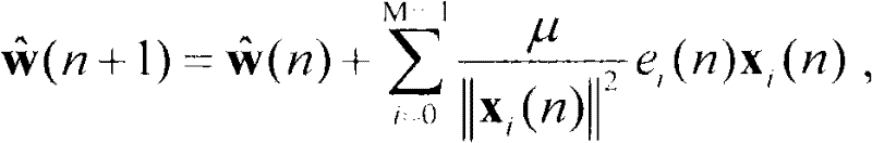 wherein mu is more than 0 and less than 2, and | xi(n) | | is for xiAnd (n) performing a modular operation.
Accordingly, the residual synthesizer 730 combines e for each subbandi(n) are added to give e (n).
Specifically, the adaptive filter 720 may specifically include: an echo estimation unit 721 and an echo filtering unit 722.
An echo estimation unit 721 for estimating the far-end input signal x for each subband according to the filter coefficients of the adaptive filter 720i(n) processing to obtain echo estimation signals of each sub-band
Echo filter unit722, for inputting near-end signals d of each sub-bandi(n) filtering out echo estimation signals of corresponding sub-bands respectively Obtaining residual signals e of each sub-bandi(n)。
The algorithm diagram corresponding to the above structure is shown in fig. 5. In addition to the above structure, another structure may be adopted, as shown in fig. 8, in this case, the apparatus may further include: a downsample processor bank 740, an upsample processor bank 750, and a synthesis filter bank 760.
A down-sampling processor bank 740 for obtaining d for each sub-band output by the first analysis filter bank 700 to the adaptive filter 720i(n) dividing d of each subbandi(n) downsampling to obtain near-end input signals d of each sub-bandi(k) And output to the adaptive filter 720.

An upsampling processor set 750 for obtaining the residual signal e of each sub-band outputted by the adaptive filter to the residual synthesizer 730i(k) E of each sub-bandi(k) Up-sampled and sent to the synthesis filter bank 760.
The synthesis filter bank 760 is configured to perform band-pass filtering on the input signals of the respective subbands and output the signals to the residual synthesizer 730.
With this structure, the adaptive filter 720 may specifically include: an echo estimation unit 721, a down-sampling unit group 723 and an echo filtering unit 722.
An echo estimation unit 721 for estimating the far-end input signal x for each subband according to the filter coefficients of the adaptive filter 720i(n) processing to obtain echo estimation signals of each sub-band
A down-sampling unit 723 for estimating the echo of each sub-band Respectively carrying out down-sampling processing to obtain echo estimation signals of each sub-band
An echo filtering unit 722 for filtering the near-end input signal d of each sub-bandi(k) Respectively filtering echo estimation signals of corresponding sub-bands Obtaining residual signals e of each sub-bandi(k)。
The algorithm diagram corresponding to the other structure is shown in fig. 6.
From the above description, it can be seen that the method and apparatus provided by the present invention divide the near-end input signal and the far-end input signal into a plurality of sub-bands, and apply NLMS algorithm to each sub-band, compared with the transform domain adaptive filter that does not apply any transform algorithm such as DCT or DFT, the amount of computation is greatly saved. Meanwhile, the far-end input signals of each sub-band are not subjected to down-sampling processing and are sent to the same adaptive filter, so that the frequency component of each sub-band signal only occupies one interval of the full frequency band, the aliasing effect cannot be generated, and the fast convergence speed can be achieved.
The above description is only for the purpose of illustrating the preferred embodiments of the present invention and is not to be construed as limiting the invention, and any modifications, equivalents, improvements and the like made within the spirit and principle of the present invention should be included in the scope of the present invention.
Claims (10)
1. A method of echo cancellation, the method comprising:
dividing the near-end input signal d (n) and the far-end input signal x (n) into M sub-band signals di(n) and xi(n), wherein n is a sampling time, i is a number of a subband signal, i is 0, 1.
The remote input signal x of each sub-bandi(n) sending the data to a unified adaptive filter without down-sampling; the adaptive filter uses x of the far-end input signal input to each subbandi(n) filtering the input near-end input signals of each sub-band to generate residual signals of each sub-band; wherein, the updating value of the filter coefficient of the self-adaptive filter is the sum of the updating values corresponding to each sub-band;
and adding the residual signals of all sub-bands to obtain residual signals e (n) after echo cancellation processing.
2. The method of claim 1, wherein the near-end input signal for each sub-band input to the adaptive filter is di(n) the adaptive filter generates a residual signal e for each subbandi(n);
Filter coefficients of the adaptive filter Wherein mu is more than 0 and less than 2, and | xi(n) | | is for xi(n) performing a modulo operation;
e of each sub-bandi(n) adding to obtain said e (n).
3. The method of claim 2, wherein the adaptive filter utilizes x of the far-end input signal input to each subbandi(n) filtering the input near-end input signals of each sub-band specifically comprises:
remote input signal x for each subband according to the filter coefficients of said adaptive filteri(n) processing to obtain echo estimation signals of each sub-band
The near-end input signal d of each sub-bandi(n) filtering out echo estimation signals of corresponding sub-bands respectivelyObtaining residual signals e of each sub-bandi(n)。
4. The method of claim 1, wherein the near-end input signal for each subband input to the adaptive filter is: near-end input signal d for each sub-bandi(n) downsampling the near-end input signal d of each sub-bandi(k) (ii) a The residual signal of each sub-band generated by the adaptive filter is ei(k);
Filter coefficients of the adaptive filter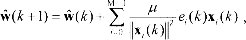 Wherein mu is more than 0 and less than 2, and | xi(k) I is to xi(k) Performing a modulus operation; k is N times of sampling time N, and N is the down-sampling extraction rate;
adding the residual signals of all sub-bands to obtain a residual signal e (n) after echo cancellation processing, wherein the residual signal e (n) is as follows: e of each sub-bandi(k) Adding the values obtained after the up-sampling and band-pass filtering treatment to obtain the e (n).
5. The method of claim 4, wherein the adaptive filter utilizes x of the far-end input signal input to each subbandi(n) filtering the input near-end input signals of each sub-band specifically comprises:
using the filter coefficients of the adaptive filter to the far-end input signal x of each sub-bandi(n) processing to obtain echo estimation signals of each sub-band
Echo estimation signal for each sub-band After down-sampling treatment to obtain
The near-end input signal d of each sub-bandi(k) Respectively filtering echo estimation signals of corresponding sub-bands Obtaining residual signals e of each sub-bandi(k)。
6. An apparatus for echo cancellation, the apparatus comprising: a first analysis filter bank, a second analysis filter bank, an adaptive filter and a residual synthesizer;
the first analysis filter bank is used for dividing the near-end input signal d (n) into M sub-band near-end input signals di(n) and output to the adaptive filter;
the second analysis filter bank is used for dividing the far-end input signal x (n) into M sub-band far-end input signals xi(n) and output to the adaptive filter; n is a sampling moment, i is a number of a sub-band signal, i is 0, 1,.. multidot.m-1, and M is a preset positive integer;
the adaptive filter is used for utilizing x of far-end input signal of each sub-bandi(n) filtering the input near-end input signals of each sub-band to generate residual signals of each sub-band, and outputting the residual signals to the residual synthesizer; wherein, the updating value of the filter coefficient of the self-adaptive filter is the sum of the updating values corresponding to each sub-band;
and the residual error synthesizer is used for adding the input residual error signals of all sub-bands to obtain a residual error signal e (n) after echo cancellation processing.
7. The apparatus of claim 6, wherein the near-end input signal for each sub-band input to the adaptive filter is di(n) the adaptive filter generates a residual signal e for each subbandi(n);
Filter coefficients of the adaptive filter Wherein mu is more than 0 and less than 2, and | xi(n) | | is for xi(n) performing a modulo operation;
the residual synthesizer converts e of each sub-bandi(n) adding to obtain said e (n).
8. The apparatus of claim 7, wherein the adaptive filter comprises:
an echo estimation unit for estimating the far-end input signal x of each sub-band according to the filter coefficient of the adaptive filteri(n) processing to obtain echo estimation signals of each sub-band
An echo filtering unit for filtering the near-end input signal d of each sub-bandi(n) filtering out echo estimation signals of corresponding sub-bands respectively Obtaining residual signals e of each sub-bandi(n)。
9. The apparatus of claim 6, further comprising: a down-sampling processor bank, an up-sampling processor bank and a synthesis filter bank;
the down-sampling processor group is used for acquiring d of each sub-band output to the adaptive filter by the first analysis filter groupi(n) dividing d of each subbandi(n) downsampling to obtain near-end input signals d of each sub-bandi(k) And output to the adaptive filter;
the adaptive filter uses x of the far-end input signal input to each sub-bandi(n) near-end input signals d for each input subbandi(k) After filtering, generating residual signals e of each sub-bandi(k) Outputting the residual error to the residual error synthesizer; filter coefficients of the adaptive filter Wherein mu is more than 0 and less than 2, and | xi(k) I is to xi(k) Performing a modulus operation; k is N times of sampling time N, and N is the down-sampling extraction rate;
an upsampling processor set for obtaining a residual signal e of each sub-band output by the adaptive filter to the residual synthesizeri(k) E of each sub-bandi(k) Performing upsampling and sending the upsampled data to a synthesis filter bank;
and the synthesis filter bank is used for performing band-pass filtering processing on the input signals of all the sub-bands and outputting the processed signals to the residual error synthesizer.
10. The apparatus of claim 9, wherein the adaptive filter comprises:
an echo estimation unit for estimating the far-end input signal x of each sub-band according to the filter coefficient of the adaptive filteri(n) processing to obtain echo estimation signals of each sub-band
A down-sampling unit group for estimating the echo of each sub-band Respectively carrying out down-sampling processing to obtain echo estimation signals of each sub-band
An echo filtering unit for filtering the near-end input signal d of each sub-bandi(k) Respectively filtering echo estimation signals of corresponding sub-bands Obtaining residual signals e of each sub-bandi(k)。
Priority Applications (1)
| Application Number | Priority Date | Filing Date | Title |
|---|---|---|---|
| CN201010263632.9A CN102377454B (en) | 2010-08-25 | 2010-08-25 | Method and device for echo cancellation |
Applications Claiming Priority (1)
| Application Number | Priority Date | Filing Date | Title |
|---|---|---|---|
| CN201010263632.9A CN102377454B (en) | 2010-08-25 | 2010-08-25 | Method and device for echo cancellation |
Publications (2)
| Publication Number | Publication Date |
|---|---|
| CN102377454A true CN102377454A (en) | 2012-03-14 |
| CN102377454B CN102377454B (en) | 2014-09-17 |
Family
ID=45795527
Family Applications (1)
| Application Number | Title | Priority Date | Filing Date |
|---|---|---|---|
| CN201010263632.9A Active CN102377454B (en) | 2010-08-25 | 2010-08-25 | Method and device for echo cancellation |
Country Status (1)
| Country | Link |
|---|---|
| CN (1) | CN102377454B (en) |
Cited By (8)
| Publication number | Priority date | Publication date | Assignee | Title |
|---|---|---|---|---|
| CN104159177A (en) * | 2014-07-16 | 2014-11-19 | 浙江航天长峰科技发展有限公司 | Audio recording system and method based on screencast |
| CN104735273A (en) * | 2014-12-26 | 2015-06-24 | 深圳市微纳集成电路与系统应用研究院 | Communication system and echo cancellation method and module thereof |
| CN105070296A (en) * | 2015-07-10 | 2015-11-18 | 西南交通大学 | Active factor set membership proportional sub band self-adaption echo cancellation method |
| CN105957536A (en) * | 2016-04-25 | 2016-09-21 | 南京奇音石信息技术有限公司 | Frequency domain echo eliminating method based on channel aggregation degree |
| CN106128471A (en) * | 2016-08-26 | 2016-11-16 | 西南交通大学 | A kind of contraction variable step subband acoustic echo removing method |
| CN104427144B (en) * | 2013-09-11 | 2017-06-13 | 联芯科技有限公司 | A kind of linear echo removing method and its device |
| CN111798827A (en) * | 2020-07-07 | 2020-10-20 | 上海立可芯半导体科技有限公司 | Echo cancellation method, apparatus, system and computer readable medium |
| US11151976B2 (en) | 2017-10-19 | 2021-10-19 | Zhejiang Dahua Technology Co., Ltd. | Methods and systems for operating a signal filter device |
Citations (3)
| Publication number | Priority date | Publication date | Assignee | Title |
|---|---|---|---|---|
| WO2000016497A1 (en) * | 1998-09-17 | 2000-03-23 | Ericsson Inc. | Echo canceler adaptive filter optimization |
| CN1668058A (en) * | 2005-02-21 | 2005-09-14 | 南望信息产业集团有限公司 | Recursive least square difference based subband echo canceller |
| CN101227537A (en) * | 2007-01-19 | 2008-07-23 | 中兴通讯股份有限公司 | A Broadband Acoustic Echo Cancellation Method |
-
2010
- 2010-08-25 CN CN201010263632.9A patent/CN102377454B/en active Active
Patent Citations (3)
| Publication number | Priority date | Publication date | Assignee | Title |
|---|---|---|---|---|
| WO2000016497A1 (en) * | 1998-09-17 | 2000-03-23 | Ericsson Inc. | Echo canceler adaptive filter optimization |
| CN1668058A (en) * | 2005-02-21 | 2005-09-14 | 南望信息产业集团有限公司 | Recursive least square difference based subband echo canceller |
| CN101227537A (en) * | 2007-01-19 | 2008-07-23 | 中兴通讯股份有限公司 | A Broadband Acoustic Echo Cancellation Method |
Non-Patent Citations (1)
| Title |
|---|
| JULIE E. GREENBERG: "《Modified LMS Algorithms for speech Processing with an Adaptive Noise Canceller》", 《IEEE TRANSACTIONS OF SPEECH AND AUDIO PROCESSING》 * |
Cited By (10)
| Publication number | Priority date | Publication date | Assignee | Title |
|---|---|---|---|---|
| CN104427144B (en) * | 2013-09-11 | 2017-06-13 | 联芯科技有限公司 | A kind of linear echo removing method and its device |
| CN104159177A (en) * | 2014-07-16 | 2014-11-19 | 浙江航天长峰科技发展有限公司 | Audio recording system and method based on screencast |
| CN104735273A (en) * | 2014-12-26 | 2015-06-24 | 深圳市微纳集成电路与系统应用研究院 | Communication system and echo cancellation method and module thereof |
| CN105070296A (en) * | 2015-07-10 | 2015-11-18 | 西南交通大学 | Active factor set membership proportional sub band self-adaption echo cancellation method |
| CN105957536A (en) * | 2016-04-25 | 2016-09-21 | 南京奇音石信息技术有限公司 | Frequency domain echo eliminating method based on channel aggregation degree |
| CN105957536B (en) * | 2016-04-25 | 2019-11-12 | 深圳永顺智信息科技有限公司 | Based on channel degree of polymerization frequency domain echo cancel method |
| CN106128471A (en) * | 2016-08-26 | 2016-11-16 | 西南交通大学 | A kind of contraction variable step subband acoustic echo removing method |
| CN106128471B (en) * | 2016-08-26 | 2019-05-17 | 西南交通大学 | A kind of contraction variable step subband acoustic echo removing method |
| US11151976B2 (en) | 2017-10-19 | 2021-10-19 | Zhejiang Dahua Technology Co., Ltd. | Methods and systems for operating a signal filter device |
| CN111798827A (en) * | 2020-07-07 | 2020-10-20 | 上海立可芯半导体科技有限公司 | Echo cancellation method, apparatus, system and computer readable medium |
Also Published As
| Publication number | Publication date |
|---|---|
| CN102377454B (en) | 2014-09-17 |
Similar Documents
| Publication | Publication Date | Title |
|---|---|---|
| CN102377454B (en) | Method and device for echo cancellation | |
| JP5221117B2 (en) | Low complexity echo compensation | |
| US10038795B2 (en) | Robust acoustic echo cancellation for loosely paired devices based on semi-blind multichannel demixing | |
| JP5122879B2 (en) | Partitioned fast convolution in time and frequency domain | |
| JP3177562B2 (en) | Low delay subband adaptive filter device | |
| US6487574B1 (en) | System and method for producing modulated complex lapped transforms | |
| CN101227537B (en) | A Broadband Acoustic Echo Cancellation Method | |
| CN102387272B (en) | Restraining method for residual echo in echo cancellation system | |
| JP2014502074A (en) | Echo suppression including modeling of late reverberation components | |
| CN101833949A (en) | An Active Noise Control Method for Noise Reduction | |
| JPH08213940A (en) | Signal processor and signal processing method | |
| EP2562751B1 (en) | Temporal interpolation of adjacent spectra | |
| US9837098B2 (en) | Reduced-delay subband signal processing system and method | |
| CN104427144B (en) | A kind of linear echo removing method and its device | |
| CN106601266A (en) | Echo cancellation method, device and system | |
| CN107409255A (en) | The ADAPTIVE MIXED of subband signal | |
| CN106210368A (en) | The method and apparatus eliminating multiple channel acousto echo | |
| EP1638079A2 (en) | Method and system for active noise cancellation | |
| JP2003501963A (en) | Symmetric subband acoustic echo cancellation | |
| CN109451398B (en) | Acoustic feedback cancellation apparatus, acoustic feedback cancellation method, and audio processing system | |
| CN113347536B (en) | Acoustic feedback suppression algorithm based on linear prediction and sub-band adaptive filtering | |
| EP1879292B1 (en) | Partitioned fast convolution | |
| Löllmann et al. | Generalized filter-bank equalizer for noise reduction with reduced signal delay. | |
| Krini et al. | Method for temporal interpolation of short-term spectra and its application to adaptive system identification | |
| Duplessis-Beaulieu et al. | Fast convolutive blind speech separation via subband adaptation |
Legal Events
| Date | Code | Title | Description |
|---|---|---|---|
| C06 | Publication | ||
| PB01 | Publication | ||
| C10 | Entry into substantive examination | ||
| SE01 | Entry into force of request for substantive examination | ||
| C14 | Grant of patent or utility model | ||
| GR01 | Patent grant | ||
| CP03 | Change of name, title or address | ||
| CP03 | Change of name, title or address |
Address after: 310052 Binjiang District Changhe Road, Zhejiang, China, No. 466, No. Patentee after: Xinhua three Technology Co., Ltd. Address before: 310053 Hangzhou hi tech Industrial Development Zone, Zhejiang province science and Technology Industrial Park, No. 310 and No. six road, HUAWEI, Hangzhou production base Patentee before: Huasan Communication Technology Co., Ltd. |