CN102331061A - Energy-saving type air conditioning apparatus for PC room, and method thereof - Google Patents
Energy-saving type air conditioning apparatus for PC room, and method thereof Download PDFInfo
- Publication number
- CN102331061A CN102331061A CN2011101486390A CN201110148639A CN102331061A CN 102331061 A CN102331061 A CN 102331061A CN 2011101486390 A CN2011101486390 A CN 2011101486390A CN 201110148639 A CN201110148639 A CN 201110148639A CN 102331061 A CN102331061 A CN 102331061A
- Authority
- CN
- China
- Prior art keywords
- air
- room
- cabinet
- energy
- indoor
- Prior art date
- Legal status (The legal status is an assumption and is not a legal conclusion. Google has not performed a legal analysis and makes no representation as to the accuracy of the status listed.)
- Pending
Links
- 238000004378 air conditioning Methods 0.000 title claims abstract description 55
- 238000000034 method Methods 0.000 title claims description 19
- 239000000428 dust Substances 0.000 claims description 12
- 238000006243 chemical reaction Methods 0.000 description 10
- 238000010438 heat treatment Methods 0.000 description 10
- 230000001105 regulatory effect Effects 0.000 description 10
- 238000005259 measurement Methods 0.000 description 8
- 238000005265 energy consumption Methods 0.000 description 6
- 238000004891 communication Methods 0.000 description 5
- 238000009529 body temperature measurement Methods 0.000 description 4
- 238000004140 cleaning Methods 0.000 description 4
- 230000001276 controlling effect Effects 0.000 description 3
- 238000001514 detection method Methods 0.000 description 3
- 238000012423 maintenance Methods 0.000 description 3
- 238000010276 construction Methods 0.000 description 2
- 238000010586 diagram Methods 0.000 description 2
- 230000005540 biological transmission Effects 0.000 description 1
- 238000007664 blowing Methods 0.000 description 1
- 230000005465 channeling Effects 0.000 description 1
- 238000013461 design Methods 0.000 description 1
- 238000007599 discharging Methods 0.000 description 1
- 239000006185 dispersion Substances 0.000 description 1
- 230000000694 effects Effects 0.000 description 1
- 238000004134 energy conservation Methods 0.000 description 1
- 238000005516 engineering process Methods 0.000 description 1
- 230000006870 function Effects 0.000 description 1
- 238000009499 grossing Methods 0.000 description 1
- 238000007726 management method Methods 0.000 description 1
- 238000012986 modification Methods 0.000 description 1
- 230000004048 modification Effects 0.000 description 1
- 238000012546 transfer Methods 0.000 description 1
Images


Classifications
-
- F—MECHANICAL ENGINEERING; LIGHTING; HEATING; WEAPONS; BLASTING
- F24—HEATING; RANGES; VENTILATING
- F24F—AIR-CONDITIONING; AIR-HUMIDIFICATION; VENTILATION; USE OF AIR CURRENTS FOR SCREENING
- F24F11/00—Control or safety arrangements
- F24F11/0001—Control or safety arrangements for ventilation
-
- F—MECHANICAL ENGINEERING; LIGHTING; HEATING; WEAPONS; BLASTING
- F24—HEATING; RANGES; VENTILATING
- F24F—AIR-CONDITIONING; AIR-HUMIDIFICATION; VENTILATION; USE OF AIR CURRENTS FOR SCREENING
- F24F13/00—Details common to, or for air-conditioning, air-humidification, ventilation or use of air currents for screening
- F24F13/08—Air-flow control members, e.g. louvres, grilles, flaps or guide plates
- F24F13/10—Air-flow control members, e.g. louvres, grilles, flaps or guide plates movable, e.g. dampers
-
- F—MECHANICAL ENGINEERING; LIGHTING; HEATING; WEAPONS; BLASTING
- F24—HEATING; RANGES; VENTILATING
- F24F—AIR-CONDITIONING; AIR-HUMIDIFICATION; VENTILATION; USE OF AIR CURRENTS FOR SCREENING
- F24F13/00—Details common to, or for air-conditioning, air-humidification, ventilation or use of air currents for screening
- F24F13/28—Arrangement or mounting of filters
-
- F—MECHANICAL ENGINEERING; LIGHTING; HEATING; WEAPONS; BLASTING
- F24—HEATING; RANGES; VENTILATING
- F24F—AIR-CONDITIONING; AIR-HUMIDIFICATION; VENTILATION; USE OF AIR CURRENTS FOR SCREENING
- F24F7/00—Ventilation
- F24F7/04—Ventilation with ducting systems, e.g. by double walls; with natural circulation
- F24F7/06—Ventilation with ducting systems, e.g. by double walls; with natural circulation with forced air circulation, e.g. by fan positioning of a ventilator in or against a conduit
- F24F7/08—Ventilation with ducting systems, e.g. by double walls; with natural circulation with forced air circulation, e.g. by fan positioning of a ventilator in or against a conduit with separate ducts for supplied and exhausted air with provisions for reversal of the input and output systems
-
- F—MECHANICAL ENGINEERING; LIGHTING; HEATING; WEAPONS; BLASTING
- F24—HEATING; RANGES; VENTILATING
- F24F—AIR-CONDITIONING; AIR-HUMIDIFICATION; VENTILATION; USE OF AIR CURRENTS FOR SCREENING
- F24F2110/00—Control inputs relating to air properties
- F24F2110/10—Temperature
Landscapes
- Engineering & Computer Science (AREA)
- Chemical & Material Sciences (AREA)
- Combustion & Propulsion (AREA)
- Mechanical Engineering (AREA)
- General Engineering & Computer Science (AREA)
- Air Conditioning Control Device (AREA)
Abstract
Disclosed is an energy-saving type air conditioning apparatus for a PC room. The apparatus comprises a PC cabinet, a suction unit and an exhaust unit, wherein the PC cabinet comprises a plurality of main hosts; the air sucked into the PC cabinet is heated by the heats generated by the PC cabinet; the suction unit sucks the indoor air or the outdoor air, and provides the indoor air or the outdoor air to the PC cabinet; and the exhaust unit sucks the air heated by the PC cabinet, then exhausts the air inside or outside of the PC room.
Description
The cross reference of related application
The rights and interests that the korean patent application that this application requires to submit on June 3rd, 2010 is 10-2010-0052473 number are herein incorporated its full content in the application hereby by reference.
Technical field
The application relates generally to be used for the energy-saving air conditioning equipment and the method in PC room; And more specifically; Relate to the energy-saving air conditioning equipment that is used for the PC room below a kind of and use the energy-saving air control method of this equipment; This energy-saving air conditioning equipment depends on controls the heat that is generated by the PC main frame (body) from the PC room season and the air that heats efficiently, makes the minimise power consumption when this PC room of management thus.
Background technology
The PC room is the space that is used to use PC (personal computer), and is known as the Internet bar in the U.S..Up to date, the cost of energy in PC room does not cause too many attention as yet.Yet because the increase of PC power consumption and power cost, cost of energy has become one of the key factor that when design PC room, must consider.
It approximately is 50% of this total power consumption in PC room that typical PC room energy consumption is analyzed the power consumption that has disclosed the IT device (for example, PC main frame, monitor etc.) that is arranged in the PC room.The power consumption that has disclosed the air that is used for reply (treat) PC room approximately is 37% of this total power consumption in PC room.
In order to implement the optimum air handling system that is used for the PC room, it is very important forming the path of blowing efficiently.In addition, it also is important using the energy of minimum number to come to remove as much as possible the heat that the IT device in the PC room generated.
Yet existing P C machine room can not be disposed the heat that is generated from the PC main frame effectively.Specifically, in current PC room, because each PC main frame lays respectively on each user's desk, so can not control the heat that the PC main frame is generated efficiently.
Thereby the heat that operation generated of PC main frame directly is dispersed in the PC room.Thus, the temperature in the PC room increases, and the feasible PC room is freezed needs high energy consumption.
Summary of the invention
Correspondingly; Made the present invention under the situation of the above problem that in keeping it in mind prior art, has occurred; And the object of the present invention is to provide a kind of energy-saving air control method that is used for the energy-saving air conditioning equipment in PC room and uses this equipment; This energy-saving air conditioning equipment comprises wherein installs the also PC cabinet of overall maintenance PC main frame; And this energy-saving air conditioning equipment is configured, makes and can depend on and season the heat selective ground that is generated from the PC cabinet is used for the air in PC room is regulated, make thus when managing this PC room, be used for to air regulate energy consumption minimized.
In order to realize above purpose, the invention provides a kind of energy-saving air conditioning equipment that is used for the PC room, comprising: the PC cabinet, wherein comprise a plurality of PC main frames, the air that wherein is pumped in the PC cabinet is heated by the heat that is generated from the PC main frame; Suction unit in the suction chamber or outdoor air, and is fed to the indoor or outdoors air in the PC cabinet; And exhaust unit, draw the air that the PC cabinet is heated, and be discharged in the PC room this air or outside the PC room.
This suction unit can comprise: indoor air intake duct is connected to the ceiling panel (ceiling panel) in PC room; Outdoor air intake duct is connected to the exterior wall in PC room; Induced-draught fan comes in the suction chamber or outdoor air through indoor air intake duct or outdoor air intake duct; And air-breathing tube connector, to the PC cabinet indoor or outdoors air from induced-draught fan is provided.
This induced-draught fan can comprise: indoor/outdoor air conversion valve, depend on that user's selection opens or closes indoor air intake duct, and depend on that user's selection opens or closes outdoor air intake duct.
This suction unit can comprise: filter, from the indoor or outdoors air, remove fine dust.
This exhaust unit can comprise: exhaust blower, and draw the air that the PC cabinet is heated, and the air that the PC cabinet is heated is sent in the exhaust connection that is connected in exhaust blower one side; And bypass damper, being connected to exhaust blower through exhaust connection, this bypass damper will be discharged into through the air that exhaust connection is extracted in the PC room or outside the PC room.
This energy-saving air conditioning equipment can also comprise: temperature controller; Measure the temperature in the PC room; And to bypass damper output control signal; Control the opening degree of bypass damper with the temperature in the PC room that depends on measurement, wherein this bypass damper can depend on that the control signal that transmits from temperature controller adjusts opening degree, makes and will optionally be discharged into the PC room or outside the PC room from the air that exhaust connection is extracted.
This bypass damper can comprise: bypass duct will be divided into indoor circulation air and outside drain air through the air that exhaust connection is extracted; Circulation pipe is fed to the indoor circulation air in the PC room; Delivery pipe is discharged into the outside drain air outside the PC room; This circulation pipe is closed or opened to circulating current control valve; And exhaust jet stream control valve, close or open this delivery pipe.
This energy-saving air conditioning equipment can also comprise: temperature controller; Measure the temperature in the PC room; And output control signal; The opening degree of controlling circulating current control valve with the temperature in the PC room that is used for depending on measurement and exhaust jet stream are controlled the opening degree of valve; Wherein this circulating current control valve and this exhaust jet stream control valve can depend on that the control signal that transmits from temperature controller adjusts opening degree, make and will optionally be discharged in the PC room or outside the PC room through the air that exhaust connection is extracted.
Preferably, the air capacity per hour drawn of suction unit can equal the air capacity that exhaust unit is per hour drawn.
In addition; Air inlet and gas outlet can be formed in the end face of PC cabinet, and the air inlet guide plate can give vent to anger that guide plate tilts with predetermined angle and this mode that is mutually symmetrical and being placed on respectively under air inlet and the gas outlet according to this air inlet guide plate and this with the guide plate of giving vent to anger.
In order to realize above purpose; The invention provides a kind of energy-saving air control method that is used for the PC room; Comprise: use in the suction unit suction chamber or outdoor air, and will be fed to from the indoor or outdoors air of this suction unit in the PC cabinet that wherein comprises a plurality of PC main frames; The heat that will be generated from the PC main frame of PC cabinet is delivered to from this suction unit and is fed to the air the PC cabinet; And use exhaust unit to draw the air that the PC cabinet is heated, and will be discharged in the PC room or outside the PC room from the hot-air that adds of this exhaust unit from the PC cabinet.
This energy-saving air control method can also comprise: use filter that suction unit institute inhaled air is filtered, from this air, to remove fine dust.
In the said use suction unit suction chamber or the step of outdoor air can comprise: the outdoor air intake duct of the indoor air intake duct of the ceiling panel through being connected to the PC room or the exterior wall through being connected to the PC room, come in the suction chamber or outdoor air.
This energy-saving air control method can also comprise: the serviceability temperature controller is measured the temperature in the PC room, and the output control signal, controls exhaust unit to be used to depend on the computer room temperature of measurement; And depend on that the air that the PC cabinet heated from the control signal of temperature controller output is discharged into the PC room or outside the PC room from exhaust unit.
Preferably, the air capacity per hour drawn of suction unit can equal the air capacity that exhaust unit is per hour drawn.
In addition; Air inlet and gas outlet can be formed in the end face of PC cabinet, and the air inlet guide plate can give vent to anger that guide plate tilts with predetermined angle and this mode that is mutually symmetrical and being placed on respectively under air inlet and the gas outlet according to this air inlet guide plate and this with the guide plate of giving vent to anger.
The invention provides following effect.
In the PC cabinet, be installed in the PC main frame that provides in the PC room, make and integrally to safeguard them.Can depend on the computer room temperature of measurement, add hot-air and optionally use from what the PC cabinet was generated, so that the air in the machine room is regulated, thereby can so that be used for to the air in PC room regulate energy consumption minimized.That is, when the temperature in the machine room is relatively low, will be fed to the PC room, and make the air in the machine room is circulated and regulates by the air that heats from heat that the PC main frame generated.When the temperature in the machine room when higher, will by from heat that the PC main frame generated and the air that heats directly be discharged into outside the machine room.Therefore, can be so that be used for air conditioning energy consumption minimized in PC room.
Description of drawings
According to the following detailed description that combines accompanying drawing to carry out, will be expressly understood more of the present invention above with other purpose, feature and advantage, wherein:
Fig. 1 is the view that illustrates the PC cabinet that the energy-saving air conditioning equipment being used for the PC room according to the embodiment of the invention uses;
Fig. 2 is the profile of internal structure that illustrates the PC cabinet of Fig. 1;
The view of the structure at the top of the PC cabinet of Fig. 3 is shown in detail in figs Fig. 2;
Fig. 4 is the view that illustrates according to the energy-saving air conditioning equipment of first embodiment of the invention;
Fig. 5 is the view that illustrates according to the energy-saving air conditioning equipment of second embodiment of the invention;
Fig. 6 is the view that illustrates according to the energy-saving air conditioning equipment of third embodiment of the invention;
The block diagram of the structure of the temperature controller of the equipment of Fig. 7 is shown in detail in figs Fig. 6;
Fig. 8 is to use the flow chart of the method that energy-saving air conditioning equipment according to the present invention comes the air in the PC room is regulated;
Fig. 9 is to use the flow chart of the method that the temperature controller of Fig. 6 comes the temperature in the PC room is controlled; And
Figure 10 shows the view that provides according to the PC room of energy-saving air conditioning equipment of the present invention.
The specific embodiment
If in specification, the detailed description of known function or configuration possibly unnecessarily make main idea of the present invention fuzzy, then will omit this detailed description.
Should the term and the word that in this specification and accompanying claims, use be interpreted as those implications that have their common implications or in dictionary, find out limitedly; But should can suitably define the notion of term so that describe the principle of his or her invention best based on the inventor, it is interpreted as has the implication that is suitable for technical spirit of the present invention.
Should be noted that in different drawings, use identical Reference numeral to specify same or analogous assembly as much as possible.
Hereinafter, will describe the present invention in detail with reference to accompanying drawing.Be used for the energy-saving air conditioning equipment in PC room and using in the following description of the method that this equipment comes the air of machine room is regulated according to of the present invention, hypothesis is being operated in a plurality of PC main frames of installing in the PC cabinet and their generate heat.
Fig. 1 is the view that illustrates the PC cabinet that the energy-saving air conditioning equipment being used for the PC room according to the embodiment of the invention uses.Fig. 2 is the profile of internal structure that illustrates the PC cabinet of Fig. 1.The view of the structure at the top of the PC cabinet of Fig. 3 is shown in detail in figs Fig. 2.
With reference to figure 1, a plurality of PC main frames 50 have been installed in PC cabinet 100.The number of the PC main frame of in PC cabinet 100, installing 50 can depend on size and the structure of PC cabinet 100 and change.
In the present embodiment, come in PC cabinet 100, to install PC main frame 50 according to this mode that 50 1 in PC main frame is stacked on another top.Has the structure that is used for stably supporting PC main frame 50 in the PC cabinet 100, although do not illustrate this structure in the drawings.
Pass the end face of PC cabinet 100 and form two holes.One of said two holes are air inlets 101, and it is connected to air-breathing tube connector 127, make through air-breathing tube connector 127 and air inlet 101 outdoor air to be fed in the PC cabinet 100.Another hole is gas outlet 102, and the air of heating is discharged into outside the PC cabinet 100 through this gas outlet 102.
With reference to figure 2, be fed to the inside that outdoor air the PC cabinet 100 cycles through PC cabinet 100 from air inlet 101, and by the heat heating that is generated from PC main frame 50.The air of heating is discharged into outside the PC cabinet 100 through gas outlet 102.Preferably, except air inlet 101 and gas outlet 102, the hole that in PC cabinet 100, is formed for taking a breath is so that transfer heat to the air that is pumped in the PC cabinet 100 more effectively.To explain the operation that outdoor air is fed in the PC cabinet 100 and before the air with heating is discharged into outside the PC cabinet 100, draws the air that PC cabinet 100 heated after a while in further detail here.
Therebetween, under air inlet 101 and gas outlet 102, place air inlet guide plate 115 respectively and give vent to anger guide plate 116, the said air inlet guide plate 115 and the angle inclination of guide plate 116 of giving vent to anger, and be mutually symmetrical (with reference to figure 2 and 3) to be scheduled to.
Air inlet guide plate 115 is used for the air-flow channeling conduct with the guide plate 116 of giving vent to anger; Make the outdoor air that is fed to the PC cabinet 100 from air inlet 101 to reach surface smoothing flows thereafter, and be discharged into smoothly outside the PC cabinet 100 through gas outlet 102 then along the front surface of PC main frame.In other words, air inlet guide plate 115 makes air possibly when absorbing heat, cycle through the inside of PC cabinet 100 smoothly with the guide plate 116 of giving vent to anger.
Fig. 4 is the view that illustrates according to the energy-saving air conditioning equipment of first embodiment of the invention.
With reference to figure 4, energy-saving air conditioning equipment according to the present invention comprises PC cabinet, suction unit, exhaust unit and temperature controller.The PC cabinet wherein comprises a plurality of PC main frames, and will be delivered to the air that is pumped into the PC cabinet from the heat that the PC main frame is generated.Suction unit is drawn the machine room air, and it is fed in the PC cabinet.Exhaust unit is drawn the air that the PC cabinet is heated, and with it be discharged in the machine room or outside.Temperature controller is controlled exhaust unit, make the air optionally the PC cabinet is heated be discharged in the machine room or outside.
At length, suction unit comprises: indoor air intake duct 122, and it is connected to the ceiling panel (that is the ceiling panel in PC room) of machine room; Induced-draught fan 125, it draws room air through indoor air intake duct 122; With air-breathing tube connector 127, it will be fed in the PC cabinet 100 by the room air that induced-draught fan 125 is drawn.
Preferably, filter 120a is provided in correspondence one end of the indoor air intake duct 122 that is connected to ceiling panel.Remove fine dust etc. in the room air of filter 120a from be drawn into indoor air intake duct 122.In other words; Filter 122a filters the room air of being drawn by the operation of induced-draught fan 125; So that the air of cleaning is fed in the rack 100, make that can prevent PC main frame 50 comprises fine dust and break down because be fed to room air in the rack 100.
Be pumped into the heat heating that the air in the PC cabinet 100 is generated by PC main frame 50 through air-breathing tube connector 127.Exhaust unit is drawn the air of heating in PC cabinet 100, and then it is discharged in the machine room or outside.
For this reason, exhaust unit comprises: exhaust blower 135, and it draws the air that PC cabinet 100 is heated, and the air of heating is sent to the exhaust connection 137 that is coupled to exhaust blower 135 1 sides; And bypass damper, it is connected to exhaust blower 135 through exhaust connection 137, and with the air of heating from exhaust connection 137 be discharged into the machine room or outside.
Bypass damper comprises bypass duct 140, circulation pipe 153 and 157, blast pipe 142 and 147, circulating current control valve 155 and exhaust jet stream control valve 145.Bypass duct 140 will be divided into indoor circulation air and outside drain air from the hot-air that adds that exhaust connection 137 is extracted.The indoor circulation air that circulation pipe 153 and 157 will separate from bypass duct 140 is fed to the machine room.The outside drain air that blast pipe 142 and 147 will separate from bypass duct 140 is discharged into outside the machine room.Circulation pipe 153 and 157 are closed or opened to circulating current control valve 155. Blast pipe 142 and 147 are closed or opened to exhaust jet stream control valve 145.
The structure of bypass damper is not limited to above-mentioned structure.In other words, bypass damper can have any structure, if it can be optionally with the air from exhaust connection 137 send in the machine room or outside.
Expansion cap (extension cap) 160 is provided on the respective ends of circulation pipe 157, makes the air dispersion that can be easily will pass circulation pipe 157 through expansion cap 160 in machine room.
In addition, pipe cap (duct cap) 150 is provided on the respective ends of blast pipe 147.Pipe cap 150 prevents that foreign matter from getting into blast pipe 147.
The temperature that temperature controller 200 is measured in the machine room; And come to control the opening degree of circulating current control valve 155 and exhaust jet stream control valve 145 with the temperature in the machine room that depends on measurement to circulating current control valve 155 and exhaust jet stream control valve 145 output control signals through communication line 170a and 170b.
In addition, circulating current control valve 155 is controlled in the valve 145 with exhaust jet stream and is had air flow control panel.Thereby, depend on the control signal that transmits from temperature controller 200, the degree that air flow control panel is opened changes, make the air that transmits from exhaust connection 137 optionally be discharged into the machine room or outside.In order to implement this structure, each in circulating current control valve 155 and the exhaust jet stream control valve 145 has motor or actuator, and it depends on that control signal changes the degree that air flow control panel is opened.
For example, in the winter that the temperature in machine room is lower, temperature controller 200 cuts out blast pipe 142 and 147, and only opens circulation pipe 153 and 157, and the air that makes PC cabinet 100 heated is used for the air of machine room is regulated.
In contrast, the temperature in machine room is than higher summer, and temperature controller 200 cuts out circulation pipe 153 and 157, and only opens blast pipe 142 and 147, and the air that makes PC cabinet 100 heated directly is discharged into outside the machine room.
To explain the structure and the operation of temperature controller 200 here, after a while with reference to figure 7 and 9.
Therebetween, the indoor or outdoors air capacity per hour drawn of suction unit is per hour identical from the air capacity that the PC cabinet is drawn with exhaust unit.In other words, the output of induced-draught fan 125 is identical with the output of exhaust blower 135.
Fig. 5 is the view that illustrates according to the energy-saving air conditioning equipment of second embodiment of the invention.
With compare textural distinct according to the suction unit of the energy-saving air conditioning equipment of second embodiment with reference to figure 4 described energy-saving air conditioning equipments according to first embodiment.The remainder of the ordinary construction of the energy-saving air conditioning equipment of second embodiment is identical with the maintenance among first embodiment.Thereby in the following description, avoiding repeating this explanation, and the above explanation of Fig. 4 will substitute it with the explanation of omitting same configuration.Those skilled in the art will easily understand this substituting.
With reference to figure 5, comprise according to the suction unit of the energy-saving air conditioning equipment of second embodiment: outdoor air intake duct 123, it is connected to the exterior wall (that is the exterior wall in PC room) of machine room; Induced-draught fan 125, it is the suction chamber outer air through outdoor air intake duct 123; With air-breathing tube connector 127, it will be fed in the PC cabinet 100 by the outdoor air that induced-draught fan 125 is drawn.
Preferably, filter 120b is provided in the respective ends of the outdoor air intake duct 123 that is connected to exterior wall.Remove fine dust etc. in the outdoor air of filter 120b from be drawn into outdoor air intake duct 123.In other words; Filter 122b filters the outdoor air of being drawn by the operation of induced-draught fan 125; So that the air of cleaning is fed in the rack 100, make to prevent that the fine dust that comprises in the outdoor air in being fed to PC cabinet 100 from making PC main frame 50 break down.
Fig. 6 is the view that illustrates according to the energy-saving air conditioning equipment of third embodiment of the invention.
According to the energy-saving air conditioning equipment of the 3rd embodiment with between with reference to figure 4 described energy-saving air conditioning equipments according to first embodiment, the structure of suction unit is different.Keep identical among the remainder of the ordinary construction of the energy-saving air conditioning equipment of the 3rd embodiment and first embodiment.Thereby in the following description, avoiding repeating this explanation, and the above explanation of Fig. 4 will substitute it with the explanation of omitting same configuration.Those skilled in the art will easily understand this substituting.
With reference to figure 6, comprise according to the suction unit of the energy-saving air conditioning equipment of the 3rd embodiment: indoor air intake duct 122, it is connected to the ceiling panel (that is the ceiling panel in PC room) of machine room; Outdoor air intake duct 123, it is connected to the exterior wall (that is the exterior wall in PC room) of machine room; Induced-draught fan 128, they are in indoor air intake duct 122 and outdoor air intake duct 123 suction chamber and outdoor air; With air-breathing tube connector 127, it will be fed in the PC cabinet 100 by the indoor or outdoors air that induced-draught fan 125 is drawn.In the 3rd embodiment, induced-draught fan 128 comprises indoor/outdoor air conversion valve (not shown), and it depends on that user's selection closes or open indoor air intake duct 122, and closes or open outdoor air intake duct 123.
Indoor/outdoor air conversion valve is connected to temperature controller 200 through communication line 170c, and depends on the opening degree of controlling the air flow control panel that wherein provides from the control signal of temperature controller 200 transmission.In order to implement this structure, indoor/outdoor air conversion valve has motor or actuator, and it depends on that control signal changes the degree that air flow control panel is opened.At length, when from temperature controller 200 input outdoor air mode signals, this air flow control panel of indoor/outdoor air conversion valve control is with air intake duct in the close chamber 122 and open outdoor air intake duct 123, makes that induced-draught fan 128 can the suction chamber outer air.In contrast, when from temperature controller 200 input room air mode signals, this air flow control panel of indoor/outdoor air conversion valve control is with air intake duct outside the close chamber 123 and open indoor air intake duct 122, makes induced-draught fan 128 can suck room air.
Because above-mentioned structure; The user can select to use the air conditioning pattern (room air pattern) of room air or the air conditioning pattern (outdoor air pattern) of use outdoor air for example through using selection or the load button that on temperature controller 200, provides.
Therebetween; Preferably; On the respective ends of respective ends that filter 120a and 120b are provided at (being connected to ceiling panel) indoor air intake duct 122 respectively and (being connected to exterior wall) outdoor air intake duct 123, make and from the air of being drawn, remove fine dust etc. through filter 120a and 120b.
In other words; Filter 122a filters the room air of being drawn by the operation of induced-draught fan 125; So that the air of cleaning is fed in the PC cabinet 100, make to prevent that the fine dust that comprises in the room air in being fed to PC cabinet 100 from making PC main frame 50 break down.
In other words; Filter 120a and 122b filter the operation inhaled air by induced-draught fan 128; So that the air of cleaning is fed in the PC cabinet 100, make that can prevent PC main frame 50 breaks down because of the fine dust that comprises in the room air in being fed to PC cabinet 100.
The block diagram of the structure of the temperature controller 200 of the equipment of Fig. 7 is shown in detail in figs Fig. 6.
The Current Temperatures that temperature measurement unit 210 is measured in the PC room, and before the temperature of measuring is sent to control module 25, be converted into digital value.
Indicating member 260 is indicated measured current computer room temperature of input value that control module 250 handled results, user imported through input block 240, temperature measurement unit 210 or the like to the user.
The control signal of communication unit Self Control unit in 270 future 250 is sent to the indoor/outdoor air conversion valve of bypass damper or induced-draught fan, to change the opening degree of the air flow control panel that in bypass damper or indoor/outdoor air conversion valve, provides.
At length, control module 250 depends on the current computer room temperature that temperature measurement unit 210 is measured and depends on the current opening degree of the bypass damper that opening degree sensor 220 is measured, determines whether to change the opening degree of bypass damper.Depend on the result that this is confirmed, the variation that control module 250 calculates the opening degree of bypass damper, and create control signal corresponding to this variation.The control signal that communication unit 270 is created control module 250 is sent to bypass damper.
Fig. 8 is to use the flow chart of the method that energy-saving air conditioning equipment according to the present invention comes the air in the PC room is regulated.
With reference to figure 8, in step S100, in the suction unit suction chamber or outdoor air, and it is fed in the PC cabinet that wherein includes the PC main frame.Here, in step S110, come from the air of drawing, to remove fine dust etc. through filter.
In step S120, will be in step S110 filtered air be fed in the PC cabinet.In step S130, the air that is fed in the PC cabinet is heated by the heat that is generated from the PC main frame.
Thereafter, in step S140, exhaust unit is drawn the air that in step S130, has heated, and then it is sent to bypass damper.In step S150, bypass damper is discharged in the machine room air of heating or outside the machine room.Here, the air capacity per hour drawn of the air capacity per hour drawn of suction unit and exhaust unit is identical.In other words, suction unit and exhaust unit are provided with, make that the output of suction unit is identical with the output of exhaust unit.Thus, the air that is fed in the PC cabinet can be after the inside that cycles through the PC cabinet, smoothly from its discharging.
In addition, bypass damper depends on that variation of temperature in the machine room is discharged into the air of heating in the machine room or outside the machine room.For example, under the situation of the temperature in machine room lower (for example in winter), the air that heats is fed in the machine room, makes it can be used for the air of machine room is regulated.Temperature in machine room directly is discharged into the air that heats outside the machine room than under the condition with higher.
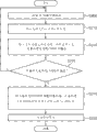
Fig. 9 is to use the flow chart of the method that the temperature controller of Fig. 6 comes the temperature in the machine room is controlled.
With reference to figure 9, in step S200, temperature controller is measured the temperature in the PC room.In step S210, the current opening degree of detection branch valve.
After the Current Temperatures in step S200 and S210, having measured the PC room and the current opening degree of bypass damper, in step S220, determine whether to change the opening degree of bypass damper based on current measurement temperature and current detection opening degree.For example; With at this moment before the computer room temperature measured compare, if current measurement temperature is in the preset temperature range (for example, ± 2 ℃); Then needn't change the opening degree of bypass damper; And if it has exceeded preset temperature range, then possibly change the opening degree of bypass damper, so that the temperature in the machine room is regulated.
The result who confirms as step S220; If must change the opening degree (S230) of bypass damper; Then in step S240; Be based on the current opening degree of Current Temperatures of measuring among the step S200 and the bypass damper that in step S210, detects, calculate the changing value of the opening degree of bypass damper, and create the signal of controlling bypass damper with corresponding being used to of changing value of calculating then.
Subsequently, in step S250, the control signal that temperature controller will be created in step S240 is sent to bypass damper.Then, bypass damper depends on that the control signal that transmits from temperature controller is adjusted at the air flow control panel that wherein provides, and makes the air that the PC cabinet is heated be discharged in the machine room or outside the machine room.
Figure 10 shows the view that provides according to the PC room of energy-saving air conditioning equipment of the present invention.
As shown in Figure 10, in the present invention, the PC main frame is installed in the PC cabinet, and in the PC cabinet, carries out overall maintenance, rather than is positioned on corresponding user's desk.Therefore, use the user in PC room under happy and comfortable more condition, to enjoy PC.In addition, the keeper of administration PC machine room can easily safeguard the PC main frame.
In addition because depend on the temperature in the machine room of measurement and the air that optionally uses the PC cabinet to be heated comes the air in the machine room is regulated, so can so that be used for to the air in PC room regulate energy consumption minimized.
That is, when the temperature in the machine room is relatively low, use by the air that heats from heat that the PC main frame generated to come air is circulated, air conditioning to be provided to machine room.When the temperature in the machine room when higher, will by from heat that the PC main frame generated and the air that heats directly be discharged into outside the machine room.Therefore, can be so that the air in PC room be regulated the energy minimization that is consumed.
Although disclose the preferred embodiments of the present invention for illustrative purposes, those skilled in the art will understand, and various modifications, interpolation and replacement are possible, and do not break away from disclosed scope of the present invention and spirit in the accompanying claims.
Claims (16)
Applications Claiming Priority (2)
| Application Number | Priority Date | Filing Date | Title |
|---|---|---|---|
| KR1020100052473A KR101351572B1 (en) | 2010-06-03 | 2010-06-03 | Energy-saving type air conditioning apparatus for green PC room, and method thereof |
| KR10-2010-0052473 | 2010-06-03 |
Publications (1)
| Publication Number | Publication Date |
|---|---|
| CN102331061A true CN102331061A (en) | 2012-01-25 |
Family
ID=45482942
Family Applications (1)
| Application Number | Title | Priority Date | Filing Date |
|---|---|---|---|
| CN2011101486390A Pending CN102331061A (en) | 2010-06-03 | 2011-06-03 | Energy-saving type air conditioning apparatus for PC room, and method thereof |
Country Status (2)
| Country | Link |
|---|---|
| KR (1) | KR101351572B1 (en) |
| CN (1) | CN102331061A (en) |
Families Citing this family (2)
| Publication number | Priority date | Publication date | Assignee | Title |
|---|---|---|---|---|
| CN103335373B (en) * | 2013-07-08 | 2016-06-22 | 华信咨询设计研究院有限公司 | Natural cooling ventilating system |
| KR102063340B1 (en) * | 2017-11-02 | 2020-01-08 | 주식회사 근옥 | Air cleaning device |
Citations (8)
| Publication number | Priority date | Publication date | Assignee | Title |
|---|---|---|---|---|
| WO2001086217A1 (en) * | 2000-05-09 | 2001-11-15 | Toc Technology, Llc | Computer rack heat extraction device |
| JP2003204183A (en) * | 2002-01-10 | 2003-07-18 | Hiroshi Kuramochi | Duct and rack |
| CN2872175Y (en) * | 2006-03-16 | 2007-02-21 | 史益华 | Energy-saving controller of base station of mobile telecommunication |
| CN2898690Y (en) * | 2006-03-22 | 2007-05-09 | 陈洪 | Electrically-controlled automatic radiator |
| CN101023718A (en) * | 2004-05-26 | 2007-08-22 | 惠普开发有限公司 | Energy-saving CRAC equipment operation |
| CN101236001A (en) * | 2007-01-30 | 2008-08-06 | 三菱电机株式会社 | Blowing device system for air conditioner, exhaust heat conveying device system, and air conditioning system having them |
| US20080185446A1 (en) * | 2007-02-07 | 2008-08-07 | Tozer Robert M | Cool design data center |
| CN101584261A (en) * | 2006-12-01 | 2009-11-18 | 雷希尔有限公司 | Equipment cabinet with a ventilation system |
Family Cites Families (2)
| Publication number | Priority date | Publication date | Assignee | Title |
|---|---|---|---|---|
| FI83134C (en) * | 1987-12-18 | 1991-05-27 | Ilmaterae Oy | Method and apparatus for regulating air currents and pressure in air conditioning |
| US6557357B2 (en) | 2000-02-18 | 2003-05-06 | Toc Technology, Llc | Computer rack heat extraction device |
-
2010
- 2010-06-03 KR KR1020100052473A patent/KR101351572B1/en not_active Expired - Fee Related
-
2011
- 2011-06-03 CN CN2011101486390A patent/CN102331061A/en active Pending
Patent Citations (8)
| Publication number | Priority date | Publication date | Assignee | Title |
|---|---|---|---|---|
| WO2001086217A1 (en) * | 2000-05-09 | 2001-11-15 | Toc Technology, Llc | Computer rack heat extraction device |
| JP2003204183A (en) * | 2002-01-10 | 2003-07-18 | Hiroshi Kuramochi | Duct and rack |
| CN101023718A (en) * | 2004-05-26 | 2007-08-22 | 惠普开发有限公司 | Energy-saving CRAC equipment operation |
| CN2872175Y (en) * | 2006-03-16 | 2007-02-21 | 史益华 | Energy-saving controller of base station of mobile telecommunication |
| CN2898690Y (en) * | 2006-03-22 | 2007-05-09 | 陈洪 | Electrically-controlled automatic radiator |
| CN101584261A (en) * | 2006-12-01 | 2009-11-18 | 雷希尔有限公司 | Equipment cabinet with a ventilation system |
| CN101236001A (en) * | 2007-01-30 | 2008-08-06 | 三菱电机株式会社 | Blowing device system for air conditioner, exhaust heat conveying device system, and air conditioning system having them |
| US20080185446A1 (en) * | 2007-02-07 | 2008-08-07 | Tozer Robert M | Cool design data center |
Also Published As
| Publication number | Publication date |
|---|---|
| KR101351572B1 (en) | 2014-01-16 |
| KR20110132883A (en) | 2011-12-09 |
Similar Documents
| Publication | Publication Date | Title |
|---|---|---|
| CN102472514B (en) | Ventilation system | |
| KR101911227B1 (en) | System for air conditioning in vessel and method thereof | |
| CN101291703A (en) | equipment for conveying compressed gas | |
| CN103673132B (en) | Energy-saving storehouse environmental index regulation and control all-in-one | |
| CN115388465A (en) | Wall-mounted fresh air conditioner indoor unit and air conditioner | |
| CN106678966A (en) | Low-noise modular air purification system | |
| CN219557167U (en) | Cleaning base station and cleaning robot system | |
| WO2013057844A1 (en) | Air conditioning system of communication/information processing apparatus chamber, etc. | |
| CN206338863U (en) | Low noise block air cleaning system | |
| JP6805714B2 (en) | Data center | |
| CN110332642A (en) | A kind of data center's fresh air temperature and humidity control system | |
| JP2005172309A (en) | Blower and air conditioning system for room | |
| CN107328032A (en) | A kind of Animal House two fans formula air conditioner intelligent control system | |
| JP2015169399A (en) | Ventilator | |
| CN102331061A (en) | Energy-saving type air conditioning apparatus for PC room, and method thereof | |
| JP2008281252A (en) | Ventilation system | |
| KR101950418B1 (en) | A wall type air conditioning system having multi-function | |
| CN103375857B (en) | Air-conditioning equipment based on high power density data center machine room | |
| CN205664492U (en) | Mix interior machine of wind formula air conditioning | |
| CN206890739U (en) | New blower fan | |
| CN111425934A (en) | Air treatment device | |
| CN108916998A (en) | A kind of ultra-thin wind pipe type exact constant temperature constant humidity energy-saving air-conditioning device | |
| CN105890123A (en) | GLV and fresh air independent temperature-humidity control system and mounting chamber thereof | |
| CN204830093U (en) | Lampblack absorber and air supply system adjusts temperature thereof | |
| CN207407641U (en) | The equal wind system of material |
Legal Events
| Date | Code | Title | Description |
|---|---|---|---|
| C06 | Publication | ||
| PB01 | Publication | ||
| C10 | Entry into substantive examination | ||
| SE01 | Entry into force of request for substantive examination | ||
| C12 | Rejection of a patent application after its publication | ||
| RJ01 | Rejection of invention patent application after publication |
Application publication date: 20120125 |