CN102243333B - Production method for all-fibre quarter-wave plate - Google Patents
Production method for all-fibre quarter-wave plate Download PDFInfo
- Publication number
- CN102243333B CN102243333B CN 201110194812 CN201110194812A CN102243333B CN 102243333 B CN102243333 B CN 102243333B CN 201110194812 CN201110194812 CN 201110194812 CN 201110194812 A CN201110194812 A CN 201110194812A CN 102243333 B CN102243333 B CN 102243333B
- Authority
- CN
- China
- Prior art keywords
- fiber
- wave plate
- optical fiber
- polarization
- optical
- Prior art date
- Legal status (The legal status is an assumption and is not a legal conclusion. Google has not performed a legal analysis and makes no representation as to the accuracy of the status listed.)
- Expired - Fee Related
Links
Images


Landscapes
- Mechanical Coupling Of Light Guides (AREA)
Abstract
Description
技术领域 technical field
本发明涉及全光纤电流互感器领域,尤其是一种全光纤电流互感器中四分之一波片制作方法。 The invention relates to the field of all-fiber-optic current transformers, in particular to a method for manufacturing a quarter-wave plate in an all-fiber-optic current transformer.
背景技术 Background technique
对于全光纤电流互感器的研制,目前采用的均是环形或反射式Sagnac干涉仪方案,该方案借鉴了目前较为成熟的光纤陀螺技术,这两种技术的光路结构、检测方法、关键技术等内容几乎完全一样,区别仅在于全光纤电流互感器比Sagnac型光纤陀螺多了一个关键光学器件--四分之一波片,其主要作用是将传输线路上的线偏振光转变为用于传感的圆偏振光,即为传输光信号与传感光信号的中转点,从而利用法拉第效应(外加磁场使得两束圆偏振光在传播一段距离后会产生一定的相位差,可通过测量该相位差来获得磁场及产生磁场的电流信息)进行电流检测。 For the development of all-fiber-optic current transformers, the annular or reflective Sagnac interferometer scheme is currently used. This scheme draws on the relatively mature fiber-optic gyroscope technology at present. The optical path structure, detection method, and key technology of these two technologies Almost exactly the same, the only difference is that the all-fiber current transformer has one more key optical device than the Sagnac-type fiber optic gyroscope—a quarter-wave plate, whose main function is to convert the linearly polarized light on the transmission line into a sensor for sensing. Circularly polarized light is the transition point between the transmitted optical signal and the sensory optical signal, thus using the Faraday effect (an external magnetic field causes two beams of circularly polarized light to produce a certain phase difference after a certain distance, which can be obtained by measuring the phase difference magnetic field and the current information that generates the magnetic field) for current detection.
四分之一波片在全光纤电流互感器中对光信号的偏振态起关键影响,但由于无法借鉴目前较为成熟的光纤陀螺技术,导致该器件成为全光纤电流互感器研制过程中最难的地方之一。 The quarter-wave plate plays a key role in the polarization state of the optical signal in the all-fiber current transformer, but because it cannot learn from the current relatively mature fiber optic gyroscope technology, this device has become the most difficult part in the development of the all-fiber current transformer. one of the places.
通过偏振控制器、晶体波片和全光纤波片都可以实现四分之一波片的功能,偏振控制器的结构设计非常复杂,不适合在工程实现中应用;晶体波片本身温度特性较好,但是存在空间光向光纤耦合的问题,稳定性较差;由光纤制成的全光纤四分之一波片,结构简单、紧凑,具有更大的带宽,能更好的与前后光纤进行连接,同时稳定性较好。 The function of a quarter-wave plate can be realized through a polarization controller, a crystal wave plate, and an all-fiber wave plate. The structural design of the polarization controller is very complicated and is not suitable for application in engineering implementation; the temperature characteristic of the crystal wave plate itself is better. , but there is the problem of spatial light coupling to the optical fiber, and the stability is poor; the all-fiber quarter-wave plate made of optical fiber has a simple and compact structure, has a larger bandwidth, and can better connect with the front and rear fibers , and better stability.
全光纤四分之一波片的制作原理及过程非常简单,由两段保偏光纤以45°对轴熔接,再截取输出端光纤的四分之一拍长长度制作而成,但在制作过程中不可避免地存在两大难点:首先是保偏光纤对轴角度的控制,即两段保偏光纤45°熔接时的对轴角度无法完全控制到45°,会存在一定的偏差(一般在±0.7°左右);其次,更困难的是,由于保偏光纤的拍长一般为几毫米(拍长为保偏光纤的一项基本参数,其指标一般在2mm~10mm范围内,国际上的最高指标也没超过30mm,只能达到20mm左右),因此很难在毫米级的长度上精确的截取四分之一拍长长度。全光纤四分之一波片的两大制作难点使制作好的波片存在一定的误差,从而导致全光纤电流互感器也存在误差,使其测量准确度达不到电力系统的计量要求。 The production principle and process of the all-fiber quarter-wave plate are very simple. It is made by splicing two sections of polarization-maintaining optical fiber at 45° to the axis, and then intercepting the quarter-beat length of the optical fiber at the output end. However, in the production process Inevitably, there are two major difficulties: the first is the control of the axis angle of the polarization maintaining fiber, that is, the axis angle cannot be completely controlled to 45° when two sections of polarization maintaining fiber are spliced at 45°, and there will be a certain deviation (generally within ± 0.7°); Secondly, it is more difficult because the beat length of the polarization maintaining fiber is generally a few millimeters (the beat length is a basic parameter of the polarization maintaining fiber, and its index is generally in the range of 2mm to 10mm, the highest in the world The index does not exceed 30mm, and can only reach about 20mm), so it is difficult to accurately intercept the length of a quarter of a shot at the millimeter level. The two major difficulties in the manufacture of the all-fiber quarter-wave plate lead to certain errors in the fabricated wave plate, which leads to errors in the all-fiber current transformer, making its measurement accuracy fail to meet the measurement requirements of the power system.
全光纤四分之一波片制作过程中的两大难点是目前国际上光纤传感领域的共有难题,尤其是精确截取四分之一拍长长度的难点,导致该器件成为全光纤电流互感器研制过程中最大的瓶颈。 The two major difficulties in the production process of the all-fiber quarter-wave plate are common problems in the field of optical fiber sensing in the world at present, especially the difficulty of accurately intercepting the quarter-wave length, which makes the device become an all-fiber current transformer. The biggest bottleneck in the development process.
发明内容 Contents of the invention
本发明针对上述存在的问题,提供一种全光纤四分之一波片及制作方法,能有效的解决全光纤四分之一波片制作过程中的两大难点。 Aiming at the above-mentioned problems, the present invention provides an all-fiber quarter-wave plate and a manufacturing method thereof, which can effectively solve two major difficulties in the production process of the all-fiber quarter-wave plate.
本发明采用的技术方案如下: The technical scheme that the present invention adopts is as follows:
一种全光纤四分之一波片制作方法,包括以下步骤: A method for manufacturing an all-fiber quarter-wave plate, comprising the following steps:
步骤一:搭建偏振光光源装置,生成线偏振光,作为制作波片时用于监测的信号光; Step 1: Build a polarized light source device to generate linearly polarized light as the signal light for monitoring when making wave plates;
步骤二:将偏振光光源装置与全光纤波片输入端光纤一端熔接; Step 2: Fusion the polarized light source device with one end of the optical fiber at the input end of the all-fiber wave plate;
步骤三:全光纤波片输入端光纤另一端与波片光纤一端进行45°熔接; Step 3: The other end of the fiber at the input end of the all-fiber wave plate is welded at 45° to one end of the wave plate fiber;
步骤四:截取波片光纤四分之一拍长长度; Step 4: Intercept the length of the wave plate fiber to a quarter of the beat length;
步骤五:测试截取后波片光纤输出的光信号; Step 5: Test the optical signal output by the wave plate fiber after interception;
步骤六:熔接全光纤波片输出端光纤与波片光纤另一端。 Step 6: Splice the fiber at the output end of the all-fiber wave plate and the other end of the wave plate fiber.
所述步骤一中偏振光光源装置包括SLED光源、光纤起偏器、SLED光源光纤、光纤起偏器光纤,将SLED光源光纤输出端与光纤起偏器光纤输入端在保偏光纤熔接机中进行熔接,从而SLED光源输出的光信号经过光纤起偏器起偏后,生成具有较高偏振度的线偏振光,并由光纤起偏器输出端光纤引出,作为制作波片时用于监测的信号光,然后松开保偏光纤熔接机夹具,取出熔接好的光纤。
In the
所述步骤二具体步骤包括: The specific steps of the second step include:
b1)光纤起偏器光纤输出端与全光纤波片输入端光纤一端放入保偏光纤熔接机的两个光纤夹具中,采用半自动熔接方式在熔接机里对准; b1) Put the optical fiber output end of the optical fiber polarizer and the optical fiber end of the all-fiber wave plate input end into the two optical fiber fixtures of the polarization-maintaining optical fiber fusion splicer, and align them in the fusion splicer by semi-automatic fusion splicing;
b2)全光纤波片输入端光纤另一端接入偏振分析仪,偏振分析仪对其传输光信号的偏振消光比和偏振度进行实时检测; b2) The other end of the optical fiber at the input end of the all-fiber wave plate is connected to a polarization analyzer, and the polarization analyzer performs real-time detection of the polarization extinction ratio and polarization degree of the transmitted optical signal;
b3)通过调节保偏光纤熔接机的马达,手动旋转全光纤波片输入端光纤,当全光纤波片输入端光纤传输光信号的偏振消光比达到20dB~40dB且偏振度接近100%时,进行放电熔接,精确实现光纤起偏器光纤输出端与全光纤波片输入端光纤的对轴熔接; b3) By adjusting the motor of the polarization-maintaining fiber fusion splicer, manually rotate the fiber at the input end of the all-fiber wave plate. When the polarization extinction ratio of the optical signal transmitted by the optical fiber at the input end of the all-fiber wave plate reaches 20dB-40dB and the degree of polarization is close to 100%, perform Discharge fusion splicing, accurately realize the on-axis fusion splicing of the optical fiber output end of the optical fiber polarizer and the optical fiber input end of the all-fiber wave plate;
b4)松开保偏光纤熔接机夹具,取出熔接好的光纤。 b4) Loosen the clamp of the polarization-maintaining optical fiber fusion splicer, and take out the fused optical fiber.
所述步骤三具体步骤包括: Described step three specific steps include:
c1)将全光纤波片输入端光纤另一端与波片光纤的一端放入保偏光纤熔接机的两个光纤夹具中,采用半自动熔接方式在熔接机里对准,而波片光纤另一端接入偏振分析仪,对波片光纤中传输的光信号的偏振消光比和偏振度进行实时检测; c1) Put the other end of the fiber at the input end of the all-fiber wave plate and one end of the wave plate fiber into the two fiber fixtures of the polarization maintaining fiber fusion splicer, and align them in the fusion splicer by semi-automatic fusion splicing, while the other end of the wave plate fiber is connected Incoming polarization analyzer, which detects the polarization extinction ratio and polarization degree of the optical signal transmitted in the wave plate fiber in real time;
c2)通过调节保偏光纤熔接机,手动旋转波片光纤,当波片光纤传输光信号的偏振消光比接近0dB且偏振度接近100%时,进行放电熔接,精确实现保偏光纤45°熔接点的熔接。 c2) By adjusting the polarization maintaining fiber fusion splicer and manually rotating the wave plate fiber, when the polarization extinction ratio of the optical signal transmitted by the wave plate fiber is close to 0dB and the degree of polarization is close to 100%, discharge fusion is performed to accurately realize the 45° fusion point of the polarization maintaining fiber of welding.
c3)松开保偏光纤熔接机夹具; c3) Loosen the clamp of the polarization maintaining optical fiber fusion splicer;
所述步骤四是将45°熔接点、全光纤波片输入端光纤与波片光纤组成的光纤段从保偏光纤熔接机中取出,通过游标卡尺和光纤切割刀截取波片光纤四分之一拍长长度,截取后光纤段包含有全光纤波片输入端光纤、45°熔接点和仅剩四分之一拍长长度的波片光纤。 The fourth step is to take out the fiber section composed of the 45° fusion splicing point, the fiber at the input end of the all-fiber wave plate and the wave plate fiber from the polarization-maintaining fiber fusion splicer, and cut off a quarter of the wave plate fiber by using a vernier caliper and a fiber cutter Long length, after cutting, the fiber section includes the fiber at the input end of the all-fiber wave plate, the 45° fusion splicing point, and the wave plate fiber with only a quarter of the beat length remaining.
所述步骤五是将截取后的光纤段接入偏振分析仪,对波片光纤中传输光信号的偏振消光比和偏振度进行检测,当偏振消光低于2.0dB且偏振度高于95%时,可认为制作出了理想的全光纤四分之一波片,否则重复步骤二到步骤五。
The fifth step is to connect the intercepted optical fiber section to a polarization analyzer to detect the polarization extinction ratio and the degree of polarization of the transmitted optical signal in the wave plate optical fiber. When the polarization extinction is lower than 2.0dB and the degree of polarization is higher than 95% , it can be considered that an ideal all-fiber quarter-wave plate has been produced, otherwise, repeat
所述步骤六是波片光纤另一端与全光纤波片输出端光纤在保偏光纤熔接机中进行熔接。 The sixth step is that the other end of the wave plate fiber is fused with the output fiber of the all-fiber wave plate in a polarization-maintaining fiber fusion splicer.
所述光纤起偏器光纤、全光纤波片输入端光纤、波片光纤为保偏光纤,所述全光纤波片输出端光纤为低双折射光纤或单模光纤。 The optical fiber polarizer fiber, the optical fiber at the input end of the all-fiber wave plate, and the optical fiber at the wave plate are polarization-maintaining optical fibers, and the optical fiber at the output end of the all-fiber wave plate is a low-birefringence optical fiber or a single-mode optical fiber.
所述波片光纤为椭圆纤芯型或一字型的保偏光纤。 The wave plate optical fiber is an elliptical core type or an in-line polarization maintaining optical fiber.
综上所述,由于采用了上述技术方案,本发明的有益效果是: In summary, owing to adopting above-mentioned technical scheme, the beneficial effect of the present invention is:
通过一系列的优化措施,解决了目前国内外在制作全光纤四分之一波片时的两大难点—保偏光纤熔接时的对轴误差控制和波片光纤毫米级的四分之一拍长长度的精确截取,提高了全光纤四分之一波片当前的制作水平,为成功研制出满足应用要求的全光纤电流互感器奠定了基础: Through a series of optimization measures, the two major difficulties in the production of all-fiber quarter-wave plates at home and abroad have been solved—the axis error control during polarization-maintaining fiber fusion splicing and the millimeter-level quarter-beat of wave plate fibers. The precise cutting of the long length has improved the current production level of the all-fiber quarter-wave plate and laid the foundation for the successful development of an all-fiber current transformer that meets the application requirements:
1)放弃全自动熔接方式,而采用半自动熔接方式,即先采用熔接机的半自动对准方式将两端的保偏光纤初步对轴,使对轴准确度达到±0.7°左右,再调节熔接机的马达,手动旋转光纤轴向,同时加上偏振分析仪进行实时检测,达到所需测试值时再进行放电熔接,该熔接方式放弃了通过CCD分辨光纤图像来判断快慢轴的传统熔接方式,而通过偏振分析仪的测试值来判断快慢轴,可使对轴准确度大幅提高到±0.2°(依靠熔接机自身的发展,该指标还有较大的提升空间),即熔接机马达本身的旋转准确度,而忽略CCD较低的分辨率对光纤对轴的影响,从而使该方法制作的全光纤四分之一波片的对轴误差大幅低于目前通常的制作水平。此外,本发明的熔接方式通用于任意类型的保偏光纤,改进了全自动熔接方式的熔接程序有限,而只能熔接几种通常类型的保偏光纤,无法对特殊的保偏光纤进行熔接的缺陷(制作全光纤波片时有可能涉及到一些特殊的保偏光纤),同时还解决了更换保偏光纤类型后必须更换熔接程序的问题,提高了熔接效率。 1) Abandon the automatic fusion splicing method and adopt the semi-automatic fusion splicing method, that is, first use the semi-automatic alignment method of the fusion splicer to initially align the polarization-maintaining optical fibers at both ends, so that the alignment accuracy can reach about ±0.7°, and then adjust the splicing machine. The motor rotates the fiber axis manually, and at the same time, a polarization analyzer is used for real-time detection. When the required test value is reached, the discharge fusion is performed. This fusion method abandons the traditional fusion method of judging the fast and slow axes by distinguishing the fiber image through the CCD. The test value of the polarization analyzer is used to judge the fast and slow axis, which can greatly improve the accuracy of the axis alignment to ±0.2° (depending on the development of the fusion splicer itself, this indicator still has a large room for improvement), that is, the rotation of the fusion splicer motor itself is accurate. Degree, while ignoring the impact of the lower resolution of the CCD on the axis of the fiber, so that the axis error of the all-fiber quarter-wave plate produced by this method is significantly lower than the current usual production level. In addition, the fusion splicing method of the present invention is generally applicable to any type of polarization-maintaining optical fiber, and the fusion splicing procedure of the improved automatic fusion splicing method is limited, but only several common types of polarization-maintaining optical fibers can be fused, and special polarization-maintaining optical fibers cannot be fused. Defects (some special polarization-maintaining fibers may be involved in the production of all-fiber waveplates), and it also solves the problem of having to change the fusion splicing procedure after changing the type of polarization-maintaining fiber, and improves the splicing efficiency.
2)对熔接效果及波片性能的验证,不仅采用了检测偏振消光比的传统方式,还同时对偏振度进行检测,通过对比验证来提高熔接质量,此外,全光纤四分之一波片输出光的消光比最低的物理特征即可表征两端光纤主轴45°对准且输出光为圆偏振光,也可表征输出光为非偏振光即器件完全制作失败,即还可通过偏振度的对比验证来解决仅凭偏振消光比一项参数无法真正证明波片制作效果的弊端。 2) For the verification of the fusion effect and the performance of the wave plate, not only the traditional method of detecting the polarization extinction ratio is adopted, but also the degree of polarization is detected at the same time, and the quality of the fusion splicing is improved through comparison and verification. The physical characteristic of the lowest extinction ratio of light can be characterized by the 45° alignment of the main axes of the fibers at both ends and the output light is circularly polarized light, or that the output light is non-polarized light, that is, the device has completely failed, that is, the comparison of the degree of polarization can also be passed Verification is used to solve the disadvantage that the polarization extinction ratio alone cannot really prove the effect of wave plate production.
3)在熔接保偏光纤熔接点时,放弃了目前通常采用的熔接机自动熔接好后再用偏振分析设备检测的被动检测方式(该方式的弊端在于检测效果不理想时需要切断光纤熔接点并重新熔接),而在对准两端光纤并调节熔接机马达以旋转光纤轴向时就用偏振分析设备进行实时监测,测试值达到要求后才进行放电熔接,这种主动式的检测方式的优势在于光纤熔接时的调试、优化及重新制作都更具灵活性,测试值不理想时仅需继续旋转两端光纤轴向,而无须切断光纤熔接点并重新熔接,从而提高了熔接效率和波片的制作效率。 3) When splicing polarization-maintaining optical fiber splicing points, the passive detection method that is usually used by the fusion splicer after automatic splicing is abandoned and then detected by polarization analysis equipment (the disadvantage of this method is that it is necessary to cut off the optical fiber splicing points and When aligning the fibers at both ends and adjusting the motor of the fusion splicer to rotate the fiber axis, the polarization analysis equipment is used for real-time monitoring, and the discharge fusion is performed after the test value meets the requirements. The advantages of this active detection method It is more flexible to debug, optimize and remake during fiber splicing. When the test value is not ideal, it is only necessary to continue to rotate the axes of the fibers at both ends without cutting off the fiber splicing point and re-splicing, thereby improving the splicing efficiency and wave plate. production efficiency.
4)全光纤四分之一波片的波片光纤采用椭圆纤芯型保偏光纤或一字型保偏光纤,该类光纤具有特殊的结构,可以降低波片对外界环境因素(温度、振动、应力等)影响的敏感性。 4) The wave plate fiber of the all-fiber quarter wave plate adopts elliptical core type polarization maintaining fiber or inline polarization maintaining fiber. This type of fiber has a special structure, which can reduce the impact of the wave plate on external environmental factors (temperature, vibration , stress, etc.) influence sensitivity.
5)对于波片光纤四分之一拍长长度的截取,采用步骤四的截取方法,解决了无法确定波片光纤起始位置(即截取长度的起始位置)导致的无法确定切割点精确位置(即截取长度的位置)的问题,利用50个分格的游标卡尺将截取长度误差控制在0.02毫米左右,远高于目前的制作水平。此外,目前国内外均未见报道过能有效降低长度误差的截取方法,在制作全光纤波片时,对于截取毫米级的四分之一拍长长度,大多凭操作者的经验,通常需要尝试数次后才能有一次效果较好,效率很低,而本发明的截取方法及装置简单可靠,具有非常好的可操作性和重复性,一般均可一次完成,在大幅降低了截取长度误差的同时,还提高了制作效率。
5) For the interception of the quarter-beat length of the wave plate fiber, the interception method of
附图说明 Description of drawings
本发明将通过例子并参照附图的方式说明,其中: The invention will be illustrated by way of example with reference to the accompanying drawings, in which:
图1是光纤陀螺的基本结构; Figure 1 is the basic structure of the fiber optic gyroscope;
图2是环形方案全光纤电流互感器的基本结构; Fig. 2 is the basic structure of the all-fiber optic current transformer of the ring scheme;
图3是反射式方案全光纤电流互感器的基本结构; Fig. 3 is the basic structure of the all-fiber optic current transformer of the reflective scheme;
图4是光纤切割示意图; Fig. 4 is a schematic diagram of optical fiber cutting;
图5是几种常规类型保偏光纤的基本结构; Fig. 5 is the basic structure of several conventional types of polarization-maintaining optical fibers;
图6是本发明的全光纤四分之一波片制作示意图; Fig. 6 is a schematic diagram of making an all-fiber quarter-wave plate of the present invention;
图7是本发明的全光纤四分之一波片的结构。 Fig. 7 is the structure of the all-fiber quarter-wave plate of the present invention.
图中:1-SLED光源;2-光纤起偏器;3-光探测器;4-信号处理单元;5-光学相位调制器;6-传感光纤圈;7-四分之一波片;8-端面反射镜;9-偏振分析仪;10-全光纤波片输入端光纤;11-波片光纤;12-全光纤波片输出端光纤;13-保偏光纤对轴熔接点;14-保偏光纤45°熔接点;15-光纤熔接点。 In the figure: 1-SLED light source; 2-optical fiber polarizer; 3-photodetector; 4-signal processing unit; 5-optical phase modulator; 6-sensing fiber coil; 7-quarter wave plate; 8-end mirror; 9-polarization analyzer; 10-optical fiber at the input end of the all-fiber wave plate; 11-fiber at the wave plate; 12-fiber at the output end of the all-fiber wave plate; Polarization maintaining fiber 45° splicing point; 15-fiber splicing point. the
具体实施方式 Detailed ways
本说明书中公开的所有特征,或公开的所有方法或过程中的步骤,除了互相排斥的特征和/或步骤以外,均可以以任何方式组合。 All features disclosed in this specification, or steps in all methods or processes disclosed, may be combined in any manner, except for mutually exclusive features and/or steps.
本说明书(包括任何附加权利要求、摘要和附图)中公开的任一特征,除非特别叙述,均可被其他等效或具有类似目的的替代特征加以替换。即,除非特别叙述,每个特征只是一系列等效或类似特征中的一个例子而已。 Any feature disclosed in this specification (including any appended claims, abstract and drawings), unless expressly stated otherwise, may be replaced by alternative features which are equivalent or serve a similar purpose. That is, unless expressly stated otherwise, each feature is one example only of a series of equivalent or similar features.
如图1 所示,光纤陀螺是测量物体角速度的一种技术,其原理是 SLED光源1产生宽谱光,经光纤起偏器2起偏后输入传感光纤圈6,来感应被测物体的角速度信息。包含角速度信息的光信号通过环路回到光探测器3,转化为电信号,送入信号处理单元4中进行运算处理,从而得到被测物体的角速度信息,同时信号处理单元4产生一定参数的调制电压,通过光学相位调制器5对光信号进行调制,以提高系统的检测性能。
As shown in Figure 1, the fiber optic gyroscope is a technology for measuring the angular velocity of an object. Its principle is that the SLED
全光纤电流互感器是测量带电导体中的电流大小一种技术,如图2和图3所示。图2为环形方案的全光纤电流互感器,它与图1中的光纤陀螺相比,区别仅在于多了一种关键光学器件--四分之一波片7,除此之外,系统中信号产生、传输与处理的过程完全一样。四分之一波片7的主要作用是将传输线路上的线偏振光转变为用于传感的圆偏振光,即为传输光信号与传感光信号的中转点,从而利用法拉第效应(外加磁场使得两束圆偏振光在传播一段距离后会产生一定的相位差,可通过测量该相位差来获得磁场及产生磁场的电流信息)进行电流检测。图3为反射式的全光纤电流互感器,与图1和图2相比,区别之一在于用一个端面反射镜8反射回光信号,以替代图1和图2中通过环路传回光信号的方法,区别之二在于光纤起偏器2与后端光纤45°连接,其他方面则等同于环形方案的全光纤电流互感器。
The all-fiber-optic current transformer is a technology for measuring the magnitude of the current in a live conductor, as shown in Figure 2 and Figure 3. Figure 2 is an all-fiber-optic current transformer of the ring scheme. Compared with the fiber-optic gyroscope in Figure 1, the only difference is that there is one more key optical device—a quarter-wave plate 7. In addition, in the system The process of signal generation, transmission and processing is exactly the same. The main function of the quarter-wave plate 7 is to convert the linearly polarized light on the transmission line into circularly polarized light for sensing, which is the transition point between the transmission optical signal and the sensing optical signal, thereby utilizing the Faraday effect (applied magnetic field makes Two beams of circularly polarized light will produce a certain phase difference after traveling a certain distance. The phase difference can be measured to obtain the magnetic field and the current information that generates the magnetic field) for current detection. Fig. 3 is a reflective all-fiber current transformer. Compared with Fig. 1 and Fig. 2, one of the differences is that an end mirror 8 is used to reflect the return light signal instead of returning light through the loop in Fig. 1 and Fig. 2 The signal method, the second difference is that the
综上所述,除了四分之一波片外,全光纤电流互感器的光路结构、检测方法、关键技术等内容和光纤陀螺几乎完全一样,但四分之一波片在全光纤电流互感器中对光信号的偏振态起关键影响,由于无法借鉴目前较为成熟的光纤陀螺技术,从而导致该器件成为全光纤电流互感器研制过程中最难的地方之一,成为最大的瓶颈。 In summary, except for the quarter-wave plate, the optical path structure, detection method, key technology and other contents of the all-fiber optic current transformer are almost exactly the same as those of the fiber optic gyroscope, but the quarter-wave plate is in the all-fiber current transformer It has a key influence on the polarization state of the optical signal. Since the current relatively mature fiber optic gyroscope technology cannot be used for reference, this device has become one of the most difficult parts in the development of all-fiber optic current transformers, and has become the biggest bottleneck.
全光纤波片为使传输光两个等量模式之间产生π/2相位延迟的器件,即将输入的线偏振光转换为圆偏振光,它一般由两段保偏光纤45°对接,并截取输出端保偏光纤四分之一拍长长度制成。 The all-fiber wave plate is a device that produces a π/2 phase delay between two equal-quantity modes of the transmitted light, that is, converts the input linearly polarized light into circularly polarized light. It is generally connected by two sections of polarization-maintaining fiber at 45°, and intercepts The polarization maintaining fiber at the output end is fabricated with a quarter-beat length.
两段保偏光纤45°对接的作用是将前端保偏光纤输入的线偏振光分成等量大小的两个模式(或者说将输入的偏振光等分为两份并注入输出端保偏光纤的两个正交轴向中),但熔接时的对轴角度无法完全控制到45°,会存在一定的偏差(一般在±0.7°左右),使被分开的两个模式(两个正交模式)不等量,导致经全光纤波片转化后的圆偏振光的圆度不好,从而严重影响波片的性能。 The role of the 45° butt joint of two sections of polarization-maintaining fiber is to divide the linearly polarized light input by the front-end polarization-maintaining fiber into two modes of equal size (or divide the input polarized light into two equal parts and inject them into the output end of the polarization-maintaining fiber. Two orthogonal axes), but the axis angle during welding cannot be fully controlled to 45°, there will be a certain deviation (generally around ±0.7°), so that the two modes that are separated (two orthogonal modes ) are not equal, resulting in poor roundness of the circularly polarized light converted by the all-fiber wave plate, which seriously affects the performance of the wave plate.
截取输出端保偏光纤四分之一拍长长度的作用是使两个模式产生π/2相位延迟,其原理为,由于保偏光纤中存在双折射,偏振光在保偏光纤中传输时,其两个模式之间的相位延迟为 The effect of intercepting a quarter of the beat length of the polarization-maintaining fiber at the output end is to cause the two modes to produce a π/2 phase delay. The principle is that due to the birefringence in the polarization-maintaining fiber, when the polarized light is transmitted in the polarization-maintaining fiber, The phase delay between its two modes is
式中 

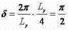
即当截取保偏光纤四分之一拍长长度时,两个模式之间的相位延迟精确的等于π/2,此时该光纤波片可将输入光信号转化为理想的圆偏振光(理论上也可截取四分之三拍长长度,即相位延迟为3π/2,也可转换为圆偏振光,但截取光纤的长度一般情况下越短越好,因为波片光纤越长就越容易受外界环境干扰,所以一般不推荐此截取长度),而当出现截取长度误差时,两个模式之间的相位延迟会偏离π/2,导致波片指标下降和性能退化,无法将输入光信号转化为理想的圆偏振光,而被转化成椭圆偏振光。 That is, when a quarter of the beat length of the polarization-maintaining fiber is intercepted, the phase delay between the two modes is exactly equal to π/2. At this time, the fiber wave plate can convert the input optical signal into an ideal circularly polarized light (theoretical It is also possible to intercept three-quarters of the beat length, that is, the phase delay is 3π/2, and it can also be converted into circularly polarized light, but the shorter the length of the intercepted fiber, the better, because the longer the wave plate fiber, the easier it is Due to interference from the external environment, this interception length is generally not recommended), and when there is an error in the interception length, the phase delay between the two modes will deviate from π/2, resulting in a decrease in the wave plate index and performance degradation, and the input optical signal cannot be Converted to ideal circularly polarized light, and converted to elliptically polarized light.
光纤非常细(一般外径为250mm)且具有较强的韧性,切断光纤或截取一定的光纤长度时只能使用专用的光纤切割刀(未图示)(保偏光纤熔接机的附属工具),才能保证截断后的光纤具有平滑且清洁的端面,从而可以和后端的光纤进行熔接(在光纤熔接机里,只有两根光纤均具有平滑且清洁的端面,才满足进行放电熔接的基本条件),而使用剪刀、普通刀片、钳子等常规工具截断光纤时,光纤端面会出现大量的毛刺,无法和后端的光纤进行熔接。光纤切割刀包含一个专用刀片、一个特定的夹具(和保偏光纤熔接机通用)和其他一些附属部件,夹具夹住光纤并让该光纤的一部分悬空放置于刀片正上方,通过一些特殊部件的瞬间施力作用,刀片在极大的受力条件下和这些特殊部件一起将光纤瞬间切断,切断点为光纤上处于刀片正上方的b点。由于光纤切割刀特殊的结构及狭窄的内部空间,很难使用精密工具量长度和精密的移动一定的长度,此外,切点附近的一小段光纤是悬空放置的,量长度或移动光纤时会让光纤轻微晃动,产生测量长度误差或移动长度误差。 The optical fiber is very thin (generally the outer diameter is 250mm) and has strong toughness. When cutting the optical fiber or cutting a certain length of the optical fiber, only a special optical fiber cutter (not shown) (an accessory tool for the polarization-maintaining optical fiber fusion splicer) can be used. In order to ensure that the truncated optical fiber has a smooth and clean end face, it can be fused with the back-end optical fiber (in the optical fiber fusion splicer, only two optical fibers with smooth and clean end faces can meet the basic conditions for discharge fusion), However, when using conventional tools such as scissors, ordinary blades, and pliers to cut the optical fiber, a large number of burrs will appear on the end face of the optical fiber, which cannot be fused with the optical fiber at the rear end. The fiber cleaver consists of a special blade, a specific fixture (common to polarization-maintaining fiber fusion splicers) and some other accessories. The fixture clamps the fiber and allows a part of the fiber to be suspended directly above the blade. Under the action of force, the blade cuts the optical fiber instantaneously together with these special components under the condition of great force, and the cutting point is point b on the optical fiber directly above the blade. Due to the special structure and narrow internal space of the fiber cleaver, it is difficult to use precision tools to measure the length and move a certain length precisely. In addition, a small section of optical fiber near the cutting point is placed in the air, and it will be difficult to measure the length or move the optical fiber. Optical fiber shakes slightly, resulting in measurement length error or movement length error.
以图4所示的切割基本原理来说明截取四分之一拍长光纤长度的具体方式及其产生误差的机理。光纤A和保偏光纤B通过熔接点a熔接在一起,要保证切断后保偏光纤B的长度恰好等于其四分之一拍长长度,就必须精确的使光纤上该长度所对应的位置处于刀片正上方,即必须保证a点和b点之间的长度精确的等于保偏光纤B的四分之一拍长长度。 The basic principle of cutting shown in Figure 4 is used to illustrate the specific method of cutting the length of a quarter-beat-length fiber and the mechanism of the error. Optical fiber A and polarization-maintaining optical fiber B are fused together through fusion splicing point a. To ensure that the length of polarization-maintaining optical fiber B after cutting is exactly equal to its quarter-beat length, the position corresponding to the length on the optical fiber must be precisely at Right above the blade, that is, it must be ensured that the length between point a and point b is exactly equal to a quarter of the beat length of polarization-maintaining fiber B.
困难的是,光纤熔接点处于光纤内部,在光纤外部很难辨识出熔接点并确定其位置,以图4为例,无法确定光纤熔接点a的位置(即光纤B的起始位置),起点未知,从而不能使用精密工具对光纤B进行长度测量并将该长度对应的位置放于切割刀刀片的正上方以进行切割,即对光纤B无法截取精确的长度。 The difficulty is that the fiber fusion point is inside the fiber, and it is difficult to identify the fusion point and determine its position outside the fiber. Taking Figure 4 as an example, it is impossible to determine the position of the fiber fusion point a (that is, the starting position of fiber B), the starting point It is unknown, so it is impossible to use precision tools to measure the length of the optical fiber B and place the position corresponding to the length directly above the cleaver blade for cutting, that is, it is impossible to cut the precise length of the optical fiber B.
由上所述,光纤及其熔接点的特殊结构,以及光纤切割刀特殊的切割原理让其很难决定切点在光纤上的精确位置,同时保偏光纤的拍长一般为几毫米,因此几乎不可能在毫米量级的情况下使四分之一拍长长度所对应的位置精确的处于刀片正上方,其偏差
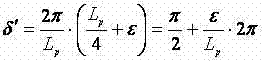
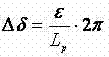
目前国内外均未见报道过能有效降低截取长度误差的方法,在制作全光纤波片时,对于截取毫米级的四分之一拍长长度,大多凭操作者的经验进行尝试性的操作,偏差较大,在较为理想的情况下,假设偏差
即波片的指标偏离π/2(90°)了3.6°,偏离了理想值1/25,使波片性能退化并造成了较大的测量误差。 That is, the index of the wave plate deviates from π/2 (90°) by 3.6°, which deviates from the ideal value by 1/25, which degrades the performance of the wave plate and causes a large measurement error.
保偏光纤指能保持住传输光偏振态的光纤,一般包含熊猫型、领结型、椭圆包层型等,几种常规类型保偏光纤的基本结构如图5所示的,每类保偏光纤都有两个相互正交的轴向--快轴和慢轴(x轴和y轴),熔接时一般需要将两端光纤的轴向对准(一端光纤的快慢轴对准另一端光纤的快慢轴),即对轴熔接,此时熔接点后的传输光充分保持住了输入偏振光的偏振特性,其偏振消光比达到最大值,一般为20dB~40dB,而当两段保偏光纤的轴向旋转45°对准时,传输光的偏振消光比达到最小值,一般接近零,但偏振度不变。 Polarization-maintaining fiber refers to the fiber that can maintain the polarization state of the transmitted light, generally including panda type, bow-tie type, elliptical cladding type, etc. The basic structure of several conventional types of polarization-maintaining fiber is shown in Figure 5. Each type of polarization-maintaining fiber There are two mutually orthogonal axes - the fast axis and the slow axis (x-axis and y-axis). Generally, the axes of the fibers at both ends need to be aligned during fusion splicing (the fast and slow axes of the fibers at one end are aligned with the fibers at the other end) Fast and slow axis), that is, the opposite axis fusion, at this time, the transmitted light after the fusion point fully maintains the polarization characteristics of the input polarized light, and its polarization extinction ratio reaches the maximum value, generally 20dB ~ 40dB, and when the two sections of polarization maintaining fiber When the axis is rotated by 45° to align, the polarization extinction ratio of the transmitted light reaches the minimum value, generally close to zero, but the degree of polarization remains unchanged.
具体的,偏振消光比指沿偏振主态方向分解的两个正交偏振分量之间的大小关系,一般以对数值表示,对于线偏振光,消光比理论上为无穷大(值越大表征线偏振特性越好),圆偏振光的消光比为0,非偏振光(即完全自然光)的消光比也为0,其他偏振光的消光比介于0和无穷大之间。受制于器件的非理想性,实际上偏振消光比一般不会超过40dB,也无法完全等于0,而只能接近0。偏振度是传输光偏振态的另一个关键参数,定义为偏振光成分占总光强(或光功率)的比例,其取值范围为0~100%,最大值是100%,最小值是0,偏振度越接近100%,表明该光信号的偏振性越好,杂散的非偏振成分越小。 Specifically, the polarization extinction ratio refers to the magnitude relationship between the two orthogonal polarization components decomposed along the polarization main state direction, and is generally expressed in logarithmic values. For linearly polarized light, the extinction ratio is theoretically infinite (the larger the value, the more linear polarization The better the characteristics), the extinction ratio of circularly polarized light is 0, the extinction ratio of unpolarized light (that is, completely natural light) is also 0, and the extinction ratio of other polarized light is between 0 and infinity. Due to the non-ideality of the device, in fact, the polarization extinction ratio generally does not exceed 40dB, and it cannot be completely equal to 0, but can only be close to 0. The degree of polarization is another key parameter of the polarization state of the transmitted light. It is defined as the ratio of the polarized light component to the total light intensity (or light power). Its value ranges from 0 to 100%, the maximum value is 100%, and the minimum value is 0. , the closer the degree of polarization is to 100%, the better the polarization of the optical signal and the smaller the stray non-polarized components.
具体的,所述保偏光纤熔接机(未图示)对各类保偏光纤的熔接是先用自带的CCD相机从光纤图像中分辨出快慢轴,然后旋转马达使两端光纤快慢轴的轴向对准,再放电熔接,该方式的对轴准确度由马达旋转准确度、CCD分辨率和保偏光纤本身决定。对于目前市面上的常规保偏光纤,保偏光纤本身带来的熔接对轴误差较小,因此保偏光纤熔接机的对轴准确度主要由马达旋转准确度和CCD分辨率决定,在国际上目前的相关产品中,马达旋转准确度一般在0.2°左右,CCD分辨率一般为0.5°左右,因此,全自动熔接时的对轴准确度一般低于±0.7°,这也是目前制作全光纤四分之一波片时通常的对轴水平。此外,对于不同类型的保偏光纤,熔接机进行熔接时所采用的熔接参数(通过熔接程序设置并进行控制)并不相同,某一组熔接参数(即某一个熔接程序)仅能熔接对应的某一类保偏光纤,换了光纤类型后,熔接机所使用的程序必须更换为该类光纤所对应的熔接程序。此外,市面上的保偏光纤熔接机一般只有几种通常类型保偏光纤的熔接程序,对于特殊的保偏光纤,必须另外订制其熔接程序,这不仅增加成本,而且存在程序无法编制成功的可能性。 Specifically, the polarization-maintaining fiber fusion splicer (not shown) first uses the built-in CCD camera to distinguish the fast and slow axes from the fiber image, and then rotates the motor to make the fast and slow axes of the fibers at both ends Axial alignment, followed by discharge welding, the axis alignment accuracy of this method is determined by the motor rotation accuracy, CCD resolution and polarization maintaining fiber itself. For conventional polarization-maintaining optical fibers currently on the market, the alignment error of the fusion splicing brought by the polarization-maintaining optical fiber itself is relatively small, so the alignment accuracy of the polarization-maintaining optical fiber fusion splicer is mainly determined by the motor rotation accuracy and CCD resolution. In the current related products, the motor rotation accuracy is generally about 0.2°, and the CCD resolution is generally about 0.5°. Therefore, the alignment accuracy during fully automatic welding is generally lower than ±0.7°. Usual on-axis level for one-third waveplates. In addition, for different types of polarization-maintaining fibers, the splicing parameters (set and controlled by the splicing program) used by the fusion splicer are different. A certain set of splicing parameters (that is, a certain splicing program) can only splice the corresponding For a certain type of polarization-maintaining fiber, after changing the fiber type, the program used by the fusion splicer must be replaced with the corresponding fusion program for this type of fiber. In addition, the polarization-maintaining fiber fusion splicers on the market generally only have several fusion splicing programs for common types of polarization-maintaining fibers. For special polarization-maintaining fibers, the fusion splicing program must be customized separately, which not only increases the cost, but also has the possibility that the program cannot be compiled successfully. possibility.
本发明针对目前制作全光纤四分之一波片时的对轴角度控制难点和截取长度难点,提出了一种优化方法及装置,如图6所示,能有效的解决这两大难点,该方法主要包括以下步骤: The present invention proposes an optimization method and device for the difficulties in controlling the alignment angle and intercepting length when making all-fiber quarter-wave plates at present, as shown in Figure 6, which can effectively solve these two difficulties. The method mainly includes the following steps:
步骤一:搭建偏振光光源装置,生成线偏振光,作为制作波片时用于监测的信号光; Step 1: Build a polarized light source device to generate linearly polarized light as the signal light for monitoring when making wave plates;
所述偏振光光源系统,包括SLED光源1、光纤起偏器2、SLED光源1光纤、光纤起偏器2光纤,首先将SLED光源1的输出端光纤与光纤起偏器2的输入端光纤在保偏光纤熔接机中进行熔接,从而SLED光源1输出的光信号经过光纤起偏器2起偏后,生成具有较高偏振度的线偏振光,并由光纤起偏器2的输出端光纤引出,作为制作波片时用于监测的信号光,然后松开保偏光纤熔接机夹具,取出熔接好的光纤。其中,所述SLED光源1和所述光纤起偏器2的工作波长为所述全光纤四分之一波片的工作波长,一般为1310nm或1550nm;所述SLED光源1的输出端光纤和所述光纤起偏器2的输入端光纤为单模光纤、多模光纤或保偏光纤;所述光纤起偏器2的输出端光纤为单模光纤、多模光纤或保偏光纤,但最好为保偏光纤;所述保偏光纤熔接机能对单模光纤、多模光纤、保偏光纤等多种光纤进行全自动、半自动和手动熔接,且所述保偏光纤熔接机中含有两个光纤夹具(未图示),用于固定需要进行熔接的两段光纤。
The polarized light source system includes an SLED
步骤二:将偏振光光源装置与全光纤波片输入端光纤10一端熔接;
Step 2: welding the polarized light source device to one end of the
将光纤起偏器2的输出端光纤与全光纤波片输入端光纤10分别放入保偏光纤熔接机的两个光纤夹具中,采用半自动熔接方式在熔接机里对准,而全光纤波片输入端光纤10另一端接入偏振分析仪9,偏振分析仪9对全光纤波片输入端光纤10传输光信号的偏振消光比和偏振度进行实时检测。调节保偏光纤熔接机的马达,手动旋转全光纤波片的输入端光纤10,当传输光信号的偏振消光比和和偏振度均达到最大值时,进行放电熔接,对轴熔接点13精确实现将光纤起偏器2光纤输出端与全光纤波片输入端光纤10的对轴熔接,最后松开保偏光纤熔接机夹具,取出熔接好的光纤。其中全光纤波片输入端光纤10为保偏光纤;全光纤波片输入端光纤10和所述偏振分析仪9的工作波长为所述全光纤四分之一波片的工作波长,一般为1310nm或1550nm;所述偏振分析仪9能对所述波长的光信号进行邦加球、偏振度和偏振消光比分析。
Put the optical fiber at the output end of the
步骤三:全光纤波片输入端光纤10另一端与波片光纤11 一端进行45°熔接;
Step 3: The other end of the
将全光纤波片输入端光纤10另一端与波片光纤11的一端放入保偏光纤熔接机的两个光纤夹具中,采用半自动熔接方式在熔接机里对准,而波片光纤11的另一端接入偏振分析仪9,对光纤中传输的光信号的偏振消光和偏振度比进行实时检测。调节保偏光纤熔接机的马达,手动旋转波片光纤11,当波片光纤11传输光信号的偏振消光比达到最小值且偏振度达到最大值时,进行放电熔接,精确实现保偏光纤45°熔接点14的熔接。其中波片光纤11为保偏光纤,一般为椭圆纤芯型或一字型,拍长一般为几毫米,其工作波长为所述全光纤四分之一波片的工作波长,一般为1310nm或1550nm。
Put the other end of the
步骤四:截取波片光纤11的四分之一拍长长度;
Step 4: intercepting the quarter beat length of the wave plate
将45°熔接点14、全光纤波片输入端光纤10与波片光纤11组成的光纤段从保偏光纤熔接机中取出(不松开光纤夹具),用游标卡尺(未图示,一般选择准确度最高的具有50个分格的游标卡尺)量好所需的波片光纤11的四分之一拍长长度,其中在量长度时不以45°熔接点14为起点,而以光纤夹具的外沿为起点,然后将光纤段的各部分在光纤夹具上以夹具外沿为准,全部向全光纤波片输入端光纤10的方向移动所量长度,再将夹具夹持住的光纤段放入光纤切割刀中,即可将所需截取长度的切割点精确的处于切割刀刀片的正上方,这样,切割后的新光纤段就包含有全光纤波片输入端光纤10、45°熔接点14和仅剩四分之一拍长长度的波片光纤11。本步骤无需确定波片光纤11的起始位置(即45°熔接点),也不用从该起始位置测量波片光纤11的四分之一拍长长度并将该长度对应的位置放于切割刀刀片的正上方以进行切割,解决了无法确定波片光纤起始位置(即截取长度的起始位置)导致的无法确定切割点精确位置(即截取长度的位置)的问题。
Take out the fiber segment consisting of 45°
步骤五:测试截取后波片光纤11;
Step 5: Test the intercepted
将波片光纤11接入偏振分析仪9,对光纤中传输的光信号的偏振消光比和偏振度进行检测,当偏振消光低于2.0dB且偏振度高于95%时,可认为制作出了理想的全光纤四分之一波片,否则重复步骤二到步骤五。
The wave plate
步骤六:熔接全光纤波片输出端光纤12与波片光纤11另一端。
Step 6: Splice the
测试值达到所需要求后,将波片光纤11和全光纤波片的输出端光纤12在保偏光纤熔接机里进行熔接,熔接点15熔接好后,将保偏光纤对轴熔接点13切断,这样,如图7所示,全光纤波片的输入端光纤10、波片光纤11、全光纤波片的输出端光纤12、保偏光纤45°熔接点14和光纤熔接点15组成了一个包含尾纤的、完整的全光纤四分之一波片。此外,制作好的全光纤四分之一波片还可采用一定的措施加以保护,例如使用特殊的热缩套管封装住整个波片,以降低其对外界环境变化的敏感性。具体的,所述全光纤波片的输出端光纤12为低双折射光纤或单模光纤。
After the test value reaches the required requirements, the wave plate
本发明并不局限于前述的具体实施方式。本发明扩展到任何在本说明书中披露的新特征或任何新的组合,以及披露的任一新的方法或过程的步骤或任何新的组合。 The present invention is not limited to the foregoing specific embodiments. The present invention extends to any new feature or any new combination disclosed in this specification, and any new method or process step or any new combination disclosed.
Claims (8)
Priority Applications (1)
| Application Number | Priority Date | Filing Date | Title |
|---|---|---|---|
| CN 201110194812 CN102243333B (en) | 2011-07-13 | 2011-07-13 | Production method for all-fibre quarter-wave plate |
Applications Claiming Priority (1)
| Application Number | Priority Date | Filing Date | Title |
|---|---|---|---|
| CN 201110194812 CN102243333B (en) | 2011-07-13 | 2011-07-13 | Production method for all-fibre quarter-wave plate |
Publications (2)
| Publication Number | Publication Date |
|---|---|
| CN102243333A CN102243333A (en) | 2011-11-16 |
| CN102243333B true CN102243333B (en) | 2013-09-18 |
Family
ID=44961488
Family Applications (1)
| Application Number | Title | Priority Date | Filing Date |
|---|---|---|---|
| CN 201110194812 Expired - Fee Related CN102243333B (en) | 2011-07-13 | 2011-07-13 | Production method for all-fibre quarter-wave plate |
Country Status (1)
| Country | Link |
|---|---|
| CN (1) | CN102243333B (en) |
Families Citing this family (8)
| Publication number | Priority date | Publication date | Assignee | Title |
|---|---|---|---|---|
| CN103267993B (en) * | 2013-05-15 | 2015-05-13 | 长飞光纤光缆股份有限公司 | Method for manufacturing all-fiber quarter-wave plate |
| CN103454726B (en) * | 2013-08-30 | 2015-09-16 | 广东中钰科技股份有限公司 | A kind of method for making of quarter-wave plate |
| CN106646731A (en) * | 2015-10-28 | 2017-05-10 | 上海亨通光电科技有限公司 | Broadband fiber wave-plate manufacturing method |
| CN107328977A (en) * | 2017-07-07 | 2017-11-07 | 刘勇 | The double sampled all-fiber current transformator of patrilineal line of descent with only one son in each generation sense and its method of work |
| CN109579888A (en) * | 2018-12-19 | 2019-04-05 | 国网北京市电力公司 | The production method and fibre optical sensor of fibre optical sensor |
| CN109633241B (en) * | 2018-12-30 | 2020-10-23 | 广州申畅沃光电科技有限公司 | Portable flexible optical fiber current measurement analyzer |
| CN111273391B (en) * | 2020-03-25 | 2022-03-04 | 北京空间科技信息研究所 | Symmetric MZ structure double-core optical fiber and manufacturing method thereof |
| CN113176666B (en) * | 2021-04-27 | 2022-03-29 | 哈尔滨工业大学 | Fabrication optimization method of λ/4 wave plate for all-fiber current transformer |
Citations (1)
| Publication number | Priority date | Publication date | Assignee | Title |
|---|---|---|---|---|
| CN101620287A (en) * | 2008-06-30 | 2010-01-06 | 上海新跃仪表厂 | Method for manufacturing full-fiber quarter wave plate |
Family Cites Families (1)
| Publication number | Priority date | Publication date | Assignee | Title |
|---|---|---|---|---|
| US7206468B2 (en) * | 2004-08-17 | 2007-04-17 | Huang Hung-Chia | Broad-band fiber-optic wave plates |
-
2011
- 2011-07-13 CN CN 201110194812 patent/CN102243333B/en not_active Expired - Fee Related
Patent Citations (1)
| Publication number | Priority date | Publication date | Assignee | Title |
|---|---|---|---|---|
| CN101620287A (en) * | 2008-06-30 | 2010-01-06 | 上海新跃仪表厂 | Method for manufacturing full-fiber quarter wave plate |
Non-Patent Citations (2)
| Title |
|---|
| 付安英.光纤通迅用1/4λ波片研制.《现代电子技术》.2007,(第3期), |
| 光纤通迅用1/4λ波片研制;付安英;《现代电子技术》;20070331(第3期);173-174 * |
Also Published As
| Publication number | Publication date |
|---|---|
| CN102243333A (en) | 2011-11-16 |
Similar Documents
| Publication | Publication Date | Title |
|---|---|---|
| CN102243333B (en) | Production method for all-fibre quarter-wave plate | |
| Li et al. | Complete characterization of polarization-maintaining fibers using distributed polarization analysis | |
| CN106546411B (en) | Polarization maintaining optical fibre Verdet constant measuring apparatus and method based on Mach-Zehnder and Michelson interferometers | |
| CN102269647B (en) | Device and method for testing polarization extinction ratio of polarization-maintaining fiber coupler based on resonator technology | |
| CN102539873B (en) | Optical fiber current sensor coil and optical fiber current sensor | |
| CN103900680A (en) | Device and detecting method for restraining polarization crosstalk measuring noise by the adoption of light source | |
| CN110207953A (en) | Measurement method of extinction ratio of linearly polarized fiber laser based on fiber structure | |
| CN103454726A (en) | Method for manufacturing quarter-wave plates | |
| CN101793916A (en) | All-fiber current monitoring device based on Faraday effect | |
| CN103196869B (en) | Measurement method of effective refractive index difference of multicore optical fibers and spectral data acquisition apparatus thereof | |
| CN108106817B (en) | A Method of Improving the Measurement Accuracy of Polarization Performance of Y-Waveguide Device | |
| CN103278310B (en) | A kind of optical fiber quarter wave plate phase delay temperature characteristic measuring device and method | |
| CN104897368B (en) | Polarization maintaining optical fibre extinction ratio real-time test device | |
| CN103267993B (en) | Method for manufacturing all-fiber quarter-wave plate | |
| CN103363905A (en) | Polarization-maintaining optical fiber length measuring system and polarization-maintaining optical fiber length measuring method based on spectrum analysis | |
| JP2002515985A (en) | Method and apparatus for accurately producing a depolarizer | |
| CN113176666B (en) | Fabrication optimization method of λ/4 wave plate for all-fiber current transformer | |
| CN109655231B (en) | Method and system for detecting working axis of 2 × 2 polarization maintaining optical fiber beam splitter | |
| CN112082736B (en) | A bidirectional measurement device and method for polarization-maintaining fiber ring polarization crosstalk based on a multifunctional optical switch | |
| CN203133306U (en) | A connector type optical fiber quarter wave plate | |
| CN103176159B (en) | Test devices and methods therefor for reciprocal reflective optical voltage sensing unit | |
| CN103063899B (en) | Sensing optical fiber ring and reflective all-fiber current transformer | |
| CN109781386A (en) | A kind of polarised light extinction ratio test device of magneto-optic optical fiber | |
| CN105115699B (en) | A kind of single-mode fiber linear birefrigence measurement apparatus and method | |
| JPH08248259A (en) | Method and device for assembling optical parts |
Legal Events
| Date | Code | Title | Description |
|---|---|---|---|
| C06 | Publication | ||
| PB01 | Publication | ||
| C10 | Entry into substantive examination | ||
| SE01 | Entry into force of request for substantive examination | ||
| C14 | Grant of patent or utility model | ||
| GR01 | Patent grant | ||
| CF01 | Termination of patent right due to non-payment of annual fee |
Granted publication date: 20130918 Termination date: 20160713 |
|
| CF01 | Termination of patent right due to non-payment of annual fee |