CN102233563B - Quick clamping device for electric hammer - Google Patents
Quick clamping device for electric hammer Download PDFInfo
- Publication number
- CN102233563B CN102233563B CN201010166104.1A CN201010166104A CN102233563B CN 102233563 B CN102233563 B CN 102233563B CN 201010166104 A CN201010166104 A CN 201010166104A CN 102233563 B CN102233563 B CN 102233563B
- Authority
- CN
- China
- Prior art keywords
- clamping
- magnetic
- electric hammer
- clamping device
- parts
- Prior art date
- Legal status (The legal status is an assumption and is not a legal conclusion. Google has not performed a legal analysis and makes no representation as to the accuracy of the status listed.)
- Expired - Fee Related
Links
Images


Landscapes
- Details Of Spanners, Wrenches, And Screw Drivers And Accessories (AREA)
Abstract
本发明提供一种电动榔头快夹装置,其安装在电动榔头的击打头部,包括至少两个用于夹紧钉子等紧固件的夹紧件,其中,击打头部内含往复运动击打轴,击打轴作用在所述的钉子等紧固件上,在该快夹装置中还设有磁性装置,磁性装置可以是设置在夹紧件上磁性部分也可以是磁性元件,通过夹紧件磁性的相互吸引而具有夹紧钉子的夹紧位置,及通过磁性的相互排斥而具有释放钉子的松开位置。本发明通过在夹紧件上设置磁性部分或元件,并且通过磁性部分或元件之间相对位置的变换,实现对钉子等紧固件的夹持与释放,结构紧凑夹持效果好;充分利用磁极的特性,设计新颖,自动化程度高。
The invention provides an electric hammer quick-clamping device, which is installed on the striking head of the electric hammer, and includes at least two clamping parts for clamping fasteners such as nails, wherein the striking head contains reciprocating motion Hitting the shaft, the hitting shaft acts on the fasteners such as the nails, and a magnetic device is also provided in the quick clip device. The magnetic device can be a magnetic part arranged on the clamping piece or a magnetic element. The clamping members magnetically attract each other to have a clamped position for clamping the nail, and by magnetic mutual repulsion have a loose position for releasing the nail. The present invention realizes the clamping and release of fasteners such as nails by setting magnetic parts or components on the clamping parts, and through the transformation of the relative positions between the magnetic parts or components, the structure is compact and the clamping effect is good; the magnetic poles are fully utilized Features, novel design, high degree of automation.
Description
技术领域 technical field
本发明涉及电动工具领域,具体是涉及一种通过击打装置提供力,使钉子或其他紧固元件进入基材的电动榔头。 The invention relates to the field of electric tools, in particular to an electric hammer that provides force through a striking device to allow nails or other fastening elements to enter a substrate.
背景技术 Background technique
电动榔头是通过击打装置的往复运动将钉子等紧固件逐渐打入基材的电动工具,钉子在被击打过程中,需要夹紧装置夹持,现有的夹紧装置通常由夹持元件的卡爪、弹簧或卡盘等的一项或任一项的组合组成,为使钉子等紧固件完全打进基材,夹紧装置可通过一偏置装置在夹紧钉子和释放钉子的位置之间移动;但现有的夹持装置仍存在夹持不牢靠或者机构不能够夹持不同直径的钉子、适用范围小等缺陷。 An electric hammer is an electric tool that gradually drives fasteners such as nails into the base material through the reciprocating motion of the striking device. During the nail being struck, it needs to be clamped by a clamping device. The existing clamping device is usually clamped One or any combination of jaws, springs or chucks of the component, in order to make the nails and other fasteners completely drive into the substrate, the clamping device can clamp the nails and release the nails through a biasing device However, existing clamping devices still have defects such as unreliable clamping or mechanisms that cannot clamp nails with different diameters, and a small scope of application.
发明内容 Contents of the invention
针对上述现有技术存在的不足,本发明提供一种夹持效果好、能够夹持不同直径的钉子、适用范围大的电动榔头快夹装置。 In view of the deficiencies in the above-mentioned prior art, the present invention provides an electric hammer quick-clamping device with good clamping effect, capable of clamping nails of different diameters, and wide application range.
为实现以上目的,本发明采用以下技术方案: To achieve the above object, the present invention adopts the following technical solutions:
一种电动榔头快夹装置,其安装在内含击打轴的击打头部,包含至少两个夹紧件,夹紧件具有夹紧位置和松开位置,还包括磁性装置,所述磁性装置在所述夹紧位置上,异极磁性相对,在所述松开位置上,同极磁性相对。 An electric hammer quick clamping device, which is installed on the striking head containing the striking shaft, includes at least two clamping parts, the clamping parts have a clamping position and a loosening position, and also include a magnetic device, the magnetic In the clamping position of the device, opposite poles are magnetically opposed, and in the released position, like poles are magnetically opposed.
本发明进一步的结构是所述磁性装置包括分别设置在每个夹紧件上的磁性部分。 A further structure of the present invention is that the magnetic device includes a magnetic portion respectively provided on each clamping member.
所述磁性部分由至少一个N极磁性单元和至少一个S极磁性单元组成,所述至少一个N极磁性单元和所述至少一个S极磁性单元并排设置,并且,每相邻的两个磁性单元极性相反。 The magnetic part is composed of at least one N-pole magnetic unit and at least one S-pole magnetic unit, the at least one N-pole magnetic unit and the at least one S-pole magnetic unit are arranged side by side, and every two adjacent magnetic units opposite polarity.
在所述的夹紧位置处,设置在其中至少一个夹紧件上的磁性元件的N极、S极磁性单元分别与设置在至少另一个夹紧件上的磁性元件的S极、N极一一对应,在所述的松开位置处,设置在其中至少一个夹紧件上的磁性元件的N极、S极磁性单元分别与设置在至少另一个夹紧件上的磁性元件的N极、S极一一对应。 At the clamping position, the N pole and the S pole magnetic unit of the magnetic element arranged on at least one of the clamping parts are respectively connected with the S pole and the N pole of the magnetic element arranged on at least another clamping part. One-to-one correspondence, at the release position, the N pole and S pole magnetic unit of the magnetic element arranged on at least one of the clamping parts are respectively connected with the N pole, S pole of the magnetic element arranged on at least another clamping part, There is a one-to-one correspondence between the S poles.
还包括一外套管,所述外套管可移动地连接于所述的击打头部。 It also includes an outer sleeve, the outer sleeve is movably connected to the striking head.
所述外套管内套装一内套管,所述至少两个夹紧件可径向移动地安装在所述内套管上,其中,至少一个夹紧件在内套管的轴向方向固定,至少另一个夹紧件在内套管的轴向方向上具有第一位置及第二位置并且可在所述的第一位置及第二位置之间可移动。 An inner sleeve is set inside the outer sleeve, and the at least two clamping parts are radially movable mounted on the inner sleeve, wherein at least one clamping part is fixed in the axial direction of the inner sleeve, at least The other clamping part has a first position and a second position in the axial direction of the inner sleeve and is movable between the first position and the second position.
所述外套管和所述至少另一个可在第一位置及第二位置之间移动的夹紧件连接。 The outer sleeve is connected to the at least one other clamping member movable between a first position and a second position.
所述外套管的前端面突出于内套管的前端面,其突出距离不小于所述第一位置和第二位置之间的距离。 The front end surface of the outer sleeve protrudes from the front end surface of the inner sleeve by a distance not smaller than the distance between the first position and the second position.
所述夹紧件上作用有使其向内套管中心偏压的弹性装置。 Resilient means act on said clamping member to bias it toward the center of the inner sleeve.
所述击打头部内设置一作用于所述外套管并将外套管向击打头部外侧偏压的弹性元件。 An elastic element acting on the outer casing and biasing the outer casing to the outside of the striking head is disposed inside the striking head.
本发明又一种进一步的结构是所述磁性装置包括分别设置在每个夹紧件上的磁性元件。 In yet another further development of the invention, the magnetic device comprises a magnetic element respectively arranged on each clamping member.
所述至少两个夹紧件中的至少一个上连接有齿轮结构,所述齿轮与齿条啮合连接。 A gear structure is connected to at least one of the at least two clamping parts, and the gear is engaged with the rack.
所述至少两个夹紧件可径向移动地安装在一内套管上,所述内套管外套装有一外套管,所述外套管与所述的齿条连接。 The at least two clamping parts are mounted radially movable on an inner sleeve, and an outer sleeve is set outside the inner sleeve, and the outer sleeve is connected with the rack.
所述外套管的前端面突出于内套管的前端面,其突出距离足以提供所述的齿条在套管轴向方向上移动的距离。 The front end surface of the outer casing protrudes from the front end surface of the inner casing by a distance sufficient to provide a distance for the rack to move in the axial direction of the casing.
所述夹紧件上作用有使其向内套管中心偏压的偏压装置。 Biasing means acts on the clamping member to bias it toward the center of the inner sleeve.
所述的磁性元件和夹紧件也可以是一体的。 The magnetic element and the clamping piece can also be integrated.
通过采用以上技术方案,可实现以下的有益技术效果: By adopting the above technical solutions, the following beneficial technical effects can be achieved:
本发明通过在快夹装置上设置磁性装置,将快夹的夹紧与松开动作和磁性装置的极性变换特性相结合,充分利用磁极的特性,设计新颖,自动化程度高。 The invention combines the clamping and loosening actions of the quick clamp with the polarity conversion characteristics of the magnetic device by providing a magnetic device on the quick clamp device, fully utilizes the characteristics of the magnetic pole, has novel design and high degree of automation.
另外,本发明的快夹装置将打钉过程与磁性部分之间相对位置变换或者磁性元件之间相对磁极翻转的动作相结合,实现对钉子等紧固件的夹持与释放的同时,结构紧凑夹持效果好。 In addition, the quick clip device of the present invention combines the nailing process with the relative position change between the magnetic parts or the relative magnetic pole reversal between the magnetic elements, so as to realize the clamping and releasing of fasteners such as nails, and has a compact structure Good clamping effect.
附图说明 Description of drawings
图1为本发明电动榔头快夹装置的一种实施方式的爆炸示意图; Fig. 1 is the explosion schematic diagram of an embodiment of the electric hammer quick-clamping device of the present invention;
图2为本发明电动榔头快夹装置的剖视图,其中,两个夹紧件处于夹持钉子的夹紧位置; Fig. 2 is a sectional view of the electric hammer quick-clamping device of the present invention, wherein two clamping parts are in clamping positions for clamping nails;
图3为本发明电动榔头快夹装置的剖视图,其中,两个夹紧件处于释放钉子的松开位置; Fig. 3 is a cross-sectional view of the electric hammer quick-clamping device of the present invention, wherein the two clamping parts are in the loosened position for releasing the nail;
图4为本发明电动榔头快夹装置的剖视图,其中,击打轴穿过两个夹紧件将钉子完全打入工件位置; Fig. 4 is a cross-sectional view of the electric hammer quick-clamping device of the present invention, wherein the striking shaft passes through two clamping parts to completely drive the nail into the position of the workpiece;
图5为分别设置在夹紧件上的磁性元件的结构图及相互位置关系图,其中图a为当两个夹紧件处于夹紧位置时,磁性元件上的不同极性单元吸合示意图,图b为当磁性元件上的相同极性单元相对应而排斥开来时,两个夹紧件处于松开位置示意图。 Figure 5 is a structural diagram and a mutual positional relationship diagram of the magnetic elements respectively arranged on the clamping parts, wherein figure a is a schematic diagram of the suction of different polarity units on the magnetic elements when the two clamping parts are in the clamping position, Figure b is a schematic diagram of two clamping parts in a released position when the units of the same polarity on the magnetic element are corresponding and repelled.
图6为本发明另一种实施方式的剖视图,其中,夹紧件处于夹紧钉子的位置; Fig. 6 is a sectional view of another embodiment of the present invention, wherein the clamping member is in the position of clamping the nail;
图7为本发明另一种实施方式的剖视图,其中,夹紧件处于松开钉子的位置; 7 is a cross-sectional view of another embodiment of the present invention, wherein the clamping member is in the position of releasing the nail;
图8为夹紧件上的齿轮由齿条带动处于第一位置时的示意图; Fig. 8 is a schematic diagram when the gear on the clamping part is driven by the rack and is in the first position;
图9为夹紧件上的齿轮由齿条带动处于第二位置时的示意图; Fig. 9 is a schematic diagram when the gear on the clamping part is in the second position driven by the rack;
图10为夹紧位置到松开位置的磁性元件磁极对应关系示意图。 Fig. 10 is a schematic diagram of the corresponding relationship between the magnetic poles of the magnetic element from the clamping position to the loosening position.
具体实施方式 Detailed ways
下面结合附图对本发明的具体实施方式作进一步详细地说明。 The specific implementation manners of the present invention will be further described in detail below in conjunction with the accompanying drawings.
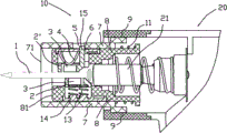
如图1至图3所示,本发明的电动榔头快夹装置10安装在电动榔头的击打头部20,该快夹装置包括两个用于夹紧及释放钉子1等紧固件的夹紧件2,2′,击打头部20内含往复运动击打轴21,击打轴21作用在钉子1等紧固件上,两个夹紧件2、2′上分别设有磁性部分3,两个夹紧件2、2′通过磁性部分3的相互吸引而具有夹紧钉子的夹紧位置(图2中所示位置),及通过磁性部分3的相互排斥而具有释放钉子的松开位置(图3中所示位置)。
As shown in Figures 1 to 3, the electric hammer quick-
如图5所示,磁性部分3由一个或数个N极磁性单元和一个或数个S极磁性单元组成, N极磁性单元和S极磁性单元相互间隔设置,在两夹紧件2、2′夹紧位置处,设置在其中一个夹紧件2′上的磁性部分3的N极、S极磁性单元分别与设置在另一个夹紧件2上的磁性部分3的S极、N极一一对应,在两夹紧件2、2′松开位置处,设置在其中一个夹紧件2′上的磁性部分3的N极、S极磁性单元分别与设置在另一个夹紧件2上的磁性部分3的N极、S极一一对应。
As shown in Figure 5, the
结合图2至图4可知,两个夹紧件2、2′在沿击打轴21往复运动方向上具有相对位移,从而使得N极、S极相互间隔的磁性部分3能够相互吸引而带动夹紧件2、2′夹持钉子,或者相互排斥而带动夹紧件2、2′松开钉子,本发明为使其中一个夹紧件2′能够相对另一个轴向固定的夹紧件2沿击打轴21往复运动方向上产生相对移动,还设置了一外套管7,该外套管7可移动地连接于击打头部20,该外套管7上设置与击打轴21往复运动方向平行的第一长孔5,该其中一个夹紧件2′上设置一穿过该第一长孔5并可沿该第一长孔5滑动的滑动臂15。外套管7内套装有一内套管8,该内套管8上设置与击打轴21往复运动方向平行的第二长孔6,该其中一个夹紧件2′上设置的滑动臂15穿过此第二长孔6并可在此第二长孔6内滑动,第一长孔5的长度大致等于外套管的前端面71与工件表面接触到外套管7将要带动内套管8一起向击打头部20内缩进的夹持钉子阶段中钉子被打进工件的深度,第二长孔6主要提供该其中一个夹紧件2′在沿内套筒8轴向上第一位置到第二位置之间的距离,此距离实质上为两个夹紧件2、2′的磁性部分3异性磁极对应到同性磁极对应时的在击打轴21往复运动方向上的相对位移,如前述位置关系可知,外套管的前端面71突出于内套管的前端面81,其突出距离等于或优选大于第一位置和第二位置之间的距离,本实施方式中,外套管7外还套接一套管支撑部件9,外套管7可在套管支撑部件9内伸缩,套管支撑部件9通过螺钉等紧固件固定到电动榔头击打头部20的机壳上,另外,在外套管7和内套管8之间有一偏置弹性元件11,用于将外套管7自动复位。
2 to 4, it can be seen that the two
结合图2至图4可知,两个夹紧件2、2′从夹紧位置到松开位置除了具有在沿击打轴21往复运动方向上的相对位移外,还具有沿垂直击打轴21往复运动方向上的位移,为实现该目的,本发明将两个夹紧件2、2′分别可移动地安装于内套管8上对称设置的径向孔16内,并且分别由以弹片形式提供的第一偏压元件4及以弹簧形式提供的第二偏压元件13支撑。为夹持钉子牢靠,两个夹紧件夹持钉子的表面均设有V型槽17,为了使钉子等紧固件完全打入工件,击打轴21需从两夹紧件2、2′之间通过,为减小该通过的阻力, 在夹紧件2、2′靠近击打轴21的侧面设有导向斜面18。另外设置有封装盖14 用于将夹紧件2、2′偏压元件等封装于内套管8 中。
2 to 4, it can be seen that the two
本实施方式中的夹紧件不限于两个,为夹紧更牢靠,可相应增加夹紧件的个数。 The clamping parts in this embodiment are not limited to two, and the number of clamping parts can be increased correspondingly for more secure clamping.
本实施方式的电动榔头快夹装置工作原理如下: The working principle of the electric hammer quick-clamping device in this embodiment is as follows:
装夹钉子时,克服偏置弹性元件11推动外套管7,当外套管7上的第一长孔5的左侧抵住其中一个夹紧件2′上的滑动臂15,再次推动外套管7,使两个夹紧件2、2′达到松开位置,此时分别设置在两个夹紧件2、2′上的磁性元件3的相同极性的磁性单元相对应,在同性相斥的作用下,两个夹紧件2、2′分别克服各自的弹性偏压元件4、13的作用相向移动至最大距离。此时可以放入钉子1,移除对外套管7的施加载荷,偏置元件11的开始复位,外套管7在偏置元件11的作用下准备复位,外套管7上的第一长孔5的右侧抵住其中一个夹紧件2′上的滑动臂15,使两个夹紧件2、2′上的磁性元件3的相异极性的磁性单元相对应,在异性相吸的作用下,两个夹紧件2、2′相互吸在一起,从而夹紧钉子。
When clamping the nail, overcome the bias
工作时,外套管7前端碰到工件,向支撑部件9内缩进,直至使两个夹紧件2、2′处于松开位置,此时两个夹紧件2、2′分离至最大距离,钉子1 和击打轴21都能通过内套管8。工作完毕后,由于工件对外套管7的施加载荷已经移除,快夹装置10恢复到初始状态。
When working, the front end of the
图6至图10为本发明的另一种实施方式图,与第一种实施方式一样,本夹紧装置也包括一外套管7,外套管7可移动的连接于击打头部20,外套管7外套接一套管支撑部件9,外套管7内套接一内套管8,内套管8上安装有用于夹紧及释放钉子1等紧固件的夹紧件2、2′。
6 to 10 are diagrams of another embodiment of the present invention. Like the first embodiment, the clamping device also includes an
与第一种实施方式不同的是,本夹紧件2、2′上分别设置有磁性元件31、31′,其中的一个磁性元件31面向内套管8中心的那一端磁极极性始终保持不变,而另一个磁性元件31′上连接有一齿轮结构,该齿轮与一齿条32啮合连接,齿条32上设置两个外伸臂35,该外伸臂35连接到外套管7上,因而,能够通过外套管7相对内套管8的移动带动齿条32在沿内套管8的轴向方向上的第一位置及第二位置之间移动,进而齿轮旋转使得其中的一个磁性元件31′的磁极极性翻转,由夹紧位置处的两个夹紧件2、2′上的磁性元件31、31′异极磁性相对翻转到松开位置处的两个夹紧件2、2′上的磁性元件31、31′的同性磁极相对。
The difference from the first embodiment is that the clamping
外套管的前端面71突出于内套管8的前端面81,在打钉过程中,工件的表面首先接触到外套管7的前端面71,对比图6、图7可知,该突出距离应当满足齿条32在第一位置及第二位置之间移动的距离。
The
夹紧件2、2′可相对内套管8径向移动地安装在内套管8上,夹紧件2、2′上设置有使夹紧件能够向内套管8中心偏压的偏压装置,本实施例中,作用在其中一个加紧件2′上的偏压装置为又一磁性元件33,该又一磁性元件33的磁极方向始终保持不变,因而,在所述其中的一个夹紧件2′上的磁性元件31′磁极磁性翻转过程中,该又一磁性元件33能够吸合或推开所述的磁性元件31′,作用在另一个夹紧件2上的偏压装置为一弹簧14。
The clamping
在其它实施方式中,磁性元件和夹紧件也可以是一体的,另外为实现这种通过极性翻转而夹紧及松开的目的,也不局限于在夹紧件上设置磁性元件,也可以是能够实现相同目的的磁性感应导电线圈等。 In other embodiments, the magnetic element and the clamping piece can also be integrated. In addition, in order to achieve the purpose of clamping and loosening through polarity reversal, it is not limited to the magnetic element on the clamping piece, and also It could be a magnetic induction conductive coil or the like that can achieve the same purpose.
Claims (2)
Priority Applications (6)
| Application Number | Priority Date | Filing Date | Title |
|---|---|---|---|
| CN201010166104.1A CN102233563B (en) | 2010-04-30 | 2010-04-30 | Quick clamping device for electric hammer |
| DE202011000093U DE202011000093U1 (en) | 2010-01-15 | 2011-01-14 | Quick release mechanism for electric hammer |
| GB1100594A GB2477028A (en) | 2010-01-15 | 2011-01-14 | Quick-clamping mechanism for electric hammer |
| US13/006,553 US8678262B2 (en) | 2010-01-15 | 2011-01-14 | Quick-clamping mechanism for electric hammer |
| CA2728290A CA2728290A1 (en) | 2010-01-15 | 2011-01-14 | Quick-clamping mechanism for electric hammer |
| FR1150309A FR2955283B3 (en) | 2010-01-15 | 2011-01-14 | QUICK CLAMPING MECHANISM FOR ELECTRIC HAMMER |
Applications Claiming Priority (1)
| Application Number | Priority Date | Filing Date | Title |
|---|---|---|---|
| CN201010166104.1A CN102233563B (en) | 2010-04-30 | 2010-04-30 | Quick clamping device for electric hammer |
Publications (2)
| Publication Number | Publication Date |
|---|---|
| CN102233563A CN102233563A (en) | 2011-11-09 |
| CN102233563B true CN102233563B (en) | 2014-06-11 |
Family
ID=44884935
Family Applications (1)
| Application Number | Title | Priority Date | Filing Date |
|---|---|---|---|
| CN201010166104.1A Expired - Fee Related CN102233563B (en) | 2010-01-15 | 2010-04-30 | Quick clamping device for electric hammer |
Country Status (1)
| Country | Link |
|---|---|
| CN (1) | CN102233563B (en) |
Families Citing this family (1)
| Publication number | Priority date | Publication date | Assignee | Title |
|---|---|---|---|---|
| CN104308812B (en) * | 2014-10-14 | 2016-02-03 | 张家港市创基机械设备制造有限公司 | For the impact head of electric hammer |
Citations (5)
| Publication number | Priority date | Publication date | Assignee | Title |
|---|---|---|---|---|
| DE3331866A1 (en) * | 1983-09-03 | 1985-03-21 | Metabowerke GmbH & Co, 7440 Nürtingen | DRILLING HAMMER |
| US6598775B1 (en) * | 2002-08-30 | 2003-07-29 | Tung-Hsien Chen | Hammer head assembly for power hammer |
| CN2588351Y (en) * | 2002-09-28 | 2003-11-26 | 义乌市易开盖实业公司 | Magnetic clamp |
| DE202004017883U1 (en) * | 2004-11-18 | 2006-03-23 | Weha - Ludwig Werwein Gmbh | Pneumatically operated hammer in particular for stone mason, comprising tool clamping area with magnetic elements |
| CN201389856Y (en) * | 2008-11-14 | 2010-01-27 | 王廷廷 | Clamping mechanism of automatic equipment |
Family Cites Families (4)
| Publication number | Priority date | Publication date | Assignee | Title |
|---|---|---|---|---|
| JP3301243B2 (en) * | 1994-11-25 | 2002-07-15 | 日立工機株式会社 | Tool holding device for driving machine |
| JPH09300240A (en) * | 1996-05-10 | 1997-11-25 | Hitachi Koki Co Ltd | Tool holding device for driving machine |
| JPH11333755A (en) * | 1998-05-21 | 1999-12-07 | Makita Corp | Nail holding device of nail driving machine |
| EP1773545A2 (en) * | 2004-07-23 | 2007-04-18 | Gavin Beales | Nailer device |
-
2010
- 2010-04-30 CN CN201010166104.1A patent/CN102233563B/en not_active Expired - Fee Related
Patent Citations (5)
| Publication number | Priority date | Publication date | Assignee | Title |
|---|---|---|---|---|
| DE3331866A1 (en) * | 1983-09-03 | 1985-03-21 | Metabowerke GmbH & Co, 7440 Nürtingen | DRILLING HAMMER |
| US6598775B1 (en) * | 2002-08-30 | 2003-07-29 | Tung-Hsien Chen | Hammer head assembly for power hammer |
| CN2588351Y (en) * | 2002-09-28 | 2003-11-26 | 义乌市易开盖实业公司 | Magnetic clamp |
| DE202004017883U1 (en) * | 2004-11-18 | 2006-03-23 | Weha - Ludwig Werwein Gmbh | Pneumatically operated hammer in particular for stone mason, comprising tool clamping area with magnetic elements |
| CN201389856Y (en) * | 2008-11-14 | 2010-01-27 | 王廷廷 | Clamping mechanism of automatic equipment |
Also Published As
| Publication number | Publication date |
|---|---|
| CN102233563A (en) | 2011-11-09 |
Similar Documents
| Publication | Publication Date | Title |
|---|---|---|
| US8424734B2 (en) | Clamping mechanism for an auto hammer | |
| AU2010101287A4 (en) | Auto Hammer | |
| WO2006008546A3 (en) | Nailer device | |
| US8678262B2 (en) | Quick-clamping mechanism for electric hammer | |
| PL1737616T3 (en) | Powered hand tool comprising a clamping device for a tool | |
| CN211681905U (en) | electric hammer | |
| CN102069480B (en) | Powered hammer | |
| CN102233563B (en) | Quick clamping device for electric hammer | |
| CN110113929B (en) | Quick release electronic information board holder | |
| AU2010101281A4 (en) | Auto Hammer | |
| CN105563178A (en) | Shaft-shaped part clamp | |
| CN201604134U (en) | Electric hammer quick clamping mechanism | |
| CA2591343A1 (en) | Magnet-force clamping apparatus | |
| CN109434535A (en) | Electromagnetic piston type tool changing device | |
| WO2005042210A1 (en) | Driver screw holder | |
| AU2010101288A4 (en) | Auto Hammer | |
| CN2654284Y (en) | Telescopic structure of hand tools | |
| CN208914143U (en) | A kind of motor fixture with magnetic attraction function | |
| CN205254126U (en) | Get device that reloads | |
| CN107659886B (en) | A device for assembling rubber parts and hard parts | |
| AU2010101285A4 (en) | Auto Hammer | |
| JP2011173206A (en) | Staple driving machine | |
| KR100562708B1 (en) | Screw guide tool for screwdriver | |
| CN106003109A (en) | Manipulator clamp holder assembling structure | |
| TW200800509A (en) | Ratchet wrench |
Legal Events
| Date | Code | Title | Description |
|---|---|---|---|
| C06 | Publication | ||
| PB01 | Publication | ||
| C10 | Entry into substantive examination | ||
| SE01 | Entry into force of request for substantive examination | ||
| C14 | Grant of patent or utility model | ||
| GR01 | Patent grant | ||
| CF01 | Termination of patent right due to non-payment of annual fee | ||
| CF01 | Termination of patent right due to non-payment of annual fee |
Granted publication date: 20140611 Termination date: 20170430 |