CN102230812B - Device and method for measuring return flow of L-shaped communicating pipe drilling liquid - Google Patents
Device and method for measuring return flow of L-shaped communicating pipe drilling liquid Download PDFInfo
- Publication number
- CN102230812B CN102230812B CN 201110086020 CN201110086020A CN102230812B CN 102230812 B CN102230812 B CN 102230812B CN 201110086020 CN201110086020 CN 201110086020 CN 201110086020 A CN201110086020 A CN 201110086020A CN 102230812 B CN102230812 B CN 102230812B
- Authority
- CN
- China
- Prior art keywords
- communicating pipe
- pipeline
- pipe
- type communicating
- oviduct
- Prior art date
- Legal status (The legal status is an assumption and is not a legal conclusion. Google has not performed a legal analysis and makes no representation as to the accuracy of the status listed.)
- Expired - Fee Related
Links
- 238000005553 drilling Methods 0.000 title claims abstract description 73
- 239000007788 liquid Substances 0.000 title claims abstract description 61
- 238000000034 method Methods 0.000 title claims abstract description 14
- 230000003287 optical effect Effects 0.000 claims abstract description 20
- 239000012530 fluid Substances 0.000 claims description 56
- 238000005259 measurement Methods 0.000 claims description 27
- 210000003101 oviduct Anatomy 0.000 claims 15
- 210000001364 upper extremity Anatomy 0.000 claims 2
- 238000004088 simulation Methods 0.000 claims 1
- 238000007781 pre-processing Methods 0.000 abstract description 11
- 230000003750 conditioning effect Effects 0.000 abstract description 9
- 238000001514 detection method Methods 0.000 abstract description 9
- 230000015572 biosynthetic process Effects 0.000 description 4
- 239000002245 particle Substances 0.000 description 4
- 238000010586 diagram Methods 0.000 description 3
- 238000005516 engineering process Methods 0.000 description 3
- 230000008878 coupling Effects 0.000 description 2
- 238000010168 coupling process Methods 0.000 description 2
- 238000005859 coupling reaction Methods 0.000 description 2
- 230000000694 effects Effects 0.000 description 2
- 230000009545 invasion Effects 0.000 description 2
- 238000000691 measurement method Methods 0.000 description 2
- 239000007787 solid Substances 0.000 description 2
- 239000007790 solid phase Substances 0.000 description 2
- 229910000831 Steel Inorganic materials 0.000 description 1
- 238000009825 accumulation Methods 0.000 description 1
- 230000003321 amplification Effects 0.000 description 1
- 230000009286 beneficial effect Effects 0.000 description 1
- 238000004364 calculation method Methods 0.000 description 1
- 230000000739 chaotic effect Effects 0.000 description 1
- 230000003628 erosive effect Effects 0.000 description 1
- 238000001914 filtration Methods 0.000 description 1
- 230000006698 induction Effects 0.000 description 1
- 238000009434 installation Methods 0.000 description 1
- 238000002955 isolation Methods 0.000 description 1
- 230000033001 locomotion Effects 0.000 description 1
- 239000000203 mixture Substances 0.000 description 1
- 238000003199 nucleic acid amplification method Methods 0.000 description 1
- 230000002265 prevention Effects 0.000 description 1
- 238000011897 real-time detection Methods 0.000 description 1
- 238000010992 reflux Methods 0.000 description 1
- 238000005070 sampling Methods 0.000 description 1
- 230000008054 signal transmission Effects 0.000 description 1
- 239000010959 steel Substances 0.000 description 1
Images


Landscapes
- Earth Drilling (AREA)
- Measuring Volume Flow (AREA)
Abstract
Description
一、 技术领域: 1. Technical field:
本发明涉及的是在石油天然气钻井随钻检测领域中溢流快速识别技术,具体涉及的是L型连通管钻井液返出流量测量装置及其测量方法。 The invention relates to a rapid overflow identification technology in the field of oil and gas drilling detection while drilling, in particular to an L-shaped connecting pipe drilling fluid return flow measuring device and a measuring method thereof.
二、 背景技术: 2. Background technology:
石油天然气资源钻井过程中如果地层压力大于井内钻井液压力将会出现地层流体侵入井眼的现象,称为溢流,如果处理不当将会导致井喷甚至失去控制,造成恶性安全事故。预防井喷的关键是及时发现溢流,溢流发现越早,溢流量越小,处理溢流的难度也越小,发生井喷的概率就越低,这就要求钻井现场溢流检测装置做出快速准确的预警,及时关井,重新建立压力平衡。 During the drilling of oil and gas resources, if the formation pressure is greater than the drilling fluid pressure in the well, formation fluid will invade the wellbore, which is called overflow. If it is not handled properly, it will lead to blowout or even loss of control, resulting in vicious safety accidents. The key to preventing blowout is to detect overflow in time. The earlier the overflow is found, the smaller the overflow, the less difficult it is to deal with the overflow, and the lower the probability of blowout. Accurate early warning, timely shutdown, and re-establishment of pressure balance.
与溢流检测相关的井口防喷装备通常由防喷器、喇叭管(溢流管)、喇叭管开窗(返出口)、钻井液返出管线(海洋钻井平台亦称高架槽)和钻井液池构成。 The wellhead blowout prevention equipment related to overflow detection usually consists of blowout preventer, trumpet pipe (overflow pipe), trumpet pipe window (return outlet), drilling fluid return pipeline (offshore drilling platform is also called elevated tank) and drilling fluid pool composition.
钻井现场普遍应用的溢流检测方法是钻井液池液位检测方法,该方法通过观察或测量钻井液池内液面高度变化来估计钻井液总量增减,判断是否有地层流体侵入。但该方法有以下问题,一是在较小溢流量时,因钻井液池底面积较大,液面高度变化不明显。二是侵入的流体需流经返出管线后到钻井池积累,体积积累效应导致报警延迟。另外为保证钻井液在池内不发生沉淀,需应用搅拌器,搅拌器旋转导致池内液面波动,严重影响测量精度和溢流预警时间。 The overflow detection method commonly used in the drilling site is the liquid level detection method of the drilling fluid pool. This method estimates the increase or decrease of the total amount of drilling fluid by observing or measuring the change of the liquid level in the drilling fluid pool, and judges whether there is formation fluid invasion. But this method has the following problems, one is when the overflow is small, because the bottom area of the drilling fluid pool is large, the change of the liquid level is not obvious. The second is that the intruding fluid needs to flow through the return pipeline and accumulate in the drilling pool, and the volume accumulation effect causes the delay of the alarm. In addition, in order to ensure that the drilling fluid does not settle in the pool, it is necessary to use an agitator. The rotation of the agitator causes the liquid level in the pool to fluctuate, which seriously affects the measurement accuracy and overflow warning time.
另一种精度较高的溢流检测方法是流量差法,该方法分别测量泵入井内和返出的钻井液流量,并依据其差值判断溢流或井漏,泵入井内的钻井液流量可以通过泵冲计数器较精确的获得,但在井口处测量返出流量却非常困难,原因是喇叭管返出口存在自由液面(非有压管路)和方钻杆旋转等因素影响,该方法无法在常规钻机上普及,仅有少数具备全封闭钻井液循环系统的钻机(如控压钻井系统)才能实现流量差法溢流检测。 Another overflow detection method with high precision is the flow difference method, which measures the flow rate of the drilling fluid pumped into the well and returned, and judges the overflow or lost circulation according to the difference value, and the flow rate of the drilling fluid pumped into the well It can be obtained more accurately by the pump stroke counter, but it is very difficult to measure the return flow at the wellhead because of the influence of factors such as the free liquid surface (non-pressurized pipeline) and the rotation of the kelly at the return port of the trumpet tube. It cannot be popularized on conventional drilling rigs, and only a few drilling rigs with fully enclosed drilling fluid circulation systems (such as managed pressure drilling systems) can realize the overflow detection of flow difference method.
常规钻机喇叭管内直接测量钻井液返出流量的难点: Difficulties in directly measuring the return flow rate of drilling fluid in the trumpet tube of conventional drilling rig:
一、应用接触式流量测量仪器(如涡轮流量计) First, the application of contact flow measuring instruments (such as turbine flowmeters)
应用该类型流量计需要下至喇叭管内,与环空的钻井液直接接触测量。问题主要以下两点: The application of this type of flowmeter needs to go down into the trumpet tube and directly contact the drilling fluid in the annular space for measurement. The problem is mainly the following two points:
①由于更换钻头、固井、电测等作业时需要起下钻柱,钻柱或钻头很难避免与管内测量仪器发生碰撞。 ① Due to the need to trip the drill string during operations such as drill bit replacement, cementing, and electrical testing, it is difficult to avoid collisions between the drill string or the drill bit and the measuring instruments in the pipe.
②因为环空(指方钻杆或钻杆与喇叭管之间的环形空间)中钻井液存在自由液面、方钻杆或钻杆(顶驱时为钻杆)高速旋转、喇叭管存在横向返出口等因素影响,导致钻井液在喇叭管内产生带有横向开窗的环空螺旋流,速度为周向和轴向速度的耦合,流动规律及其复杂。我们期望能得到的轴向平均速度而精确计算出返出流量,但轴向速度仅仅是环空螺旋流速度的一个分量,目前任何接触式测量仪器测量的均是耦合速度,还无法直接测量轴向速度。 ②Because there is a free liquid surface in the drilling fluid in the annular space (referring to the annular space between the kelly or the drill pipe and the trumpet), the high-speed rotation of the kelly or the drill pipe (drill pipe in the case of top drive), and the transverse Influenced by factors such as the return port, the drilling fluid produces an annular spiral flow with transverse windows in the horn tube, and the velocity is the coupling of the circumferential and axial velocities, and the flow law is extremely complex. We expect to obtain the axial average velocity to accurately calculate the return flow, but the axial velocity is only a component of the annular spiral flow velocity. At present, any contact measuring instrument measures the coupling velocity and cannot directly measure the axial velocity. towards speed.
二、非接触式流量测量仪器 2. Non-contact flow measuring instrument
目前常用于钻井工业的非接触式流量测量仪器有以下三大类: There are three categories of non-contact flow measuring instruments commonly used in the drilling industry:
①电磁流量计:目前该类流量计还无法测量喇叭管内的环空螺旋流流量,这是其工作原理所决定的,其原理是流体流动过程中切割磁感线产生电信号,转换为流量信息。但由于喇叭管内的方钻杆(或钻杆)内钻井液竖直向下流动,环空返出的钻井液为螺旋流向上流动,也就是说喇叭管内同时存在同时向上和向下流动的流体,其切割磁场产生的电信号混乱,无法识别。 ① Electromagnetic flowmeter: At present, this type of flowmeter cannot measure the annular spiral flow flow in the horn tube, which is determined by its working principle. The principle is that the electric signal generated by cutting the magnetic induction line during the fluid flow process is converted into flow information . However, since the drilling fluid in the kelly (or drill pipe) in the horn tube flows vertically downward, the drilling fluid returned from the annular space flows upward in a spiral flow, that is to say, there are simultaneously upward and downward fluids in the horn tube , the electrical signal generated by its cutting magnetic field is chaotic and cannot be recognized.
②超声波多普勒流量计:超声波多普勒流量原理是测量发射和遇到固体颗粒反射的超声波频率差,这个频率差是流体中固体颗粒运动而产生的声波多普勒频移,正比于流体流速,进而换算可以得到流体的流量。该类流量计无法测量喇叭管内钻井液返出流量的原因是方钻杆或钻杆旋转导致钻井液内的固相颗粒周向运动速度远高于轴向运动速度,所以该流量计测量出的固相颗粒流速并非我们期望得到的轴向流速,换算出的结果也并不是真实返出流量。 ②Ultrasonic Doppler flowmeter: The principle of ultrasonic Doppler flow is to measure the frequency difference of ultrasonic waves emitted and reflected by solid particles. This frequency difference is the acoustic Doppler frequency shift generated by the movement of solid particles in the fluid, which is proportional to the fluid The flow rate can be converted to obtain the flow rate of the fluid. The reason why this type of flowmeter cannot measure the return flow rate of the drilling fluid in the horn tube is that the rotation of the kelly or the drill pipe causes the solid phase particles in the drilling fluid to move at a much higher speed in the circumferential direction than in the axial direction, so the flow rate measured by the flowmeter is The flow rate of solid phase particles is not the axial flow rate we expect, and the converted result is not the true return flow rate.
②液位传感器(光学,超声波):一是防碰问题依然很难克服,另外因方钻杆高速旋转导致的自由液面波动问题给喇叭管内测量带来了非常大的困难,旋转导致喇叭管内钻井液液面呈现凹状,凹陷深度随方钻杆转数增加而加深,这就导致光学或超声波液位传感器无法准确识别液面变化是由溢流引起还是方钻杆旋转引起。 ②Liquid level sensor (optical, ultrasonic): First, the anti-collision problem is still difficult to overcome. In addition, the free liquid level fluctuation problem caused by the high-speed rotation of the kelly brings great difficulties to the measurement in the horn tube, and the rotation causes The drilling fluid surface is concave, and the depth of the depression deepens with the increase of the kelly rotation, which makes it impossible for optical or ultrasonic liquid level sensors to accurately identify whether the liquid level change is caused by overflow or kelly rotation.
三、发明内容: 3. Contents of the invention:
本发明的一个目的是提供一种L型连通管钻井液返出流量测量装置,本发明的另一个目的是提供这种L型连通管钻井液返出流量测量装置的测量方法,它用于解决现有钻井液返出流量无法在井口位置实现精确测量的问题,在常规钻机上实现流量差法溢流快速识别。 One object of the present invention is to provide a kind of L-type connecting pipe drilling fluid return flow measuring device, another object of the present invention is to provide the measurement method of this L-shaped connecting pipe drilling fluid return flow measuring device, it is used to solve The problem that the existing drilling fluid return flow cannot be accurately measured at the wellhead position, and the rapid identification of overflow by the flow difference method can be realized on the conventional drilling rig.
本发明解决其技术问题所采用的技术方案是:这种L型连通管钻井液返出流量测量装置由光学液位传感器、L型连通管、喇叭管、连通管托架、信号调理与预处理装置、数据采集单元、客户端计算机、声光报警装置组成,喇叭管管线加装L型连通管,L型连通管与喇叭管共同构成连通器;L型连通管开窗口垂向位置位于喇叭管管线法兰盘与返出管线下缘之间;L型连通管开窗口周向方位以返出管线与喇叭管管线的交线为始边,逆时针旋转至返出管线中心线的延长线之间,光学液位传感器安装在L型连通管托架上。 The technical solution adopted by the present invention to solve the technical problem is: this L-shaped connecting pipe drilling fluid return flow measuring device consists of an optical liquid level sensor, an L-shaped connecting pipe, a trumpet pipe, a connecting pipe bracket, signal conditioning and preprocessing Device, data acquisition unit, client computer, and sound and light alarm device. The horn pipe pipeline is equipped with an L-shaped connecting pipe. The L-shaped connecting pipe and the horn pipe together form a connector; the vertical position of the opening window of the L-shaped connecting pipe is located in the horn pipe. Between the pipeline flange and the lower edge of the return pipeline; the circumferential direction of the opening window of the L-shaped connecting pipe starts from the intersection line of the return pipeline and the trumpet pipe pipeline, and rotates counterclockwise to the extension line of the center line of the return pipeline In between, the optical liquid level sensor is installed on the L-shaped connecting pipe bracket.
上述方案中L型连通管开窗口垂向位置靠近法兰盘处,以避免受到喇叭管内方钻杆旋转影响。 In the above scheme, the vertical position of the opening window of the L-shaped connecting pipe is close to the flange, so as to avoid being affected by the rotation of the kelly in the trumpet pipe.
上述方案中L型连通管与喇叭管之间设置返流管,返流管与L型连通管的夹角在0°到45°之间,返流管在喇叭管上开窗口垂向位置位于返出管线上缘之上,返流管开窗口周向方位以返出管线与喇叭管管线的交线为始边,逆时针旋转至返出管线中心线的延长线之间。当流量过大时,L型连通管内液体将从返流管返流回喇叭管内,避免钻井液冲向光学液位传感器,损坏仪器。 In the above scheme, a return pipe is set between the L-shaped connecting pipe and the trumpet pipe. The angle between the return pipe and the L-shaped connecting pipe is between 0° and 45°. The vertical position of the return pipe on the trumpet pipe is located at Above the upper edge of the return pipeline, the circumferential direction of the window opening of the return pipe starts from the intersection line of the return pipeline and the trumpet pipe line, and rotates counterclockwise to the extension line of the center line of the return pipeline. When the flow rate is too large, the liquid in the L-shaped connecting pipe will return from the return pipe to the trumpet pipe to prevent the drilling fluid from rushing to the optical liquid level sensor and damaging the instrument.
上述方案中L型连通管底部水平管处安装排泥管,排泥管中安装活塞除泥器。这样可防止喇叭管下开窗口出现泥堵,当出现泥堵时,通过手动或液压活塞除泥器除泥即可。 In the above scheme, a mud discharge pipe is installed at the horizontal pipe at the bottom of the L-shaped connecting pipe, and a piston desilter is installed in the mud discharge pipe. This can prevent mud blockage in the lower window of the trumpet tube. When mud blockage occurs, it can be removed by manual or hydraulic piston desilter.
上述L型连通管钻井液返出流量测量装置的测量方法,通过实时检测L型连通管内的液面高度得到钻井液返出流量,具体如下: The measurement method of the above-mentioned L-shaped connecting pipe drilling fluid return flow measuring device is to obtain the drilling fluid return flow by real-time detection of the liquid level height in the L-shaped connecting pipe, as follows:
步骤一:在喇叭管靠近法兰盘位置开窗打圆形孔,加装L型连通管,使喇叭管与L型连通管共同构成连通器,L型连通管下开窗口轴向位置位于喇叭管法兰盘与返出管线下缘之间,应尽可能靠近法兰盘; L型连通管上下开窗口周向方位以返出管线与喇叭管管线的交线为始边,逆时针旋转至返出管线中心线的延长线之间; Step 1: Open a window at the position of the horn tube close to the flange and make a circular hole, add an L-shaped connecting pipe, so that the horn tube and the L-shaped connecting pipe together form a connecting device, and the axial position of the window opened under the L-shaped connecting pipe is located at the horn Between the pipe flange and the lower edge of the return pipeline, it should be as close as possible to the flange; the upper and lower opening windows of the L-shaped connecting pipe start from the intersection line of the return pipeline and the trumpet pipe line, and rotate counterclockwise to Return between the extension lines of the center line of the pipeline;
步骤二:将光学液位传感器安装在L型连通管托架处; Step 2: Install the optical liquid level sensor on the L-shaped connecting pipe bracket;
步骤三:步骤二中传感器实时测量L型连通管内液面高度,并输出模拟辅助变量信号至信号调理与预处理装置;
Step 3: In
步骤四:信号调理与预处理装置将步骤三信号预处理后输出数字辅助变量信号;
Step 4: The signal conditioning and preprocessing device outputs the digital auxiliary variable signal after preprocessing the signal in
步骤五:数据采集单元实时采集数字辅助变量信号,并输入辅助变量数据至客户端计算机; Step 5: The data acquisition unit collects the digital auxiliary variable signal in real time, and inputs the auxiliary variable data to the client computer;
步骤六:客户端计算机的软测量系统计算得到钻井液出口流量Q值,并依据Q值判断是否启动声光报警装置。 Step 6: The soft measurement system of the client computer calculates the Q value of the drilling fluid outlet flow rate, and judges whether to activate the sound and light alarm device according to the Q value.
有益效果: Beneficial effect:
1.本发明在井队现有井口装置上进行改进,在喇叭管上加装L型连通管,与喇叭管形成连通器。通过测量L型连通管内液位高度间接非接触式测量钻井液返出流量,与钻井液池液位检测法相比预警时间大幅度提前,检测精度大幅提高,能够给钻井现场工作人员更充裕的时间关井,有效地预防井喷事故发生,该发明实时检测溢流的同时亦可监测钻进过程中井漏是否发生。 1. The present invention improves the existing wellhead device of the well team, and installs an L-shaped connecting pipe on the trumpet pipe to form a communicator with the trumpet pipe. By measuring the liquid level height in the L-shaped connecting pipe, the indirect non-contact measurement of the drilling fluid return flow rate is greatly advanced compared with the drilling fluid pool liquid level detection method, and the detection accuracy is greatly improved, which can give the drilling site staff more time. Shut down the well to effectively prevent blowout accidents. The invention detects overflow in real time and can also monitor whether lost circulation occurs during drilling.
2.本发明将L型连通管液位测量与钻井液返出流量结合起来,通过实时测量L型连通管液位变化就可以实时监测泵入和返出的钻井液流量差,准确早期地判断是否发生溢流,是突破目前溢流快速识别瓶颈的一项重大的技术探索。 2. The invention combines the liquid level measurement of the L-shaped connecting pipe with the return flow rate of the drilling fluid. By measuring the liquid level change of the L-shaped connecting pipe in real time, the flow difference between the pumped and returned drilling fluid can be monitored in real time, and it can be accurately and early judged whether there is a Overflow is a major technical exploration to break through the current bottleneck of rapid identification of overflow.
3.本发明应用的L型连通管方案解决了因起下钻柱与测量仪器防碰问题。 3. The L-shaped connecting pipe scheme applied in the present invention solves the problem of anti-collision between the drill string and the measuring instrument due to tripping.
4.通过L型连通管液位测量钻井液返出流量,解决了方钻杆或钻杆旋转引起自由液面波动而影响返出流量测量精度的问题。 4. The return flow of drilling fluid is measured through the liquid level of the L-shaped connecting pipe, which solves the problem that the fluctuation of the free liquid surface caused by the rotation of the kelly or the drill pipe affects the measurement accuracy of the return flow.
5.本发明选用的光学液位传感器安装在带有反流管结构的L型连通管顶端,连续测量L型连通管内液位高度,不与钻井液接触,即使流量变化较大也不会造成钻井液冲蚀仪器,影响测量精度。 5. The optical liquid level sensor selected by the present invention is installed on the top of the L-shaped connecting pipe with a reflux pipe structure, continuously measures the liquid level height in the L-shaped connecting pipe, does not contact the drilling fluid, and will not cause drilling fluid damage even if the flow rate changes greatly. Erosion of the instrument will affect the measurement accuracy.
6.避免目前喇叭管内直接测量返出流量所涉及到的问题和测量难点。因L型连通管内钻井液不旋转,所以开窗口位置的压力直接决定了液面的高度,而开窗口越靠近法兰盘位置(远离自由液面)受到喇叭管内方钻杆旋转的影响越小,这种影响在满足工程精度要求时可以忽略不计或通过系数适当修正。当发生溢流时,井底增压,压力波传至连通器内时L型连通管内液面开始增高,光学液位传感器可以直接测量液位变化得到钻井液返出流量。 6. The problems and measurement difficulties involved in the direct measurement of the return flow in the current horn tube are avoided. Because the drilling fluid in the L-shaped connecting pipe does not rotate, the pressure at the opening position directly determines the height of the liquid level, and the closer the opening is to the flange (away from the free liquid surface), the less affected by the rotation of the kelly in the horn tube , this effect can be ignored or properly corrected by coefficients when meeting the engineering accuracy requirements. When an overflow occurs, the bottom of the well is pressurized, and the liquid level in the L-shaped connecting pipe begins to increase when the pressure wave is transmitted to the connector. The optical liquid level sensor can directly measure the change of the liquid level to obtain the return flow rate of the drilling fluid.
四、附图说明: 4. Description of drawings:
图1是本发明测量装置示意图; Fig. 1 is a schematic diagram of a measuring device of the present invention;
图2是本发明测量流程框图; Fig. 2 is a block diagram of the measurement process of the present invention;
图3是 L型连通管开窗口周向方位角度俯视示意图。 Fig. 3 is a schematic top view of the L-shaped connecting pipe with the window opening in the circumferential direction and azimuth angle.
1防喷器;2活塞除泥器;3 L型连通管开窗口;4 L型连通管;5 L型连通管内液位;6返流管开窗口;7返流管;8 L型连通管托架;9光学液位传感器;10方钻杆;11喇叭管;12喇叭管法兰盘;13喇叭管返出管线;14返出管线与喇叭管交线;15信号调理与预处理装置;16数据采集单元;17客户端计算机;18声光报警灯;19返出管线中心线;20 L型连通管开窗口周向方位角。 1. Blowout preventer; 2. Piston desilter; 3. Opening window of L-shaped connecting pipe; 4. L-shaped connecting pipe; 5. Liquid level in L-shaped connecting pipe; 6. Opening window of return pipe; Bracket; 9 optical liquid level sensor; 10 kelly; 11 horn tube; 12 horn tube flange; 13 horn tube return pipeline; 14 return pipeline and horn tube intersection line; 15 signal conditioning and preprocessing device; 16 data acquisition unit; 17 client computer; 18 sound and light alarm lights; 19 return pipeline center line; 20 L-shaped connecting pipe opening window circumferential azimuth.
五、具体实施方式: 5. Specific implementation methods:
下面结合附图对本发明做进一步的说明: Below in conjunction with accompanying drawing, the present invention will be further described:
如图1所示,本发明L型连通管钻井液返出流量测量装置由光学液位传感器9、L型连通管4、喇叭管11、L型连通管托架8、信号调理与预处理装置15、数据采集单元16、客户端计算机17、声光报警装置组成,目前,在石油钻井现场钻井液敞开式循环时,返出流量测量多为在井口处设置喇叭管11和环形防喷器1,喇叭管11和环形防喷器1在钻台平面下面,方钻杆10从喇叭管11穿出,喇叭管11处连接矩形槽,通过观察或测量矩形槽内液面高度变化来估计液体总量增减,判断是否有地层流体侵入。本发明与此不同,本发明在喇叭管11管线处加装L型连通管4,使喇叭管11与L型连通管4共同构成连通器,通过实时检测L型连通管内液位5高度得到钻井液返出流量,即将L型连通管4焊接在喇叭管11管线上,L型连通管开窗口3垂向位置位于喇叭管管线法兰盘12与返出管线13下缘之间,应尽可能靠近法兰盘12;结合图3所示,L型连通管开窗口3方位以返出管线13与喇叭管11管线的交线为始边,逆时针旋转至返出管线中心线19的延长线之间,即返出管线中心线19的反向延长线与返出管线13与喇叭管11管线的交线处之间的区域,该区间的最大夹角为L型连通管开窗口周向方位角20,L型连通管4可以任意设置在这个区间内,高精度光学液位传感器9安装在L型连通管托架8上;信号调理与预处理装置15、数字信号传输总线、数据采集单元16、客户端计算机17按照公知技术连接,声光报警装置为声光报警灯18。本发明中L型连通管4与喇叭管11之间设置返流管7,返流管7与L型连通管4的夹角在0°到45°之间,可避免钻井液冲向光学液位传感器9,损坏仪器。
As shown in Figure 1, the L-shaped connecting pipe drilling fluid return flow measurement device of the present invention consists of an optical liquid level sensor 9, an L-shaped connecting
图2是本发明测量流程框图,如图所示,这种L型连通管钻井液返出流量测量装置的测量方法通过实时检测L型连通管4内的液面高度得到钻井液返出流量,具体如下:
Fig. 2 is a measurement flow diagram of the present invention, as shown in the figure, the measuring method of this L-shaped communicating pipe drilling fluid return flow measurement device obtains the drilling fluid return flow by detecting the liquid level height in the L-shaped communicating
在喇叭管11靠近法兰盘12位置开窗打圆形孔,车丝扣,加装竖直小直径L型钢管连通管,与喇叭管11形成连通器,L型连通管4在喇叭管上开窗口轴向位置位于喇叭管法兰盘12与返出管线13下缘之间,应尽可能靠近法兰盘12;L型连通管开窗口3周向方位以返出管线13与喇叭管11管线的交线为始边,逆时针旋转至返出管线中心线19的延长线;再将高精度光学液位传感器9安装在L型连通管托架8处。安装后,高精度光学液位传感器9实时测量液面高度等辅助变量,输出模拟辅助变量信号至信号调理与预处理装置15,对模拟辅助变量信号进行放大、隔绝、滤波、运算等预处理,经信号调理与预处理装置15处理后输出数字辅助变量信号。数据采集单元16通过总线连接实时采集数字辅助变量信号,并通过客户端计算机17接口输入辅助变量数据至客户端计算机17。辅助变量数据经客户端计算机17的软测量系统计算得到钻井液出口流量Q值,最后客户端计算机17依据Q值是否达到报警上限执行是否启动声光报警灯18,软测量系统为软测量模型软件。软测量模型软件由以下关系确定,流量Q与液位高度H、转速N等参数有如下关系: 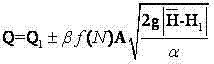


Claims (6)
Priority Applications (1)
| Application Number | Priority Date | Filing Date | Title |
|---|---|---|---|
| CN 201110086020 CN102230812B (en) | 2011-04-07 | 2011-04-07 | Device and method for measuring return flow of L-shaped communicating pipe drilling liquid |
Applications Claiming Priority (1)
| Application Number | Priority Date | Filing Date | Title |
|---|---|---|---|
| CN 201110086020 CN102230812B (en) | 2011-04-07 | 2011-04-07 | Device and method for measuring return flow of L-shaped communicating pipe drilling liquid |
Publications (2)
| Publication Number | Publication Date |
|---|---|
| CN102230812A CN102230812A (en) | 2011-11-02 |
| CN102230812B true CN102230812B (en) | 2013-04-17 |
Family
ID=44843400
Family Applications (1)
| Application Number | Title | Priority Date | Filing Date |
|---|---|---|---|
| CN 201110086020 Expired - Fee Related CN102230812B (en) | 2011-04-07 | 2011-04-07 | Device and method for measuring return flow of L-shaped communicating pipe drilling liquid |
Country Status (1)
| Country | Link |
|---|---|
| CN (1) | CN102230812B (en) |
Families Citing this family (6)
| Publication number | Priority date | Publication date | Assignee | Title |
|---|---|---|---|---|
| CN102704874A (en) * | 2012-05-18 | 2012-10-03 | 西南石油大学 | Device and method for detecting drilling fluid return flow |
| CN105114019A (en) * | 2015-05-29 | 2015-12-02 | 东北石油大学 | Double-arc curvilinear drilling fluid outlet flow measuring device and method |
| CN107288620B (en) * | 2017-08-24 | 2023-06-06 | 重庆科技学院 | Intelligent detection device for liquid level of oil drilling well head anti-overflow pipe drilling fluid |
| CN109538142A (en) * | 2018-12-31 | 2019-03-29 | 中石化石油工程技术服务有限公司 | One kind being used for indoor mud flow rate detection device and its detection method |
| CN109538143B (en) * | 2018-12-31 | 2023-10-20 | 中石化石油工程技术服务有限公司 | A drilling fluid outlet flow quantitative detection device and drilling fluid level measurement method |
| CN115218990A (en) * | 2022-08-23 | 2022-10-21 | 中石化绿源地热能开发有限公司 | Geothermal well liquid level measuring method and geothermal well liquid level measuring structure |
Citations (5)
| Publication number | Priority date | Publication date | Assignee | Title |
|---|---|---|---|---|
| US3963077A (en) * | 1975-06-18 | 1976-06-15 | Faulkner Ben V | Method of preventing well bore drilling fluid overflow and formation fluid blowouts |
| US4394880A (en) * | 1980-10-31 | 1983-07-26 | Faulkner Ben V | Method of preventing drill string overflow |
| CN101037940A (en) * | 2006-03-14 | 2007-09-19 | 刘志国 | System for detecting drilling fluids outlet flow |
| CN201180515Y (en) * | 2008-02-01 | 2009-01-14 | 滨州学院 | Automatic continuous grouting device for oilfield drilling and tripping |
| CN201292846Y (en) * | 2008-11-26 | 2009-08-19 | 中国石油天然气股份有限公司 | Oil gas well trace overflow real-time monitoring device |
-
2011
- 2011-04-07 CN CN 201110086020 patent/CN102230812B/en not_active Expired - Fee Related
Patent Citations (5)
| Publication number | Priority date | Publication date | Assignee | Title |
|---|---|---|---|---|
| US3963077A (en) * | 1975-06-18 | 1976-06-15 | Faulkner Ben V | Method of preventing well bore drilling fluid overflow and formation fluid blowouts |
| US4394880A (en) * | 1980-10-31 | 1983-07-26 | Faulkner Ben V | Method of preventing drill string overflow |
| CN101037940A (en) * | 2006-03-14 | 2007-09-19 | 刘志国 | System for detecting drilling fluids outlet flow |
| CN201180515Y (en) * | 2008-02-01 | 2009-01-14 | 滨州学院 | Automatic continuous grouting device for oilfield drilling and tripping |
| CN201292846Y (en) * | 2008-11-26 | 2009-08-19 | 中国石油天然气股份有限公司 | Oil gas well trace overflow real-time monitoring device |
Also Published As
| Publication number | Publication date |
|---|---|
| CN102230812A (en) | 2011-11-02 |
Similar Documents
| Publication | Publication Date | Title |
|---|---|---|
| CN102230812B (en) | Device and method for measuring return flow of L-shaped communicating pipe drilling liquid | |
| CN104712320B (en) | Gas cut early monitoring device and method in drilling process | |
| CN102121357A (en) | Drilling fluid return flow measuring method and measuring device thereof | |
| CN105864642B (en) | A kind of pipeline leakage testing device and detection method | |
| CN105507886B (en) | A kind of overflow and leakage monitoring system and its monitoring method | |
| KR20190108547A (en) | Apparatuses and methods for determining wellbore influx condition using qualitative indications | |
| CN111364979B (en) | Underground gas invasion monitoring system based on ultrasonic waves | |
| CN109538143B (en) | A drilling fluid outlet flow quantitative detection device and drilling fluid level measurement method | |
| CN100513736C (en) | Underground liquid level monitoring system and its method | |
| CN109403894A (en) | Early overflow and leakage monitoring system for well drilling | |
| CN105651349A (en) | Drilling fluid flow quantitative detection while drilling system and application thereof | |
| CN105756668B (en) | Leakage monitoring well kick system and monitoring method | |
| CN111364978A (en) | A kind of well kick and lost circulation monitoring device and monitoring method | |
| CN106609661A (en) | A drilling fluid flow detection device and method | |
| CN109707368B (en) | The method of overflow leakage early warning trend analysis is carried out in drilling well/tripping operation | |
| CN103277089A (en) | Well-drilling early overflow loss ground monitoring device | |
| CN103926422A (en) | Fluid measuring system and method | |
| CN105804724B (en) | An ultrasonic liquid level monitoring device for petroleum drilling | |
| CN202596621U (en) | Novel slurry outlet flow detection meter | |
| CN1970990B (en) | Method for measuring return flow in petroleum drilling and device therefor | |
| CN201180515Y (en) | Automatic continuous grouting device for oilfield drilling and tripping | |
| CN102704874A (en) | Device and method for detecting drilling fluid return flow | |
| CN206694020U (en) | The device of gas cut is monitored in real time using the pressure wave signal of measurement while drilling instrument | |
| CN209817986U (en) | Drilling fluid outlet flow quantitative detection device | |
| CN202900261U (en) | Drilling fluid overflowing monitoring device |
Legal Events
| Date | Code | Title | Description |
|---|---|---|---|
| C06 | Publication | ||
| PB01 | Publication | ||
| C10 | Entry into substantive examination | ||
| SE01 | Entry into force of request for substantive examination | ||
| C14 | Grant of patent or utility model | ||
| GR01 | Patent grant | ||
| CF01 | Termination of patent right due to non-payment of annual fee |
Granted publication date: 20130417 Termination date: 20180407 |
|
| CF01 | Termination of patent right due to non-payment of annual fee |