CN102196762A - An optical probe having a position measuring system - Google Patents
An optical probe having a position measuring system Download PDFInfo
- Publication number
- CN102196762A CN102196762A CN2009801430235A CN200980143023A CN102196762A CN 102196762 A CN102196762 A CN 102196762A CN 2009801430235 A CN2009801430235 A CN 2009801430235A CN 200980143023 A CN200980143023 A CN 200980143023A CN 102196762 A CN102196762 A CN 102196762A
- Authority
- CN
- China
- Prior art keywords
- light guide
- coil
- optical
- position measuring
- drive
- Prior art date
- Legal status (The legal status is an assumption and is not a legal conclusion. Google has not performed a legal analysis and makes no representation as to the accuracy of the status listed.)
- Granted
Links
Images


Classifications
-
- A—HUMAN NECESSITIES
- A61—MEDICAL OR VETERINARY SCIENCE; HYGIENE
- A61B—DIAGNOSIS; SURGERY; IDENTIFICATION
- A61B1/00—Instruments for performing medical examinations of the interior of cavities or tubes of the body by visual or photographical inspection, e.g. endoscopes; Illuminating arrangements therefor
- A61B1/00163—Optical arrangements
- A61B1/00188—Optical arrangements with focusing or zooming features
-
- A—HUMAN NECESSITIES
- A61—MEDICAL OR VETERINARY SCIENCE; HYGIENE
- A61B—DIAGNOSIS; SURGERY; IDENTIFICATION
- A61B1/00—Instruments for performing medical examinations of the interior of cavities or tubes of the body by visual or photographical inspection, e.g. endoscopes; Illuminating arrangements therefor
- A61B1/00064—Constructional details of the endoscope body
- A61B1/00071—Insertion part of the endoscope body
- A61B1/0008—Insertion part of the endoscope body characterised by distal tip features
- A61B1/00096—Optical elements
-
- A—HUMAN NECESSITIES
- A61—MEDICAL OR VETERINARY SCIENCE; HYGIENE
- A61B—DIAGNOSIS; SURGERY; IDENTIFICATION
- A61B1/00—Instruments for performing medical examinations of the interior of cavities or tubes of the body by visual or photographical inspection, e.g. endoscopes; Illuminating arrangements therefor
- A61B1/00163—Optical arrangements
- A61B1/00165—Optical arrangements with light-conductive means, e.g. fibre optics
-
- A—HUMAN NECESSITIES
- A61—MEDICAL OR VETERINARY SCIENCE; HYGIENE
- A61B—DIAGNOSIS; SURGERY; IDENTIFICATION
- A61B34/00—Computer-aided surgery; Manipulators or robots specially adapted for use in surgery
- A61B34/70—Manipulators specially adapted for use in surgery
- A61B34/73—Manipulators for magnetic surgery
-
- A—HUMAN NECESSITIES
- A61—MEDICAL OR VETERINARY SCIENCE; HYGIENE
- A61B—DIAGNOSIS; SURGERY; IDENTIFICATION
- A61B5/00—Measuring for diagnostic purposes; Identification of persons
- A61B5/0059—Measuring for diagnostic purposes; Identification of persons using light, e.g. diagnosis by transillumination, diascopy, fluorescence
- A61B5/0062—Arrangements for scanning
-
- A—HUMAN NECESSITIES
- A61—MEDICAL OR VETERINARY SCIENCE; HYGIENE
- A61B—DIAGNOSIS; SURGERY; IDENTIFICATION
- A61B5/00—Measuring for diagnostic purposes; Identification of persons
- A61B5/0059—Measuring for diagnostic purposes; Identification of persons using light, e.g. diagnosis by transillumination, diascopy, fluorescence
- A61B5/0082—Measuring for diagnostic purposes; Identification of persons using light, e.g. diagnosis by transillumination, diascopy, fluorescence adapted for particular medical purposes
- A61B5/0084—Measuring for diagnostic purposes; Identification of persons using light, e.g. diagnosis by transillumination, diascopy, fluorescence adapted for particular medical purposes for introduction into the body, e.g. by catheters
-
- A—HUMAN NECESSITIES
- A61—MEDICAL OR VETERINARY SCIENCE; HYGIENE
- A61B—DIAGNOSIS; SURGERY; IDENTIFICATION
- A61B5/00—Measuring for diagnostic purposes; Identification of persons
- A61B5/06—Devices, other than using radiation, for detecting or locating foreign bodies ; Determining position of diagnostic devices within or on the body of the patient
- A61B5/061—Determining position of a probe within the body employing means separate from the probe, e.g. sensing internal probe position employing impedance electrodes on the surface of the body
- A61B5/062—Determining position of a probe within the body employing means separate from the probe, e.g. sensing internal probe position employing impedance electrodes on the surface of the body using magnetic field
-
- A—HUMAN NECESSITIES
- A61—MEDICAL OR VETERINARY SCIENCE; HYGIENE
- A61B—DIAGNOSIS; SURGERY; IDENTIFICATION
- A61B5/00—Measuring for diagnostic purposes; Identification of persons
- A61B5/06—Devices, other than using radiation, for detecting or locating foreign bodies ; Determining position of diagnostic devices within or on the body of the patient
- A61B5/065—Determining position of the probe employing exclusively positioning means located on or in the probe, e.g. using position sensors arranged on the probe
-
- A—HUMAN NECESSITIES
- A61—MEDICAL OR VETERINARY SCIENCE; HYGIENE
- A61B—DIAGNOSIS; SURGERY; IDENTIFICATION
- A61B34/00—Computer-aided surgery; Manipulators or robots specially adapted for use in surgery
- A61B34/20—Surgical navigation systems; Devices for tracking or guiding surgical instruments, e.g. for frameless stereotaxis
- A61B2034/2046—Tracking techniques
- A61B2034/2051—Electromagnetic tracking systems
-
- A—HUMAN NECESSITIES
- A61—MEDICAL OR VETERINARY SCIENCE; HYGIENE
- A61B—DIAGNOSIS; SURGERY; IDENTIFICATION
- A61B90/00—Instruments, implements or accessories specially adapted for surgery or diagnosis and not covered by any of the groups A61B1/00 - A61B50/00, e.g. for luxation treatment or for protecting wound edges
- A61B90/36—Image-producing devices or illumination devices not otherwise provided for
- A61B90/361—Image-producing devices, e.g. surgical cameras
Landscapes
- Health & Medical Sciences (AREA)
- Life Sciences & Earth Sciences (AREA)
- Surgery (AREA)
- Engineering & Computer Science (AREA)
- Physics & Mathematics (AREA)
- General Health & Medical Sciences (AREA)
- Animal Behavior & Ethology (AREA)
- Veterinary Medicine (AREA)
- Public Health (AREA)
- Molecular Biology (AREA)
- Biomedical Technology (AREA)
- Heart & Thoracic Surgery (AREA)
- Medical Informatics (AREA)
- Pathology (AREA)
- Biophysics (AREA)
- Nuclear Medicine, Radiotherapy & Molecular Imaging (AREA)
- Optics & Photonics (AREA)
- Radiology & Medical Imaging (AREA)
- Human Computer Interaction (AREA)
- Robotics (AREA)
- Endoscopes (AREA)
- Instruments For Viewing The Inside Of Hollow Bodies (AREA)
- Measurement Of Length, Angles, Or The Like Using Electric Or Magnetic Means (AREA)
Abstract
Description
技术领域technical field
本发明涉及一种光学探测器,其适合用于微型应用,例如体内医疗检查和程序或者工业检查,例如食品或小设备的检查。本发明还涉及相应的成像系统以及用于利用这种成像系统成像的方法。The present invention relates to an optical probe suitable for miniature applications such as in vivo medical examinations and procedures or industrial inspections such as inspection of food or small equipment. The invention also relates to a corresponding imaging system and a method for imaging with such an imaging system.
背景技术Background technique
为了正确诊断各种癌症疾病,采用活组织检查。这可以通过内窥镜的内腔或者通过针活组织检查进行。针活组织检查的一个实例示于图1中,其中经由直肠从前列腺进行活组织检查。为了找到进行活组织检查的正确位置,使用了各种不同的成像模式,例如X射线、MRI和超声。如果是前列腺癌,在大多数情况下,通过超声引导活组织检查。尽管有帮助,这些引导方法远不是最佳的。该解决方案是有限的,并且此外,这些成像模式在大多数情况下不能区分良性和恶性组织。结果,人们不能确切知道从组织的正确部分进行了活组织检查。这些活组织检查几乎是盲目的活组织检查,并且即使在组织检查之后没有检测到癌细胞,也不能确切知道没有简单地错过进行活组织检查的正确位点。因此,由于这些活组织检查在没有直接反馈的情况下执行,因而该程序易于发生错误。In order to properly diagnose various cancerous diseases, biopsies are taken. This can be done through the lumen of the endoscope or by needle biopsy. An example of a needle biopsy is shown in Figure 1, where a biopsy is taken from the prostate via the rectum. To find the correct location to take a biopsy, various different imaging modalities are used, such as X-ray, MRI and ultrasound. In the case of prostate cancer, in most cases, a biopsy is guided by ultrasound. While helpful, these bootstrapping methods are far from optimal. This solution is limited, and moreover, these imaging modalities cannot distinguish between benign and malignant tissue in most cases. As a result, one cannot know with certainty that the biopsy was taken from the correct part of the tissue. These biopsies are almost blind biopsies, and even if no cancer cells are detected after the tissue examination, it is not known with certainty that the correct site for the biopsy was not simply missed. Therefore, the procedure is prone to errors since these biopsies are performed without direct feedback.
发明内容Contents of the invention
本发明的目的是提供一种光纤系统,其允许在活组织检查程序期间进行直接检查。It is an object of the present invention to provide a fiber optic system that allows direct examination during biopsy procedures.
依照一个方面,本发明涉及一种光学探测器,该光学探测器包括:According to one aspect, the present invention relates to an optical detector comprising:
- 光导,其具有近端和远端,- a light guide, which has a proximal end and a distal end,
- 致动装置,其包括至少一个驱动线圈和磁体,其中任一个附接到光导,由此通过所述至少一个驱动线圈供应驱动电流,产生磁通量,其与磁体相互作用并且形成作用于光导的驱动力,造成光导远端的移位,- an actuation device comprising at least one drive coil and a magnet, either of which is attached to the light guide, whereby a drive current is supplied through said at least one drive coil, generating a magnetic flux which interacts with the magnet and forms a drive acting on the light guide force, causing displacement of the distal end of the light guide,
- 位置测量系统,该位置测量系统包括:- A position measurement system comprising:
- 位置测量线圈,其用于监控光导的位置,该位置测量线圈和所述至少一个驱动线圈的内部布置使得光导远端的所述移位造成内部布置的变化,- a position measuring coil for monitoring the position of the light guide, the inner arrangement of the position measuring coil and said at least one drive coil being such that said displacement of the distal end of the light guide causes a change in the inner arrangement,
- 电源,其用于通过所述至少一个驱动线圈供应附加的感测电流,该附加的感测电流在位置测量线圈中造成感应电压并且因而在位置测量线圈与所述至少一个驱动线圈之间产生磁耦合,以及- a power supply for supplying an additional sensing current via the at least one drive coil, which causes an induced voltage in the position-measuring coil and thus between the position-measuring coil and the at least one drive coil magnetic coupling, and
- 位置测量装置,其用于借助于测量所述内部布置变化时得到的感应电压而测量光导远端的移位,该感应电压指示远端的位置。- position measuring means for measuring the displacement of the distal end of the light guide by means of measuring an induced voltage obtained when said internal arrangement changes, the induced voltage being indicative of the position of the distal end.
按照这种方式,通过测量所述内部布置变化时得到的感应电压变化,提供了指示透镜系统的精确位置的直接反馈信号。这样的光学探测器特别适合于微型应用,例如适合于体内医疗应用。应当进一步提及的是,由于透镜系统可移位地安装到末端部分光导上,依照本发明的光学探测器特别适合相对简单和大规模的制造。从实际的观点来看,这可以降低制造期间所需的精度,其反过来可以降低每探测器的单位价格。这是特别重要的,因为具有嵌入的光学探测器的内窥镜、导管或针由于卫生要求的原因通常在单次使用之后被丢弃。In this way, a direct feedback signal indicative of the precise position of the lens system is provided by measuring the resulting change in induced voltage as the internal arrangement changes. Such optical probes are particularly suitable for miniature applications, eg for in vivo medical applications. It should further be mentioned that, due to the displaceable mounting of the lens system on the end part light guide, the optical detector according to the invention is particularly suitable for relatively simple and large-scale manufacture. From a practical point of view, this can reduce the precision required during manufacturing, which in turn can reduce the unit price per detector. This is particularly important since endoscopes, catheters or needles with embedded optical detectors are often discarded after a single use for reasons of hygiene requirements.
在一个实施例中,感测电流是高频交变电流(AC),AC的频率被选择成使得其对光导移位的贡献被最小化。In one embodiment, the sensing current is a high frequency alternating current (AC), the frequency of which is chosen such that its contribution to light guide displacement is minimized.
在一个实施例中,围绕光导安装位置测量线圈,使得位置测量线圈的纵轴基本上平行于光导的纵轴。In one embodiment, the position measuring coil is mounted around the light guide such that the longitudinal axis of the position measuring coil is substantially parallel to the longitudinal axis of the light guide.
在一个实施例中,所述至少一个驱动线圈包括沿着x轴彼此相对设置的X驱动线圈,光导位于其间,使得驱动线圈的纵轴垂直于光导的纵轴,通过X驱动线圈供应的驱动电流造成光导的端部沿着x轴的移位。In one embodiment, said at least one drive coil comprises X drive coils arranged opposite to each other along the x axis, with the light guide located therebetween such that the longitudinal axis of the drive coil is perpendicular to the longitudinal axis of the light guide, the drive current supplied by the X drive coil A displacement of the end of the light guide along the x-axis is caused.
在一个实施例中,所述至少一个驱动线圈包括沿着z轴彼此相对设置的Z驱动线圈,光导位于其间,使得驱动线圈的纵轴垂直于光导的纵轴,通过Z驱动线圈供应的驱动电流造成光导的端部沿着垂直于x轴的z轴的移位。In one embodiment, said at least one drive coil comprises Z drive coils arranged opposite each other along the z axis, with the light guide located therebetween such that the longitudinal axis of the drive coil is perpendicular to the longitudinal axis of the light guide, the drive current supplied by the Z drive coil A displacement of the end of the light guide along the z-axis, which is perpendicular to the x-axis, is caused.
在一个实施例中,所述感测电流是所述高频AC,通过X线圈供应的感测电流的频率不同于通过Z线圈的高频AC电流。In one embodiment, said sensing current is said high frequency AC, the frequency of the sensing current supplied through the X coil is different from the high frequency AC current through the Z coil.
因此,通过对于X驱动线圈中的感测电流使用一个特定高频AC并且对于通过Z驱动线圈的感测电流使用不同的高频AC,测量线圈中感应的信号同时包含关于X位置和Z位置的信息。通过适当地对测量信号滤波,可以确定X位置和Z位置。Thus, by using one specific high frequency AC for the sense current in the X drive coil and a different high frequency AC for the sense current through the Z drive coil, the signal induced in the measurement coil contains information about both the X position and the Z position. information. By suitably filtering the measurement signal, the X and Z positions can be determined.
在一个实施例中,高频AC的频率处于100kHz-1MHz的范围内。In one embodiment, the frequency of the high frequency AC is in the range of 100 kHz-1 MHz.
在一个实施例中,所述光学探测器进一步包括刚性耦合到光导远端的透镜系统。In one embodiment, the optical detector further comprises a lens system rigidly coupled to the distal end of the light guide.
在一个实施例中,所述光学探测器进一步包括具有用于光导的腔体的外壳,该外壳在其远端处具有透明窗口。In one embodiment, the optical detector further comprises a housing having a cavity for the light guide, the housing having a transparent window at its distal end.
在一个实施例中,所述至少一个驱动线圈安装到外壳并且位置测量线圈安装到光导。In one embodiment, the at least one drive coil is mounted to the housing and the position measuring coil is mounted to the light guide.
在一个实施例中,所述至少一个驱动线圈安装到光导并且位置测量线圈安装到外壳。In one embodiment, the at least one drive coil is mounted to the light guide and the position measuring coil is mounted to the housing.
依照另一个方面,本发明涉及一种光学成像系统,该光学成像系统包括According to another aspect, the present invention relates to an optical imaging system comprising
- 所述光学探测器,- the optical detector,
- 辐射源,其光学耦合到光学探测器,该探测器被设置用于将从辐射源发射的辐射引导到感兴趣区域,以及- a radiation source optically coupled to an optical detector arranged to direct radiation emitted from the radiation source to a region of interest, and
- 成像检测器,其光学耦合到光学探测器,该检测器被设置用于使用来自感兴趣区域的反射的辐射成像。- an imaging detector optically coupled to an optical detector arranged for imaging using reflected radiation from the region of interest.
在一个实施例中,感测电流的频率处于100kHz-1MHz的范围内。In one embodiment, the frequency of the sensing current is in the range of 100 kHz-1 MHz.
在一个实施例中,驱动电流的频率高达1kHz。In one embodiment, the frequency of the drive current is up to 1 kHz.
依照又一个方面,本发明涉及一种用于光学成像的方法,该方法包括:According to yet another aspect, the present invention relates to a method for optical imaging, the method comprising:
- 提供所述光学探测器,- provide the optical detector,
- 提供辐射源,该辐射源光学耦合到光学探测器,该探测器被设置用于将从辐射源发射的辐射引导到感兴趣区域,以及- providing a radiation source optically coupled to an optical detector arranged to direct radiation emitted from the radiation source to a region of interest, and
- 利用光学耦合到光学探测器的成像检测器执行成像过程,该检测器被设置用于使用来自感兴趣区域的反射的辐射成像。- performing the imaging process with an imaging detector optically coupled to an optical detector, the detector being arranged for imaging using reflected radiation from the region of interest.
本发明所述方面中的每一个可以与其他任何方面结合。本发明的这些和其他方面根据以下描述的实施例将是清楚明白的并且将参照这些实施例进行阐述。Each of the described aspects of the invention may be combined with any other aspect. These and other aspects of the invention will be apparent from and elucidated with reference to the embodiments described hereinafter.
附图说明Description of drawings
下面将仅通过实例的方式参照附图描述本发明的实施例,在附图中:Embodiments of the invention will be described below, by way of example only, with reference to the accompanying drawings, in which:
图1以图形绘出了在超声引导下经由直肠进行活组织检查的过程,Figure 1 graphically depicts the ultrasound-guided transrectal biopsy procedure,
图2为依照本发明的光学探测器的示意图,Figure 2 is a schematic diagram of an optical detector according to the present invention,
图3a、图3b以图形绘出了其中光导处于静止位置以及其中光导沿着x轴向右移位的方案,Figures 3a, 3b graphically depict the scenario where the light guide is in a rest position and where the light guide is shifted to the right along the x-axis,
图4示出了位置测量线圈,Figure 4 shows the position measurement coil,
图5示出了示出测量设置的框图的实例,Figure 5 shows an example of a block diagram showing the measurement setup,
图6示出了具有和没有外壳(RVS圆筒)的情况下位置测量线圈中测量的感应电压与相距驱动线圈的距离的函数关系的两个示图,Figure 6 shows two graphs of the induced voltage measured in the position measuring coil as a function of the distance from the driving coil with and without the housing (RVS cylinder),
图7示出了依照本发明的光学成像系统,以及Figure 7 shows an optical imaging system according to the present invention, and
图8示出了依照本发明的用于光学成像的方法的流程图。Fig. 8 shows a flowchart of a method for optical imaging according to the present invention.
具体实施方式Detailed ways
图2示出了依照本发明的光学探测器200,其包括光导201、致动装置210和位置测量系统220。FIG. 2 shows an
典型地,光导201由柔性材料制成,以便有助于对不容易访问的位置进行检查,例如体内医疗检查和/或采样。US2001/0055462中讨论了移位探测器末端的光导2的各种解决方案,该文献通过引用全部合并于此。Typically, the
在本发明的上下文中,应当理解的是,术语“光导”可以包括并且不限于光纤(多模和单模)、薄膜光路、光子晶体纤维、光子带隙纤维(PBG)、偏振维持纤维等等。光学探测器也可以包括超过一根纤维,即多根纤维或者纤维束。In the context of the present invention, it should be understood that the term "light guide" may include and is not limited to optical fibers (multimode and single mode), thin-film optical circuits, photonic crystal fibers, photonic bandgap fibers (PBG), polarization maintaining fibers, etc. . The optical detector may also comprise more than one fiber, ie a plurality of fibers or a bundle of fibers.
在一个实施例中,光学探测器200进一步包括刚性耦合到光导201远端的透镜系统202。透镜系统202可以例如直接安装到光导201以便增强视场,或者它可以安装到外壳。在一个实施例中,透镜系统202是单透镜系统,因为这甚至更加简化了制造并且使得微型要求更容易满足。可能的是,透镜系统202可以包括非球面透镜,即透镜不是球面透镜,这因此有助于实现相对较高的数值孔径并且因而获得相当紧凑的透镜系统。在另一个实施例中,透镜系统202可以包括具有可变数值孔径的流体透镜。例如,透镜系统202可以包括如通过引用合并于此的美国专利US7126903中所描述的具有油-水双相系统的液体透镜。因此,可以调谐数值孔径,从而有助于焦深的变化。透镜系统202也可以具有超过一个透镜并且也可以包含衍射元件或镜元件。透镜系统202与光导201之间的耦合可以是机械的,即可以存在保持透镜系统202的位置的中间底座(mount)(这里未示出),并且光导201的光学出口是相对于彼此的固定位置。In one embodiment, the
致动装置210包括至少一个驱动线圈204a、204b以及一个或多个磁体203a、203b,其中所述一个或多个磁体203a、203b附接到光导201,同时所述至少一个驱动线圈204a、204b处于刚性位置,或者反过来,所述至少一个驱动线圈204a、204b附接到光导201,同时所述一个或多个磁体203a、203b处于刚性位置。The
这里的实施例示出了沿着x轴彼此相对设置的两个X驱动线圈,光导处于其间,使得驱动线圈的纵轴(x轴)垂直于光导201的纵轴(y轴)。磁体可以具有圆柱形状,使得磁体的中心轴可以横向安装到光导201,从而磁体的纵轴(y轴)平行于光导201的纵轴(y轴)。通过经由驱动线圈204a、204b供应驱动电流,产生与磁体相互作用的磁通量,这形成作用于光导的驱动力,造成光导远端的移位。The embodiment here shows two X drive coils positioned opposite each other along the x-axis with the light guide in between such that the longitudinal axis (x-axis) of the drive coils is perpendicular to the longitudinal axis (y-axis) of the
位置测量系统220包括用于监控光导201远端的位置的位置测量线圈205、电源(P--_S)207以及位置测量装置(P_M)208。The
位置测量线圈205与驱动线圈204a、204b之间的内部布置被选择成使得光导远端部分的移位造成该内部布置的变化。The internal arrangement between the
在一个实施例中,这是通过以下方式实现的:围绕光导201刚性地安装位置测量线圈205,使得位置测量线圈205的纵轴(y轴,参见坐标系统)基本上平行于光导201的纵轴(y轴),并且刚性地安装驱动线圈204a、204b,使得光导201的移位不影响驱动线圈的位置。这可以例如通过将驱动线圈204a、204b安装到具有其中可以嵌入光导201的腔体的外壳206来完成。通过这种方式,光导的移位造成位置测量线圈205相对于驱动线圈204a、204b的移位。在另一个实施例中,内部移位也可以通过将驱动线圈204a、204b安装到光导101并且将位置测量线圈安装到外壳206(这里未示出)来实现。在这种情况下,必须将磁体204安装到外壳206。In one embodiment, this is achieved by rigidly mounting the
外壳包括窗口240,其可以是光学传输玻璃或聚合物的平面部分。窗口240优选地是非聚焦的,即它没有光学能力,但是可以设想的是,对于一些应用而言,窗口240可以具有某种聚焦效应。然而,情况通常不是这样,因为它可能影响透镜系统202的性能。但是应当设想的是,出射窗口240在一些情况下可以是使得图像平坦而不是弯曲的场致平器透镜,并且这要求少量的光学能力。The housing includes a window 240, which may be a planar portion of optically transmissive glass or polymer. The window 240 is preferably non-focusing, ie it has no optical power, but it is conceivable that for some applications the window 240 may have some focusing effect. However, this is usually not the case as it may affect the performance of the
驱动线圈204a、204b可以包括一个或多个X驱动线圈。在图2的实施例中,存在沿着x轴彼此相对设置的两个X驱动线圈,光导位于其间,使得驱动线圈的纵轴(x轴)垂直于光导201的纵轴(y轴)。因此,通过X驱动线圈供应的驱动电流造成光导201远端沿着x轴(以及因而透镜系统202)的移位,即向左右运动。X驱动线圈的数量当然可以包括超过两个驱动线圈,其中光导可以位于这些X驱动线圈之间的某处。The drive coils 204a, 204b may include one or more X drive coils. In the embodiment of FIG. 2 there are two X drive coils arranged opposite each other along the x-axis with the light guide in between such that the longitudinal axis (x-axis) of the drive coils is perpendicular to the longitudinal axis (y-axis) of the
驱动线圈优选地进一步包括一个或多个Z驱动线圈(这里未示出)以便允许光导201远端沿着z轴的移位,即进入和离开平面。作为实例,Z驱动线圈可以是光导位于其间(例如在中心)的彼此相对设置的两个线圈,使得驱动线圈的纵轴垂直于光导的纵轴,从而通过这两个Z驱动线圈供应的驱动电流造成光导远端(以及因而透镜系统202)沿着垂直于x轴的z轴(进入/离开平面)的移位。The drive coils preferably further comprise one or more Z drive coils (not shown here) to allow displacement of the distal end of the
因此,X驱动和Z驱动之间的相互影响允许光学扫描所述窗口之外的感兴趣区域。Thus, the interplay between the X drive and the Z drive allows optical scanning of regions of interest outside the window.
电源(P_S)207除其他方面外还通过驱动线圈供应附加的感测电流,其中感测电流的频率被选择成使得其对光导201的移位的贡献被最小化。该附加的感测电流在位置测量线圈205中造成感应电压,并且因而在位置测量线圈与驱动线圈之间产生磁耦合。这将在图3中更详细地进行讨论。在一个实施例中,感测电流是高频交变电流(AC)。频率可以处于100kHz-1MHz的范围内。然而,频率并不限于该范围。频率还可以在一定程度上高于该范围或者低于该范围。The power supply (P_S) 207 supplies, inter alia, an additional sensing current through the drive coil, wherein the frequency of the sensing current is chosen such that its contribution to the displacement of the
位置测量装置(P-_M)208适于借助于测量内部布置改变时得到的感应电压而测量光导201远端的移位,该感应电压指示远端的位置。The position measuring means (P-_M) 208 are adapted to measure the displacement of the distal end of the
参照所述X线圈和Z线圈,在一个实施例中,通过X线圈驱动的高频AC不同于通过Z线圈的高频AC电流。通过对于X驱动线圈中的感测电流应用不同的高频AC以及对于通过Z驱动线圈的感测电流应用不同的高频AC,测量线圈中感应的信号同时包含关于X位置和Z位置的信息。通过对测量信号适当地滤波,可以确定X位置和Z位置二者,即坐标(x, z)。Referring to the X and Z coils, in one embodiment, the high frequency AC driven through the X coil is different than the high frequency AC current passed through the Z coil. By applying a different high frequency AC to the sense current in the X drive coil and a different high frequency AC to the sense current through the Z drive coil, the signal induced in the measurement coil contains information about both the X position and the Z position. By suitably filtering the measurement signal, both the X position and the Z position, ie the coordinates (x, z), can be determined.
如已经所提及的,磁体203a、203b和驱动线圈204a、204b输送驱动力。X线圈中的电流存在两个部分,所述驱动电流(Idrive)和所述高频电流,此后称为感测电流或者Isense。因此,通过所述X线圈的电流是Idrive_x + Isense_x,并且在所述Z线圈中,为Idrive_z + Isense_z。在一个实施例中,Isense被选择成使得Isense_x和Isense_z平均为0,从而在偏移(off-set)中不可能出现漂移,并且它们的特征在于,施加到线圈的用于驱动电机的感测电流的频率足够高,使得它们对光纤移位的贡献可以忽略。对移位的贡献优选地应当小于5%,甚至更优选地小于1%,而在理想情形下小于0.1%。As already mentioned, the
以下为了简单起见,仅提及x维,但是对于z维也成立。在所述一个或多个X驱动线圈中的Isense_x的方向使得由该Isense_x感应的感测线圈中的电压在X驱动线圈与感测线圈之间的磁耦合相同时为零。In the following, for simplicity, only the x-dimension is mentioned, but the same holds true for the z-dimension. Isense_x in the one or more X drive coils is oriented such that the voltage in the sense coil induced by the Isense_x is zero when the magnetic coupling between the X drive coil and sense coil is the same.
图3a、图3b以图形绘出了其中光导处于静止位置(图3a)以及其中光导沿着x轴向右移位的方案。在该实例中,假设位置测量线圈205安装到光导201并且驱动线圈安装到外壳206。Figures 3a, 3b graphically depict the scenario where the light guide is in a rest position (Figure 3a) and where the light guide is shifted to the right along the x-axis. In this example, it is assumed that the
在图3a中,X驱动线圈与位置测量线圈205之间的磁耦合使得通过位置测量线圈205的来自所述两个X驱动线圈的磁通量相同并且感应电压为零。In Fig. 3a, the magnetic coupling between the X drive coil and the
在图3b中,光导201远端部分的移位造成位置测量线圈205的移位,而所述两个X驱动线圈204a、204b保持固定在其原始位置,并且因而造成位置测量线圈205与所述两个X驱动线圈204a、204b之间的内部布置的变化。该变化造成磁耦合的变化,这意味着左侧进入位置测量线圈205的磁通量(场线)(如这里所绘出的,三条线进入左侧)小于右侧的磁通量。相应地,磁场线之间的该“平衡”的变化造成感应电压,其指示移位。换言之,位置测量线圈205与驱动线圈204b之间的耦合高于位置测量线圈205与驱动线圈204a之间的耦合。In FIG. 3b, displacement of the distal portion of the
这使得位置测量线圈205中的感应电压的幅度随移位变化,而相位与Isense_x的相位相比随移位的方向+或-变化180度。作为实例,正感应电压可以指示光导201在x轴上向左运动,并且负电压可以指示它在x轴上向右运动。此外,可以通过校准容易地导出x轴上的精确位置,在校准中,各种不同的感应电压和相应的位置(通过适当的测量方法测量)被确定。典型地,位置测量线圈205中的感应电压的幅度或多或少与该移位成线性地变化。This causes the magnitude of the induced voltage in the
如前面所讨论的,可以通过驱动线圈204a、204b施加超高频率AC Isense_x作为感测电流。在附加Z线圈(这里未示出)的情况下,优选的是使用与Isense_x电流不同的Isense_z电流,因为按照这种方式并且通过使用适当的滤波技术,有可能区分沿着x轴和z轴的移位。As previously discussed, a very high frequency AC Isense_x can be applied as a sense current through the drive coils 204a, 204b. In the case of an additional Z coil (not shown here), it is preferred to use a different Isense_z current than the Isense_x current, because in this way and by using appropriate filtering techniques it is possible to distinguish between shift.
其中发生这些幅度和相位变化的感测线圈的电压如前所述优选地具有高频。具有该频率的这些电压变化可以通过公知的同步检测方法来解调,例如借助于将感测线圈输出电压与具有相同频率和良好选择的相位的正弦电压相乘并且利用低通滤波器对乘法器输出进行滤波来解调。该同步检测使得通过选择与Isense_z频率=Fz不同的Isense_x频率=Fx并且将感测线圈输出与具有频率Fx和Fz的电压相乘而同时测量2个维度x和z成为可能。与具有频率Fx的电压的乘法的低通滤波输出给出依赖于x移位的输出,而另一个输出依赖于z移位。The voltage of the sensing coil in which these amplitude and phase changes occur preferably has a high frequency as before. These voltage variations with this frequency can be demodulated by well-known synchronous detection methods, for example by means of multiplying the sensing coil output voltage with a sinusoidal voltage of the same frequency and a well-chosen phase and applying a low-pass filter to the multiplier The output is filtered for demodulation. This synchronous detection makes it possible to measure 2 dimensions x and z simultaneously by choosing an Isense_x frequency = Fx different from Isense_z frequency = Fz and multiplying the sensing coil output with a voltage having frequencies Fx and Fz. The low-pass filtered output of the multiplication with the voltage with frequency Fx gives an output that depends on the x-shift and another output that depends on the z-shift.
10倍缩放比例: 10x zoom ratio :
为了检验精确的位置测量的结果,建立了10倍较大的模型以测试所述原理。以下的结果是表明其起作用以及我们获得什么精度的测量结果。To examine the results of the precise position measurements, a 10 times larger model was built to test the principle. The results below are measurements to show that it works and what accuracy we get.
图5示出了测量设置的框图的实例,其中使用了如图4中所示具有32mm的外直径的位置测量线圈。外壳206由RVS圆筒制成。Fig. 5 shows an example of a block diagram of a measurement setup in which a position measuring coil having an outer diameter of 32 mm as shown in Fig. 4 is used. The
Vx_dc和Vz_dc测量为Δx和Δz的函数,Vx_dc和Vz_dc的单位为mV。在表1中,测量的电压针对光导(在这种情况下为光纤)的不同位置,即针对位置测量线圈205相对于驱动线圈204a、204b的不同位置。为了确定可以以其测量位置的精度,数据必须倒置。Vx_dc and Vz_dc are measured as functions of Δx and Δz, and the units of Vx_dc and Vz_dc are mV. In Table 1, the measured voltages are for different positions of the light guide (fiber in this case), ie for different positions of the
表ITable I
矩阵A通过下式定义Matrix A is defined by
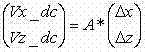
并且在Δx=0的情况下由Δz计算,在Δz=0的情况下由Δx计算。And it is calculated from Δz in the case of Δx=0, and calculated from Δx in the case of Δz=0.
该矩阵的逆the inverse of the matrix
将测量的电压变换成Δx和Δz数据的表格。这些计算的值与给定Δx和Δz之间的差值为误差并且示于表2中,表2示出了利用测量线圈获得的位置测量的精度。该表表明对于高达1.4mm的移位的精度小于18微米。这些误差以矢量形式显示并且单位为μm。Transform the measured voltages into a table of Δx and Δz data. The difference between these calculated values and the given Δx and Δz is the error and is shown in Table 2, which shows the accuracy of the position measurements obtained with the measuring coils. The table shows an accuracy of less than 18 microns for displacements up to 1.4mm. These errors are in vector form Displayed and the unit is μm.
表IITable II

在前面的实例中,像大多数针状扫描仪中的情况一样,存在金属(RVS)圆筒。然而,在一些情况下,针的外壳(例如MRI应用)必须是非金属的。为了研究金属圆筒的影响,做出比较。在图6中,针对Vx_dc示出了具有和没有RVS圆筒的情况下的结果。具有圆筒的情况下的信号更高且更对称,因而具有圆筒是更优选的解决方案。In the previous instance, as is the case in most needle scanners, there is a metal (RVS) cylinder. However, in some cases the housing of the needle (eg MRI applications) must be non-metallic. To study the effect of the metal cylinder, a comparison is made. In Fig. 6, the results with and without the RVS cylinder are shown for Vx_dc. With a cylinder the signal is higher and more symmetrical, so having a cylinder is a more preferred solution.
x线圈中的电流=26mA eff,频率=145kHzCurrent in x coil = 26mA eff, frequency = 145kHz
x、z线圈每线圈的N=160匝,测量线圈的N=250匝,N=160 turns of each coil of the x and z coils, N=250 turns of the measuring coil,
x线圈两端的电压=7.9VpThe voltage across the x coil = 7.9Vp
145kHz处放大带通滤波器=8.3Amplified bandpass filter = 8.3 at 145kHz
乘法器:v1*v2/10Multiplier: v1*v2/10
电子带通滤波器+乘法器+低通滤波器的传递:测量线圈上的125mVp给出334mVdcElectronic bandpass filter + multiplier + lowpass filter pass: 125mVp on measuring coil gives 334mVdc
具有RVS圆筒的情况下的测量结果:Measurements with RVS cylinder:
相移=0phase shift=0
在Δx=2.2mm上ΔVdc=220mVΔVdc=220mV on Δx=2.2mm
在Δx=2.2mm上每Amp_eff-及每N^2的测量线圈上mVp的计算:Calculation of mVp on each Amp_eff- and each N^2 measuring coil on Δx=2.2mm:
220 / 334 * 125 / 160 / 250 / 0.026 = 79e-3 mVp/N^2/Aeff。220 / 334 * 125 / 160 / 250 / 0.026 = 79e-3 mVp/N^2/Aeff.
1倍缩放比例: 1x scaling :
当所有的维度随着因素α变化时,测量线圈的电压预期也随着α变化。As all dimensions vary with factor α, the voltage of the measuring coil is expected to vary with α.
具有RVS圆筒的情况下10倍缩放比例和1倍缩放比例模型测量结果的比较如下:A comparison of the 10x scale and 1x scale model measurements with the RVS cylinder is as follows:
x线圈中的电流=77mA eff,频率=145kHzCurrent in x coil = 77mA eff, frequency = 145kHz
x、z线圈每线圈的N=90匝N=90 turns per coil of x and z coils
测量线圈的N=129匝N=129 turns of the measuring coil
测量结果:在Δx=0.22mm处测量线圈上的ΔVp=1.75mVpMeasurement results: Measure ΔVp=1.75mVp on the coil at Δx=0.22mm
这给出每N^2且每Amp_eff的mVp:1.75 / 129 / 90 / 0.077 = 2e-3:This gives mVp per N^2 and per Amp_eff: 1.75 / 129 / 90 / 0.077 = 2e-3:
为10倍缩放比例模型预期值=79e-3的1/4。For 10x scaling model expected value = 1/4 of 79e-3.
测量线圈的低输出使得区分希望的依赖于x、z的测量电压以及从线圈x和线圈z导线进入测量线圈导线的不希望的串扰更加困难。The low output of the measurement coils makes it more difficult to distinguish between the desired x, z dependent measurement voltage and the undesired crosstalk from the coil x and coil z wires into the measurement coil wires.
尽管比例定律看起来不成立,但是结果仍然表明对于较小的维度,本发明作为位置传感器是适用的。Although the laws of scaling do not appear to hold, the results still show that for smaller dimensions the invention is suitable as a position sensor.
图7示出了依照本发明的光学成像系统700,其包括所述光学探测器200(参见图2)、辐射源(R_S)701和成像检测器(I_D)702。辐射源(R_S)701光学耦合到光学探测器200,该光学探测器被设置用于将从辐射源发射的辐射引导到所述窗口240之外的感兴趣区域(参见图2)。成像检测器(I_D)702被设置用于使用来自样本(未示出)中感兴趣区域的反射的辐射成像。成像检测器(I_D)702也可以包括用户接口(UI),从而访问结果和/或控制成像过程。FIG. 7 shows an
在本发明的上下文中,应当理解的是,术语“辐射源”可以包括任何适当种类的辐射源,包括且不限于激光器(任何波长和任何操作模式,即连续的或者任何周期的脉冲式模式,包括飞秒激光器)、LED、气体放电灯、任何种类的发光等等。In the context of the present invention, it should be understood that the term "radiation source" may include any suitable kind of radiation source, including but not limited to lasers (any wavelength and any mode of operation, i.e. continuous or any periodic pulsed mode, Including femtosecond lasers), LEDs, gas discharge lamps, lighting of any kind, etc.
图8示出了依照本发明的用于光学成像的方法的流程图。Fig. 8 shows a flowchart of a method for optical imaging according to the present invention.
在第一步骤(S1)801中,提供所述光学探测器,并且提供辐射源(S2)802,该辐射源光学耦合到光学探测器。如前面在图2中所讨论的,探测器被设置用于将从辐射源发射的辐射引导到感兴趣区域。在第三步骤(S3)803中,利用光学耦合到光学探测器的成像检测器执行成像过程,该检测器被设置用于使用来自感兴趣区域的反射的辐射成像。In a first step (S1) 801, said optical detector is provided and a radiation source (S2) 802 is provided, which is optically coupled to the optical detector. As previously discussed in Figure 2, the detector is arranged to direct radiation emitted from the radiation source to the region of interest. In a third step (S3) 803, an imaging process is performed using an imaging detector optically coupled to an optical detector, the detector being arranged for imaging using reflected radiation from the region of interest.
关于进一步的细节,参见图2和图3的讨论。See the discussion of FIGS. 2 and 3 for further details.
出于解释而不是限制的目的,阐述了所公开实施例的一些特定的细节,以便提供对于本发明的清晰而透彻的理解。然而,本领域技术人员应当理解的是,在不明显脱离本公开内容的精神和范围的情况下,可以在不完全符合本文阐述的细节的其他实施例中实施本发明。此外,在本文中,出于简洁和清楚的目的,省略了对于公知设备、电路和方法的详细描述以便避免不必要的细节和可能的混淆。For purposes of explanation and not limitation, some specific details of the disclosed embodiments are set forth in order to provide a clear and thorough understanding of the present invention. However, it will be appreciated by those skilled in the art that the present invention may be practiced in other embodiments that do not conform exactly to the details set forth herein without departing significantly from the spirit and scope of the present disclosure. Furthermore, for the purposes of brevity and clarity herein, detailed descriptions of well-known devices, circuits and methods are omitted so as to avoid unnecessary detail and possible confusion.
权利要求中包含了附图标记,然而附图标记的包含仅仅出于清楚的原因并且不应当被视为限制了权利要求的范围。Reference signs are included in the claims, however their inclusion is for clarity reasons only and shall not be construed as limiting the scope of the claims.
Claims (15)
Applications Claiming Priority (3)
| Application Number | Priority Date | Filing Date | Title |
|---|---|---|---|
| EP08167689 | 2008-10-28 | ||
| EP08167689.2 | 2008-10-28 | ||
| PCT/IB2009/054644 WO2010049854A1 (en) | 2008-10-28 | 2009-10-21 | An optical probe having a position measuring system |
Publications (2)
| Publication Number | Publication Date |
|---|---|
| CN102196762A true CN102196762A (en) | 2011-09-21 |
| CN102196762B CN102196762B (en) | 2014-10-15 |
Family
ID=41508077
Family Applications (1)
| Application Number | Title | Priority Date | Filing Date |
|---|---|---|---|
| CN200980143023.5A Active CN102196762B (en) | 2008-10-28 | 2009-10-21 | An optical probe having a position measuring system |
Country Status (5)
| Country | Link |
|---|---|
| US (1) | US8977343B2 (en) |
| EP (1) | EP2341813B1 (en) |
| JP (1) | JP5587893B2 (en) |
| CN (1) | CN102196762B (en) |
| WO (1) | WO2010049854A1 (en) |
Cited By (1)
| Publication number | Priority date | Publication date | Assignee | Title |
|---|---|---|---|---|
| CN104105465A (en) * | 2012-04-12 | 2014-10-15 | 株式会社利卫多公司 | Absorbent article |
Families Citing this family (6)
| Publication number | Priority date | Publication date | Assignee | Title |
|---|---|---|---|---|
| RU2544457C2 (en) * | 2009-05-15 | 2015-03-20 | Конинклейке Филипс Электроникс Н.В. | Feedback corrected optical probe |
| US9452276B2 (en) | 2011-10-14 | 2016-09-27 | Intuitive Surgical Operations, Inc. | Catheter with removable vision probe |
| US9387048B2 (en) | 2011-10-14 | 2016-07-12 | Intuitive Surgical Operations, Inc. | Catheter sensor systems |
| US10238837B2 (en) | 2011-10-14 | 2019-03-26 | Intuitive Surgical Operations, Inc. | Catheters with control modes for interchangeable probes |
| US20130303944A1 (en) | 2012-05-14 | 2013-11-14 | Intuitive Surgical Operations, Inc. | Off-axis electromagnetic sensor |
| US10744320B2 (en) * | 2012-04-27 | 2020-08-18 | Medtronic, Inc. | Magnetic field detector for implantable medical devices |
Citations (5)
| Publication number | Priority date | Publication date | Assignee | Title |
|---|---|---|---|---|
| US20030183761A1 (en) * | 2002-03-29 | 2003-10-02 | Xerox Corporation | Scanning probe system with spring probe and actuation/sensing structure |
| US20030206321A1 (en) * | 1998-03-06 | 2003-11-06 | Gelikonov Valentin M. | Optical coherence tomography apparatus, optical fiber lateral scanner and a method for studying biological tissues in vivo |
| US20060013528A1 (en) * | 2002-10-30 | 2006-01-19 | Rosman Gavan E | Scanning method and apparatus |
| EP1901107A1 (en) * | 2006-09-14 | 2008-03-19 | Optiscan Pty Ltd | Optical fibre scanning apparatus |
| US20080101677A1 (en) * | 2006-10-27 | 2008-05-01 | Siemens Aktiengesellschaft | Apparatus for generating sectional images of tissue |
Family Cites Families (15)
| Publication number | Priority date | Publication date | Assignee | Title |
|---|---|---|---|---|
| JP3285924B2 (en) * | 1992-04-10 | 2002-05-27 | オリンパス光学工業株式会社 | Bay bending equipment |
| JPH06261858A (en) * | 1993-03-15 | 1994-09-20 | Olympus Optical Co Ltd | Shape measuring probe device |
| US5918274A (en) * | 1997-06-02 | 1999-06-29 | International Business Machines Corporation | Detecting fields with a single-pass, dual-amplitude-mode scanning force microscope |
| US6911026B1 (en) * | 1999-07-12 | 2005-06-28 | Stereotaxis, Inc. | Magnetically guided atherectomy |
| US6975898B2 (en) * | 2000-06-19 | 2005-12-13 | University Of Washington | Medical imaging, diagnosis, and therapy using a scanning single optical fiber system |
| US7555333B2 (en) * | 2000-06-19 | 2009-06-30 | University Of Washington | Integrated optical scanning image acquisition and display |
| JP2002000556A (en) * | 2000-06-26 | 2002-01-08 | Nonomura Tomosuke | Endoscope |
| US6845190B1 (en) | 2000-11-27 | 2005-01-18 | University Of Washington | Control of an optical fiber scanner |
| KR100794976B1 (en) * | 2000-11-30 | 2008-01-16 | 아실럼 리서치 코포레이션 | Enhanced linear variable differential transducer for high precision position measurement |
| US6669909B2 (en) * | 2001-03-26 | 2003-12-30 | Allegro Technologies Limited | Liquid droplet dispensing |
| US7248914B2 (en) * | 2002-06-28 | 2007-07-24 | Stereotaxis, Inc. | Method of navigating medical devices in the presence of radiopaque material |
| JP4914735B2 (en) * | 2007-02-14 | 2012-04-11 | オリンパスメディカルシステムズ株式会社 | Endoscope system for controlling the position of the treatment tool |
| JP2008246078A (en) * | 2007-03-30 | 2008-10-16 | Hoya Corp | Endoscope processor, and endoscopic system |
| US7608842B2 (en) * | 2007-04-26 | 2009-10-27 | University Of Washington | Driving scanning fiber devices with variable frequency drive signals |
| US8212884B2 (en) * | 2007-05-22 | 2012-07-03 | University Of Washington | Scanning beam device having different image acquisition modes |
-
2009
- 2009-10-21 WO PCT/IB2009/054644 patent/WO2010049854A1/en not_active Ceased
- 2009-10-21 CN CN200980143023.5A patent/CN102196762B/en active Active
- 2009-10-21 JP JP2011532756A patent/JP5587893B2/en not_active Expired - Fee Related
- 2009-10-21 US US13/125,812 patent/US8977343B2/en active Active
- 2009-10-21 EP EP09744471.5A patent/EP2341813B1/en active Active
Patent Citations (6)
| Publication number | Priority date | Publication date | Assignee | Title |
|---|---|---|---|---|
| US20030206321A1 (en) * | 1998-03-06 | 2003-11-06 | Gelikonov Valentin M. | Optical coherence tomography apparatus, optical fiber lateral scanner and a method for studying biological tissues in vivo |
| US20030183761A1 (en) * | 2002-03-29 | 2003-10-02 | Xerox Corporation | Scanning probe system with spring probe and actuation/sensing structure |
| US20060013528A1 (en) * | 2002-10-30 | 2006-01-19 | Rosman Gavan E | Scanning method and apparatus |
| EP1901107A1 (en) * | 2006-09-14 | 2008-03-19 | Optiscan Pty Ltd | Optical fibre scanning apparatus |
| US20080101677A1 (en) * | 2006-10-27 | 2008-05-01 | Siemens Aktiengesellschaft | Apparatus for generating sectional images of tissue |
| DE102006050885A1 (en) * | 2006-10-27 | 2008-05-08 | Siemens Ag | Device for generating tissue section images |
Cited By (3)
| Publication number | Priority date | Publication date | Assignee | Title |
|---|---|---|---|---|
| CN104105465A (en) * | 2012-04-12 | 2014-10-15 | 株式会社利卫多公司 | Absorbent article |
| CN104105465B (en) * | 2012-04-12 | 2015-11-25 | 株式会社利卫多公司 | absorbent article |
| US10201461B2 (en) | 2012-04-12 | 2019-02-12 | Livedo Corporation | Pants-type absorbent article |
Also Published As
| Publication number | Publication date |
|---|---|
| US20110201922A1 (en) | 2011-08-18 |
| WO2010049854A1 (en) | 2010-05-06 |
| US8977343B2 (en) | 2015-03-10 |
| JP2012506721A (en) | 2012-03-22 |
| JP5587893B2 (en) | 2014-09-10 |
| CN102196762B (en) | 2014-10-15 |
| EP2341813B1 (en) | 2014-12-10 |
| EP2341813A1 (en) | 2011-07-13 |
Similar Documents
| Publication | Publication Date | Title |
|---|---|---|
| CN102196762B (en) | An optical probe having a position measuring system | |
| US9675252B2 (en) | Scanning optical systems | |
| EP3010389B1 (en) | Omni-directional viewing apparatus and method | |
| US11835707B2 (en) | Scanning optical imaging device | |
| US20180085095A1 (en) | Apparatus and Method of Image Registration | |
| CN101909512B (en) | An optical probe | |
| EP2877096B1 (en) | Accurate and rapid mapping of points from ultrasound images to tracking systems | |
| JP2011500162A (en) | System, apparatus, and method employing optical fiber shape tracking | |
| Wang et al. | A confocal endoscope for cellular imaging | |
| JP2000262461A (en) | Optical imaging device | |
| CN115969409A (en) | Fiber Optic Ultrasound Probe | |
| CN103767660A (en) | Endoscope | |
| CN105476592A (en) | A separate endoscope | |
| US8201997B1 (en) | Imaging temperature sensing system | |
| JP6389828B2 (en) | Optical device for use with a medical imaging device | |
| US20140286604A1 (en) | Endo-microscopic probe based on non-resonant scanning method using optical fiber | |
| CN103930816A (en) | Light Microscopy Probe for Scanning Microscopy of Associated Objects | |
| CN216622169U (en) | Skin tissue spectrum detection device based on fluorescence and Raman fusion technology | |
| CN111426671A (en) | Imaging system based on fluorescence analysis | |
| JP2519272B2 (en) | Endoscope magnetic detection device | |
| Deonarine | Design and Development of the Optic Fiber Pulling Facility for the Development of the Imaging Probe for the Mosquito Bite Needle Endoscope | |
| Li et al. | Forward-looking OCT Probe Using Single-fiber Scanning for Transbronchial Puncturing Cytodiagnosis | |
| JP2000187121A (en) | Optical waveguide and biological measuring device using the same | |
| JP2575401B2 (en) | Antenna device for NMR measurement | |
| Lucesoli et al. | Distance optical sensor for quantitative endoscopy |
Legal Events
| Date | Code | Title | Description |
|---|---|---|---|
| C06 | Publication | ||
| PB01 | Publication | ||
| C10 | Entry into substantive examination | ||
| SE01 | Entry into force of request for substantive examination | ||
| C14 | Grant of patent or utility model | ||
| GR01 | Patent grant |