CN102177448A - Light beam direction control device and light output device - Google Patents
Light beam direction control device and light output device Download PDFInfo
- Publication number
- CN102177448A CN102177448A CN200980140175XA CN200980140175A CN102177448A CN 102177448 A CN102177448 A CN 102177448A CN 200980140175X A CN200980140175X A CN 200980140175XA CN 200980140175 A CN200980140175 A CN 200980140175A CN 102177448 A CN102177448 A CN 102177448A
- Authority
- CN
- China
- Prior art keywords
- optical element
- beam direction
- control device
- direction control
- optical
- Prior art date
- Legal status (The legal status is an assumption and is not a legal conclusion. Google has not performed a legal analysis and makes no representation as to the accuracy of the status listed.)
- Pending
Links
Images


Classifications
-
- G—PHYSICS
- G02—OPTICS
- G02B—OPTICAL ELEMENTS, SYSTEMS OR APPARATUS
- G02B3/00—Simple or compound lenses
- G02B3/0006—Arrays
- G02B3/0037—Arrays characterized by the distribution or form of lenses
- G02B3/0062—Stacked lens arrays, i.e. refractive surfaces arranged in at least two planes, without structurally separate optical elements in-between
-
- F—MECHANICAL ENGINEERING; LIGHTING; HEATING; WEAPONS; BLASTING
- F21—LIGHTING
- F21V—FUNCTIONAL FEATURES OR DETAILS OF LIGHTING DEVICES OR SYSTEMS THEREOF; STRUCTURAL COMBINATIONS OF LIGHTING DEVICES WITH OTHER ARTICLES, NOT OTHERWISE PROVIDED FOR
- F21V14/00—Controlling the distribution of the light emitted by adjustment of elements
- F21V14/04—Controlling the distribution of the light emitted by adjustment of elements by movement of reflectors
-
- F—MECHANICAL ENGINEERING; LIGHTING; HEATING; WEAPONS; BLASTING
- F21—LIGHTING
- F21V—FUNCTIONAL FEATURES OR DETAILS OF LIGHTING DEVICES OR SYSTEMS THEREOF; STRUCTURAL COMBINATIONS OF LIGHTING DEVICES WITH OTHER ARTICLES, NOT OTHERWISE PROVIDED FOR
- F21V14/00—Controlling the distribution of the light emitted by adjustment of elements
- F21V14/06—Controlling the distribution of the light emitted by adjustment of elements by movement of refractors
-
- F—MECHANICAL ENGINEERING; LIGHTING; HEATING; WEAPONS; BLASTING
- F21—LIGHTING
- F21V—FUNCTIONAL FEATURES OR DETAILS OF LIGHTING DEVICES OR SYSTEMS THEREOF; STRUCTURAL COMBINATIONS OF LIGHTING DEVICES WITH OTHER ARTICLES, NOT OTHERWISE PROVIDED FOR
- F21V5/00—Refractors for light sources
- F21V5/002—Refractors for light sources using microoptical elements for redirecting or diffusing light
- F21V5/004—Refractors for light sources using microoptical elements for redirecting or diffusing light using microlenses
-
- F—MECHANICAL ENGINEERING; LIGHTING; HEATING; WEAPONS; BLASTING
- F21—LIGHTING
- F21V—FUNCTIONAL FEATURES OR DETAILS OF LIGHTING DEVICES OR SYSTEMS THEREOF; STRUCTURAL COMBINATIONS OF LIGHTING DEVICES WITH OTHER ARTICLES, NOT OTHERWISE PROVIDED FOR
- F21V5/00—Refractors for light sources
- F21V5/002—Refractors for light sources using microoptical elements for redirecting or diffusing light
- F21V5/005—Refractors for light sources using microoptical elements for redirecting or diffusing light using microprisms
-
- F—MECHANICAL ENGINEERING; LIGHTING; HEATING; WEAPONS; BLASTING
- F21—LIGHTING
- F21V—FUNCTIONAL FEATURES OR DETAILS OF LIGHTING DEVICES OR SYSTEMS THEREOF; STRUCTURAL COMBINATIONS OF LIGHTING DEVICES WITH OTHER ARTICLES, NOT OTHERWISE PROVIDED FOR
- F21V5/00—Refractors for light sources
- F21V5/007—Array of lenses or refractors for a cluster of light sources, e.g. for arrangement of multiple light sources in one plane
-
- F—MECHANICAL ENGINEERING; LIGHTING; HEATING; WEAPONS; BLASTING
- F21—LIGHTING
- F21V—FUNCTIONAL FEATURES OR DETAILS OF LIGHTING DEVICES OR SYSTEMS THEREOF; STRUCTURAL COMBINATIONS OF LIGHTING DEVICES WITH OTHER ARTICLES, NOT OTHERWISE PROVIDED FOR
- F21V5/00—Refractors for light sources
- F21V5/008—Combination of two or more successive refractors along an optical axis
-
- F—MECHANICAL ENGINEERING; LIGHTING; HEATING; WEAPONS; BLASTING
- F21—LIGHTING
- F21V—FUNCTIONAL FEATURES OR DETAILS OF LIGHTING DEVICES OR SYSTEMS THEREOF; STRUCTURAL COMBINATIONS OF LIGHTING DEVICES WITH OTHER ARTICLES, NOT OTHERWISE PROVIDED FOR
- F21V5/00—Refractors for light sources
- F21V5/04—Refractors for light sources of lens shape
- F21V5/045—Refractors for light sources of lens shape the lens having discontinuous faces, e.g. Fresnel lenses
-
- G—PHYSICS
- G02—OPTICS
- G02B—OPTICAL ELEMENTS, SYSTEMS OR APPARATUS
- G02B19/00—Condensers, e.g. light collectors or similar non-imaging optics
- G02B19/0004—Condensers, e.g. light collectors or similar non-imaging optics characterised by the optical means employed
- G02B19/0009—Condensers, e.g. light collectors or similar non-imaging optics characterised by the optical means employed having refractive surfaces only
- G02B19/0014—Condensers, e.g. light collectors or similar non-imaging optics characterised by the optical means employed having refractive surfaces only at least one surface having optical power
-
- G—PHYSICS
- G02—OPTICS
- G02B—OPTICAL ELEMENTS, SYSTEMS OR APPARATUS
- G02B19/00—Condensers, e.g. light collectors or similar non-imaging optics
- G02B19/0033—Condensers, e.g. light collectors or similar non-imaging optics characterised by the use
-
- G—PHYSICS
- G02—OPTICS
- G02B—OPTICAL ELEMENTS, SYSTEMS OR APPARATUS
- G02B26/00—Optical devices or arrangements for the control of light using movable or deformable optical elements
- G02B26/08—Optical devices or arrangements for the control of light using movable or deformable optical elements for controlling the direction of light
- G02B26/0875—Optical devices or arrangements for the control of light using movable or deformable optical elements for controlling the direction of light by means of one or more refracting elements
- G02B26/0883—Optical devices or arrangements for the control of light using movable or deformable optical elements for controlling the direction of light by means of one or more refracting elements the refracting element being a prism
-
- G—PHYSICS
- G02—OPTICS
- G02B—OPTICAL ELEMENTS, SYSTEMS OR APPARATUS
- G02B3/00—Simple or compound lenses
- G02B3/0006—Arrays
- G02B3/0037—Arrays characterized by the distribution or form of lenses
- G02B3/005—Arrays characterized by the distribution or form of lenses arranged along a single direction only, e.g. lenticular sheets
-
- G—PHYSICS
- G02—OPTICS
- G02B—OPTICAL ELEMENTS, SYSTEMS OR APPARATUS
- G02B3/00—Simple or compound lenses
- G02B3/0006—Arrays
- G02B3/0037—Arrays characterized by the distribution or form of lenses
- G02B3/0056—Arrays characterized by the distribution or form of lenses arranged along two different directions in a plane, e.g. honeycomb arrangement of lenses
-
- G—PHYSICS
- G02—OPTICS
- G02B—OPTICAL ELEMENTS, SYSTEMS OR APPARATUS
- G02B5/00—Optical elements other than lenses
- G02B5/04—Prisms
- G02B5/045—Prism arrays
-
- F—MECHANICAL ENGINEERING; LIGHTING; HEATING; WEAPONS; BLASTING
- F21—LIGHTING
- F21S—NON-PORTABLE LIGHTING DEVICES; SYSTEMS THEREOF; VEHICLE LIGHTING DEVICES SPECIALLY ADAPTED FOR VEHICLE EXTERIORS
- F21S8/00—Lighting devices intended for fixed installation
- F21S8/04—Lighting devices intended for fixed installation intended only for mounting on a ceiling or the like overhead structures
-
- G—PHYSICS
- G02—OPTICS
- G02B—OPTICAL ELEMENTS, SYSTEMS OR APPARATUS
- G02B26/00—Optical devices or arrangements for the control of light using movable or deformable optical elements
- G02B26/08—Optical devices or arrangements for the control of light using movable or deformable optical elements for controlling the direction of light
- G02B26/10—Scanning systems
- G02B26/108—Scanning systems having one or more prisms as scanning elements
Landscapes
- Physics & Mathematics (AREA)
- General Physics & Mathematics (AREA)
- Optics & Photonics (AREA)
- Engineering & Computer Science (AREA)
- General Engineering & Computer Science (AREA)
- Non-Portable Lighting Devices Or Systems Thereof (AREA)
- Optical Elements Other Than Lenses (AREA)
- Mechanical Optical Scanning Systems (AREA)
Abstract
Description
技术领域technical field
本发明涉及光束方向控制装置,而且涉及包含这样的光束方向控制装置的光输出装置。The present invention relates to a beam direction control device, and to a light output device comprising such a beam direction control device.
背景技术Background technique
下照灯及聚光灯为建筑师、室内设计师以及最终用户所广泛使用,以用于创造期望的室内风格。Downlights and spotlights are widely used by architects, interior designers, and end users to create a desired interior style.
下照灯主要用于通用照明目的且通常产生相对宽的光束,而聚光灯通常通过对聚光灯进行倾斜及旋转而瞄准特定目标。Downlights are mainly used for general lighting purposes and usually produce a relatively wide beam, while spotlights are usually aimed at a specific target by tilting and swiveling the spotlight.
近来,照明技术的进步,尤其是发光二极管(LED)以及基于LED的发光体领域的进步,已经允许扁平且紧凑的诸如灯具的光输出装置,与传统照明系统相比,这样的光输出装置容易安装且更加紧凑及不突兀。Recent advances in lighting technology, especially in the field of light-emitting diodes (LEDs) and LED-based illuminants, have allowed for flat and compact light output devices such as lamps, which are easier to produce than conventional lighting systems. Installation is more compact and unobtrusive.
对于下照灯,使用这种新型扁平发光体相对直接。然而,对于聚光灯,目前优势还不明显,因为控制光方向所需要的机械布置自身相对庞大,且因此抵消了使用扁平发光体所能获得的较小规格。For downlights, using this new flat illuminant is relatively straightforward. For spotlights, however, the advantage is not so far evident, since the mechanical arrangement required to control the direction of the light is itself relatively bulky, and thus offsets the smaller dimensions that can be obtained with flat illuminants.
发明内容Contents of the invention
鉴于现有技术的上述缺陷以及其它缺陷,本发明的总体目的是提供一种改善的光束方向控制装置,且具体地提供一种紧凑光束方向装置,其允许简单且可靠地控制穿过所述紧凑光束方向装置的光束的方向。In view of the above and other disadvantages of the prior art, it is a general object of the present invention to provide an improved beam direction control device, and in particular a compact beam direction device which allows simple and reliable control of beams passing through said compact beam direction device. Beam Direction The direction of the beam of the device.
根据第一方面,本发明提供了光束方向控制装置,其用于控制由光源发射且穿过所述光束方向控制装置的光束的方向,所述装置包含:具有第一及第二相对面的第一光学元件,其被配置为将在第一光学元件的第一面以入射方向入射到光束方向控制装置的多个平行光线的方向改变为在第一光学元件的第二面的与入射方向不同的初级方向;以及具有第一及第二相对面的第二光学元件,其被布置为第二光学元件的第一面面对第一光学元件的第二面,第二光学元件被配置为依赖于光线在第二光学元件的第一面的入射点而将多个光线的方向从在第二光学元件的第一面的初级方向改变为在第二光学元件的第二面的次级方向,其中光束方向控制装置被配置为允许第一和第二光学元件之间的相对移动以控制光线在第二光学元件的第一面上的入射点,由此允许控制光束的方向。According to a first aspect, the present invention provides a beam direction control device for controlling the direction of a light beam emitted by a light source and passing through said beam direction control device, said device comprising: a first beam having first and second opposing surfaces An optical element, which is configured to change the direction of a plurality of parallel light rays incident on the beam direction control device in the direction of incidence on the first surface of the first optical element to be different from the direction of incidence on the second surface of the first optical element and a second optical element having first and second opposing faces arranged such that the first face of the second optical element faces the second face of the first optical element, the second optical element being configured to depend on changing the direction of a plurality of light rays from a primary direction on the first face of the second optical element to a secondary direction on the second face of the second optical element at the point of incidence of the light rays on the first face of the second optical element, Wherein the beam direction control means is configured to allow relative movement between the first and second optical elements to control the point of incidence of light on the first face of the second optical element, thereby allowing control of the direction of the light beam.
光束方向控制装置可能有利地包含用于允许第一和第二光学元件之间的上述提到的相对移动的移动装置。The beam direction control means may advantageously comprise movement means for allowing the above mentioned relative movement between the first and second optical elements.
这里使用的“移动装置”应当被理解为意指任何能够提供第一和第二光学元件之间期望的相对移动的装置。这样的移动装置可能包含可能以一个或多个操纵杆、手柄等的形式提供的人工操作装置。移动装置可能另外包含装有动力的致动器。例如电机、气动或者液压致动器等。"Moving means" as used herein should be understood to mean any means capable of providing the desired relative movement between the first and second optical elements. Such mobile devices may include manually operated means, possibly in the form of one or more joysticks, handles or the like. The mobile device may additionally contain powered actuators. Such as electric motors, pneumatic or hydraulic actuators, etc.
第一及第二光学元件可能是具有所宣称特性的任何光学元件。有利地,第一及第二光学元件中的每一个均可能以光学上透明的平面元件形式提供,例如平板或者箔。The first and second optical elements may be any optical elements having the claimed properties. Advantageously, each of the first and second optical elements may be provided in the form of an optically transparent planar element, such as a plate or a foil.
本发明基于以下认识:可通过提供两个串联的光学元件来获得用于控制光束方向的非常紧凑的装置,其中第一光学元件偏转光线使得其以给定的方向在给定的一组入射点上射到第二光学元件上,且第二光学元件被配置为依赖于入射点而不同地偏转这些光线。The invention is based on the realization that a very compact device for controlling the direction of a beam of light can be obtained by providing two optical elements connected in series, where the first optical element deflects the light so that it falls at a given set of incident points in a given direction are incident on the second optical element, and the second optical element is configured to deflect the rays differently depending on the point of incidence.
发明人进一步认识到,通过相对于第一光学元件移动第二光学元件而获得新的一组入射点和/或以光学元件之间恒定的相互位置关系移动第一及第二光学元件以在保持入射点不改变的情况下改变射到第二光学元件的光线的方向,这样的装置能够实际地用于在给定范围内连续地控制光束的方向。The inventors have further realized that by moving the second optical element relative to the first optical element to obtain a new set of incident points and/or moving the first and second optical elements in a constant mutual positional relationship between the optical elements to maintain Such a device that changes the direction of the light beam impinging on the second optical element without changing the point of incidence can be practically used to continuously control the direction of the light beam within a given range.
相应地,只需要在垂直于光束方向控制装置的光轴的方向上的移动,这允许形成尤其适用于与扁平且紧凑的基于半导体光源的光输出装置(例如基于LED的扁平下照灯)相结合使用的非常紧凑的光束方向控制装置。通过将这样的扁平下照灯与根据本发明实施方式的光束方向控制装置相结合,可在几乎不牺牲下照灯的紧凑性以及不突兀性中的任何一个的情况下将下照灯转化为可控制的聚光灯。Accordingly, only a movement in a direction perpendicular to the optical axis of the beam direction control device is required, which allows the formation of a light output device especially suitable for use with flat and compact semiconductor light source-based light output devices, such as LED-based flat downlights. Combined with a very compact beam direction control device. By combining such a flat downlight with a beam direction control device according to an embodiment of the present invention, it is possible to convert the downlight into a Controllable spotlights.
第一及第二光学元件可能有利地被布置为基本相互平行,依赖于实际实施方式这能够改善性能和/或便利光束方向控制装置的生产和组装。对于根据本发明的光束方向控制装置的至少一些实施方式,期望当第一及第二光学元件被布置在从被布置在平行平面中偏离大约±10°以内时获得最佳性能。The first and second optical elements may advantageously be arranged substantially parallel to each other, which, depending on the actual implementation, can improve performance and/or facilitate production and assembly of the beam direction control device. For at least some embodiments of beam direction control devices according to the present invention, it is expected that optimum performance will be obtained when the first and second optical elements are arranged within about ±10° from being arranged in parallel planes.
为限制由包含光源及根据本发明实施方式的光束方向控制装置的光输出装置发射的光的不需要的变宽或者变窄,移动装置可能有利地被配置为允许在保持第一和第二光学元件之间的距离恒定的情况下,第一和第二光学元件之间的相对移动。In order to limit undesired broadening or narrowing of the light emitted by the light output means comprising the light source and beam direction control means according to embodiments of the invention, the moving means may advantageously be configured to allow the first and second optical Relative movement between the first and second optical elements with a constant distance between the elements.
另外,第一和第二光学元件中的每一个可能包含重定向结构阵列,借此,能够保持获得光束方向一定改变所要求的相对运动较小,这允许提供非常紧凑的光束方向控制装置,且因而允许提供紧凑且不突兀的可控制聚光灯。In addition, each of the first and second optical elements may comprise an array of redirecting structures, whereby the relative movement required to obtain a certain change in beam direction can be kept small, which allows very compact beam direction control means to be provided, and Thus allowing to provide a compact and unobtrusive controllable spotlight.
一般而言,包含在根据本发明的光束方向控制装置中的光学元件可能使用任何机制以获得光线的期望的重定向。这样的机制可能包含,举例来说,反射、电或者磁控制的折射、通过全内反射的光引导或者这些机制与其他机制的任何组合。然而,通过由折射结构阵列提供期望的重定向,便利了光束方向控制装置的制造,且能够使用现有的相对低成本的光学元件。In general, the optical elements included in the beam direction control device according to the invention may use any mechanism to obtain the desired redirection of the light rays. Such mechanisms may include, for example, reflection, electrically or magnetically controlled refraction, light guidance by total internal reflection, or any combination of these mechanisms with others. However, by providing the desired redirection by the array of refractive structures, the manufacture of the beam direction control device is facilitated and enables the use of existing relatively low cost optical elements.
根据一个实施方式,第一和第二光学元件中的每一个可能包含棱镜板,且光束方向控制装置可能被配置为允许在第一和第二光学元件之间关于光束方向控制装置的光轴的相对旋转。According to one embodiment, each of the first and second optical elements may comprise a prism plate, and the beam direction control device may be configured to allow movement between the first and second optical elements with respect to the optical axis of the beam direction control device relative rotation.
在这个实施方式中,分别包含在第一及第二光学元件中的第一及第二棱镜板中的每一个能够以固定的给定极偏转角(即相对于光束方向控制装置的光轴的固定的给定角度)偏转入射平行光线。然而,被偏转的光线因而产生的方向也依赖于被偏转光线的方位角,其反过来依赖于关于各自棱镜板的光轴的旋转。In this embodiment, each of the first and second prism plates included in the first and second optical elements respectively can be deflected at a fixed given polar deflection angle (i.e. relative to the optical axis of the beam direction control device). A fixed given angle) deflects incident parallel rays. However, the resulting direction of the deflected light rays also depends on the azimuth angle of the deflected light rays, which in turn depends on the rotation about the optical axis of the respective prism plate.
因此,光束从根据本实施方式的光束方向控制装置出射的方向,即光束的极角以及方位角,可通过控制第一和第二光学元件的旋转来控制。Therefore, the direction of the beam emitted from the beam direction control device according to this embodiment, ie, the polar angle and the azimuth angle of the beam, can be controlled by controlling the rotation of the first and second optical elements.
为方便用户,可能给光束方向控制装置提供移动装置,所述移动装置包含用于允许用户控制第一和第二棱镜板之间的相对旋转(相对方位角)的第一用户可控制致动器,以及用于允许用户控制第一和第二棱镜板之间的共同旋转(相对方位角恒定)的第二用户可控制致动器。For user convenience, it is possible to provide the beam direction control means with movement means comprising a first user controllable actuator for allowing the user to control the relative rotation (relative azimuth) between the first and second prism plates , and a second user controllable actuator for allowing user control of the common rotation (relative azimuth constant) between the first and second prism plates.
此外,第一及第二光学元件中的每一个的第一面可能基本为平面,且所述第一及第二光学元件中的每一个的第二面可能具有形成于其上的棱镜结构。Additionally, the first face of each of the first and second optical elements may be substantially planar, and the second face of each of the first and second optical elements may have prismatic structures formed thereon.
通过以这样的方式布置光学元件,使得入射光线首先射到其平坦一侧,则在不同于计划方向的另一方向上的伴随光束的形成由于在光学元件/棱镜板中的全内反射而大大降低了。By arranging the optical element in such a way that the incident ray strikes its flat side first, the formation of accompanying beams in another direction than the intended direction is greatly reduced due to total internal reflection in the optical element/prism plate up.
应当注意,两个棱镜板或者箔不需要相同。举例来说,针对包含在第二光学元件中的棱镜板或者箔使用稍微较小的棱镜角以减轻偏转伪影可能是有利的。It should be noted that the two prism sheets or foils need not be identical. For example, it may be advantageous to use somewhat smaller prism angles for prism plates or foils included in the second optical element to mitigate deflection artifacts.
此外,通过在第一及第二光学元件上提供减反射层覆盖层能够抑制菲涅尔反射引起的杂散光。替代地或者组合地,为相同的目的,可在两个棱镜板/箔之间放置百叶箔(louvre foil)。百叶箔的透射定向可能有利地与棱镜板/箔之间的被偏转的光束方向重合,即百叶箔可能有利地依附在第一光学元件上。In addition, stray light caused by Fresnel reflection can be suppressed by providing an anti-reflection coating layer on the first and second optical elements. Alternatively or in combination, a louver foil can be placed between two prism plates/foils for the same purpose. The transmission orientation of the louver foil may advantageously coincide with the deflected beam direction between the prism plate/foil, ie the louver foil may advantageously be attached to the first optical element.
根据另一实施方式,第一光学元件可能包括第一透镜阵列,第一透镜阵列包含多个聚焦透镜;第二光学元件可能包括第二透镜阵列;以及光束方向控制装置可能被配置为允许第一及第二光学元件在垂直于光束方向控制装置的光轴的平面内相对横向位移。According to another embodiment, the first optical element may comprise a first lens array comprising a plurality of focusing lenses; the second optical element may comprise a second lens array; and the beam direction control means may be configured to allow the first and the second optical element is relatively laterally displaced in a plane perpendicular to the optical axis of the beam direction control device.
在这个实施方式中,光束由第一透镜阵列中的每个透镜聚焦,使得形成在初级方向上的多个平行光线,每个均与第一透镜阵列中的各自透镜相关联。然后这些光线由第二透镜阵列中的透镜偏转依赖于这些光线中的每一个在何处射到第二透镜阵列中的对应透镜的方向。In this embodiment, the light beam is focused by each lens in the first lens array such that a plurality of parallel rays in a primary direction are formed, each associated with a respective lens in the first lens array. These rays are then deflected by the lenses in the second lens array in a direction dependent on where each of these rays strikes a corresponding lens in the second lens array.
通过使用与第一透镜阵列具有基本相同间距(相邻透镜之间的距离)的第二透镜阵列,可提供允许通过以对应于间距的最大距离相对于第一光学元件横向移动第二光学元件来控制光束方向的光束方向控制装置。By using a second lens array having substantially the same pitch (distance between adjacent lenses) as the first lens array, it is possible to provide a lens that allows the second optical element to be viewed by moving the second optical element laterally relative to the first optical element by a maximum distance corresponding to the pitch. A beam direction control device for controlling the direction of the beam.
因此,为提供光束方向的平滑及连续的控制,移动装置可能有利地被配置为允许最大相对横向位移小于或者等于第一及第二透镜阵列的间距。Therefore, to provide smooth and continuous control of the beam direction, the movement means may advantageously be configured to allow a maximum relative lateral displacement less than or equal to the pitch of the first and second lens arrays.
另外,透镜阵列可能有利地各自具有20mm或者更小的间距以保持最大光束偏转所需要的机械移动适宜地小。Additionally, the lens arrays may advantageously each have a pitch of 20 mm or less to keep the mechanical movement required for maximum beam deflection suitably small.
移动装置可能额外地被配置为允许改变第一及第二光学元件之间的距离,借此,可以控制光束的发散。The movement means may additionally be configured to allow changing the distance between the first and second optical elements, whereby the divergence of the light beam can be controlled.
使用针对第二透镜阵列的各种配置来获得光束方向的期望的控制。Various configurations for the second lens array are used to obtain the desired control of the beam direction.
根据一个示例,第二透镜阵列可能(像第一透镜阵列一样)包含多个聚焦透镜。另外,第二透镜阵列中的透镜,有利地,比第一透镜阵列中的透镜更聚焦(“强”)。According to an example, the second lens array may (like the first lens array) contain a plurality of focusing lenses. In addition, the lenses in the second lens array are advantageously more focused ("stronger") than the lenses in the first lens array.
在根据本示例的光束方向控制装置中,模拟及实验给出第一透镜阵列中的透镜的焦距可能有利地在第一透镜阵列间距的2到10倍范围内。然后,第二透镜阵列中的透镜的焦距可能优选地在第一(第二)透镜阵列间距的0.5到1.5倍范围内。在此,可通过第二光学元件相对于第一光学元件相对小的横向位移而获得光束相对大的角位移。In the beam direction control device according to this example, simulations and experiments show that the focal lengths of the lenses in the first lens array may advantageously be in the range of 2 to 10 times the pitch of the first lens array. Then, the focal length of the lenses in the second lens array may preferably be in the range of 0.5 to 1.5 times the pitch of the first (second) lens array. Here, a relatively large angular displacement of the light beam can be achieved by a relatively small lateral displacement of the second optical element relative to the first optical element.
根据另一示例,第二透镜阵列中的每一个透镜可能包含被配置为提供以初级方向入射到第二光学元件的光线的全内反射的第一部分;及被配置为对光线进行折射的第二部分。According to another example, each lens in the second lens array may comprise a first portion configured to provide total internal reflection of light rays incident on the second optical element in a primary direction; and a second portion configured to refract the light rays. part.
据此,第二透镜阵列中的透镜可能做得非常强,借此,可获得较大的偏转角。Accordingly, the lenses in the second lens array may be made very strong, thereby obtaining a larger deflection angle.
根据另一示例,第二透镜阵列可能包含多个发散或者负透镜,借此,可获得与聚焦透镜基本相同的重定向效果。According to another example, the second lens array may comprise a plurality of diverging or negative lenses, whereby substantially the same redirection effect as that of focusing lenses can be obtained.
另外,光束方向控制装置可能另外包含布置在第一及第二光学元件之间的另一光学元件,另一光学元件具有与第一及第二光学元件的平均折射率不同的折射率,即小于0.3。In addition, the beam direction control device may additionally comprise another optical element arranged between the first and second optical elements, the other optical element having a different refractive index from the average refractive index of the first and second optical elements, i.e. less than 0.3.
据此,可获得更短的焦距,这允许更加紧凑的光束方向控制装置。另外,可改善透镜的光学质量。Hereby, a shorter focal length can be obtained, which allows a more compact beam direction control device. In addition, the optical quality of the lens can be improved.
提供这样的另一光学元件的附加有利效果是可降低杂散菲涅尔反射。An additional advantageous effect of providing such a further optical element is that stray Fresnel reflections can be reduced.
因为第一及第二光学元件的折射率大致为1.5左右,另一光学元件的折射率可能大多数情况下在1.2到1.8之间。Since the refractive index of the first and second optical elements is roughly around 1.5, the refractive index of the other optical element may be between 1.2 and 1.8 in most cases.
为易于制造和处理,另一光学元件可能优选地以液体或者胶体的形式提供。For ease of manufacture and handling, the further optical element may preferably be provided in liquid or gel form.
对于在其中第一及第二光学元件的每一个包含透镜阵列的本发明的实施方式,有利地,在第一和第二透镜阵列之间提供包含透镜阵列的另一,即第三光学元件。For embodiments of the invention in which each of the first and second optical elements comprises a lens array, it is advantageous to provide a further, ie third, optical element comprising a lens array between the first and second lens arrays.
通过合适地选择第三透镜阵列中的透镜的特性,可获得光束控制装置改善的光束控制性能。具体地,可获得较大的最大光束偏转角。By suitable selection of the characteristics of the lenses in the third lens array, improved beam steering performance of the beam steering device can be obtained. Specifically, a larger maximum beam deflection angle can be obtained.
可以优选地选择第三透镜阵列的透镜的焦距使得第三透镜阵列将第一透镜阵列映像在第二透镜阵列上。The focal lengths of the lenses of the third lens array may preferably be selected such that the third lens array maps the first lens array onto the second lens array.
另外,第三透镜阵列可以有利地放置在第一透镜阵列的焦平面中,其中第一透镜阵列的焦平面与第二透镜阵列的焦平面重合。In addition, the third lens array may advantageously be placed in the focal plane of the first lens array, wherein the focal plane of the first lens array coincides with the focal plane of the second lens array.
在各种实施方式中,移动装置可能另外被配置为相对于第一光学元件移动第三光学元件,借此,可获得更进一步的最大光束偏转角。In various embodiments, the moving means may additionally be configured to move the third optical element relative to the first optical element, whereby a further maximum beam deflection angle may be obtained.
为获得更大的偏转角,可堆叠一些更多元件,其中每个元件包含透镜阵列。举例来说,可在第一透镜阵列的焦平面中放置一额外透镜阵列,且可在第二透镜阵列的焦平面中放置另一额外透镜阵列。多个透镜阵列的堆叠的光学特性可能是有利地使得第一透镜阵列映像在第二透镜阵列上。另外,移动装置可能以这样的方式配置使得一些透镜阵列中的一个的横向位置相对于第一透镜阵列的横向位置可调整。For larger deflection angles, a few more elements can be stacked, where each element contains a lens array. For example, one additional lens array can be placed in the focal plane of the first lens array, and another additional lens array can be placed in the focal plane of the second lens array. The optical properties of the stack of multiple lens arrays may be advantageous such that the first lens array is imaged on the second lens array. Additionally, the mobile device may be configured in such a way that the lateral position of one of the lens arrays is adjustable relative to the lateral position of the first lens array.
另外,根据本发明的光束方向控制装置可能有利地包含在光输出装置中,所述光输出装置进一步包含被布置为发射穿过光束方向控制装置的光的光源。Furthermore, the beam direction controlling device according to the invention may advantageously be comprised in a light output device further comprising a light source arranged to emit light passing through the beam direction controlling device.
如上所提到的,这样的光输出装置可能有利地为可控制聚光灯。As mentioned above, such light output means may advantageously be a controllable spotlight.
附图说明Description of drawings
现在将参考示出本发明当前优选实施方式的所附的附图来详细描述本发明的这些方面及其他方面,在附图中:These and other aspects of the invention will now be described in detail with reference to the accompanying drawings showing presently preferred embodiments of the invention, in which:
图1a-b示出了现有技术照明方案;Figures 1a-b illustrate prior art lighting solutions;
图2示意性地示出了包含根据本发明一个实施方式的光束方向控制装置的光输出装置;Fig. 2 schematically shows a light output device comprising a beam direction control device according to an embodiment of the present invention;
图3a-c示意性地示出了根据本发明实施方式的在不同光束方向控制状态中的光束方向控制装置;Figures 3a-c schematically illustrate a beam direction control device in different beam direction control states according to an embodiment of the present invention;
图4a-b示意性地示出了根据本发明的在不同光束方向控制状态中的光束方向控制装置的第一实施方式;Figures 4a-b schematically illustrate a first embodiment of a beam direction control device according to the present invention in different beam direction control states;
图5a-d示意性地示出了使用图4a-b的光束方向控制装置获得的示例性光束方向控制状态;Figures 5a-d schematically illustrate exemplary beam direction control states obtained using the beam direction control device of Figures 4a-b;
图6a-b示意性地示出了根据本发明的在不同光束方向控制状态中的光束方向控制装置的第二实施方式;Figures 6a-b schematically illustrate a second embodiment of the beam direction control device according to the present invention in different beam direction control states;
图7a-c为图6a-c中的光束方向控制装装置的部分的截面图,其示意性地示例了光束方向控制装置的工作机制;7a-c are cross-sectional views of parts of the beam direction control device in FIGS. 6a-c, which schematically illustrate the working mechanism of the beam direction control device;
图8示意性地示出了图7a-b中的光束方向控制装置的各个参数之间的关系;Fig. 8 schematically shows the relationship between various parameters of the beam direction control device in Fig. 7a-b;
图9a-c为示例性地示出了在第二透镜阵列中使用替代类型的透镜的截面图;Figures 9a-c are cross-sectional views exemplarily illustrating the use of alternative types of lenses in the second lens array;
图10为示出了图6a-c中的光束方向控制装置的另一示例性配置的截面图;Figure 10 is a cross-sectional view showing another exemplary configuration of the beam direction control device in Figures 6a-c;
图11a-b示出了图6a-c中的光束方向控制装置的又一示例性配置;Figures 11a-b illustrate yet another exemplary configuration of the beam direction control device in Figures 6a-c;
图12a-c示意性地示出了各种替代透镜阵列配置;以及Figures 12a-c schematically illustrate various alternative lens array configurations; and
图13a-b示意性地示出了根据本发明的在不同光束方向控制状态中的光束方向控制装置的第三实施方式。Figures 13a-b schematically show a third embodiment of the beam direction control device according to the invention in different beam direction control states.
具体实施方式Detailed ways
图1a示意性地示出了扁平且紧凑的下照灯1,其安装在天花板2上以发射直接向下的光。这样的下照灯1可能基于,举例来说,诸如LED的半导体光源,以及用于调节(混合及分配)由光源发射的光的导光布置。Figure 1a schematically shows a flat and
另外,图1b示意性地示出了传统聚光灯3,其经由普通机械光束方向控制装置4安装在天花板2上。通过人工地倾斜及旋转聚光灯3,从其发射的光束5的方向可随意控制。Furthermore, FIG. 1 b schematically shows a
如果直接将图1a中的扁平且紧凑的下照灯1与图1b中的机械光束方向控制装置4相结合,则将得到基于图1a中的扁平下照灯1的聚光灯。然而,将会失去图1a中的下照灯1的许多使其对部署在各种照明方案中有吸引力的特征。If the flat and
为了在保持图1a中的下照灯1的许多有吸引力的特征的情况下提供用户可控制的聚光灯,如图2示意性所示,可使用根据本发明的光束方向控制装置的各种实施方式。In order to provide a user-controllable spotlight while maintaining many of the attractive features of the
在图2中,示出了可控制聚光灯20形式的光输出装置,其包含类似于图1a中的下照灯1的扁平且紧凑的发光装置21,及根据本发明一个实施方式的光束方向控制装置22,其被布置为使得当聚光灯20工作时,由发光装置21发射的光穿过光束方向控制装置。In Fig. 2, a light output device in the form of a
图2中的光束方向控制装置22包含第一23及第二24光学元件,通过使用第一25及第二26致动器形式的各自的移动装置,第一23及第二24光学元件中的每一个都可在平行于天花板2的平面中移动,通过所述移动装置,用户可相互独立地移动第一23及第二24光学元件。The beam
通过致动器25及26的操作,可控制由聚光灯20发射的光束28的方向。Through the operation of the
参考图3a-c,现在将描述根据本发明的光束方向控制装置的基本工作原理。Referring to Figures 3a-c, the basic working principle of the beam direction control device according to the invention will now be described.
在图3a中,示出了在第一光束方向控制状态中的光束方向控制装置30。另外,图3b以及图3c各自示出了用于将光束方向控制装置30带入其他光束方向控制状态的两个不同的基本原理。In Fig. 3a, the beam
首先转向图3a,光束方向控制装置30包含具有第一面32及第二面33的第一光学元件31,及具有第一面36及第二面37的第二光学元件35。第二光学元件35被布置在基本与第一光学元件31平行的平面内,且第二光学元件35的第一面36面对第一光学元件31的第二面33。Turning first to FIG. 3 a , the beam
如图3a示意性示出的,第一光学元件31被配置为将多个入射平行光线40的方向从在第一光学元件31的第一面32的入射方向ri改变为在第一光学元件31的第二面33的初级方向rp。As shown schematically in FIG. 3 a, the first
光线因而以初级方向rp在相应的多个入射点41(在图3a中标示为“x”)上射到第二光学元件35的第一面36上。The light rays thus impinge on the
依赖于入射点41,第二光学元件35被配置为将射到其第一面36的光线的方向由初级方向rp改变为次级方向rs1,其在图3a示出的光束方向控制状态中平行于光束方向控制装置30的光轴OA。Depending on the point of
依赖于第二光学元件35的配置,多个平行光线从初级方向到不同的次级方向rs2的重定向的所期望的变化可以通过第二光学元件35相对于第一光学元件31的旋转移动、线性移动、或者两者的结合来获得。Depending on the configuration of the second
参考图3b,将解释一示例性情况,在其中第二光学元件35被配置为通过第二光学元件35相对于第一光学元件31的旋转移动而获得重定向的期望的变化。With reference to Fig. 3b, an exemplary case will be explained in which the second
在图3b中,将第一光学元件31保持在与图3a中相同的位置。因而,以入射方向ri射到第一光学元件31的第一面32的入射光线40被重定向到与图3a中相同的初级方向rp。In Fig. 3b, the first
由于图3b中的第二光学元件35已经相对于第一光学元件31旋转,现在在初级方向rp上的光线在不同的一组入射点42(在图3b中标示为“o”)上射到第二光学元件35的第一面36上。图3b示出了第二光学元件35旋转前的入射点41,以示例说明与图3a的情形相比存在改变。Since the second
如在图3b中示例性示出的,入射点的改变导致次级方向从图3a的rs1到图3b的rs2的改变。相应地,通过相对第一光学元件31旋转第二光学元件35,光束方向控制装置30被置于第二光束方向控制状态中。As shown exemplarily in Fig. 3b, a change of the point of incidence results in a change of the secondary direction from rs 1 of Fig. 3a to rs 2 of Fig. 3b. Correspondingly, by rotating the second
以下参考图4a-b提供被配置为响应于相对于第一光学元件旋转第二光学元件而控制光束方向的光束方向控制装置的更详细描述。A more detailed description of a beam direction control device configured to control the direction of a beam of light in response to rotating the second optical element relative to the first optical element is provided below with reference to Figures 4a-b.
参考图3c,示出了不同的情况,在其中从初级方向rp到次级方向rs2的期望的重定向反而是通过相对于第一光学元件31横向地平移第二光学元件35获得的,如图3c中的箭头所标示的。Referring to Fig. 3c, a different situation is shown in which the desired redirection from the primary direction rp to the secondary direction rs2 is instead obtained by translating the second
以下参考图6a-b提供被配置为响应于相对于第一光学元件横向地平移第二光学元件而控制光束方向的光束方向控制装置的更详细描述。A more detailed description of a beam direction control device configured to control the direction of a beam of light in response to laterally translating the second optical element relative to the first optical element is provided below with reference to Figures 6a-b.
图4a-b示意性地示出了在不同光束方向控制状态中的根据本发明的光束方向控制装置的第一实施方式。Figures 4a-b schematically show a first embodiment of the beam direction control device according to the invention in different beam direction control states.
在图4a-b中,提供了包含在光束方向控制装置45中的棱镜板或者是棱镜箔形式的第一46及第二47光学元件,如附图示意性地标示的。In Figures 4a-b there is provided a first 46 and a second 47 optical element in the form of a prism plate or prism foil comprised in the beam direction controlling means 45, as schematically indicated in the figures.
这样的棱镜板或者棱镜箔目前使用在液晶显示器(LCD)中,以将LCD的图像输出以给定的、固定方向对着观看者的预期位置。Such prism sheets or prism foils are currently used in liquid crystal displays (LCDs) to orient the image output of the LCD in a given, fixed direction towards the intended position of the viewer.
通过以图4a-b标示的方式布置两个这样的棱镜板,通过合适地旋转第一46及第二47光学元件,光束的方位角和极角两者都可随意确定(在一定极角范围内)。By arranging two such prism plates in the manner indicated in Fig. 4a-b, by suitably rotating the first 46 and second 47 optical elements, both the azimuthal and polar angles of the light beam can be arbitrarily determined (within a certain polar angle range Inside).
在图4a及图4b两者中,第一光学元件46以这样的方式定向,使得入射光线40从原始方向ri重定向到初级方向,如图4a-b示意性示出的。具体地,从原始方向ri到初级方向rp的重定向是通过旋转第一光学元件46,使得在其第二面上的棱镜式结构48定向为将入射光线40折射到期望的方向而获得的。In both Fig. 4a and Fig. 4b, the first
在图4a中,第二光学元件47被反平行布置(第二光学元件47的棱镜式结构49相对于第一光学元件46的棱镜式结构48旋转了180°),使得与第一光学元件46相比,第二光学元件47以同样的幅度及相反的方向重定向入射到其上的光线。如图4a示意性示出的,得到的光束偏转为零,即次级方向rs与入射方向ri相同。In FIG. 4a, the second
通过相对于第一光学元件46旋转第二光学元件47,第一46及第二47光学元件的偏转的矢量和产生非零的光束偏转,即次级方向rs与入射方向ri不同。By rotating the second
这在图4b中示意性地示出,其中与图4a中所示的情况相比,第一光学元件46的棱镜式结构48与第二光学元件47的棱镜式结构49之间方位角的差减小了大约60°,即现在第二光学元件47的棱镜式结构49相对于第一光学元件46的棱镜式结构48旋转了大约120°。This is shown schematically in FIG. 4b, where the difference in azimuthal angle between the
图5a-d示例了通过在图4a-b的光束方向控制装置45中相对于第一光学元件46旋转第二光学元件47而获得的示例性光束方向控制状态。Figures 5a-d illustrate exemplary beam direction control states obtained by rotating the second
图5a示出了由装备有图4a的光束方向控制装置45的聚光灯发射的光束获得的斑点50。在这个第一光束控制状态中,第一46及第二47光学元件之间方位角的差大约为180°,产生光束极小的偏转,即极角3°,且方位角0°。Fig. 5a shows a
在图5b中,示出了第二光束方向控制状态,其中,第一46及第二47光学元件之间方位角的差为150°,产生具有极角10°且方位角61°的被偏转的光束。In Figure 5b, a second beam direction control state is shown where the difference in azimuth angle between the first 46 and second 47 optical elements is 150°, resulting in a deflected beam having a polar angle of 10° and an azimuth angle of 61° Beam.
在图5c中,示出了第三光束方向控制状态,其中,第一46及第二47光学元件之间方位角的差为120°,产生具有极角20°且方位角57°的被偏转的光束。In Fig. 5c, a third beam direction control state is shown, wherein the difference in azimuth angle between the first 46 and second 47 optical elements is 120°, resulting in a deflected beam having a polar angle of 20° and an azimuthal angle of 57°. Beam.
最后,图5d示出了第四光束方向控制状态,其中,第一46及第二47光学元件之间方位角的差为90°,产生具有极角31°且方位角47°的被偏转的光束。Finally, Fig. 5d shows a fourth beam direction control state in which the difference in azimuthal angle between the first 46 and second 47 optical elements is 90°, resulting in a deflected beam having a polar angle of 31° and an azimuthal angle of 47°. beam.
从以上所述的示例性光束方向控制状态清楚可见,旋转第二光线元件47,而第一光学元件46保持静止,产生极角以及方位角的改变。It is clear from the exemplary beam direction control states described above that rotating the second
从这随之而来的是,在根据本发明的光束方向控制装置的目前描述的实施方式中,第一光学元件46可以也是可旋转的以允许在由特定的光束方向控制装置的配置决定的最大极角限定的圆锥内自由控制光束方向。It follows from this that in the presently described embodiments of the beam direction control device according to the invention, the first
通过以关于光束方向控制装置的光轴的合适角度独立地旋转第一46及第二47光学元件而控制光束的方向,对用户来说可能是不直观的,因为旋转光学元件46及47中的每一个都会导致方位角和极角改变。Controlling the direction of the light beam by independently rotating the first 46 and second 47 optical elements at the appropriate angle with respect to the optical axis of the light beam direction control device may be unintuitive to the user because the rotating
为了方便用户控制根据本实施方式的光束方向控制装置,移动装置(在图4a-b中未示出)可具有第一及第二致动器(例如操纵杆的手柄),且其可以这样的方式配置,使得第一致动器的操作产生第一46及第二47光学元件围绕光轴OA的旋转,该旋转对于第一46及第二47光学元件而言在符号上是相反的。这不仅导致极角显著改变,也导致方位角显著改变。通过操作第二致动器,第一46及第二47光学元件可以以它们之间固定的方位角差而围绕光轴OA旋转。这只导致光束方位角的改变。In order to facilitate the user to control the beam direction control device according to the present embodiment, the mobile device (not shown in Fig. 4a-b) may have a first and a second actuator (such as a handle of a joystick), and it may be is arranged in such a manner that operation of the first actuator produces a rotation of the first 46 and second 47 optical elements about the optical axis OA, which rotations are opposite in sign for the first 46 and second 47 optical elements. This results in a significant change not only in the polar angle but also in the azimuth angle. By operating the second actuator, the first 46 and second 47 optical elements can be rotated about the optical axis OA with a fixed azimuthal difference between them. This only results in a change in beam azimuth.
已经注意到,当使用较窄光束和/或第一46和/或第二47光学元件的较小的棱镜角时,光束分裂以及形变较不显著。这样改善的性能也可能通过使用多于两个的光学元件(每个包含棱镜板)来获得。这可以扩大偏转角度和/或减小光束分裂以及光束形变。It has been noted that beam splitting and deformation is less pronounced when using narrower beams and/or smaller prism angles of the first 46 and/or second 47 optical elements. Such improved performance may also be obtained by using more than two optical elements, each comprising a prism plate. This can enlarge the deflection angle and/or reduce beam splitting and beam deformation.
最后,第一46和第二47光学元件不需要相同。举例来说,对第二光学元件47使用略小的棱镜角可能是有利的以减轻偏转伪影。Finally, the first 46 and second 47 optical elements need not be identical. For example, it may be advantageous to use a slightly smaller prism angle for the second
图6a-b示意性地示出了根据本发明的在不同光束方向控制状态中的光束方向控制装置的第二实施方式。Figures 6a-b schematically show a second embodiment of the beam direction control device according to the invention in different beam direction control states.
在图6a-b中,包含在光束方向控制装置60中的第一61及第二62光学元件包含透镜阵列,如在附图中示意性地标示的。In Figs. 6a-b, the first 61 and second 62 optical elements comprised in the beam
通过以图6a-b标示的方式布置两个这样的透镜阵列,通过合适地相对于第一光学元件61横向地平移第二光学元件62,光线的方位角和极角两者可随意确定(在一定极角范围内)。By arranging two such lens arrays in the manner indicated in Figures 6a-b, by suitably translating the second
由于包含在图6a中的第一光学元件61中的每个透镜63为正透镜,射到透镜63的入射光将会被透镜63汇聚。考虑多个平行光线40,每个以入射方向ri射到给定位置的各自的透镜63,这些光线中的每个的方向都将由其各自的透镜改变,导致光线中的每一个被重定向到初级方向rp,如图6a-b标示的。Since each
在图6a中,第二光学元件62以这样的方式定位,使得以初级方向rp传输的光线中的每一个在产生光线从初级方向rp到等于入射方向ri的次级方向rs1的重定向的位置射到第二光学元件62中的各自的一个透镜64。In Fig. 6a, the second
当第一61及第二62光学元件以这样的方式相互定向,使得第一61及第二62光学元件中的透镜63、64的光轴重合时,发生上述情况。This occurs when the first 61 and second 62 optical elements are oriented relative to each other in such a way that the optical axes of the
当如图6b所标示的,相对于第一光学元件61横向位移第二光学元件62时,光线40被偏转到另一次级方向rs2,如图6b示意性地示出的。When the second
现在将参考图7a-c详细描述在图6a-b中的光束方向控制装置的光束方向控制能力。The beam direction control capability of the beam direction control device in Figures 6a-b will now be described in detail with reference to Figures 7a-c.
图7a-c为在图6a-b中的光束方向控制装置60的第一示例性配置的示意性截面图,其中包含在第一光学元件61中的透镜63以及包含在第二光学元件62中的透镜64两者都为正透镜,第二光学元件62中的透镜64比第一光学元件61中的透镜63“强”。7a-c are schematic cross-sectional views of a first exemplary configuration of the beam
透镜63、64的焦距不同,以便增加在没有光线穿过错误的透镜且因而产生斑点的鬼影的情况下,第二光学元件62可相对于第一光学元件61移动的横向距离。The focal lengths of the
在图7a示出的情况下,第一光学元件61中的透镜63的光轴OA1与第二光学元件62中的透镜64的光轴OA2重合。另外,第一61和第二62光学元件相间隔开基本对应于第一光学元件61中的透镜63的焦距的距离。In the situation shown in FIG. 7 a , the optical axis OA1 of the
如从附图7a可见,没有入射光束的偏转。As can be seen from Fig. 7a, there is no deflection of the incident beam.
在图7b中,第二光学元件62相对于第一光学元件61横向地移动(在图7b中向左),这导致其中在第一61及第二62光学元件中的透镜63、64的光轴OA 1、OA2不再重合的情况。In Fig. 7b, the second
这导致了光线的偏转,如图7b所标示的。This results in a deflection of the light rays, as indicated in Figure 7b.
如可立刻从图7a-b明显看出的,通过从图7a示出的状态以任何方向在半间距p/2内相对于第一光学元件横向移动第二光学元件62,光束的方向可在最大极角限定的圆锥范围内自由控制。As is immediately apparent from Figures 7a-b, by moving the second
除了如图7a-b所示地控制光束的方向,也可通过改变第一61与第二62光学元件之间的距离而控制光束的发散。In addition to controlling the direction of the light beam as shown in Figures 7a-b, the divergence of the light beam can also be controlled by changing the distance between the first 61 and second 62 optical elements.
在图7c示出的示例中,第二光学元件的透镜64定位在第一光学元件61的透镜63的焦平面中。这种情况的优点是,虽然现在光束发散变得相对大,但是光束偏转也可能相对大。对任何本领域技术人员来讲,很清楚,针对其他距离可以获得更高的光束发散角。甚至可以形成超过第二光学元件62的额外焦点。In the example shown in FIG. 7 c , the
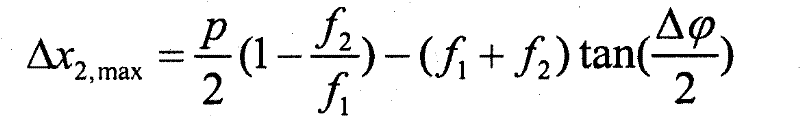
为了完整起见,现在将参考图8提供限定根据本发明各种实施方式的光束控制装置的几何尺寸的参数之间存在的一些关系,以及所得的光束偏转以及光束发散的详细解释。For the sake of completeness, a detailed explanation of some of the relationships that exist between the parameters that define the geometry of beam steering devices according to various embodiments of the invention, and the resulting beam deflection and beam divergence, will now be provided with reference to FIG. 8 .
第二光学元件62相对于第一光学元件61偏移Δx2而产生的光束偏转角θ由下式给出:The beam deflection angle θ produced by the offset of the second
在这个表达式中,f2是包含在第二光学元件62中的透镜64的焦距。In this expression, f 2 is the focal length of the
第二光学元件62相对于第一光学元件61的最大允许的横向偏移Δx2由以下关系得到(假定d≥f1):The maximum permissible lateral offset Δx 2 of the second
在这个关系中,p为透镜间距(被认为对于两个透镜阵列都相同),d为两个光学元件61、62之间的距离,且为入射到光束方向控制装置60的准直光的光束分散。In this relationship, p is the lens pitch (considered to be the same for both lens arrays), d is the distance between the two
在位移Δx2超过这个值的情况下,光线中的一些将会横穿相邻透镜且将会偏转到错误的方向,这导致斑点的鬼影。In case the displacement Δx 2 exceeds this value, some of the light rays will traverse the adjacent lens and will be deflected in the wrong direction, which leads to ghosting of spots.
然后最大的光束位移从下式得到:The maximum beam displacement is then obtained from:
设Δθ为光束发散(比照图7c)。这个光束发散可由以下关系得到:Let Δθ be the beam divergence (cf. Fig. 7c). This beam divergence can be obtained from the following relationship:
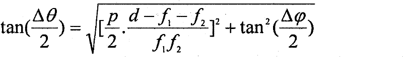
在此,f1为第一光学元件61的透镜63的焦距。Here, f 1 is the focal length of the
很清楚,可通过调整两个光学元件61、62之间的距离而简单地调整光束发散。Clearly, the beam divergence can be adjusted simply by adjusting the distance between the two
也注意到,所有的空间维度与透镜间距p线性地成比例缩放。换言之,透镜间距越小,则获得一定光束偏转或者光束发散所需要的机械位移越小。Note also that all spatial dimensions scale linearly with the lens pitch p. In other words, the smaller the lens pitch, the smaller the mechanical displacement required to obtain a certain beam deflection or beam divergence.
作为只是为示例说明目的而提供的典型示例,考虑以下。设f1=4p,f2=p,且
注意到,当使用浸入式类型的透镜时,原则上f2能够小到f2=p/n,其中n为浸入式材料的折射率。这使得能够增大最大光束位移θmax。Note that when using immersion type lenses, f 2 can in principle be as small as f 2 =p/n, where n is the refractive index of the immersion material. This makes it possible to increase the maximum beam displacement θ max .
鉴于结合图8提供的上述讨论,可导出第一光学元件61的透镜63的焦距可能有利地在透镜间距p的2-10倍范围内,另外,第二光学元件62的透镜64的焦距可能有利地在透镜间距p的0.5-1.5倍范围内。此外,光学元件61、62之间的距离可能有利地在透镜间距p的0-20倍内可调整。In view of the above discussion provided in connection with FIG. 8 , it can be derived that the focal length of the
优选地,透镜间距p可能小于20mm,以保持第二光学元件62相对于第一光学元件61的机械移动在合适的范围内。Preferably, the lens pitch p may be less than 20 mm to keep the mechanical movement of the second
虽然根据本发明的光束方向控制装置的本实施方式主要关于各自包含具有正透镜63、64的透镜阵列的第一61及第二62光学元件进行了描述,应当注意到,其他透镜结构也能够表现的一样好。Although the present embodiment of the beam direction control device according to the invention has been mainly described in relation to the first 61 and second 62 optical elements each comprising a lens array with
在图9a-c中,示出了一个这样的其他透镜配置,在其中第二光学元件62的透镜64为负透镜。In Figs. 9a-c, one such other lens configuration is shown in which the
如从附图明显看出的,这一配置也允许期望的光束方向控制。As is evident from the figures, this configuration also allows the desired beam direction control.
在图10中,示出了又一个透镜配置,在其中第二光学元件62的透镜64基于以下组合:对于每个透镜64的中心位置部分66折射,以及对于每个透镜64的周边部分67全内反射(TIR)。以这种方式,可产生“强”透镜(具有较大数值孔径NA的透镜)。据此,可获得较大的偏转角。In FIG. 10 , yet another lens configuration is shown, in which the
如图10还示出的,第一61和第二62光学元件之间的间隔可能由具有与空气不同的折射率nf的另一光学元件69填充。As also shown in Fig. 10, the space between the first 61 and the second 62 optical element may be filled by another
优选地,另一光学元件69的折射率nf可能接近于第一61和第二62光学元件的折射率(在实际实施中,这可能意味着接近1.5的折射率)。Preferably, the refractive index n f of the further
通过提供另一光学元件69,第二光学元件62中的每个透镜64成为了所谓的浸入式类型透镜,其允许更短的焦距。额外的优势是,能够降低杂散菲涅尔反射。优选地,透镜之间的介质可能为液体或者胶体。By providing a further
另外,如图11a-b示意性地示出的,在所有上述描述的基于透镜的光束控制装置60的示例性示例中,第一光学元件61的透镜表面可能与具有与第一光学元件61的折射率不同但是接近的折射率nf的材料70接触。举例来说,设制成透镜63的材料的折射率为n=1.6。设与透镜表面接触的材料的折射率为nf=1.4。差为An=0.2。结果是与使用空气作为与透镜表面接触的介质的情况相比(An=0.5),透镜阵列的光学质量得以改善。In addition, as shown schematically in FIGS. 11a-b , in all the above-described illustrative examples of lens-based
图12a-c示意性地示出了能够在包含于光束方向控制装置中的第一光学元件61及第二光学元件62中的一个或者两个中使用的一些替代的透镜阵列配置。Figures 12a-c schematically illustrate some alternative lens array configurations that can be used in one or both of the first
图12a示意性地示出了包含多个透镜74的透镜阵列73,每个透镜在其水平及垂直方向上具有不同的尺度,且由此在水平和垂直方向上具有不同的焦距。Figure 12a schematically shows a
图12b示意性地示出了包含多个六角型透镜76的透镜阵列75。FIG. 12 b schematically shows a lens array 75 comprising a plurality of
图12c示意性地示出了包含多个细长型透镜78的透镜阵列77。FIG. 12c schematically shows a lens array 77 comprising a plurality of
最后,现在将参考图13a-b描述根据本发明的光束方向控制装置的第三实施方式。Finally, a third embodiment of the beam direction control device according to the invention will now be described with reference to Figs. 13a-b.
由图13a-b可见,根据该第三实施方式的光束方向控制装置80与先前描述的光束方向控制装置的不同在于:在第一61及第二62光学元件(也参见附图8)之间的第三透镜阵列形式的第三光学元件81。选择第三透镜阵列中的透镜82的焦距使得第三透镜阵列81将第一透镜阵列61映像到第二透镜阵列62上。优选地,第三透镜阵列81放置在第一透镜阵列61的焦平面中,且第一透镜阵列61的焦平面与第二透镜阵列62的焦平面重合。As can be seen from Figures 13a-b, the beam
如图13a所示出的,第三透镜阵列81中的透镜82的作用是生成第一透镜阵列61中的透镜63到第二透镜阵列62中的透镜64上的点对点映像。在一定角度范围内穿过第一光学元件61中的透镜63上的一个点的所有光线都映像到第二光学元件62中的对应透镜64上的一个点上。这样光束在第二光学元件62上的占用面积保持尽可能小。结果,光束角展度并不降低光束方向的最大可允许偏移。As shown in FIG. 13 a , the function of the
第三光学元件81中的透镜82可以有利地具有的焦距f3等于:The
为获得光束的期望的偏转,可相对于第一光学元件61移动第二光学元件62,如图13a中的Δx2所示意性地标示的。在由图13a示出的光束控制状态中,第三光学元件81相对于第一光学元件61并未移位。To obtain the desired deflection of the light beam, the second
如图13a所示出的,第二光学元件62相对于第一光学元件61偏移Δx2而产生的光束偏转角θ的关系由下式给出:As shown in FIG. 13a, the relationship of the beam deflection angle θ produced by the second
最大允许的偏移Δx2由以下关系得到:The maximum permissible offset Δx 2 is obtained from the following relationship:
注意到,不存在包含
然后最大的光束位移从下式得到:The maximum beam displacement is then obtained from:
作为典型示例,考虑以下。设f1=4p,f2=p,且
通过增加第三光学元件81,因而获得了显著增大的最大偏转角。By adding the third optical element 81 a significantly increased maximum deflection angle is thus obtained.
在图13b中,示出了根据本发明本实施方式的光束方向控制装置80处于另一个状态,在其中为了偏转光束,不仅第二光学元件62偏移了Δx2的量,第三光学元件81也偏移了Δx3的量(都是相对于第一光学元件61)。In Fig. 13b, the beam
同样在这种情况下,第二光学元件62相对于第一光学元件61偏移Δx2而产生的光束偏转角θ的关系由下式给出:Also in this case, the relationship of the beam deflection angle θ resulting from the displacement of the second
注意到,有几分意外,Δx3并未进入方程中。但偏移第三光学元件81仍然是有利的,因为其允许第二光学元件62较大的偏移。现在第三光学元件81的角色是同时将第一光学元件61映像到第二光学元件62上且“预”偏转光束。最大允许的偏移Δx3由下式给出:Note that, somewhat unexpectedly, Δx 3 does not enter the equation. However, offsetting the third

最大允许的偏移Δx2由下式给出(假定Δx3=Δx3,max):The maximum permissible offset Δx 2 is given by (assuming Δx 3 =Δx 3,max ):

然后最大的光束位移从以下得到:The maximum beam displacement is then obtained from:
作为典型示例,考虑以下。设f1=4p,f2=p,且
通过允许第三光学元件81相对于第一光学元件61偏移,因而获得了显著增大的最大偏转角。By allowing the third
在本文中,术语“基本”,例如在“基本平行”中,能够为本领域技术人员所理解。类似地,术语“大约”也能够被本领域技术人员理解。在合适时,术语“基本”或者“大约”也可能包括具有“全部”、“完全”、“所有”或者“精确”等的实施方式。因此,在实施方式中,形容词基本可被移除。例如,术语“大约2°”可能也指“2°”。Herein, the term "substantially", such as in "substantially parallel", can be understood by those skilled in the art. Similarly, the term "about" can also be understood by those skilled in the art. Where appropriate, the term "substantially" or "approximately" may also include embodiments having "all", "completely", "all" or "exactly" and the like. Therefore, in an embodiment, the adjective can be substantially removed. For example, the term "about 2°" may also mean "2°."
本领域技术人员能够意识到本发明决不仅限于优选实施方式。举例来说,有利地,可能使用黑色矩阵来覆盖第二光学元件的透镜64之间的区域以获得更大的偏转角度。另外,可能用减反射覆盖层覆盖第一61及第二62光学元件以避免来自透镜阵列表面的杂散菲涅尔反射。另外,有利地,也可能在第一和第二光学元件之间包含另外的光学元件,所述光学元件可能包含上述描述的棱镜板和/或透A person skilled in the art realizes that the present invention is by no means limited to the preferred embodiments. For example, it is advantageously possible to use a black matrix to cover the area between the
镜阵列中的任何一个。在相互不同的独立权利要求中记载一些不同方式的事实并不表明不能利用这些方式的组合。权利要求中的任何附图标记均不应当被解释为对范围的限制。any one of the mirror arrays. The mere fact that several measures are recited in mutually different independent claims does not indicate that a combination of these measures cannot be used to advantage. Any reference signs in the claims should not be construed as limiting the scope.
Claims (15)
Applications Claiming Priority (3)
| Application Number | Priority Date | Filing Date | Title |
|---|---|---|---|
| EP08166168.8 | 2008-10-09 | ||
| EP08166168 | 2008-10-09 | ||
| PCT/IB2009/054322 WO2010041182A1 (en) | 2008-10-09 | 2009-10-02 | Beam direction controlling device and light-output device |
Publications (1)
| Publication Number | Publication Date |
|---|---|
| CN102177448A true CN102177448A (en) | 2011-09-07 |
Family
ID=41327656
Family Applications (1)
| Application Number | Title | Priority Date | Filing Date |
|---|---|---|---|
| CN200980140175XA Pending CN102177448A (en) | 2008-10-09 | 2009-10-02 | Light beam direction control device and light output device |
Country Status (8)
| Country | Link |
|---|---|
| US (1) | US20110280018A1 (en) |
| EP (1) | EP2335098A1 (en) |
| JP (1) | JP2012505428A (en) |
| KR (1) | KR20110069853A (en) |
| CN (1) | CN102177448A (en) |
| RU (1) | RU2508562C2 (en) |
| TW (1) | TW201022719A (en) |
| WO (1) | WO2010041182A1 (en) |
Cited By (8)
| Publication number | Priority date | Publication date | Assignee | Title |
|---|---|---|---|---|
| CN104272010A (en) * | 2012-04-30 | 2015-01-07 | 高通Mems科技公司 | Multi-beam light engine |
| CN106152053A (en) * | 2015-04-09 | 2016-11-23 | 点金石股份有限公司 | Light emitting structure with multi-layer lens and manufacturing method thereof |
| CN106164582A (en) * | 2014-03-04 | 2016-11-23 | 飞利浦灯具控股公司 | Dual Mode Lighting Fixtures |
| CN106796020A (en) * | 2014-04-29 | 2017-05-31 | 陈家铭 | Lighting control system and method |
| CN107504453A (en) * | 2017-09-28 | 2017-12-22 | 赛尔富电子有限公司 | A kind of filter glass, the LED and illuminator with the filter glass |
| CN108716655A (en) * | 2018-06-15 | 2018-10-30 | 东莞华明灯具有限公司 | A kind of orientable lamps and lanterns and hot spot adjusting method for adjusting hot spot |
| CN110325788A (en) * | 2017-01-17 | 2019-10-11 | 昕诺飞控股有限公司 | Adjustable node optical position generates |
| CN113646583A (en) * | 2019-04-08 | 2021-11-12 | 莱迪尔公司 | Optical device for modifying light distribution |
Families Citing this family (33)
| Publication number | Priority date | Publication date | Assignee | Title |
|---|---|---|---|---|
| DE102010044353A1 (en) * | 2010-09-03 | 2012-03-08 | Herbert Waldmann Gmbh & Co. Kg | Floor or table lamp |
| JP5473966B2 (en) * | 2011-03-04 | 2014-04-16 | 三菱電機株式会社 | Light source unit and lighting device |
| CN103251387A (en) * | 2012-01-09 | 2013-08-21 | 三星电子株式会社 | Optical probe and optical coherence tomography apparatus includinge same |
| WO2013132381A1 (en) * | 2012-03-06 | 2013-09-12 | Koninklijke Philips N.V. | Light emitting arrangement |
| WO2013179186A1 (en) | 2012-05-31 | 2013-12-05 | Koninklijke Philips N.V. | A beam direction-controlling device and a light-output device comprising a beam direction-controlling device |
| DE202013101824U1 (en) * | 2013-04-26 | 2014-07-29 | Zumtobel Lighting Gmbh | Luminaire with adjustable light emission characteristic |
| CA2917088A1 (en) * | 2013-07-02 | 2015-01-08 | Koninklijke Philips N.V. | Auto-stereoscopic display device with a striped backlight and two lenticular lens arrays |
| FR3014538B1 (en) * | 2013-12-10 | 2017-08-04 | Yantec | LED BULB |
| EP3132195B1 (en) | 2014-04-11 | 2017-10-18 | Philips Lighting Holding B.V. | Lighting fixture |
| US20160018085A1 (en) * | 2014-07-18 | 2016-01-21 | Soraa, Inc. | Compound light control lens field |
| CN107076392B (en) * | 2014-11-24 | 2019-09-17 | 飞利浦灯具控股公司 | Lighting device and lighting system |
| JP6499908B2 (en) * | 2015-04-23 | 2019-04-10 | 新電元工業株式会社 | Irradiation range setting optical element and illumination device |
| JP6665716B2 (en) * | 2016-06-30 | 2020-03-13 | 三菱電機株式会社 | Light collecting device and lighting device |
| EP3510442B1 (en) * | 2016-09-08 | 2023-11-22 | LensVector Inc. | Liquid crystal dynamic beam control device |
| AU2017375481A1 (en) | 2016-12-16 | 2019-06-20 | Quantum-Si Incorporated | Compact mode-locked laser module |
| AU2017378337A1 (en) * | 2016-12-16 | 2019-06-20 | Quantum-Si Incorporated | Compact beam shaping and steering assembly |
| FR3064758B1 (en) | 2017-03-28 | 2021-04-23 | Compagnie Ind Des Lasers Cilas | OPTICAL DEVICE ABLE TO CHANGE THE DIRECTION OF PROPAGATION OF A LIGHT BEAM |
| EP3438524A1 (en) * | 2017-08-02 | 2019-02-06 | ERCO GmbH | Luminaire |
| NL2019706B1 (en) * | 2017-10-11 | 2019-04-19 | Etap Nv | A lighting unit |
| CN111936788B (en) * | 2017-11-27 | 2023-09-05 | 闪耀光电公司 | Configurable illuminators and widgets |
| TR201722514A2 (en) * | 2017-12-28 | 2019-07-22 | Mylaser Mekanik Elektronik Optik Ve Medikal Sistemleri Ltd Sirketi | LED COLLIMATION SYSTEM WITH DUAL LENS PLANE LAYOUT, FLAMMABLE |
| CN111742106B (en) * | 2018-02-20 | 2022-01-14 | 昕诺飞控股有限公司 | Window with lighting unit |
| US10901227B2 (en) | 2018-02-21 | 2021-01-26 | American Sterilizer Company | Refractive lens array assembly |
| DE102018104746A1 (en) * | 2018-03-01 | 2019-09-05 | Trilux Gmbh & Co. Kg | Floor or table lamp |
| JP7176211B2 (en) * | 2018-03-26 | 2022-11-22 | 東芝ライテック株式会社 | lighting equipment |
| JP6963123B2 (en) * | 2018-05-01 | 2021-11-05 | シグニファイ ホールディング ビー ヴィSignify Holding B.V. | Lighting device with controllable light output characteristics |
| EP3807622A1 (en) | 2018-06-15 | 2021-04-21 | Quantum-Si Incorporated | Data acquisition control for advanced analytic instruments having pulsed optical sources |
| NL2022297B1 (en) * | 2018-12-24 | 2020-07-23 | Schreder Sa | Luminaire system with movable modules |
| JP7267761B2 (en) * | 2019-01-31 | 2023-05-02 | キヤノン株式会社 | Light source device, illumination device, exposure device, and method for manufacturing article |
| KR20220019286A (en) | 2019-06-14 | 2022-02-16 | 퀀텀-에스아이 인코포레이티드 | Slice grating combiner with increased beam alignment sensitivity |
| EP3770491B1 (en) * | 2019-07-24 | 2025-05-21 | Regent Beleuchtungskörper AG | Lighting device |
| WO2021146346A1 (en) | 2020-01-14 | 2021-07-22 | Quantum-Si Incorporated | Amplitude-modulated laser |
| CN117254841B (en) * | 2023-11-15 | 2024-02-02 | 上海卫星互联网研究院有限公司 | Communication methods and devices |
Citations (2)
| Publication number | Priority date | Publication date | Assignee | Title |
|---|---|---|---|---|
| US20030179804A1 (en) * | 2002-03-22 | 2003-09-25 | Cook Lacy G. | Method and laser beam directing system with rotatable diffraction gratings |
| WO2004099849A1 (en) * | 2003-05-12 | 2004-11-18 | Elop Electro-Optics Industries Ltd. | Optical unit and system for steering a light beam |
Family Cites Families (14)
| Publication number | Priority date | Publication date | Assignee | Title |
|---|---|---|---|---|
| JPH07326214A (en) * | 1994-05-31 | 1995-12-12 | Sanyo Electric Co Ltd | Sunlight taking-in device |
| JPH07326213A (en) * | 1994-05-31 | 1995-12-12 | Sanyo Electric Co Ltd | Sunlight taking-in device |
| US4345303A (en) * | 1979-10-02 | 1982-08-17 | Cibie Projecteurs | Optical systems permitting controlled shifting of the beam pattern in headlamps, especially for vehicles |
| FR2570886B1 (en) * | 1984-09-21 | 1987-11-20 | Thomson Csf | ROTARY PRISM SCANNING MICROWAVE ANTENNA |
| GB2200223B (en) * | 1986-01-31 | 1989-06-07 | Ferranti Plc | Apparatus for controlling the direction of a beam of optical radiation |
| US4850686A (en) * | 1987-02-06 | 1989-07-25 | Asahi Kogaku Kogyo K.K. | Apparatus for adjusting light beam direction |
| EP0750728A1 (en) * | 1994-11-17 | 1997-01-02 | CUNNINGHAM, David W. | Lighting device incorporating a zoomable beamspreader |
| JPH1010463A (en) * | 1996-06-25 | 1998-01-16 | Sanyo Electric Co Ltd | Method for attaching lighting prism of sunlight take-in device |
| US6115181A (en) * | 1996-11-22 | 2000-09-05 | 3M Innovative Properties Company | Variable beam splitter having opposed alternating convex and concave lens structures |
| CN1249471C (en) * | 2000-02-01 | 2006-04-05 | J·J·斯奈德 | Single channel M×N fiber optic switch |
| JP2004136307A (en) * | 2002-10-16 | 2004-05-13 | Toshiba Corp | Laser processing method and laser processing apparatus |
| DE502004002696D1 (en) * | 2003-07-24 | 2007-03-08 | Dimitre Tochev | ROOM LIGHTING EQUIPMENT |
| JP4936554B2 (en) * | 2004-03-05 | 2012-05-23 | アイティーティー マニュファクチャリング エンタープライジーズ, インコーポレイテッド | Prism device and optical and radio frequency combined beam steering system |
| US7226185B2 (en) * | 2004-12-23 | 2007-06-05 | 3M Innovative Properties Company | Illumination system with alignment mechanism and method |
-
2009
- 2009-10-02 KR KR1020117010550A patent/KR20110069853A/en not_active Withdrawn
- 2009-10-02 US US13/122,595 patent/US20110280018A1/en not_active Abandoned
- 2009-10-02 JP JP2011530601A patent/JP2012505428A/en active Pending
- 2009-10-02 EP EP09787351A patent/EP2335098A1/en not_active Withdrawn
- 2009-10-02 CN CN200980140175XA patent/CN102177448A/en active Pending
- 2009-10-02 WO PCT/IB2009/054322 patent/WO2010041182A1/en not_active Ceased
- 2009-10-02 RU RU2011118441/28A patent/RU2508562C2/en not_active IP Right Cessation
- 2009-10-06 TW TW098133885A patent/TW201022719A/en unknown
Patent Citations (2)
| Publication number | Priority date | Publication date | Assignee | Title |
|---|---|---|---|---|
| US20030179804A1 (en) * | 2002-03-22 | 2003-09-25 | Cook Lacy G. | Method and laser beam directing system with rotatable diffraction gratings |
| WO2004099849A1 (en) * | 2003-05-12 | 2004-11-18 | Elop Electro-Optics Industries Ltd. | Optical unit and system for steering a light beam |
Cited By (12)
| Publication number | Priority date | Publication date | Assignee | Title |
|---|---|---|---|---|
| CN104272010A (en) * | 2012-04-30 | 2015-01-07 | 高通Mems科技公司 | Multi-beam light engine |
| CN106164582A (en) * | 2014-03-04 | 2016-11-23 | 飞利浦灯具控股公司 | Dual Mode Lighting Fixtures |
| CN106796020A (en) * | 2014-04-29 | 2017-05-31 | 陈家铭 | Lighting control system and method |
| CN106152053A (en) * | 2015-04-09 | 2016-11-23 | 点金石股份有限公司 | Light emitting structure with multi-layer lens and manufacturing method thereof |
| CN110325788A (en) * | 2017-01-17 | 2019-10-11 | 昕诺飞控股有限公司 | Adjustable node optical position generates |
| CN110325788B (en) * | 2017-01-17 | 2021-06-08 | 昕诺飞控股有限公司 | Adjustable nodal position generation |
| US11054108B2 (en) | 2017-01-17 | 2021-07-06 | Signify Holding B.V. | Adjustable spot light position generation |
| CN107504453A (en) * | 2017-09-28 | 2017-12-22 | 赛尔富电子有限公司 | A kind of filter glass, the LED and illuminator with the filter glass |
| CN107504453B (en) * | 2017-09-28 | 2023-11-14 | 赛尔富电子有限公司 | Light filtering lens, LED lamp with light filtering lens and lighting system |
| CN108716655A (en) * | 2018-06-15 | 2018-10-30 | 东莞华明灯具有限公司 | A kind of orientable lamps and lanterns and hot spot adjusting method for adjusting hot spot |
| CN108716655B (en) * | 2018-06-15 | 2023-12-29 | 东莞华明灯具有限公司 | Lamp capable of directionally adjusting light spots and light spot adjusting method |
| CN113646583A (en) * | 2019-04-08 | 2021-11-12 | 莱迪尔公司 | Optical device for modifying light distribution |
Also Published As
| Publication number | Publication date |
|---|---|
| WO2010041182A1 (en) | 2010-04-15 |
| KR20110069853A (en) | 2011-06-23 |
| JP2012505428A (en) | 2012-03-01 |
| US20110280018A1 (en) | 2011-11-17 |
| TW201022719A (en) | 2010-06-16 |
| RU2508562C2 (en) | 2014-02-27 |
| RU2011118441A (en) | 2012-11-20 |
| EP2335098A1 (en) | 2011-06-22 |
Similar Documents
| Publication | Publication Date | Title |
|---|---|---|
| CN102177448A (en) | Light beam direction control device and light output device | |
| US20210389653A1 (en) | Laser light source, wavelength conversion light source, light combining light source, and projection system | |
| US8262252B2 (en) | Illumination system | |
| TWI572955B (en) | Unidirectional grating-based backlighting employing an angularly selective reflective layer | |
| US7967477B2 (en) | Compact optical system and lenses for producing uniform collimated light | |
| US8408751B2 (en) | Light emitting device with concave reflector surfaces | |
| TW200916692A (en) | LED-based luminaire with adjustable beam shape | |
| TW201235620A (en) | Colour-tunable light source unit with phosphor element | |
| US20100118545A1 (en) | Lighting structure | |
| TW201527148A (en) | Vehicle headlight device | |
| CN101073028A (en) | Lighting system | |
| US20150247616A1 (en) | Ring light module | |
| WO2021121318A1 (en) | Optical beam expander lens and lamp | |
| CN105098597B (en) | Correcting system of laser, light source system and projection device | |
| JP6849146B2 (en) | Vehicle lighting | |
| CN102027397A (en) | A directional light source using refractive and reflective optics | |
| US10907774B2 (en) | Light source unit | |
| US11149920B2 (en) | Oval-condenser zoom with independent axis adjustment | |
| WO2015011105A1 (en) | A lens for a light source | |
| TWI547667B (en) | Light-emitting module and light-emitting device | |
| JP2017107768A (en) | Planar illumination device and optical apparatus including the same | |
| JP2016189299A (en) | Surface light source device and display device | |
| US20080298073A1 (en) | Lighting system | |
| JP7046305B2 (en) | Optical and lighting equipment | |
| WO2014006925A1 (en) | Lighting device |
Legal Events
| Date | Code | Title | Description |
|---|---|---|---|
| C06 | Publication | ||
| PB01 | Publication | ||
| C10 | Entry into substantive examination | ||
| SE01 | Entry into force of request for substantive examination | ||
| C12 | Rejection of a patent application after its publication | ||
| RJ01 | Rejection of invention patent application after publication |
Application publication date: 20110907 |