CN102137984B - Sand control screen assembly and method of use - Google Patents
Sand control screen assembly and method of use Download PDFInfo
- Publication number
- CN102137984B CN102137984B CN200980133882.6A CN200980133882A CN102137984B CN 102137984 B CN102137984 B CN 102137984B CN 200980133882 A CN200980133882 A CN 200980133882A CN 102137984 B CN102137984 B CN 102137984B
- Authority
- CN
- China
- Prior art keywords
- radially
- fluid
- sand control
- control screen
- pipe
- Prior art date
- Legal status (The legal status is an assumption and is not a legal conclusion. Google has not performed a legal analysis and makes no representation as to the accuracy of the status listed.)
- Expired - Fee Related
Links
Images


Classifications
-
- E—FIXED CONSTRUCTIONS
- E21—EARTH OR ROCK DRILLING; MINING
- E21B—EARTH OR ROCK DRILLING; OBTAINING OIL, GAS, WATER, SOLUBLE OR MELTABLE MATERIALS OR A SLURRY OF MINERALS FROM WELLS
- E21B43/00—Methods or apparatus for obtaining oil, gas, water, soluble or meltable materials or a slurry of minerals from wells
- E21B43/02—Subsoil filtering
- E21B43/08—Screens or liners
- E21B43/082—Screens comprising porous materials, e.g. prepacked screens
Landscapes
- Engineering & Computer Science (AREA)
- Mining & Mineral Resources (AREA)
- Geology (AREA)
- Life Sciences & Earth Sciences (AREA)
- Fluid Mechanics (AREA)
- Environmental & Geological Engineering (AREA)
- Chemical & Material Sciences (AREA)
- Physics & Mathematics (AREA)
- Dispersion Chemistry (AREA)
- General Life Sciences & Earth Sciences (AREA)
- Geochemistry & Mineralogy (AREA)
- Filtering Materials (AREA)
- Separation Of Solids By Using Liquids Or Pneumatic Power (AREA)
Abstract
一种可操作地置于井眼(50)内的防砂筛管组件(40)。该防砂筛管组件(40)包括基管(42),基管具有位于其侧壁部中的多个开口(46)并具有内部流路(44)。多个可径向延伸的过滤构件(52)各自可操作地与基管(42)的至少一个开口(46)相连。可径向延伸的过滤构件(52)的周向尺寸小于其纵向尺寸。可径向延伸的过滤构件(52)具有径向缩回的行进形态和径向延伸的操作形态;在径向延伸的操作形态下,可径向延伸的过滤构件(52)优选接触井眼(50)。过滤构件(52)还能通过可溶胀材料(48)响应于接触活化流体而延伸。
A sand control screen assembly (40) is operably positioned within a wellbore (50). The sand control screen assembly (40) includes a base pipe (42) having a plurality of openings (46) in a sidewall portion thereof and an internal flow path (44). A plurality of radially extendable filter members (52) are each operably connected to at least one opening (46) of the base pipe (42). The radially extendable filter members (52) have a circumferential dimension that is less than their longitudinal dimension. The radially extendable filter members (52) have a radially retracted travel configuration and a radially extended operational configuration; in the radially extended operational configuration, the radially extendable filter members (52) preferably contact the wellbore (50). The filter members (52) are further extendable in response to contact with an activating fluid by a swellable material (48).
Description
技术领域 technical field
本发明一般涉及对从地层开采出颗粒材料进行控制,并具体地涉及一种具有可径向延伸的过滤构件的防砂筛管组件,该可径向延伸的过滤构件可操作为在激活时接触地层。The present invention relates generally to controlling the extraction of particulate material from a formation, and in particular to a sand control screen assembly having a radially extendable filter member operable to contact a formation when activated .
背景技术 Background technique
不限制本发明的范围,例如参照经由一穿过未烧结或松散烧结的地层的井眼对烃的开采来描述本发明的背景技术。Without limiting the scope of the invention, the background of the invention is described, for example, with reference to the production of hydrocarbons via a wellbore passing through an unsintered or loosely sintered formation.
在地下钻井和完井领域中公知的是,在从穿过未烧结或松散烧结的地层的井开采烃时,会开采出例如砂之类的颗粒材料。开采出这类颗粒材料会导致发生许多问题。例如,颗粒材料导致井内的部件例如油管、流动控制装置和安全装置磨损。另外,颗粒材料会部分或完全地阻塞油井,需要进行昂贵的井大修(workover)。还有,如果颗粒材料被开采到地表,则必须通过地表的处理设施将这些颗粒材料从烃流体中移除。It is well known in the art of subterranean drilling and completions that when producing hydrocarbons from wells passing through green or loosely sintered formations, particulate material such as sand is produced. The mining of such particulate material can lead to a number of problems. For example, particulate material causes wear to components within the well such as tubing, flow control devices, and safety devices. Additionally, the particulate material can partially or completely plug the well, requiring costly well workover. Also, if the particulate material is mined to the surface, it must be removed from the hydrocarbon fluid by surface treatment facilities.
一种用于防止开采出这种颗粒材料的方法是以砾石充填邻近未固结或松散固结的开采层段的井。在典型的砾石充填完井中,将防砂筛管下降到工作管柱上的井眼中,到达最接近期望的开采层段的位置。然后,将包含液体载体和例如砾石之类的颗粒材料的流体浆沿工作管柱向下泵送,并进入防砂筛管与穿孔的井套管或裸眼开采区之间的井内环空(well annulus)。One method used to prevent the production of this granular material is to gravel pack the well adjacent to the unconsolidated or loosely consolidated production interval. In a typical gravel pack completion, the sand control screen is lowered into the wellbore on the workstring to the point closest to the desired production interval. A fluid slurry containing a liquid carrier and particulate material such as gravel is then pumped down the workstring and into the well annulus between the sand control screen and the perforated well casing or open hole production zone. annulus).
流体载体通过流经防砂筛管而流入地层、返回地表,或者两者皆有。在任一种情况下,砾石沉积在防砂筛管周围,以形成砾石充填,这种砾石充填对于烃流体的流动来说是高度地可渗透的,但可阻挡烃流体中所携带的颗粒流动。这样,砾石充填能成功防止与从地层开采出颗粒材料相关联的问题。The fluid carrier flows into the formation, returns to the surface, or both by flowing through the sand control screen. In either case, gravel is deposited around the sand control screen to form a gravel pack that is highly permeable to the flow of hydrocarbon fluids but blocks the flow of particles entrained in the hydrocarbon fluids. In this way, gravel packing can successfully prevent the problems associated with extracting granular material from the formation.
然而,已经发现期望开采层段的完整砾石充填难以实现;在延伸的井眼或倾斜的井眼中,包括具有长的水平开采层段的井眼中,尤其如此。这些未完成的充填通常是液体载体进入开采层段的渗透部而造成砾石脱水,并在环空中形成砂桥的结果。此后,砂桥防止浆流到环空的剩余部分,这样依次防止充足的砾石堆放在开采层段的剩余部分。However, a complete gravel pack of the desired production interval has been found to be difficult to achieve; this is especially true in extended or deviated wellbores, including wellbores with long horizontal production intervals. These incomplete packs are usually the result of gravel dewatering and sand bridge formation in the annulus by liquid carriers entering the permeable portion of the produced interval. Thereafter, the sand bridge prevented slurry from flowing to the remainder of the annulus, which in turn prevented sufficient gravel deposits for the remainder of the produced interval.
另外,已经发现砾石充填在某些裸眼完井中不可行。已经尝试在这种裸眼完井中使用可扩张的金属防砂筛管。这些可扩张的金属防砂筛管典型地安装在井眼中,然后使用穿过筛管的内部的液压冲模(hydraulic swage)或锥体或者其他金属成形技术,径向扩张这些可扩张的金属防砂筛管。除了从地层流体滤出颗粒材料之外,这些可扩张的防砂筛管的一个益处是它们为地层提供径向支撑,这有助于防止地层坍塌。然而,已经发现因为井眼的轮廓并不均匀,所以传统的可扩张的防砂筛管并不是在它们的整个长度上都接触到井眼的壁。更具体地,由于钻井眼的过程和井下岩层的异质性,通常发生冲蚀(washouts)或其他不规则现象,这导致井眼内的某些位置具有比其他区域更大的直径,或者具有非圆形的横截面。因此,当可扩张的防砂筛管扩张时,在可扩张的防砂筛管与井眼的不规则区域之间生成孔隙,这已经导致可扩张的防砂筛管与井眼之间的不完全接触。另外,对于某些传统的可扩张的防砂筛管,螺纹连接件是不可扩张的,这生成非常复杂的轮廓,至少其中一部分防砂筛管不接触井眼。进一步,当传统的可扩张的防砂筛管扩张时,扩张的筛管的径向强度急剧降低,导致对井眼的径向支撑力极小(如果还有的话)。Additionally, gravel packing has been found to be impractical in some open hole completions. Attempts have been made to use expandable metallic sand control screens in such open hole completions. These expandable metal sand control screens are typically installed in the wellbore and then radially expanded using a hydraulic swage or cone or other metal forming technique passing through the interior of the screen . In addition to filtering particulate material from formation fluids, one benefit of these expandable sand control screens is that they provide radial support to the formation, which helps prevent formation collapse. However, it has been found that conventional expandable sand control screens do not contact the wall of the wellbore throughout their entire length because the wellbore's profile is not uniform. More specifically, due to the process of drilling the wellbore and the heterogeneity of the formation downhole, washouts or other irregularities often occur which cause certain locations within the wellbore to have a larger diameter than other areas, or have non-circular cross-section. Consequently, as the expandable sand control screen expands, porosity is created between the expandable sand control screen and irregular areas of the wellbore, which has resulted in incomplete contact between the expandable sand control screen and the wellbore. Additionally, with some conventional expandable sand control screens, the threaded connections are not expandable, which creates very complex profiles where at least a portion of the sand control screen does not contact the wellbore. Further, when a conventional expandable sand control screen is expanded, the radial strength of the expanded screen is drastically reduced, resulting in little, if any, radial support for the wellbore.
因此,需要这样一种防砂筛管组件,其防止从穿越含烃地层的井开采出颗粒材料而无需执行砾石充填操作。还需要这样一种防砂筛管组件,其对地层提供径向支撑而无需扩张金属管。进一步,需要这样一种防砂筛管组件,其适合在长的水平的裸眼完井中操作。Accordingly, there is a need for a sand control screen assembly that prevents the production of particulate material from wells traversing hydrocarbon-bearing formations without performing gravel pack operations. There is also a need for a sand control screen assembly that provides radial support to the formation without expanding the metal pipe. Further, there is a need for a sand control screen assembly suitable for operation in long horizontal open hole completions.
发明内容 Contents of the invention
在此公开的本发明包括一种防砂筛管组件,其防止从穿越含烃地层的井中或作为注入井操作的井中开采出颗粒材料。本发明的防砂筛管组件可取得这种效果而无需执行砾石充填操作。另外,本发明的防砂筛管组件对地层提供了径向支撑而无需扩张金属管。进一步,本发明的防砂筛管组件适合用于长的水平开采层段中的裸眼完井的操作。The invention disclosed herein includes a sand control screen assembly that prevents the production of particulate material from a well traversing a hydrocarbon-bearing formation or operating as an injection well. The sand control screen assembly of the present invention achieves this effect without performing gravel packing operations. In addition, the sand control screen assembly of the present invention provides radial support to the formation without expanding the metal pipe. Further, the sand control screen assembly of the present invention is suitable for operation in open hole completions in long horizontal production intervals.
在一个方案中,本发明致力于一种可操作地置于井眼内的防砂筛管组件。该防砂筛管组件包括基管,该基管具有位于其侧壁部中的至少一个开口并具有内部流路。多个可径向延伸的过滤构件各自可操作地与基管的至少一个开口相连。可径向延伸的过滤构件的周向尺寸小于其纵向尺寸。可径向延伸的过滤构件还具有径向缩回的行进形态和径向延伸的操作形态;在径向延伸的操作形态下,可径向延伸的过滤构件优选紧密接近或接触井眼。In one aspect, the present invention is directed to a sand control screen assembly operatively placed within a wellbore. The sand control screen assembly includes a base pipe having at least one opening in a sidewall portion thereof and having an internal flow path. A plurality of radially extendable filter members are each operatively associated with at least one opening of the base pipe. The circumferential dimension of the radially extendable filter member is smaller than its longitudinal dimension. The radially extendable filter member also has a radially retracted travel configuration and a radially extended operative configuration; in the radially extended operative configuration, the radially extendable filter member is preferably in close proximity or contact with the wellbore.
在一个实施例中,可溶胀材料层布置在基管与可径向延伸的过滤构件的至少一部分之间,由此响应于接触活化流体,可溶胀材料层径向扩张而引起可径向延伸的过滤构件从其行进形态操作到其操作形态。在这个实施例中,活化流体可以是烃流体、水、气或类似材料。In one embodiment, a layer of swellable material is disposed between the base pipe and at least a portion of the radially extendable filter member, whereby in response to contact with the activating fluid, the layer of swellable material radially expands causing the radially extendable The filter member operates from its travel configuration to its operational configuration. In this embodiment, the activation fluid may be a hydrocarbon fluid, water, gas or similar material.
在一个实施例中,可径向延伸的过滤构件包括缸和可径向伸缩的活塞,该缸联结到基管,该可径向伸缩的活塞可滑动地容置在缸内。在某些实施例中,可径向延伸的过滤构件包括过滤挡板(filter retainer)和过滤介质。在其他实施例中,可径向延伸的过滤构件包括穿孔管。与可径向延伸的过滤构件相连的过滤介质可以是单层丝网式筛管、多层丝网式筛管、绕丝筛管、预充填筛管、陶瓷筛管、烧结的或未烧结的金属球或珠或陶瓷球或珠、流体多孔(fluid-porous)的抗颗粒的(particulate resistant)烧结的金属丝网式筛管和流体多孔的抗颗粒的扩散粘合的金属丝网式筛管中的任一种或多种。In one embodiment, the radially extendable filter member includes a cylinder coupled to the base pipe and a radially retractable piston slidably received within the cylinder. In certain embodiments, the radially extendable filter member includes a filter retainer and a filter media. In other embodiments, the radially extendable filter member comprises a perforated tube. The filter media associated with the radially extendable filter elements can be single layer wire screens, multilayer wire screens, wound wire screens, prepacked screens, ceramic screens, sintered or unsintered Metal balls or beads or ceramic balls or beads, fluid-porous particulate resistant sintered wire mesh screens and fluid-porous particle resistant diffusion bonded wire mesh screens any one or more of them.
在一个实施例中,可径向延伸的过滤构件的周向尺寸与纵向尺寸之比至少为1比2。在另一实施例中,可径向延伸的过滤构件的周向尺寸与纵向尺寸之比在约1比2与约1比10之间。在进一步的实施例中,可径向延伸的过滤构件的周向尺寸与纵向尺寸之比在约1比10与约1比30之间。In one embodiment, the ratio of the circumferential dimension to the longitudinal dimension of the radially extendable filter member is at least 1 to 2. In another embodiment, the ratio of the circumferential dimension to the longitudinal dimension of the radially extendable filter member is between about 1 to 2 and about 1 to 10. In a further embodiment, the ratio of the circumferential dimension to the longitudinal dimension of the radially extendable filter member is between about 1 to 10 and about 1 to 30.
在一些实施例中,流体流量控制装置可操作地与每个可径向延伸的过滤构件相连。在其他实施例中,流体流量控制装置可操作地与多个可径向延伸的过滤构件相连。In some embodiments, a fluid flow control device is operatively associated with each radially extendable filter member. In other embodiments, the fluid flow control device is operably connected to a plurality of radially extendable filter members.
在另一方案中,本发明致力于一种可操作地置于井眼内的防砂筛管组件。该防砂筛管组件包括基管,该基管具有位于其侧壁部中的多个开口并具有内部流路。多个可径向延伸的过滤构件各自可操作地与基管的至少一个开口相连。可径向延伸的过滤构件的周向尺寸小于其纵向尺寸。可溶胀材料层布置在基管外,由此响应于接触活化流体,可溶胀材料层径向扩张,进而引起可径向延伸的过滤构件的至少一部分朝向井眼的表面移位,并优选紧密接近或接触井眼的表面。In another aspect, the present invention is directed to a sand control screen assembly operatively placed within a wellbore. The sand control screen assembly includes a base pipe having a plurality of openings in a sidewall portion thereof and having an internal flow path. A plurality of radially extendable filter members are each operatively associated with at least one opening of the base pipe. The circumferential dimension of the radially extendable filter member is smaller than its longitudinal dimension. The layer of swellable material is disposed outside the base pipe, whereby in response to contact with the activating fluid, the layer of swellable material radially expands, thereby causing at least a portion of the radially extendable filter member to displace toward, and preferably in close proximity to, the surface of the wellbore. or contact the surface of the borehole.
在进一步的方案中,本发明致力于一种在井眼中安装防砂筛管组件的方法。该方法包括使防砂筛管组件行进至井眼内的目标位置,防砂筛管组件包括多个可径向延伸的过滤构件,每个可径向延伸的过滤构件可操作地与基管的至少一个开口相连,可径向延伸的过滤构件的周向尺寸小于其纵向尺寸;以及将可径向延伸的过滤构件从径向缩回的行进形态操作到径向延伸的操作形态。In a further aspect, the invention is directed to a method of installing a sand control screen assembly in a wellbore. The method includes advancing a sand control screen assembly to a target location within the wellbore, the sand control screen assembly including a plurality of radially extendable filter members, each radially extendable filter member operatively associated with at least one of the base pipe The openings are connected, the radially extendable filter member has a circumferential dimension smaller than its longitudinal dimension; and the radially extendable filter member is operated from a radially retracted travel configuration to a radially extended operative configuration.
附图说明 Description of drawings
为了更完整地理解本发明的特征和优点,现在连同附图一起参考本发明的详细描述,其中不同附图中的相应附图标记指的是相应部件,其中:For a more complete understanding of the features and advantages of the present invention, reference is now made to the detailed description of the invention taken in conjunction with the accompanying drawings, wherein corresponding reference numerals refer to corresponding parts in the different drawings in which:
图1A是根据本发明的实施例,以行进形态(running configuration)操作多个防砂筛管组件的井系统的示意图;1A is a schematic diagram of a well system operating multiple sand control screen assemblies in a running configuration, in accordance with an embodiment of the present invention;
图1B是根据本发明的实施例,以操作形态(operating configuration)操作多个防砂筛管组件的井系统的示意图;1B is a schematic diagram of a well system operating multiple sand control screen assemblies in an operating configuration, in accordance with an embodiment of the present invention;
图2A是根据本发明的实施例,处于行进形态的防砂筛管组件沿图1A的线2A-2A截取的剖视图;2A is a cross-sectional view of a sand control screen assembly in a traveling configuration taken along line 2A-2A of FIG. 1A in accordance with an embodiment of the present invention;
图2B是根据本发明的实施例,处于操作形态的防砂筛管组件沿图1B的线2B-2B截取的剖视图;2B is a cross-sectional view of a sand control screen assembly in an operational configuration taken along
图3A是根据本发明的实施例,处于行进形态的防砂筛管组件的剖视图;3A is a cross-sectional view of a sand control screen assembly in a traveling configuration, in accordance with an embodiment of the present invention;
图3B是根据本发明的实施例,处于操作形态的防砂筛管组件的剖视图;3B is a cross-sectional view of a sand control screen assembly in an operational configuration, in accordance with an embodiment of the present invention;
图4A是在根据本发明的实施例的防砂筛管组件中使用的可径向延伸的过滤构件的侧视图;4A is a side view of a radially extendable filter member used in a sand control screen assembly according to an embodiment of the present invention;
图4B是在根据本发明的实施例的防砂筛管组件中使用的可径向延伸的过滤构件的前视图;4B is a front view of a radially extendable filter member used in a sand control screen assembly according to an embodiment of the present invention;
图4C是在根据本发明的实施例的防砂筛管组件中使用的可径向延伸的过滤构件的俯视图;4C is a top view of a radially extendable filter member used in a sand control screen assembly according to an embodiment of the invention;
图5A是在根据本发明的实施例的防砂筛管组件中使用的可径向延伸的过滤构件的俯视图;5A is a top view of a radially extendable filter member used in a sand control screen assembly according to an embodiment of the present invention;
图5B是在根据本发明的实施例的防砂筛管组件中使用的可径向延伸的过滤构件的俯视图;5B is a top view of a radially extendable filter member used in a sand control screen assembly according to an embodiment of the invention;
图6A是在根据本发明的实施例的防砂筛管组件中使用的可径向延伸的过滤构件的侧视图;6A is a side view of a radially extendable filter member used in a sand control screen assembly according to an embodiment of the present invention;
图6B是在根据本发明的实施例的防砂筛管组件中使用的可径向延伸的过滤构件的前视图;Figure 6B is a front view of a radially extendable filter member used in a sand control screen assembly according to an embodiment of the present invention;
图6C是在根据本发明的实施例的防砂筛管组件中使用的可径向延伸的过滤构件的侧视图;6C is a side view of a radially extendable filter member used in a sand control screen assembly according to an embodiment of the invention;
图6D是在根据本发明的实施例的防砂筛管组件中使用的可径向延伸的过滤构件的前视图;Figure 6D is a front view of a radially extendable filter member used in a sand control screen assembly according to an embodiment of the present invention;
图7A是在根据本发明的实施例的防砂筛管组件中使用的可径向延伸的过滤构件的前视图;7A is a front view of a radially extendable filter member used in a sand control screen assembly according to an embodiment of the present invention;
图7B是在根据本发明的实施例的防砂筛管组件中使用的可径向延伸的过滤构件的前视图;7B is a front view of a radially extendable filter member used in a sand control screen assembly according to an embodiment of the present invention;
图7C是在根据本发明的实施例的防砂筛管组件中使用的可径向延伸的过滤构件的前视图;7C is a front view of a radially extendable filter member used in a sand control screen assembly according to an embodiment of the invention;
图7D是在根据本发明的实施例的防砂筛管组件中使用的可径向延伸的过滤构件的前视图;Figure 7D is a front view of a radially extendable filter member used in a sand control screen assembly in accordance with an embodiment of the present invention;
图8A是在根据本发明的实施例的防砂筛管组件中使用的可径向延伸的过滤构件的侧视图;8A is a side view of a radially extendable filter member used in a sand control screen assembly according to an embodiment of the present invention;
图8B是在根据本发明的实施例的防砂筛管组件中使用的可径向延伸的过滤构件的前视图;8B is a front view of a radially extendable filter member used in a sand control screen assembly in accordance with an embodiment of the present invention;
图9A是根据本发明的实施例,处在行进形态的防砂筛管组件的剖视图;9A is a cross-sectional view of a sand control screen assembly in a traveling configuration, in accordance with an embodiment of the present invention;
图9B是根据本发明的实施例,处在操作形态的防砂筛管组件的剖视图;9B is a cross-sectional view of a sand control screen assembly in an operational configuration, in accordance with an embodiment of the present invention;
图10A是根据本发明的实施例,处在行进形态的防砂筛管组件的剖视图;10A is a cross-sectional view of a sand control screen assembly in a traveling configuration, in accordance with an embodiment of the present invention;
图10B是根据本发明的实施例,处在操作形态的防砂筛管组件的剖视图;10B is a cross-sectional view of a sand control screen assembly in an operational configuration, in accordance with an embodiment of the present invention;
图11A是根据本发明的实施例,处在行进形态的防砂筛管组件的剖视图;而11A is a cross-sectional view of a sand control screen assembly in a traveling configuration, in accordance with an embodiment of the present invention; and
图11B是根据本发明的实施例,处在操作形态的防砂筛管组件的剖视图。11B is a cross-sectional view of a sand control screen assembly in an operational configuration, in accordance with an embodiment of the present invention.
具体实施方式 Detailed ways
虽然以下详细讨论了形成和使用本发明的各种实施例,但是应理解本发明提供许多可应用的创造性概念,这些创造性概念能够在大量的特定环境下实施。在此讨论的特定实施例仅仅是形成和使用本发明的示例性的特定方式,并非限制本发明的范围。While various embodiments of making and using the invention are discussed in detail below, it should be appreciated that the invention provides many applicable inventive concepts that can be implemented in a wide variety of specific contexts. The specific embodiments discussed herein are merely illustrative of specific ways to make and use the invention, and do not limit the scope of the invention.
首先参考图1A,其中描述了示意性示出并总体用附图标记“10”表示的井系统,其包括体现本发明原理的多个防砂筛管组件。在示出的实施例中,井眼12延伸通过多个地岩层(earth stratum)。井眼12具有基本竖直的区段14,区段14的上部中已经安装有胶结在井眼12内的套管柱16。井眼12还具有基本水平的区段18,区段18延伸通过含烃地层20。如所示出的,井眼12的基本水平的区段18是裸眼。Referring first to FIG. 1A , there is depicted a well system, shown schematically and generally designated by the reference numeral " 10 ", comprising a plurality of sand control screen assemblies embodying the principles of the present invention. In the illustrated embodiment, wellbore 12 extends through a plurality of earth stratum. The wellbore 12 has a substantially vertical section 14 in the upper part of which has been installed a casing string 16 cemented within the wellbore 12 . Wellbore 12 also has a substantially horizontal section 18 that extends through hydrocarbon-bearing formation 20 . As shown, the substantially horizontal section 18 of the wellbore 12 is an open hole.
油管柱22位于井眼22内并从地表延伸。油管柱22提供了用于使地层流体从地层20流向地表的管道。多个防砂筛管组件24位于油管柱22内。防砂筛管组件24被显示为处于行进形态或者说未伸展形态。A tubing string 22 is located within a wellbore 22 and extends from the surface. Tubing string 22 provides a conduit for flow of formation fluids from formation 20 to the surface. A plurality of sand control screen assemblies 24 are located within tubing string 22 . Sand control screen assembly 24 is shown in an advanced or unextended configuration.
再参考图1B,其中描述了图1A的井系统中,防砂筛管组件24处于其操作形态或者说径向扩张形态。如以下更详细解释的,所描述的每个防砂筛管组件24具有基管、多个可径向延伸的过滤构件和可溶胀材料层。一般而言,可溶胀材料层布置在基管周围外侧,可径向延伸的过滤构件布置在可溶胀材料层外。在这种构造中,当防砂筛管组件24接触活化流体,例如烃流体、水或气时,每个防砂筛管组件24的可溶胀材料层径向扩张,这依次引起防砂筛管组件24的可径向延伸的过滤构件接触井眼12的表面。Referring again to FIG. 1B , there is depicted the well system of FIG. 1A with sand control screen assembly 24 in its operative or radially expanded configuration. As explained in more detail below, each sand control screen assembly 24 is depicted having a base pipe, a plurality of radially extendable filter members, and a layer of swellable material. Generally, the layer of swellable material is arranged outside the periphery of the base pipe, and the radially extendable filter member is arranged outside the layer of swellable material. In this configuration, when sand control screen assemblies 24 contact an activating fluid, such as a hydrocarbon fluid, water, or gas, the layer of swellable material of each sand control screen assembly 24 expands radially, which in turn causes sand control screen assemblies 24 to The radially extendable filter member contacts the surface of the wellbore 12 .
虽然图1A-图1B将油管柱22描述为只包括防砂筛管组件24,但是本领域技术人员将认识到,油管柱22可包括任意数量的其他工具和系统,例如流体流量控制装置、通信系统、安全系统等等。使用例如封隔器之类的层位封隔装置,还可将油管柱22分成多个层段。类似于防砂筛管组件24中的可溶胀材料,这些层位封隔装置可由在接触例如无机流体或有机流体这样的流体时膨胀的材料制成。可引起层位封隔装置膨胀并隔离的一些示意性流体包括水、气和烃。Although FIGS. 1A-1B depict tubing string 22 as including only sand control screen assemblies 24, those skilled in the art will recognize that tubing string 22 may include any number of other tools and systems, such as fluid flow control devices, communication systems , security system, etc. The tubing string 22 may also be divided into intervals using zonal isolation devices such as packers. Similar to the swellable material in the sand control screen assembly 24, these zonal isolation devices may be made of a material that swells upon contact with a fluid, such as an inorganic fluid or an organic fluid. Some exemplary fluids that may cause a zonal isolation device to expand and isolate include water, gas, and hydrocarbons.
另外,即使图1A-图1B描述了本发明的防砂筛管组件位于井眼的水平区段中,但是本领域技术人员应理解,本发明的防砂筛管组件同等适用于倾斜的井眼或竖直的井眼。因此,本领域技术人员应理解,使用的方向性术语,例如以上、以下、上部、下部、向上、向下等等是与图中描述的示例性实施例相关联使用的,向上方向为向着相应附图的顶部,而向下方向则是向着相应附图的底部。同样的,虽然图1A-图1B描述了具有单个钻孔的井眼中的本发明的防砂筛管组件,但是本领域技术人员应理解,本发明的防砂筛管组件同等适用于具有一个主井眼和多个分支井眼的多分支井眼(multilateralwellbore)。In addition, even though Figures 1A-1B depict the sand control screen assembly of the present invention in a horizontal section of a wellbore, those skilled in the art will understand that the sand control screen assembly of the present invention is equally applicable to inclined wellbores or vertical boreholes. Straight wellbore. Accordingly, those skilled in the art will understand that when directional terms such as above, below, upper, lower, upward, downward, etc. are used in connection with the exemplary embodiments described in the figures, an upward direction is toward the corresponding The top of the drawing, while the downward direction is towards the bottom of the corresponding drawing. Likewise, although Figures 1A-1B depict the sand control screen assembly of the present invention in a wellbore having a single borehole, those skilled in the art will appreciate that the sand control screen assembly of the present invention is equally applicable to wellbores having one main borehole And a multilateral wellbore with multiple lateral wellbores.
参考图2A和图3A,其中描述了体现本发明的原理并总体用附图标记“40”表示的处在其行进形态的防砂筛管组件的剖视图。防砂筛管组件40包括限定内部流路44的基管42。基管42具有多个开口46。可溶胀材料层48位于基管42周围。可溶胀材料层48通过粘合或其他合适技术附接到基管42。优选地,基于防砂筛管组件40的直径和井眼50的直径来优化可溶胀材料层48的厚度,使得在扩张时,如以下更详细解释的,可溶胀材料层48和可径向延伸的过滤构件52与井眼50的表面之间实现基本均匀的接触。优选地,可径向延伸的过滤构件52围绕防砂筛管组件40周向和纵向分布,并为开采流体从地层进入基管42的内部流路44提供多个基本径直的通道。Referring to Figures 2A and 3A, there are depicted cross-sectional views of a sand control screen assembly embodying principles of the present invention and generally designated by the reference numeral "40" in its advanced configuration. The sand
在示出的实施例中,并如在图4A-图4C中最佳地看到的,每个可径向延伸的过滤构件52包括缸54,缸54通过螺接、焊接、摩擦配合或其他合适的技术附接到基管42。可径向伸缩的活塞56可滑动地置于缸54内。过滤挡板58附接到活塞56的外表面。过滤挡板58支撑过滤介质60。过滤介质60可包括机械滤筛元件,例如具有一层或多层编织金属丝网或纤维网的流体多孔的颗粒限制(particulate restricting)的金属筛管;上述一层或多层编织金属丝网或纤维网可扩散粘合或烧结在一起以构成筛管,该筛管设计为允许流体从中流过但阻止预定大小的颗粒材料流过。在示出的实施例中,过滤介质60包括具有相对常规的(course)金属丝网的外排水层和内排水层,外排水层与内排水层之间设有过滤层,该过滤层具有相对细的筛孔。应注意本发明的防砂筛管组件可与其他类型的过滤介质例如绕丝筛管、预充填筛管、陶瓷筛管、诸如不锈钢珠或烧结的不锈钢珠之类的金属珠等等一起使用。过滤介质60的大小根据将安装过滤介质的开采层段的具体要求来确定。一些示例性的过滤介质60的间隙大小为20-250标准筛孔范围。In the illustrated embodiment, and as best seen in FIGS. 4A-4C , each radially
现在再参考图2B和图3B,其中描述了处在操作形态的防砂筛管组件40的剖视图。在示出的实施例中,可溶胀材料层48已经接触活化流体,例如烃流体、水或气,这已经引起可溶胀材料层48径向扩张而接触井眼50的表面,在示出的实施例中,该表面为地层面(formation face)。另外,可溶胀材料层的48的径向扩张已经引起可径向延伸的过滤构件52接触井眼50的上述表面。Referring now again to FIGS. 2B and 3B , therein are depicted cross-sectional views of sand
本发明的防砂筛管组件提供的一个益处是,除了为地层流体进入内部流路提供多条路径并将颗粒材料滤出地层流体之外,本发明的防砂筛管组件还对地层提供支撑,以防地层坍塌。与上述传统的可扩张的金属防砂筛管相比,本发明的防砂筛管组件提供与地层的改进接触,因为可实现更大的径向扩张;并且可溶胀材料层更贴合(compliant),使得其能够更好符合不均匀的井眼表面。在优选实施方案中,本发明的防砂筛管组件对井眼提供约500psi与约2000psi之间的坍塌支撑力。本领域技术人员将认识到,对于具体的实施方案,本发明提供的坍塌支撑能够通过基管和可溶胀材料层的特定设计特征而得到优化。One benefit provided by the sand control screen assemblies of the present invention is that, in addition to providing multiple paths for formation fluids to enter the internal flow path and filter particulate material out of the formation fluids, the sand control screen assemblies of the present invention provide support to the formation to Prevent ground collapse. Compared to the conventional expandable metal sand control screens described above, the sand control screen assembly of the present invention provides improved contact with the formation because greater radial expansion can be achieved; and the layer of swellable material is more compliant, This allows it to better conform to uneven borehole surfaces. In a preferred embodiment, the sand control screen assembly of the present invention provides a collapse support force of between about 500 psi and about 2000 psi to the wellbore. Those skilled in the art will recognize that the collapse support provided by the present invention can be optimized for a particular embodiment by specific design features of the base tube and swellable material layer.
可用各种技术使可溶胀材料层48与用于引起可溶胀材料层48膨胀的合适的活化流体接触。例如,当防砂筛管组件40安装在井中时,活化流体可能已经出现在井中,在这种情况下,可溶胀材料层48优选包括用于延迟可溶胀材料层48膨胀的机构,例如吸收延迟涂层或薄膜、或防止涂层或薄膜、溶胀延迟材料合成物或类似机构。Contacting the
可替换地,当防砂筛管组件40安装在井中之后,可使活化流体通过井流通到可溶胀材料层48。作为另一替换方案,可从围绕井眼的地层开采进入井眼的活化流体。因此应认识到,根据本发明的原理,可使用引起防砂筛管组件40的可溶胀材料层48发生膨胀的任意方法。Alternatively, an activation fluid may be circulated through the well to the
可溶胀材料层48由接触活化流体例如无机或有机流体时膨胀的一种或多种材料构成。例如,该材料可以是在被刺激材料扩张的活化流体激活时,从其原始尺寸膨胀数倍的聚合物。在一个实施例中,可溶胀材料是在接触和/或吸收烃,例如油或气时膨胀的材料。烃被吸收到可溶胀材料中,使得可溶胀材料的体积增加,而产生可溶胀材料的径向扩张。优选地,可溶胀材料将一直膨胀,直到其外表面和可径向延伸的过滤构件52接触到裸眼完井或下套管井筒中的套管壁中的地层面为止。因此可溶胀材料为使得可径向延伸的过滤构件52径向延伸而与地层接触提供了能量。The layer of
一些示例性可溶胀材料包括弹性聚合物,例如EPDM橡胶、丁苯橡胶、天然橡胶、乙丙橡胶单体(ethylene propylene monomer rubber)、三元乙丙橡胶(ethylene propylene diene monomer rubber)、乙烯醋酸乙烯酯橡胶(ethylene vinyl acetate rubber)、氢化丁腈橡胶、丁腈橡胶、异戊二烯橡胶、氯丁二烯橡胶和聚降冰片烯(polynorbornene)。这些材料及其他可溶胀材料在接触和吸收烃时膨胀,使得可溶胀材料扩张。在一个实施例中,可溶胀材料的橡胶也可溶解有其他材料、或与其他材料机械混合,所述其他材料例如为纤维素(cellulose)纤维。额外的选择可以是橡胶与聚氯乙烯、甲基丙烯酸甲酯、丙烯腈、醋酸乙酯或其他与油接触时扩张的聚合物的机械混合物。Some exemplary swellable materials include elastomeric polymers such as EPDM rubber, styrene-butadiene rubber, natural rubber, ethylene propylene monomer rubber, ethylene propylene diene monomer rubber, ethylene vinyl acetate Ethylene vinyl acetate rubber, hydrogenated nitrile rubber, nitrile rubber, isoprene rubber, chloroprene rubber, and polynorbornene. These and other swellable materials swell upon contact and absorption of hydrocarbons, causing the swellable material to expand. In one embodiment, the rubber of the swellable material may also be dissolved with or mechanically mixed with other materials, such as cellulose fibers. Additional options could be mechanical blends of rubber with polyvinyl chloride, methyl methacrylate, acrylonitrile, ethyl acetate, or other polymers that expand when in contact with oil.
在另一实施例中,可溶胀材料是与水接触时膨胀的材料。在这种情况下,可溶胀材料可以是水溶胀的聚合物,例如水可溶胀的弹性体或水可溶胀的橡胶。更具体地,可溶胀材料可以是水可溶胀疏的疏水聚合物或水可溶胀的疏水共聚物,而且优选为水可溶胀的疏水多孔共聚物。可从许多亲水单体和疏水改性亲水单体制备根据本发明有用的其他聚合物。可利用的特别合适的亲水单体的示例包括但不限于,丙烯酰胺、2-丙烯酰氨基-2-甲基丙磺酸、N,N-二甲基丙烯酰胺、乙烯基吡咯烷酮、甲基丙烯酸二甲基氨基乙酯(dimethylaminoethyl methacrylate)、丙烯酸、甲基丙烯酰氧乙基三甲基氯化铵、二甲氨基丙基甲基丙烯酰胺、甲基丙烯酰胺和丙烯酸羟乙酯。In another embodiment, the swellable material is a material that swells when in contact with water. In this case, the swellable material may be a water-swellable polymer, such as a water-swellable elastomer or a water-swellable rubber. More specifically, the swellable material may be a water-swellable hydrophobic polymer or a water-swellable hydrophobic copolymer, and is preferably a water-swellable hydrophobic porous copolymer. Other polymers useful in accordance with the present invention can be prepared from a number of hydrophilic monomers and hydrophobically modified hydrophilic monomers. Examples of particularly suitable hydrophilic monomers that may be utilized include, but are not limited to, acrylamide, 2-acrylamido-2-methylpropanesulfonic acid, N,N-dimethylacrylamide, vinylpyrrolidone, methyl Dimethylaminoethyl methacrylate, acrylic acid, methacryloyloxyethyltrimethylammonium chloride, dimethylaminopropylmethacrylamide, methacrylamide, and hydroxyethyl acrylate.
也可利用许多疏水改性的亲水单体来构成根据本发明有用的聚合物。特别合适的疏水改性亲水单体包括但不限于,丙烯酸烷基酯、甲基丙烯酸烷基酯、烷基丙烯酰胺和烷基甲基丙烯酰胺(其中烷基具有约4至约22个碳原子)、甲基丙烯酰氧乙基烷基二甲基溴化铵(alkyl dimethylammoniumethylmethacrylate bromide)、甲基丙烯酰氧乙基烷基二甲基氯化铵(alkylimethylammoniumethyl methacrylate chloride)和甲基丙烯酰氧乙基烷基二甲基碘化铵(alkyl dimethylammoniumethyl methacrylate iodide)(其中烷基具有约4至约22个碳原子)以及甲基丙烯酰氨基丙基烷基二甲基溴化铵(alkyldimethylammonium-propylmethacrylamide bromide)、甲基丙烯酰氨基丙基烷基二甲基氯化铵(alkyl dimethylammonium propylmethacrylamide chloride)和甲基丙烯酰氨基丙基烷基二甲基碘化铵(alkyldimethylammonium-propylmethacrylamide iodide)(其中烷基具有约4至约22个碳原子)。A number of hydrophobically modified hydrophilic monomers can also be utilized to form polymers useful in accordance with the present invention. Particularly suitable hydrophobically modified hydrophilic monomers include, but are not limited to, alkyl acrylates, alkyl methacrylates, alkyl acrylamides, and alkyl methacrylamides (wherein the alkyl group has from about 4 to about 22 carbons atom), methacryloyloxyethyl alkyl dimethyl ammonium bromide (alkyl dimethylammonium ethyl methacrylate bromide), methacryloyl oxy ethyl alkyl dimethyl ammonium chloride (alkylimethylammonium ethyl methacrylate chloride) and methacryl oxide Alkyldimethylammoniumethyl methacrylate iodide (wherein the alkyl group has from about 4 to about 22 carbon atoms) and alkyldimethylammonium-propylmethacrylamide bromide), alkyl dimethylammonium propylmethacrylamide chloride and alkyldimethylammonium-propylmethacrylamide iodide (wherein the alkyl having from about 4 to about 22 carbon atoms).
可通过使所述亲水单体中的任一个或多个与所述疏水改性的亲水单体聚合,来制备根据本发明有用的聚合物。聚合反应按本领域技术人员公知的各种方式来执行,例如美国专利第6,476,169号中描述的那些方式,在此就各方面而言其通过援引并入该美国专利。Polymers useful according to the invention can be prepared by polymerizing any one or more of the hydrophilic monomers with the hydrophobically modified hydrophilic monomers. Polymerization reactions are carried out in various ways known to those skilled in the art, such as those described in US Patent No. 6,476,169, which is hereby incorporated by reference for all purposes.
合适的聚合物的估算分子量可处在从约100,000至约10,000,000范围内,并优选处在从约250,000至约3,000,000的范围内,并且亲水分子与疏水改性的亲水单体的摩尔比可处在从约99.98∶0.02至约90∶10的范围内。Suitable polymers can have an estimated molecular weight in the range of from about 100,000 to about 10,000,000, and preferably in the range of from about 250,000 to about 3,000,000, and the molar ratio of hydrophilic molecules to hydrophobically modified hydrophilic monomers can be In the range of from about 99.98:0.02 to about 90:10.
根据本发明有用的其他聚合物包括疏水改性的聚合物、疏水改性的水溶性聚合物及其疏水改性的共聚物。特别合适的疏水改性的聚合物包括但不限于,疏水改性的聚甲基丙烯酸二甲氨基乙酯、疏水改性的聚丙烯酰胺和疏水改性的甲基丙烯酸二甲氨基乙酯和乙烯吡咯烷酮的共聚物。Other polymers useful in accordance with the present invention include hydrophobically modified polymers, hydrophobically modified water-soluble polymers, and hydrophobically modified copolymers thereof. Particularly suitable hydrophobically modified polymers include, but are not limited to, hydrophobically modified polydimethylaminoethyl methacrylate, hydrophobically modified polyacrylamide, and hydrophobically modified dimethylaminoethyl methacrylate and ethylene Copolymers of pyrrolidone.
作为另一示例,可溶胀材料可以是诸如聚丙烯酰胺或改性的交联的聚(甲基)丙烯酸酯的盐聚体,其具有从盐水通过渗透作用吸水的趋势,其中水穿过允许水分子经过但防止溶解的盐通行的半透膜(聚合物与开采流体之间的界面),从低盐浓度的区域(地层水)流向高盐浓度的区域(盐聚体)。As another example, the swellable material may be a salt polymer such as polyacrylamide or a modified cross-linked poly(meth)acrylate, which has a tendency to absorb water from saline by osmosis, where water passes through allowing water Molecules flow from areas of low salt concentration (formation water) to areas of high salt concentration (salt aggregates) through a semipermeable membrane (the interface between the polymer and the production fluid) that prevents the passage of dissolved salt.
在示出的实施例中,可径向延伸的过滤构件52已经被设计成贴合井眼的表面。具体地,可径向延伸的过滤构件52具有相对窄的周向尺寸和相对延伸的纵向尺寸,如在图2A-图2B与图3A-图3B的比较中最佳地看到的。在某些实施例中,可径向延伸的过滤构件52的周向尺寸与纵向尺寸之比在约1比2与约1比10之间。在其他实施例中,可径向延伸的过滤构件52的周向尺寸与纵向尺寸之比在约1比10与1比30之间。In the illustrated embodiment, the radially
另外,可延伸的过滤构件52提供与地层相对大的界面接触面积。具有这样大的界面接触面积,与具有相对小的进入点的流体入口相比,减少了与进入井眼的开采量关联的局部下降(draw down),由此降低了在采油操作中例如水或气这类不希望有的流体发生锥进(coning)的风险。与各个可径向延伸的过滤构件52的流体排放面积或可径向延伸的过滤构件52的收集量相比,相对大的界面接触面积进一步减少了局部下降,如以下更详细解释的。Additionally, the
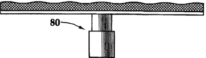
虽然可径向延伸的过滤构件52已经被描述为具有特定的横截面形状,但是本领域技术人员应理解,本发明的可径向延伸的过滤构件可替换地具有不同形状的横截面,包括:圆形,例如图5A的可径向延伸的过滤构件70;矩形,例如图5B的可径向延伸的过滤构件72;以及其他形状,例如椭圆形、正方形、菱形等等,以及其他不对称横截面,所有上述形状都被认为落在本发明的范围内。还有,虽然可径向延伸的过滤构件52被描述为具有波形(contoured)的外表面,但是本领域技术人员应理解,本发明的可径向延伸的过滤构件可替换地具有不同构造的外表面,包括:相对平的外表面,例如图6A-图6B的可径向延伸的过滤构件74、76;不均一的外表面,例如图6C-6D的可径向延伸的过滤构件78、80,等等。Although the radially
虽然可径向延伸的过滤构件52已经被描述为具有附接到过滤挡板的过滤介质,但是本领域技术人员将认识到,可替换地使用其他类型的可径向延伸的过滤构件。例如,如在图7A中最佳地看到的,可径向延伸的过滤构件90包括缸92,缸92通过螺接、焊接、摩擦配合或其他合适的技术附接到基管。可径向伸缩的活塞94可滑动地置于缸92内。管状构件96从活塞94纵向延伸,并具有多个穿孔98。描述为钢球或钢珠或陶瓷球或陶瓷珠的过滤介质100布置在管状构件96内,上述的钢球或钢珠或陶瓷球或陶瓷珠可烧结在管状构件96内。可替换地,过滤介质可以是烧结的或非烧结的、预充填的或树脂覆膜砂(resin coated sand)的、以上组合的单层或多层丝网,或类似的过滤介质。While radially
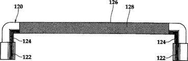
另外,虽然可径向延伸的过滤构件90已经被描述为“T”形的管状构件,但是本领域技术人员将认识到,可替换地使用其他管状构造,并且其他管状构造被认为落在本发明的范围内。例如,如在图7B中最佳地看到的,可径向延伸的过滤构件110是按“L”形形成的。具体地,可径向延伸的过滤构件110包括缸112,缸112通过螺接、焊接、摩擦配合或其他合适技术附接到基管。可径向伸缩的活塞114可滑动地置于缸112内。管状构件116从活塞114纵向延伸,并具有被合适的过滤介质118覆盖的多个穿孔。同样地,如在图7C最佳地看到的,可径向延伸的过滤构件120是按“U”形形成的。具体地,可径向延伸的过滤构件120包括一对缸122,这对缸122通过螺接、焊接、摩擦配合或其他合适技术附接到基管。一对可径向伸缩的活塞126可滑动地置于缸122内。管状构件126在活塞124之间纵向延伸,并具有被合适的过滤介质128覆盖的多个穿孔。进一步,如在图7D中最佳地看到的,可径向延伸的过滤构件130是按“M”形形成的。具体地,可径向延伸的过滤构件130包括三个缸132,这三个缸132通过螺接、焊接、摩擦配合或其他合适技术附接到基管。三个可径向伸缩的活塞134可滑动地置于缸132内。管状构件136在活塞134之间纵向延伸,并具有被一对合适的过滤介质138覆盖的多个穿孔。因此,能够看到为地层流体进入基管的内部流路提供一个或多个径直路径的可径向延伸的过滤构件能够采用许多形状或构造,每种形状或构造都被认为落在本发明的范围内。Additionally, while the radially
再次参考图2A-图4B,在某些实施例中过滤介质60的外层主要起排水层的作用,以允许地层流体在过滤介质60内环向或纵向流动。同样地,过滤介质60的外层还可起化学处理的载体或其他化学剂的作用。使用这种构造是有益的,例如若之前已经在地层的表面上形成滤饼,那么外排水层所提供的隔离(stand off)将防止损坏过滤介质60内的过滤层,并允许使用酸或其他反应流体移除滤饼。Referring again to FIGS. 2A-4B , in some embodiments the outer layer of filter media 60 acts primarily as a drainage layer to allow formation fluids to flow circumferentially or longitudinally within filter media 60 . Likewise, the outer layer of filter media 60 may also function as a carrier for chemical treatments or other chemical agents. Use of this configuration is beneficial, for example, if a filter cake has previously formed on the surface of the formation, then the stand off provided by the outer drainage layer will prevent damage to the filter layer within filter media 60 and allow the use of acid or other The reaction fluid removes the filter cake.
在一个实施例中,过滤介质60的外层中可灌注有反应物质。例如,在安装期间,反应物质可填充过滤介质60的外层中的空隙。优选地,反应物质可在暴露于地下井环境时降解。更优选地,反应物质当暴露于井中的高温水时降解。最优选地,提供如美国专利第7,036,587号所描述的反应物质,在此就各方面而言通过援引并入该美国专利。In one embodiment, the outer layer of filter media 60 may be impregnated with a reactive substance. For example, the reactive species may fill voids in the outer layer of filter media 60 during installation. Preferably, the reactive species degrades upon exposure to the subterranean well environment. More preferably, the reactive species degrades when exposed to high temperature water in the well. Most preferably, a reactive mass is provided as described in US Patent No. 7,036,587, which is hereby incorporated by reference for all purposes.
在某些实施例中,反应物质包括可降解聚合物。根据本发明可使用的合适的可降解聚合物的示例包括:多糖,如葡聚糖或纤维素;甲壳质;壳聚糖、蛋白质;脂肪族聚酯;聚(丙交酯);聚(乙交酯);聚(ε-己内酯)(poly(ε-caprolactones));聚(酐);聚(羟基丁酸盐);脂肪族聚碳酸酯、聚(原酸酯);聚(氨基酸);聚(环氧乙烷)和聚磷腈。在这些合适的聚合物中,脂肪族聚酯例如聚(丙交酯)或聚(乳酸)和聚酐是优选的。In certain embodiments, the reactive species includes a degradable polymer. Examples of suitable degradable polymers that may be used according to the invention include: polysaccharides such as dextran or cellulose; chitin; chitosan, proteins; aliphatic polyesters; poly(lactide); lactides); poly(ε-caprolactones) (poly(ε-caprolactones)); poly(anhydrides); poly(hydroxybutyrates); aliphatic polycarbonates, poly(orthoesters); poly(amino acids ); poly(ethylene oxide) and polyphosphazenes. Of these suitable polymers, aliphatic polyesters such as poly(lactide) or poly(lactic acid) and polyanhydrides are preferred.
反应物质可在出现含水合的(hydrated)有机或无机化合物固体时降解,上述水合的有机或无机化合物固体可包含在防砂筛管组件40中,因此当安装筛管时井中有水源。可替换地,可在防砂筛管组件40被运送到井中之后,例如通过将水源向下通到井中而将另一水源送到反应物质,或者将地层水用作水源。The reactive mass can degrade in the presence of hydrated organic or inorganic compound solids which can be contained in the sand
接下来参考图8A-图8B,其中描述了体现本发明的原理并总体用附图标记“140”表示的防砂筛管组件中使用的可径向延伸的过滤构件的侧视图和前视图(部分剖视图)。可径向延伸的过滤构件140包括缸142,缸142通过例如那些在此讨论的合适技术附接到基管。可径向伸缩的活塞144可滑动地置于缸142内。过滤挡板146附接到活塞144的外表面。过滤挡板146支撑过滤介质148。过滤介质148可包括机械滤筛元件,例如在此讨论的那些机械滤筛元件。如上所述,与进入相对小的进入点的开采量相比,过滤介质148提供的大界面接触面积减少了与进入井眼的开采量关联的局部下降。通过过滤介质148和地层的界面接触面积与可径向延伸的过滤构件148的流体排放面积之间相对大的比值,强化了这一益处。通过为经过可径向延伸的过滤构件148的流体提供相对窄的或限制性的出口路径能够实现大比值。通过将流体流量控制装置150定位在过滤介质148的出口路径内,例如示出的缸142或活塞144内,可优化比值。在这个实施例中,利用流体流量控制装置150,通过可径向延伸的过滤构件148来控制开采率。例如,流体流量控制装置150可采用流入控制装置的形式,例如喷嘴、流量管、节流孔或其他限流器。Referring next to FIGS. 8A-8B , there are depicted side and front views (in part) of a radially extendable filter member used in a sand control screen assembly embodying principles of the present invention and generally designated by the reference numeral "140". cutaway view). The radially
可替换地,根据期望的操作,流体流量控制装置150可采用许多其他形式。例如,可能期望暂时阻止流体流经可径向延伸的过滤构件148。在这种情况下,流体流量控制装置150可以是由砂、盐、蜡、铝、锌或类似材料构成的可溶解的塞子、可移除的塞子或可剪切的塞子,或者可以是压力激活的装置例如爆破片(burst disk)。作为另一实施例,可能期望在包括可径向延伸的过滤构件148的防砂筛管组件内进行高压操作期间,阻止进入地层的流体损失,在这种情况下,流体流量控制装置150可以是单向阀或止回阀。作为又一示例,可能期望控制进入包括可径向延伸的过滤构件148的防砂筛管组件的流体的类型,在这种情况下,流体流量控制装置150可以是开采控制装置,例如响应于接触不期望的流体(例如水)而关闭的阀。这种阀可被可溶胀材料(包括那些以上讨论的可溶胀材料、有机纤维、渗透单元(osmoticcell)或类似材料)激活。Alternatively, fluid
接下来参考图9A,其中描述了体现本发明的原理并总体用附图标记“160”表示的处在行进形态的防砂筛管组件。防砂筛管组件160包括基管162和内套筒164,内套管164包括多个开口166并限定内部流路168。基管162具有多个开口170。可溶胀材料层172位于基管162周围。可溶胀材料层172通过粘合或其他合适技术附接到基管162。防砂筛管组件160包括多个可径向延伸的过滤构件174,这些可径向延伸的过滤构件174按在此描述的方式构造和操作,并在多个纵向位置围绕可溶胀材料层172周向分布。如上所述,可溶胀材料层172激活时,使得可延伸的过滤构件174接触井眼176,如在图9B中最佳地看到的。Referring next to FIG. 9A , there is depicted a sand control screen assembly embodying principles of the present invention and generally designated by the reference numeral " 160 " in a traveling configuration. Sand
一对流体流量控制装置178、180布置在基管162与套筒164之间。如上所述,根据期望的操作,流体流量控制装置178、180可采用许多形式,包括可溶解的塞子、可移除的塞子或可剪切的塞子、爆破片、单向阀、止回阀、喷嘴、流量管、节流孔或其他限流器、响应于接触不期望的流体而关闭的阀等等的任意组合。在这个实施例中,通过多个可径向延伸的过滤构件174的开采物在基管162与套筒164之间限定的公共环形腔或者说歧管182中混合。这提供了均匀的生产压差(draw down)施加在防砂筛管组件160的整个长度和周向上的益处。如果期望有不受限制的流动,则在某些实施例中,套筒164是可通过机械或化学工具移除的。A pair of fluid
额外地或替换性地,滑动套筒(未示出)可操作地与套筒164和开口166相连。滑动套筒可布置在套筒164之内,处于内部流路168的内部,或者可优选布置在套筒164之外,处于环形腔182的内部。滑动套筒可具有打开位置和闭合位置,其中打开位置允许流体流经开口166,闭合位置则阻止流体流经开口166。另外,滑动套筒的位置可平滑调整,使得滑动套筒可提供阻止功能。滑动套筒可机械式地、电子式地、液力式地或通过其他合适的工具来操作。Additionally or alternatively, a sliding sleeve (not shown) is operatively connected to
参考图10A,其中描述了体现本发明的原理并总体用附图标记“190”表示的处在行进形态的防砂筛管组件的剖视图。防砂筛管组件190包括限定内部流路194的基管192。基管192具有多个开口196,每个开口196具有与之相连的可径向延伸的过滤构件198。优选地,可径向延伸的过滤构件198围绕防砂筛管组件190周向和纵向分布,以便为从地层到基管192的内部流路194的开采流体提供多个基本径直的通路。Referring to Figure 10A, there is depicted a cross-sectional view of a sand control screen assembly in a traveling configuration embodying principles of the present invention and generally designated by the reference numeral "190". Sand
每个可径向延伸的过滤构件198包括缸200,缸200通过螺接、焊接、摩擦配合或其他合适技术附接到基管192。可径向伸缩的活塞202可滑动地置于缸200内。过滤挡板204附接到活塞202的外表面。过滤挡板204支撑外过滤构件206。如示出的,外过滤构件206是机械滤筛元件,例如为编织金属丝网或纤维丝网。另外,第二滤筛元件208布置在活塞202内,第二滤筛元件208例如为预充填的或树脂覆膜砂的金属球或金属珠或陶瓷球或陶瓷珠,这些金属球或金属珠或陶瓷球或陶瓷珠可烧结或未烧结或经类似处理。可径向延伸的过滤构件198还包括流体流量控制装置210。在这个不包括可溶胀材料层的实施例中,防砂筛管组件190的内部流路194内的压力被优选用来使可径向延伸的过滤构件198从其行进位置移动到其操作位置,如在图10B中最佳对看到的。因此,流体流量控制装置210优选为可溶解的塞子、可移除的塞子或可剪切的塞子、爆破片、单向阀、止回阀或其他装置中的一种,所述其他装置将允许内部流路194加压并且还将允许开采流体从地层通过流体流量控制装置210进入内部流路194。Each radially
参考图11A,其中描述了体现本发明的原理并总体用附图标记“220”表示的处在行进形态的防砂筛管组件的剖视图。防砂筛管组件220包括限定内部流路224的基管222。基管222具有多个开口226,每个开口226具有与之相连的可径向延伸的过滤构件228。优选地,可径向延伸的过滤构件228围绕防砂筛管组件220周向和纵向分布,以便为开采流体从地层到基管222的内部流路224提供多个基本径直的通路。Referring to FIG. 11A, there is depicted a cross-sectional view of a sand control screen assembly in a traveling configuration embodying principles of the present invention and generally designated by the reference numeral "220". Sand
每个可径向延伸的过滤构件228包括缸230,缸230通过螺接、焊接、摩擦配合或其他合适技术附接到基管222。可径向伸缩的活塞232可滑动地置于缸230内。纵向延伸的穿孔管状构件234附接到每个活塞232的外表面。滤筛元件236布置在管状构件234内,滤筛元件236例如为预充填的或树脂覆膜砂的金属球或金属珠或陶瓷球或陶瓷珠,这些金属球或金属珠或陶瓷球或陶瓷珠可烧结或未烧结或经类似处理。可径向延伸的过滤构件228包括一对流体流量控制装置238。因为这个实施例不包括可溶胀材料层,所以优选利用防砂筛管组件220的内部流路224内的压力来使可径向延伸的过滤构件228从其行进位置移动到其操作位置,如在图11B中最佳地看到的。因此,流体流量控制装置238优选为可溶解的塞子、可移除的塞子或可剪切的塞子、爆破片、单向阀、止回阀或其他装置中的一种,所述其他装置将允许内部流路224加压并且还将允许开采流体从地层通过流体流量控制装置238进入内部流路224。Each radially
虽然已经参考示例性实施例描述了本发明,但是不希望在限制意义上解释本说明书。参考本说明书,示例性实施例以及本发明的其他实施例的各种更改和组合对本领域技术人员而言将是明显的。因此,希望所附权利要求涵盖任何这种更改或实施例。While this invention has been described with reference to exemplary embodiments, this description is not intended to be construed in a limiting sense. Various modifications and combinations of the exemplary embodiments, as well as other embodiments of the invention, will be apparent to persons skilled in the art upon reference to the description. It is therefore intended that any such modifications or embodiments be covered by the appended claims.
Claims (10)
Priority Applications (1)
| Application Number | Priority Date | Filing Date | Title |
|---|---|---|---|
| CN201410332448.3A CN104131801B (en) | 2008-08-29 | 2009-08-25 | A kind of method installing sand control screen in the wellbore |
Applications Claiming Priority (3)
| Application Number | Priority Date | Filing Date | Title |
|---|---|---|---|
| US12/201,655 US7866383B2 (en) | 2008-08-29 | 2008-08-29 | Sand control screen assembly and method for use of same |
| US12/201,655 | 2008-08-29 | ||
| PCT/US2009/054951 WO2010025152A1 (en) | 2008-08-29 | 2009-08-25 | Sand control screen assembly and method for use of same |
Related Child Applications (1)
| Application Number | Title | Priority Date | Filing Date |
|---|---|---|---|
| CN201410332448.3A Division CN104131801B (en) | 2008-08-29 | 2009-08-25 | A kind of method installing sand control screen in the wellbore |
Publications (2)
| Publication Number | Publication Date |
|---|---|
| CN102137984A CN102137984A (en) | 2011-07-27 |
| CN102137984B true CN102137984B (en) | 2014-06-18 |
Family
ID=41188012
Family Applications (2)
| Application Number | Title | Priority Date | Filing Date |
|---|---|---|---|
| CN201410332448.3A Expired - Fee Related CN104131801B (en) | 2008-08-29 | 2009-08-25 | A kind of method installing sand control screen in the wellbore |
| CN200980133882.6A Expired - Fee Related CN102137984B (en) | 2008-08-29 | 2009-08-25 | Sand control screen assembly and method of use |
Family Applications Before (1)
| Application Number | Title | Priority Date | Filing Date |
|---|---|---|---|
| CN201410332448.3A Expired - Fee Related CN104131801B (en) | 2008-08-29 | 2009-08-25 | A kind of method installing sand control screen in the wellbore |
Country Status (8)
| Country | Link |
|---|---|
| US (1) | US7866383B2 (en) |
| EP (1) | EP2324191A1 (en) |
| CN (2) | CN104131801B (en) |
| AU (1) | AU2009285796B2 (en) |
| BR (1) | BRPI0913171A2 (en) |
| MX (1) | MX2011002141A (en) |
| MY (1) | MY149750A (en) |
| WO (1) | WO2010025152A1 (en) |
Families Citing this family (73)
| Publication number | Priority date | Publication date | Assignee | Title |
|---|---|---|---|---|
| EP2087199A4 (en) * | 2006-11-15 | 2015-09-16 | Halliburton Energy Services Inc | Well tool including swellable material and integrated fluid for initiating swelling |
| DK2129865T3 (en) | 2007-02-06 | 2019-01-28 | Halliburton Energy Services Inc | Swellable packer with enhanced sealing capability |
| US7841409B2 (en) * | 2008-08-29 | 2010-11-30 | Halliburton Energy Services, Inc. | Sand control screen assembly and method for use of same |
| US7814973B2 (en) | 2008-08-29 | 2010-10-19 | Halliburton Energy Services, Inc. | Sand control screen assembly and method for use of same |
| US7984762B2 (en) * | 2008-09-25 | 2011-07-26 | Halliburton Energy Services, Inc. | Pressure relieving transition joint |
| US20100230100A1 (en) * | 2009-03-13 | 2010-09-16 | Reservoir Management Inc. | Plug for a Perforated Liner and Method of Using Same |
| US8079416B2 (en) * | 2009-03-13 | 2011-12-20 | Reservoir Management Inc. | Plug for a perforated liner and method of using same |
| US8047298B2 (en) * | 2009-03-24 | 2011-11-01 | Halliburton Energy Services, Inc. | Well tools utilizing swellable materials activated on demand |
| US8826985B2 (en) * | 2009-04-17 | 2014-09-09 | Baker Hughes Incorporated | Open hole frac system |
| US8302680B2 (en) | 2009-08-12 | 2012-11-06 | Halliburton Energy Services, Inc. | Swellable screen assembly |
| US8256510B2 (en) | 2009-08-12 | 2012-09-04 | Halliburton Energy Services, Inc. | Control screen assembly |
| CA2801594C (en) * | 2010-06-14 | 2016-05-03 | Tage Thorkildsen | Method and apparatus for use with an inflow control device |
| US9464500B2 (en) | 2010-08-27 | 2016-10-11 | Halliburton Energy Services, Inc. | Rapid swelling and un-swelling materials in well tools |
| US8851180B2 (en) * | 2010-09-14 | 2014-10-07 | Halliburton Energy Services, Inc. | Self-releasing plug for use in a subterranean well |
| GB201019358D0 (en) * | 2010-11-16 | 2010-12-29 | Darcy Technologies Ltd | Downhole method and apparatus |
| US8695622B2 (en) * | 2011-04-18 | 2014-04-15 | Halliburton Energy Services, Inc. | Ball valve safety plug |
| US20120325323A1 (en) * | 2011-06-23 | 2012-12-27 | Baker Hughes Incorporated | Production system and method of varying restrictions to flow along the same |
| BR112013033024A2 (en) * | 2011-06-24 | 2017-06-27 | Prad Res & Development Ltd | system, and method |
| NO333258B1 (en) * | 2011-09-13 | 2013-04-22 | Geir Habesland | Tool and method for centering the feeding rudder |
| EP2761122B1 (en) * | 2011-09-27 | 2016-09-21 | Baker Hughes Incorporated | Method and system for hydraulic fracturing |
| WO2013055362A1 (en) | 2011-10-14 | 2013-04-18 | Halliburton Energy Services, Inc. | Well screen with extending filter |
| EP2751381A4 (en) * | 2011-12-21 | 2016-03-16 | Halliburton Energy Services Inc | Downhole fluid flow control system having temporary sealing substance and method for use thereof |
| US8925633B2 (en) * | 2012-01-13 | 2015-01-06 | Baker Hughes Incorporated | Inflow control device with adjustable orifice and production string having the same |
| EP2631423A1 (en) * | 2012-02-23 | 2013-08-28 | Services Pétroliers Schlumberger | Screen apparatus and method |
| IN2014DN08973A (en) * | 2012-05-10 | 2015-05-22 | Halliburton Energy Services Inc | |
| MY181138A (en) * | 2012-06-28 | 2020-12-18 | Halliburton Energy Services Inc | Swellable screen assembly with inflow control |
| US9273537B2 (en) * | 2012-07-16 | 2016-03-01 | Schlumberger Technology Corporation | System and method for sand and inflow control |
| US9151143B2 (en) * | 2012-07-19 | 2015-10-06 | Halliburton Energy Services, Inc. | Sacrificial plug for use with a well screen assembly |
| US9016365B2 (en) * | 2012-09-19 | 2015-04-28 | Halliburton Energy Services, Inc. | Expandable screen by spring force |
| US8881804B2 (en) * | 2012-09-19 | 2014-11-11 | Halliburton Energy Services, Inc. | Expandable screen by spring force |
| GB2526962B (en) | 2013-04-01 | 2017-08-16 | Halliburton Energy Services Inc | Well screen assembly with extending screen |
| US9027637B2 (en) * | 2013-04-10 | 2015-05-12 | Halliburton Energy Services, Inc. | Flow control screen assembly having an adjustable inflow control device |
| US9970269B2 (en) | 2013-06-28 | 2018-05-15 | Halliburton Energy Services, Inc. | Expandable well screen having enhanced drainage characteristics when expanded |
| WO2014209388A1 (en) * | 2013-06-28 | 2014-12-31 | Halliburton Energy Services, Inc. | Expandable well screen having enhanced drainage characteristics when expanded |
| WO2015013582A1 (en) | 2013-07-25 | 2015-01-29 | Schlumberger Canada Limited | Sand control system and methodology |
| WO2015069295A1 (en) * | 2013-11-11 | 2015-05-14 | Halliburton Energy Services, Inc. | Internal adjustments to autonomous inflow control devices |
| US10294761B2 (en) | 2013-11-25 | 2019-05-21 | Halliburton Energy Services, Inc. | Erosion modules for sand screen assemblies |
| US20150152716A1 (en) * | 2013-12-03 | 2015-06-04 | Chevron U.S.A. Inc. | Method, System and Apparatus of Erosion Resistant Filtering Screen Structures |
| US9790766B2 (en) | 2013-12-17 | 2017-10-17 | Halliburton Energy Services, Inc. | Internal adjustments to autonomous inflow control devices |
| GB201323127D0 (en) | 2013-12-30 | 2014-02-12 | Darcy Technologies Ltd | Downhole apparatus |
| GB201323121D0 (en) | 2013-12-30 | 2014-02-12 | Darcy Technologies Ltd | Downhole Apparatus |
| US9695675B2 (en) | 2014-01-03 | 2017-07-04 | Weatherford Technology Holdings, Llc | High-rate injection screen assembly with checkable ports |
| US9677388B2 (en) * | 2014-05-29 | 2017-06-13 | Baker Hughes Incorporated | Multilateral sand management system and method |
| US10227850B2 (en) * | 2014-06-11 | 2019-03-12 | Baker Hughes Incorporated | Flow control devices including materials containing hydrophilic surfaces and related methods |
| GB2546209B (en) | 2014-10-28 | 2020-11-25 | Halliburton Energy Services Inc | Downhole state-machine-based monitoring of vibration |
| WO2016105398A1 (en) * | 2014-12-23 | 2016-06-30 | Halliburton Energy Services, Inc. | Prepacked sand screen assemblies |
| CN106150413A (en) * | 2015-04-10 | 2016-11-23 | 思达斯易能源技术(集团)有限公司 | A kind of sand control cap and there is the hanger of this sand control cap |
| CN106677747A (en) * | 2017-01-19 | 2017-05-17 | 长江大学 | Filling type water control screen pipe used for sand prevention of horizontal well completion |
| GB2574540B (en) * | 2017-05-01 | 2021-10-20 | Halliburton Energy Services Inc | Well screen assembly and method of use thereof |
| GB2562235B (en) * | 2017-05-08 | 2021-07-07 | Reactive Downhole Tools Ltd | Swellable conformance tool |
| US20180328139A1 (en) * | 2017-05-12 | 2018-11-15 | Weatherford Technology Holdings, Llc | Temporary Barrier for Inflow Control Device |
| CN107510977B (en) * | 2017-08-31 | 2023-01-24 | 中国地质科学院地质力学研究所 | Special filter for measuring hydraulic fracturing stress |
| CN107990294B (en) * | 2018-01-10 | 2024-01-12 | 宋晓轩 | Steam production device deep into dry-hot rock stratum |
| CN110242232A (en) * | 2018-03-09 | 2019-09-17 | 成都汉科石油技术有限公司 | A kind of tubing string and construction technology having cleaned well for high temperature and pressure oil/gas well |
| WO2020027772A1 (en) * | 2018-07-30 | 2020-02-06 | Halliburton Energy Services, Inc. | Inflow control device with dissolvable plugs |
| CN109505567B (en) * | 2018-11-16 | 2019-08-23 | 大庆市天德忠石油科技有限公司 | A kind of bridge-type screen casing |
| MY207681A (en) | 2019-02-20 | 2025-03-12 | Schlumberger Technology Bv | Non-metallic compliant sand control screen |
| CN109779567B (en) * | 2019-03-10 | 2021-06-15 | 辽宁石油化工大学 | A well completion device for oil and gas wells |
| CN110201429B (en) * | 2019-06-28 | 2024-06-07 | 昌登宇 | Filter and method for removing byproduct paraffin in methanol production by filtering |
| CN110984917A (en) * | 2019-11-15 | 2020-04-10 | 中国海洋石油集团有限公司 | Production-increasing water-controlling sand-preventing well completion method for low-permeability reservoir |
| US11255160B2 (en) | 2019-12-09 | 2022-02-22 | Saudi Arabian Oil Company | Unblocking wellbores |
| CN110984924B (en) * | 2019-12-20 | 2021-08-24 | 新疆恒智伟业石油工程技术开发有限公司 | A construction method for an open-hole completion string that is easy to drill and grind |
| CN110984938A (en) * | 2019-12-23 | 2020-04-10 | 中国石油大学(华东) | Novel flow-guiding thermosensitive perforating hole |
| WO2021144606A1 (en) * | 2020-01-14 | 2021-07-22 | Miri Ramezan | Sand control system of oil reservoirs |
| CN114075954B (en) * | 2020-08-20 | 2024-06-14 | 中国石油化工股份有限公司 | Anti-blocking Gao Shenlv sand pipe |
| US11352867B2 (en) | 2020-08-26 | 2022-06-07 | Saudi Arabian Oil Company | Enhanced hydrocarbon recovery with electric current |
| US12078035B2 (en) | 2020-10-13 | 2024-09-03 | Schlumberger Technology Corporation | Elastomer alloy for intelligent sand management |
| CN114542023B (en) * | 2020-11-24 | 2024-06-25 | 中国石油天然气股份有限公司 | A flushable and unblockable elastic screen pipe and unblocking sand filter column |
| GB2615007B (en) * | 2020-12-09 | 2024-10-16 | Halliburton Energy Services Inc | Filter plug to prevent proppant flowback |
| US11608723B2 (en) | 2021-01-04 | 2023-03-21 | Saudi Arabian Oil Company | Stimulated water injection processes for injectivity improvement |
| US11421148B1 (en) | 2021-05-04 | 2022-08-23 | Saudi Arabian Oil Company | Injection of tailored water chemistry to mitigate foaming agents retention on reservoir formation surface |
| WO2022241355A1 (en) * | 2021-05-13 | 2022-11-17 | Halliburton Energy Services, Inc. | Metal-matrix downhole sand screens |
| US11993746B2 (en) | 2022-09-29 | 2024-05-28 | Saudi Arabian Oil Company | Method of waterflooding using injection solutions containing dihydrogen phosphate |
Citations (8)
| Publication number | Priority date | Publication date | Assignee | Title |
|---|---|---|---|---|
| US2945541A (en) * | 1955-10-17 | 1960-07-19 | Union Oil Co | Well packer |
| US2981333A (en) * | 1957-10-08 | 1961-04-25 | Montgomery K Miller | Well screening method and device therefor |
| US3390724A (en) * | 1966-02-01 | 1968-07-02 | Zanal Corp Of Alberta Ltd | Duct forming device with a filter |
| US5165478A (en) * | 1991-09-16 | 1992-11-24 | Conoco Inc. | Downhole activated process and apparatus for providing cathodic protection for a pipe in a wellbore |
| US20050126776A1 (en) * | 2003-12-10 | 2005-06-16 | Russell Thane G. | Wellbore screen |
| US20050284633A1 (en) * | 2004-06-14 | 2005-12-29 | Baker Hughes Incorporated | One trip well apparatus with sand control |
| US20080032349A1 (en) * | 2004-09-08 | 2008-02-07 | Aventis Pharma S.A. | Method for producing k5 polysaccharide |
| CN101910553A (en) * | 2008-01-08 | 2010-12-08 | 哈利伯顿能源服务公司 | Sand control screen assembly and method for use of same |
Family Cites Families (83)
| Publication number | Priority date | Publication date | Assignee | Title |
|---|---|---|---|---|
| US921337A (en) | 1908-09-24 | 1909-05-11 | William Alexander Archer | Well-screen. |
| US1811235A (en) | 1926-01-15 | 1931-06-23 | Walter E King | Well screen |
| GB8412423D0 (en) | 1984-05-16 | 1984-06-20 | Allied Colloids Ltd | Polymeric compositions |
| US4585064A (en) | 1984-07-02 | 1986-04-29 | Graham John W | High strength particulates |
| US5249627A (en) | 1992-03-13 | 1993-10-05 | Halliburton Company | Method for stimulating methane production from coal seams |
| GB9426025D0 (en) | 1994-12-22 | 1995-02-22 | Smith Philip L U | Oil and gas field chemicals |
| WO1996020970A1 (en) | 1994-12-29 | 1996-07-11 | Henkel Corporation | Aqueous self-dispersible epoxy resin based on epoxy-amine adducts |
| US5839510A (en) | 1995-03-29 | 1998-11-24 | Halliburton Energy Services, Inc. | Control of particulate flowback in subterranean wells |
| US5775425A (en) | 1995-03-29 | 1998-07-07 | Halliburton Energy Services, Inc. | Control of fine particulate flowback in subterranean wells |
| US5833000A (en) | 1995-03-29 | 1998-11-10 | Halliburton Energy Services, Inc. | Control of particulate flowback in subterranean wells |
| GB9619418D0 (en) | 1996-09-18 | 1996-10-30 | Urlwin Smith Phillip L | Oil and gas field chemicals |
| EP0909875A3 (en) | 1997-10-16 | 1999-10-27 | Halliburton Energy Services, Inc. | Method of completing well in unconsolidated subterranean zone |
| US6481494B1 (en) | 1997-10-16 | 2002-11-19 | Halliburton Energy Services, Inc. | Method and apparatus for frac/gravel packs |
| US6003600A (en) | 1997-10-16 | 1999-12-21 | Halliburton Energy Services, Inc. | Methods of completing wells in unconsolidated subterranean zones |
| US6427775B1 (en) | 1997-10-16 | 2002-08-06 | Halliburton Energy Services, Inc. | Methods and apparatus for completing wells in unconsolidated subterranean zones |
| US6582819B2 (en) | 1998-07-22 | 2003-06-24 | Borden Chemical, Inc. | Low density composite proppant, filtration media, gravel packing media, and sports field media, and methods for making and using same |
| US6263966B1 (en) | 1998-11-16 | 2001-07-24 | Halliburton Energy Services, Inc. | Expandable well screen |
| US6196317B1 (en) | 1998-12-15 | 2001-03-06 | Halliburton Energy Services, Inc. | Method and compositions for reducing the permeabilities of subterranean zones |
| US6311773B1 (en) | 2000-01-28 | 2001-11-06 | Halliburton Energy Services, Inc. | Resin composition and methods of consolidating particulate solids in wells with or without closure pressure |
| US6302207B1 (en) | 2000-02-15 | 2001-10-16 | Halliburton Energy Services, Inc. | Methods of completing unconsolidated subterranean producing zones |
| US6457518B1 (en) | 2000-05-05 | 2002-10-01 | Halliburton Energy Services, Inc. | Expandable well screen |
| US20040011534A1 (en) | 2002-07-16 | 2004-01-22 | Simonds Floyd Randolph | Apparatus and method for completing an interval of a wellbore while drilling |
| US6543545B1 (en) | 2000-10-27 | 2003-04-08 | Halliburton Energy Services, Inc. | Expandable sand control device and specialized completion system and method |
| US6653436B2 (en) | 2000-12-08 | 2003-11-25 | Resolution Performance Products Llc | Water dispersible epoxy resins |
| US6439309B1 (en) | 2000-12-13 | 2002-08-27 | Bj Services Company | Compositions and methods for controlling particulate movement in wellbores and subterranean formations |
| US6575245B2 (en) | 2001-02-08 | 2003-06-10 | Schlumberger Technology Corporation | Apparatus and methods for gravel pack completions |
| US6588507B2 (en) | 2001-06-28 | 2003-07-08 | Halliburton Energy Services, Inc. | Apparatus and method for progressively gravel packing an interval of a wellbore |
| JP2003064152A (en) | 2001-08-23 | 2003-03-05 | Japan Epoxy Resin Kk | Modified epoxy resin composition and method for producing the same and solventless type coating using the same composition |
| US6772837B2 (en) | 2001-10-22 | 2004-08-10 | Halliburton Energy Services, Inc. | Screen assembly having diverter members and method for progressively treating an interval of a welibore |
| US6702019B2 (en) | 2001-10-22 | 2004-03-09 | Halliburton Energy Services, Inc. | Apparatus and method for progressively treating an interval of a wellbore |
| US7284603B2 (en) | 2001-11-13 | 2007-10-23 | Schlumberger Technology Corporation | Expandable completion system and method |
| ATE360133T1 (en) | 2001-12-18 | 2007-05-15 | Baker Hughes Inc | METHOD FOR DRILLING A PRODUCTION WELL WITHOUT HOLE PERFORATING AND PACKING |
| US7267171B2 (en) | 2002-01-08 | 2007-09-11 | Halliburton Energy Services, Inc. | Methods and compositions for stabilizing the surface of a subterranean formation |
| US6698519B2 (en) | 2002-01-18 | 2004-03-02 | Halliburton Energy Services, Inc. | Methods of forming permeable sand screens in well bores |
| US6719051B2 (en) | 2002-01-25 | 2004-04-13 | Halliburton Energy Services, Inc. | Sand control screen assembly and treatment method using the same |
| US6899176B2 (en) | 2002-01-25 | 2005-05-31 | Halliburton Energy Services, Inc. | Sand control screen assembly and treatment method using the same |
| US7096945B2 (en) | 2002-01-25 | 2006-08-29 | Halliburton Energy Services, Inc. | Sand control screen assembly and treatment method using the same |
| US7153575B2 (en) | 2002-06-03 | 2006-12-26 | Borden Chemical, Inc. | Particulate material having multiple curable coatings and methods for making and using same |
| US7644773B2 (en) | 2002-08-23 | 2010-01-12 | Baker Hughes Incorporated | Self-conforming screen |
| NO318165B1 (en) | 2002-08-26 | 2005-02-14 | Reslink As | Well injection string, method of fluid injection and use of flow control device in injection string |
| US20050252651A1 (en) | 2002-09-06 | 2005-11-17 | Shell Oil Company | Wellbore device for selective transfer of fluid |
| US7828068B2 (en) | 2002-09-23 | 2010-11-09 | Halliburton Energy Services, Inc. | System and method for thermal change compensation in an annular isolator |
| US6854522B2 (en) | 2002-09-23 | 2005-02-15 | Halliburton Energy Services, Inc. | Annular isolators for expandable tubulars in wellbores |
| NO318358B1 (en) | 2002-12-10 | 2005-03-07 | Rune Freyer | Device for cable entry in a swelling gasket |
| US6857476B2 (en) | 2003-01-15 | 2005-02-22 | Halliburton Energy Services, Inc. | Sand control screen assembly having an internal seal element and treatment method using the same |
| US6886634B2 (en) | 2003-01-15 | 2005-05-03 | Halliburton Energy Services, Inc. | Sand control screen assembly having an internal isolation member and treatment method using the same |
| US7114560B2 (en) | 2003-06-23 | 2006-10-03 | Halliburton Energy Services, Inc. | Methods for enhancing treatment fluid placement in a subterranean formation |
| US7036587B2 (en) | 2003-06-27 | 2006-05-02 | Halliburton Energy Services, Inc. | Methods of diverting treating fluids in subterranean zones and degradable diverting materials |
| US8076271B2 (en) | 2004-06-09 | 2011-12-13 | Halliburton Energy Services, Inc. | Aqueous tackifier and methods of controlling particulates |
| US7131491B2 (en) | 2004-06-09 | 2006-11-07 | Halliburton Energy Services, Inc. | Aqueous-based tackifier fluids and methods of use |
| CA2593418C (en) | 2004-04-12 | 2013-06-18 | Baker Hughes Incorporated | Completion with telescoping perforation & fracturing tool |
| NO325434B1 (en) | 2004-05-25 | 2008-05-05 | Easy Well Solutions As | Method and apparatus for expanding a body under overpressure |
| US7299875B2 (en) | 2004-06-08 | 2007-11-27 | Halliburton Energy Services, Inc. | Methods for controlling particulate migration |
| DE602005015710D1 (en) | 2004-06-25 | 2009-09-10 | Shell Int Research | SIEVE FOR CONTROLLING SAND PRODUCTION IN A DRILL |
| BRPI0512419A (en) | 2004-06-25 | 2008-03-04 | Shell Int Research | borehole screen to control the input flow of solid particles into a borehole |
| US7191833B2 (en) | 2004-08-24 | 2007-03-20 | Halliburton Energy Services, Inc. | Sand control screen assembly having fluid loss control capability and method for use of same |
| US20060042801A1 (en) | 2004-08-24 | 2006-03-02 | Hackworth Matthew R | Isolation device and method |
| US7387165B2 (en) | 2004-12-14 | 2008-06-17 | Schlumberger Technology Corporation | System for completing multiple well intervals |
| US7708081B2 (en) | 2004-12-15 | 2010-05-04 | Shell Oil Company | Wellbore system extending through a salt layer |
| CA2530969C (en) | 2004-12-21 | 2010-05-18 | Schlumberger Canada Limited | Water shut off method and apparatus |
| US7673678B2 (en) | 2004-12-21 | 2010-03-09 | Schlumberger Technology Corporation | Flow control device with a permeable membrane |
| US20060186601A1 (en) | 2005-02-18 | 2006-08-24 | Jean-Marc Lopez | Fluid seals |
| US8011438B2 (en) | 2005-02-23 | 2011-09-06 | Schlumberger Technology Corporation | Downhole flow control with selective permeability |
| US7373991B2 (en) | 2005-07-18 | 2008-05-20 | Schlumberger Technology Corporation | Swellable elastomer-based apparatus, oilfield elements comprising same, and methods of using same in oilfield applications |
| US7451815B2 (en) | 2005-08-22 | 2008-11-18 | Halliburton Energy Services, Inc. | Sand control screen assembly enhanced with disappearing sleeve and burst disc |
| US7407007B2 (en) | 2005-08-26 | 2008-08-05 | Schlumberger Technology Corporation | System and method for isolating flow in a shunt tube |
| US7392847B2 (en) | 2005-12-09 | 2008-07-01 | Clearwater International, Llc | Aggregating reagents, modified particulate metal-oxides, and methods for making and using same |
| US7350579B2 (en) | 2005-12-09 | 2008-04-01 | Clearwater International Llc | Sand aggregating reagents, modified sands, and methods for making and using same |
| US7431098B2 (en) | 2006-01-05 | 2008-10-07 | Schlumberger Technology Corporation | System and method for isolating a wellbore region |
| CA2637040C (en) | 2006-02-03 | 2014-01-28 | Exxonmobil Upstream Research Company | Wellbore system using shunt tubes |
| US20080006405A1 (en) | 2006-07-06 | 2008-01-10 | Halliburton Energy Services, Inc. | Methods and compositions for enhancing proppant pack conductivity and strength |
| MX2008011191A (en) | 2006-04-03 | 2008-09-09 | Exxonmobil Upstream Res Co | Wellbore method and apparatus for sand and inflow control during well operations. |
| US7520327B2 (en) | 2006-07-20 | 2009-04-21 | Halliburton Energy Services, Inc. | Methods and materials for subterranean fluid forming barriers in materials surrounding wells |
| AU2006348171B2 (en) | 2006-09-11 | 2011-05-12 | Halliburton Energy Services, Inc. | Swellable packer construction |
| WO2008051250A2 (en) | 2006-10-20 | 2008-05-02 | Halliburton Energy Services, Inc. | Swellable packer construction for continuous or segmented tubing |
| US7631697B2 (en) | 2006-11-29 | 2009-12-15 | Schlumberger Technology Corporation | Oilfield apparatus comprising swellable elastomers having nanosensors therein and methods of using same in oilfield application |
| US20090120647A1 (en) | 2006-12-06 | 2009-05-14 | Bj Services Company | Flow restriction apparatus and methods |
| US8485265B2 (en) | 2006-12-20 | 2013-07-16 | Schlumberger Technology Corporation | Smart actuation materials triggered by degradation in oilfield environments and methods of use |
| US7511487B2 (en) | 2007-02-27 | 2009-03-31 | Schlumberger Technology Corporation | Logging method for determining characteristic of fluid in a downhole measurement region |
| US20080217022A1 (en) | 2007-03-06 | 2008-09-11 | Schlumberger Technology Corporation | Subsea communications multiplexer |
| GB2448298B (en) | 2007-04-10 | 2009-12-23 | Swelltec Ltd | Downhole apparatus and method |
| GB0712345D0 (en) | 2007-06-26 | 2007-08-01 | Metcalfe Paul D | Downhole apparatus |
| US7703520B2 (en) | 2008-01-08 | 2010-04-27 | Halliburton Energy Services, Inc. | Sand control screen assembly and associated methods |
-
2008
- 2008-08-29 US US12/201,655 patent/US7866383B2/en not_active Expired - Fee Related
-
2009
- 2009-08-25 WO PCT/US2009/054951 patent/WO2010025152A1/en not_active Ceased
- 2009-08-25 MY MYPI2011000828A patent/MY149750A/en unknown
- 2009-08-25 MX MX2011002141A patent/MX2011002141A/en active IP Right Grant
- 2009-08-25 EP EP09791907A patent/EP2324191A1/en not_active Withdrawn
- 2009-08-25 CN CN201410332448.3A patent/CN104131801B/en not_active Expired - Fee Related
- 2009-08-25 AU AU2009285796A patent/AU2009285796B2/en not_active Ceased
- 2009-08-25 BR BRPI0913171A patent/BRPI0913171A2/en not_active IP Right Cessation
- 2009-08-25 CN CN200980133882.6A patent/CN102137984B/en not_active Expired - Fee Related
Patent Citations (8)
| Publication number | Priority date | Publication date | Assignee | Title |
|---|---|---|---|---|
| US2945541A (en) * | 1955-10-17 | 1960-07-19 | Union Oil Co | Well packer |
| US2981333A (en) * | 1957-10-08 | 1961-04-25 | Montgomery K Miller | Well screening method and device therefor |
| US3390724A (en) * | 1966-02-01 | 1968-07-02 | Zanal Corp Of Alberta Ltd | Duct forming device with a filter |
| US5165478A (en) * | 1991-09-16 | 1992-11-24 | Conoco Inc. | Downhole activated process and apparatus for providing cathodic protection for a pipe in a wellbore |
| US20050126776A1 (en) * | 2003-12-10 | 2005-06-16 | Russell Thane G. | Wellbore screen |
| US20050284633A1 (en) * | 2004-06-14 | 2005-12-29 | Baker Hughes Incorporated | One trip well apparatus with sand control |
| US20080032349A1 (en) * | 2004-09-08 | 2008-02-07 | Aventis Pharma S.A. | Method for producing k5 polysaccharide |
| CN101910553A (en) * | 2008-01-08 | 2010-12-08 | 哈利伯顿能源服务公司 | Sand control screen assembly and method for use of same |
Also Published As
| Publication number | Publication date |
|---|---|
| AU2009285796B2 (en) | 2014-10-30 |
| BRPI0913171A2 (en) | 2019-09-24 |
| CN102137984A (en) | 2011-07-27 |
| EP2324191A1 (en) | 2011-05-25 |
| US7866383B2 (en) | 2011-01-11 |
| MY149750A (en) | 2013-10-14 |
| MX2011002141A (en) | 2011-04-05 |
| CN104131801B (en) | 2017-01-04 |
| US20100051270A1 (en) | 2010-03-04 |
| AU2009285796A1 (en) | 2010-03-04 |
| WO2010025152A1 (en) | 2010-03-04 |
| CN104131801A (en) | 2014-11-05 |
Similar Documents
| Publication | Publication Date | Title |
|---|---|---|
| CN102137984B (en) | Sand control screen assembly and method of use | |
| CN102224320B (en) | Sand control screen assembly and method for use of same | |
| EP2329103B1 (en) | Sand control screen assembly and method for use of same | |
| CN102369337B (en) | Adjustable flow control device for hydrocarbon extraction | |
| CN101910553B (en) | Sand control screen assembly and methods of making and using the same | |
| US8302680B2 (en) | Swellable screen assembly | |
| US8579025B2 (en) | Control screen assembly | |
| AU2012383552B2 (en) | Swellable screen assembly with inflow control |
Legal Events
| Date | Code | Title | Description |
|---|---|---|---|
| C06 | Publication | ||
| PB01 | Publication | ||
| C10 | Entry into substantive examination | ||
| SE01 | Entry into force of request for substantive examination | ||
| C14 | Grant of patent or utility model | ||
| GR01 | Patent grant | ||
| CF01 | Termination of patent right due to non-payment of annual fee |
Granted publication date: 20140618 Termination date: 20170825 |
|
| CF01 | Termination of patent right due to non-payment of annual fee |