CN102135311A - Air conditioning system integral optimized control device - Google Patents
Air conditioning system integral optimized control device Download PDFInfo
- Publication number
- CN102135311A CN102135311A CN2011100856028A CN201110085602A CN102135311A CN 102135311 A CN102135311 A CN 102135311A CN 2011100856028 A CN2011100856028 A CN 2011100856028A CN 201110085602 A CN201110085602 A CN 201110085602A CN 102135311 A CN102135311 A CN 102135311A
- Authority
- CN
- China
- Prior art keywords
- group
- module group
- input module
- control system
- digital quantity
- Prior art date
- Legal status (The legal status is an assumption and is not a legal conclusion. Google has not performed a legal analysis and makes no representation as to the accuracy of the status listed.)
- Granted
Links
Images


Landscapes
- Air Conditioning Control Device (AREA)
Abstract
本发明提供一种中央空调系统整体优化控制装置,所述装置包括电脑主机(101)、弱电控制系统(102)、强电控制系统(103),其中弱电控制系统(102)和强电控制系统(103)均通过RS485通讯并联连接至电脑主机(101)。本发明的控制装置实现与原中央空调控制电路完全兼容且相互并行的控制,分本地控制和远程控制2种模式,其中本地模式适用于现场按钮操作,远程模式适合于远端电脑遥控操作。运程模式有分自动模式和手动模式,手动模式下可远端点动设备操作,自动模式可实现中央空调系统全自动、无故障、最佳化运行。
The invention provides an overall optimization control device for a central air-conditioning system, the device includes a computer host (101), a weak current control system (102), and a strong current control system (103), wherein the weak current control system (102) and the strong current control system (103) are connected in parallel to the host computer (101) through RS485 communication. The control device of the present invention realizes completely compatible and parallel control with the original central air-conditioning control circuit, and has two modes: local control and remote control, wherein the local mode is suitable for on-site button operation, and the remote mode is suitable for remote computer remote control operation. There are automatic mode and manual mode in the travel mode. In the manual mode, the device can be operated remotely. The automatic mode can realize the fully automatic, trouble-free and optimal operation of the central air conditioning system.
Description
技术领域technical field
本发明涉及中央空调节能技术领域,具体涉及一种中央空调系统整体优化控制装置。The invention relates to the technical field of central air-conditioning energy saving, in particular to an overall optimization control device for a central air-conditioning system.
背景技术Background technique
大型中央空调系统普遍存在30%以上的无效能耗,在实际运行中,全年运行的空调系统最大负荷出现的时间一般不超过总运行时间的10% ,由于空调设备的选择是按照设计工况确定的,而空调系统大部分时间在低于80%的负荷率下工作。中央空调系统的节能越来越得到人们的重视。Large-scale central air-conditioning systems generally have more than 30% ineffective energy consumption. In actual operation, the maximum load of the air-conditioning system that operates throughout the year generally does not exceed 10% of the total operating time. Since the selection of air-conditioning equipment is based on the design conditions Definitely, and the air conditioning system works at a load rate below 80% most of the time. The energy saving of the central air-conditioning system has been paid more and more attention by people.
目前中央空调节能技术中,包括水泵变频技术、冷冻水系统模糊控制技术、神经网络技术等技术已普遍存在于各种中央空调技术改造工程中,且取得了一定的节能效果。At present, among the central air-conditioning energy-saving technologies, including water pump frequency conversion technology, chilled water system fuzzy control technology, neural network technology and other technologies have been widely used in various central air-conditioning technical transformation projects, and have achieved certain energy-saving effects.
但是,这些技术存在的问题过分强调自控技术的权重,忽视空调系统的复杂性和非线性,只是着重于中央空调系统中某设备或局部小系统的改造节能,没有对全局进行考虑。However, the problems in these technologies are that they overemphasize the weight of automatic control technology, ignore the complexity and nonlinearity of the air conditioning system, and only focus on the energy saving of a certain equipment or local small system in the central air conditioning system without considering the overall situation.
空调系统是一个由多个设备群组成的整体,冷却水泵的变频必然引起冷水机组和冷却塔冷却水出口温度的变化,进而影响到冷却塔和冷水机组的运行效率,只是单独的使用变频器而没有总体控制的策略的话,即使冷却水泵有节能效果,但因冷水机组和冷却塔没有相应的控制,造成系统的能耗反而增加。同时冷冻水泵变频也必然引起冷水机组冷冻水出水温度,末端用户的二通阀开度,旁通管流量的变化,只是单独的使用变频器而缺少总体控制的策略的话,势必影响冷水机组的运行效率及末端用户的舒适性。The air conditioning system is a whole composed of multiple equipment groups. The frequency conversion of the cooling water pump will inevitably cause the temperature change of the cooling water outlet of the chiller and the cooling tower, which will affect the operating efficiency of the cooling tower and the chiller. Only the frequency converter is used alone. If there is no overall control strategy, even if the cooling water pump has energy-saving effect, the energy consumption of the system will increase instead due to the lack of corresponding control of the chiller and cooling tower. At the same time, the frequency conversion of the chilled water pump will inevitably cause the chilled water outlet temperature of the chiller, the opening of the two-way valve of the end user, and the change of the bypass pipe flow. If the frequency converter is used alone and lacks an overall control strategy, it will inevitably affect the operation of the chiller. efficiency and end-user comfort.
水泵变频一般为温差或压差控制。单纯以温差为反馈信号的变频控制,如果温差设定过小,必然引起变频器的频繁动作,造成整个空调系统的振荡;如果温差设定过大,会降低系统对负荷变化的敏感度,造成变频控制反应滞后。而单纯以压力为反馈信号的变频控制,由于压力信号变化快,同时水泵变频时必然引起末端阀门的变化,进而引起系统压力的变化,最终导致变频器的频繁动作,造成整个空调系统的振荡。因此如果水泵变频的控制策略选择不当,必然影响整个系统运行的稳定性,造成系统运行效率的降低,从而增加系统能耗,抵消掉水泵变频所带来的节能效果。The frequency conversion of water pumps is generally controlled by temperature difference or pressure difference. For frequency conversion control with temperature difference as the feedback signal, if the temperature difference is set too small, it will inevitably cause frequent actions of the frequency converter, resulting in oscillation of the entire air conditioning system; if the temperature difference is set too large, it will reduce the sensitivity of the system to load changes, resulting in Frequency conversion control response lag. However, the frequency conversion control that only uses pressure as the feedback signal, because the pressure signal changes rapidly, and the frequency conversion of the water pump will inevitably cause the change of the end valve, which will cause the change of the system pressure, and finally lead to the frequent action of the frequency converter, resulting in the oscillation of the entire air conditioning system. Therefore, if the control strategy of water pump frequency conversion is improperly selected, it will inevitably affect the stability of the entire system operation, resulting in a decrease in system operation efficiency, thereby increasing system energy consumption and offsetting the energy-saving effect brought by water pump frequency conversion.
因此开发运行稳定的、节能的、成本相对较低的中央空调系统整体优化控制装置是很有必要的。Therefore, it is necessary to develop a central air-conditioning system overall optimization control device with stable operation, energy saving and relatively low cost.
发明内容Contents of the invention
针对中央空调系统中,为了实现系统的稳定运行和最大的节能效果,提出了一种中央空调系统整体优化控制装置,本发明与原中央空调控制电路完全兼容且相互并行控制。控制模式分为本地控制模式和远程控制模式,其中本地模式适用于现场按钮操作,远程控制模式适合于远端电脑遥控操作,可分为自动模式和手动模式,手动模式下可远端点动设备操作,自动模式可实现中央空调系统全自动、无故障、最佳化运行,功能包括:冷水机组控制、冷水泵变频控制、冷却泵变频控制、冷却塔控制和电动阀门联动控制;设备运行优先级设置,分手动设置,随机设置和时序设置,合理分配设备运行时间;空调运行时段设置,可分8个时间段以及周末时间段;设备运行参数设置,根据空调设备特性,合理设置各设备的运行参数;历史趋势,能耗比较及打印报表。Aiming at the central air-conditioning system, in order to realize the stable operation of the system and the maximum energy-saving effect, an overall optimization control device for the central air-conditioning system is proposed. The invention is fully compatible with the original central air-conditioning control circuit and controlled in parallel with each other. The control mode is divided into local control mode and remote control mode. The local mode is suitable for on-site button operation, and the remote control mode is suitable for remote computer remote operation. It can be divided into automatic mode and manual mode. In manual mode, the device can be moved remotely. Operation, the automatic mode can realize the automatic, trouble-free and optimal operation of the central air-conditioning system. The functions include: chiller control, cooling water pump frequency conversion control, cooling pump frequency conversion control, cooling tower control and electric valve linkage control; equipment operation priority Setting, divided into manual setting, random setting and timing setting, reasonably allocates the running time of the equipment; the setting of the air conditioner running period can be divided into 8 time periods and weekend time periods; the equipment operating parameter setting, according to the characteristics of the air conditioner, reasonably set the operation of each device Parameters; historical trends, energy consumption comparisons and print reports.
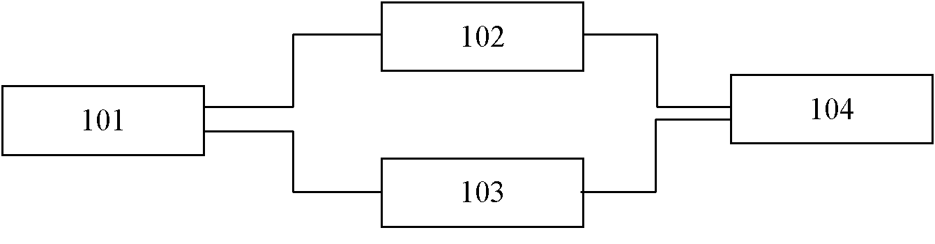
一种中央空调系统整体优化控制装置,所述装置包括电脑主机、弱电控制系统、强电控制系统,其中弱电控制系统和强电控制系统均通过RS485通讯接口并联连接至电脑主机。An overall optimization control device for a central air-conditioning system. The device includes a computer host, a weak current control system, and a strong current control system, wherein the weak current control system and the heavy current control system are connected in parallel to the computer host through an RS485 communication interface.
上述的中央空调系统整体优化控制装置中,弱电控制系统包括冷水机组控制系统、冷冻泵组控制系统、冷却泵组控制系统、冷却塔组控制系统、电动阀组控制系统,其中冷水机组控制系统、冷冻泵组控制系统、冷却泵组控制系统、冷却塔组控制系统、电动阀组控制系统均通过RS485通讯接口并联连接至电脑主机。In the overall optimization control device of the central air-conditioning system mentioned above, the weak current control system includes the chiller control system, the refrigeration pump control system, the cooling pump control system, the cooling tower control system, and the electric valve control system, among which the chiller control system, The refrigeration pump group control system, cooling pump group control system, cooling tower group control system, and electric valve group control system are all connected in parallel to the host computer through the RS485 communication interface.
上述的中央空调系统整体优化控制装置中,冷水机组控制系统的实现的是一种机组群控与随空调负荷变化动态调整冷水出水温度相结合的控制模式,冷水机组控制系统包括温湿度传感器、第一温度传感器组、第一模拟量输入模块组、第一电量传感器组、第一交流中间继电器组、第一数字量输入模块组、第一直流中间继电器组和第一数字量输出模块组,其中第一温度传感器组、温湿度传感器、第一电量传感器组经屏蔽双绞线并联连接至第一模拟量输入模块组,第一交流中间继电器组经220VAC电缆连接至第一数字量输入模块组,第一直流中间继电器组经24VDC电缆连接至第一数字量输出模块组,第一模拟量输入模块组、第一数字量输入模块组、第一数字量输出模块组经RS485通讯接口并联连接至电脑主机。In the above-mentioned overall optimization control device of the central air-conditioning system, the chiller control system implements a control mode that combines group control with dynamic adjustment of the cold water outlet temperature as the air-conditioning load changes. The chiller control system includes temperature and humidity sensors, the first A temperature sensor group, a first analog input module group, a first power sensor group, a first AC intermediate relay group, a first digital input module group, a first DC intermediate relay group and a first digital output module group, Among them, the first temperature sensor group, temperature and humidity sensor, and the first power sensor group are connected in parallel to the first analog input module group through shielded twisted pairs, and the first AC intermediate relay group is connected to the first digital input module group through 220VAC cables , the first DC intermediate relay group is connected to the first digital output module group through a 24VDC cable, the first analog input module group, the first digital input module group, and the first digital output module group are connected in parallel through the RS485 communication interface to the host computer.
上述的中央空调系统整体优化控制装置中,所述的冷冻泵组控制系统实现的是一种“一变多定”变频或全部变频方式与泵组群控相结合的控制模式,控制信号包括冷冻供回水干管温差、冷冻供回水干管压差、空调负荷率,所述的冷冻泵组控制系统包括第一流量传感器组、第二温度传感器组、第二模拟量输入模块组、第一差压传感器、第二电量传感器组、第二交流中间继电器组、第二数字量输入模块组、第二直流中间继电器组和第二数字量输出模块组,其中第一流量传感器组、第二温度传感器组、第一差压传感器、第二电量传感器组经屏蔽双绞线并联连接至第二模拟量输入模块组,第二交流中间继电器组经220VAC电缆连接至第二数字量输入模块组,第二直流中间继电器组经24VDC电缆连接至第二数字量输出模块组; 第二模拟量输入模块组、第二数字量输入模块组、第二数字量输出模块组经RS485通讯接口并联连接至电脑主机。In the above-mentioned overall optimization control device of the central air-conditioning system, the control system of the refrigeration pump group realizes a control mode in which "one variable multi-fixed" frequency conversion or all frequency conversion methods are combined with pump group control, and the control signals include refrigeration The temperature difference of supply and return main pipes, the pressure difference of refrigerated water supply and return main pipes, and the load rate of air conditioners. The control system of the refrigeration pump group includes a first flow sensor group, a second temperature sensor group, a second analog input module group, a first pressure sensor, the second power sensor group, the second AC intermediate relay group, the second digital input module group, the second DC intermediate relay group and the second digital output module group, in which the first flow sensor group, the second temperature sensor group, the first differential pressure sensor, and the second power sensor group are connected in parallel to the second analog input module group through shielded twisted-pair wires, the second AC intermediate relay group is connected to the second digital input module group through 220VAC cables, and the second The DC intermediate relay group is connected to the second digital output module group through a 24VDC cable; the second analog input module group, the second digital input module group, and the second digital output module group are connected in parallel to the computer host through the RS485 communication interface.
上述的中央空调系统整体优化控制装置中,所述的冷却泵组控制系统实现的是一种“一变多定”变频或全部变频方式与泵组群控相结合的控制模式,控制信号包括冷却供回水干管温差、冷却供回水干管压差,所述的冷却泵组控制系统包括第三直流中间继电器组、第三数字量输出模块组、第三交流中间继电器组、第三数字量输入模块组、第三电量传感器组、第三温度传感器组、第三模拟量输入模块组、第二差压传感器和第二流量传感器,其中第三电量传感器组、第三温度传感器组、第二差压传感器、第二流量传感器经屏蔽双绞线并联连接至第三模拟量输入模块组,第三交流中间继电器组经220VAC电缆连接至第三数字量输入模块组,第三直流中间继电器组经24VDC电缆连接至第三数字量输出模块组,第三模拟量输入模块组、第三数字量输入模块组、第三数字量输出模块组经RS485通讯接口并联连接至电脑主机。In the above-mentioned overall optimization control device of the central air-conditioning system, the cooling pump group control system realizes a control mode in which "one variable multiple fixed" frequency conversion or all frequency conversion methods are combined with pump group control, and the control signals include cooling The temperature difference of the supply and return main pipes and the pressure difference of the cooling supply and return main pipes. The control system of the cooling pump group includes a third DC intermediate relay group, a third digital output module group, a third AC intermediate relay group, and a third digital input The module group, the third power sensor group, the third temperature sensor group, the third analog input module group, the second differential pressure sensor and the second flow sensor, wherein the third power sensor group, the third temperature sensor group, the second differential The pressure sensor and the second flow sensor are connected in parallel to the third analog input module group through a shielded twisted pair, the third AC intermediate relay group is connected to the third digital input module group through a 220VAC cable, and the third DC intermediate relay group is connected to the third digital input module group through a 24VDC The cable is connected to the third digital output module group, and the third analog input module group, the third digital input module group, and the third digital output module group are connected in parallel to the host computer via the RS485 communication interface.
上述的中央空调系统整体优化控制装置中,所述的冷却塔组控制系统是一种台数群控,控制信号包括冷却塔组出水温度。所述的冷却塔组控制系统包括第四直流中间继电器组、第四数字量输出模块组第四交流中间继电器组、第四数字量输入模块组、第四电量传感器组和第四模拟量输入模块组,其中第四电量传感器组经屏蔽双绞线并联连接至第四模拟量输入模块组,第四交流中间继电器组经220VAC电缆连接至第四数字量输入模块组,第四直流中间继电器组经24VAC电缆连接至第四数字量输出模块组,第四模拟量输入模块组、第四数字量输入模块组、第四数字量输出模块组经RS485通讯接口并联连接至电脑主机。In the above-mentioned overall optimization control device of the central air-conditioning system, the cooling tower group control system is a group control of the number of units, and the control signal includes the outlet water temperature of the cooling tower group. The cooling tower group control system includes a fourth DC intermediate relay group, a fourth digital output module group, a fourth AC intermediate relay group, a fourth digital input module group, a fourth electric quantity sensor group and a fourth analog input module group, in which the fourth power sensor group is connected in parallel to the fourth analog input module group through a shielded twisted pair, the fourth AC intermediate relay group is connected to the fourth digital input module group through a 220VAC cable, and the fourth DC intermediate relay group is connected to the fourth digital input module group through The 24VAC cable is connected to the fourth digital output module group, the fourth analog input module group, the fourth digital input module group, and the fourth digital output module group are connected in parallel to the host computer via the RS485 communication interface.
上述的中央空调系统整体优化控制装置中,所述的电动阀组控制系统为联动控制模式。所述的电动阀组控制系统包括第五交流中间继电器组、第五数字量输入模块组、第五直流中间继电器组和第五数字量输出模块组,其中第五交流中间继电器组经220VAC电缆连接至第五数字量输入模块组,第五直流中间继电器组经24VAC电缆连接至第五数字量输出模块组,第五数字量输入模块组、第五数字量输出模块组经RS485通讯接口并联连接至电脑主机。In the above-mentioned overall optimization control device for the central air-conditioning system, the electric valve group control system is in a linkage control mode. The electric valve group control system includes the fifth AC intermediate relay group, the fifth digital input module group, the fifth DC intermediate relay group and the fifth digital output module group, wherein the fifth AC intermediate relay group is connected by a 220VAC cable To the fifth digital input module group, the fifth DC intermediate relay group is connected to the fifth digital output module group through a 24VAC cable, the fifth digital input module group, and the fifth digital output module group are connected in parallel to the RS485 communication interface. host computer.
上述的中央空调系统整体优化控制装置中,所述强电控制系统包括冷冻泵组变频控制系统和冷却泵组变频控制系统,其中冷冻泵组变频控制系统、冷却泵组变频控制系统经RS485通讯接口并联连接至电脑主机。In the above-mentioned overall optimization control device of the central air-conditioning system, the strong current control system includes the frequency conversion control system of the refrigeration pump group and the frequency conversion control system of the cooling pump group, wherein the frequency conversion control system of the refrigeration pump group and the frequency conversion control system of the cooling pump group are connected through the RS485 communication interface. Parallel connection to the host computer.
上述的中央空调系统整体优化控制装置中,所述的冷冻泵组变频控制系统包括第一前滤波器、第一变频器、第一后滤波器、第一交流接触器组和第一温差控制器,其中第一前滤波器、第一变频器、第一后滤波器、第一交流接触器组经三相电缆串联连接,第一变频器、第一温差控制器经屏蔽双绞线串联连接,第一变频器、第一温差控制器经RS485通讯接口并联连接至电脑主机;所述的冷却泵组变频控制系统包括第二交流接触器组、第二后滤波器、第二变频器、第二温差控制器和第二前滤波器,其中第二交流接触器组、第二后滤波器、第二变频器、第二前滤波器经三相电缆串联连接,第二变频器、第二温差控制器经屏蔽双绞线串联连接,第二变频器、第二温差控制器经RS485通讯接口并联连接至电脑主机。In the above-mentioned overall optimization control device for the central air-conditioning system, the frequency conversion control system of the refrigerating pump unit includes a first pre-filter, a first frequency converter, a first post-filter, a first AC contactor group and a first temperature difference controller , wherein the first pre-filter, the first frequency converter, the first post-filter, and the first AC contactor group are connected in series through a three-phase cable, the first frequency converter and the first temperature difference controller are connected in series through a shielded twisted pair, The first frequency converter and the first temperature difference controller are connected in parallel to the host computer via the RS485 communication interface; the cooling pump group frequency conversion control system includes a second AC contactor group, a second post-filter, a second frequency converter, a second The temperature difference controller and the second pre-filter, wherein the second AC contactor group, the second post-filter, the second frequency converter, and the second pre-filter are connected in series through a three-phase cable, the second frequency converter, the second temperature difference control The controllers are connected in series through a shielded twisted pair, and the second frequency converter and the second temperature difference controller are connected in parallel to the host computer through an RS485 communication interface.
本发明的工作原理:冷水机组有一个效率较高的负荷率范围,通过电脑对冷水机组运程群控,及时调整冷水机组的负荷率分布情况,使各冷水机组处于最佳效率运行状态,节约能耗、降低运行成本;同时为了保证冷水机组安全运行,对冷冻水和冷却水都有一个下限流量限制;当负荷率低、冷水机组启动台数多时,为了保证冷水机组的安全,冷冻水量和冷却水量均较大,此时通过对冷水机组的运程群控,减少冷水机组的启动台数,可以有效减小冷冻水泵和冷却水泵的水量需求,降低水泵能耗;每台冷水机组的冷冻和冷却水路的电动阀,应跟随冷水的启动而启动、停止而停止。如果冷水机组已经停止运行,而其冷冻和冷却水路的电动阀未关闭,将造成冷水机组侧大量冷冻水和冷却水的旁通,增加了水泵的无效能耗。通过对电动水阀的运程控制,能有效杜绝这部分无效能耗。The working principle of the present invention: the chiller has a high-efficiency load rate range, through the computer group control of the chiller range, adjust the load rate distribution of the chiller in time, so that each chiller is in the best efficient operating state, saving energy consumption and reduce operating costs; at the same time, in order to ensure the safe operation of the chiller, there is a lower flow limit for both chilled water and cooling water; when the load rate is low and the number of chillers started is large, in order to ensure the safety of the chiller Both are relatively large. At this time, through the group control of the chiller, reducing the number of chillers to start, can effectively reduce the water demand of the chilled water pump and the cooling water pump, and reduce the energy consumption of the pump; the freezing and cooling water of each chiller The electric valve should start and stop following the start of cold water. If the chiller has stopped running, but the electric valve of its freezing and cooling water circuit is not closed, it will cause a large amount of chilled water and cooling water to bypass on the side of the chiller, increasing the ineffective energy consumption of the water pump. Through the travel control of the electric water valve, this part of ineffective energy consumption can be effectively eliminated.
带旁通阀的冷冻水系统401,当空调冷水流量需求低于1台水泵额定流量时1台泵变频的群控方式能耗最低、节能最大;空调水流量需求介于1台与2台水泵额定流量之间时,2台水泵变频的群控方式能耗最低、节能最大;空调水流量需求介于2台与3台水泵额定流量之间时,3台水泵变频的群控方式能耗最低、节能最大;空调水流量需求介于3台与4台水泵额定流量之间时,4台水泵变频的群控方式能耗最低、节能最大;随着旁通压差设定值的增大,高负荷率时4种水泵变频群控方式之间的能耗差距减小。同时“多变多定”变频方式并不会引起工频水泵能耗的剧烈变化。因此,冷冻水泵的变频控制应根据空调负荷率、负荷时间分布设置不同的变频分布区间,合理安排变频水泵的运行台数,最大限度降低水泵能耗,节约运行费用。Chilled
与现有技术相比,本发明的有益效果是:所述一种中央空调系统整体优化控制装置可操作性强,可实现本地控制和远程控制的切换,远程控制操作灵活,有手动和自动两种运行模式,在远程自动控制模式下时时协调中央空调各设备的运行参数,寻找最佳控制策略,实现对中央空调各设备的最优控制,保证中央空调系统运行的安全性、稳定性和节能性。通过对冷水机组的远程智能控制,及时调整冷水机组的负荷率分布,使各冷水机组处于最佳效率运行状态,节约能耗、降低运行成本;减少冷水机组的启动台数,可以有效减小冷冻水泵和冷却水泵的水量需求,降低水泵能耗对主机运行时间自动记录,实现多机组的集中群控;最优冷冻水出水温度计算与控制;采用一台水泵变频和多台工频组合运行方式的运行效果比全部采用变频方式的投资少、运行稳定。冷却水泵的变频实现冷却水量的无级调节,配合冷却塔的台数控制,既能保证冷却水系统403的节能效果,也能保证系统的稳定运行,还能有效降低初投资;对运行数据存储,提供历史数据查询与趋势显示及打印报表。Compared with the prior art, the beneficial effect of the present invention is that the overall optimization control device of the central air-conditioning system has strong operability, can realize switching between local control and remote control, the remote control is flexible in operation, and has manual and automatic functions. In the remote automatic control mode, coordinate the operating parameters of the central air-conditioning equipment from time to time, find the best control strategy, realize the optimal control of the central air-conditioning equipment, and ensure the safety, stability and energy saving of the central air-conditioning system. sex. Through the remote intelligent control of the chillers, the load rate distribution of the chillers is adjusted in time, so that each chiller is in the best efficient operating state, saving energy and reducing operating costs; reducing the number of chillers to start can effectively reduce the chilled water pump and the water demand of the cooling water pump, reduce the energy consumption of the pump and automatically record the running time of the main engine, realize the centralized group control of multiple units; calculate and control the optimal chilled water outlet temperature; adopt the combination operation mode of one water pump frequency conversion and multiple power frequency The operation effect is less than the investment of all frequency conversion methods, and the operation is stable. The frequency conversion of the cooling water pump realizes the stepless adjustment of the cooling water volume. Cooperating with the number control of the cooling tower, it can not only ensure the energy saving effect of the
附图说明Description of drawings
图1是本发明的一种中央空调系统整体优化控制装置的监控结构图。Fig. 1 is a monitoring structure diagram of a central air-conditioning system overall optimization control device of the present invention.
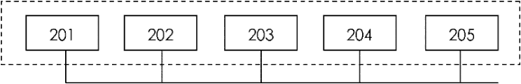
图2是本发明的弱电控制系统的结构图。Fig. 2 is a structural diagram of the weak current control system of the present invention.
图3是本发明的强电控制系统的结构图。Fig. 3 is a structural diagram of the heavy current control system of the present invention.
图4是中央空调设备结构图。Figure 4 is a structural diagram of the central air-conditioning equipment.
图5 是本发明的中央空调系统整体优化控制装置中央空调设备的连接图。Fig. 5 is a connection diagram of the central air-conditioning equipment of the central air-conditioning system overall optimization control device of the present invention.
图6是本发明的控制系统的逻辑结构图。Fig. 6 is a logical structure diagram of the control system of the present invention.
图7 是带旁通阀的变流量冷水系统在80kPa设定压差下的变频效果比较图。Figure 7 is a comparison diagram of the frequency conversion effect of the variable flow cold water system with a bypass valve under the set pressure difference of 80kPa.
图8是带旁通阀的变流量冷水系统在128kPa设定压差下的变频效果比较图。Figure 8 is a comparison diagram of the frequency conversion effect of the variable flow cold water system with a bypass valve under the set pressure difference of 128kPa.
图9 是带旁通阀的变流量冷水系统在170kPa设定压差下的变频效果比较图。Figure 9 is a comparison diagram of the frequency conversion effect of the variable flow cold water system with a bypass valve under the set pressure difference of 170kPa.
图10是水泵单台变频多台工频运行时功率对比图。Figure 10 is a power comparison diagram of a single pump with frequency conversion and multiple power frequency operation.
具体实施方式Detailed ways
以下结合附图对本发明的实施作进一步说明,但本发明的实施和保护范围不限于此。The implementation of the present invention will be further described below in conjunction with the accompanying drawings, but the implementation and protection scope of the present invention are not limited thereto.
本发明的特点是控制系统溶入了中央空调系统运行特性物理数学模型、人工智能和实际运行经验修正等思想,由计算机工作站后台程序实时运行物理数学模型自动寻优,以获取不同负荷、不同室外环境等条件下空调系统最优运行工况,根据现场调试结果和实际运行经验对计算结果进行修订以提高控制准确性,人工智能在对空调区域的负荷预测以及控制系统寻优求解中起到关键性作用。The feature of the present invention is that the control system incorporates ideas such as the physical and mathematical model of the operating characteristics of the central air-conditioning system, artificial intelligence and actual operating experience correction, and the background program of the computer workstation runs the physical and mathematical model in real time to automatically optimize to obtain different loads and different outdoor loads. The optimal operating conditions of the air-conditioning system under environmental and other conditions. According to the on-site debugging results and actual operating experience, the calculation results are revised to improve the control accuracy. Artificial intelligence plays a key role in the load forecasting of the air-conditioning area and the optimization of the control system. sexual effect.
如图4,中央空调系统整体优化控制装置中所述的中央空调设备包括冷冻水系统401、冷水机组402和冷却水系统403。冷冻水系统401由冷冻水供回水管、冷冻水电动阀512、旁通调节系统511和冷冻泵组513构成。冷却水系统403由冷却水供回水管、冷却水电动阀402、冷却塔进水电动516阀、冷却塔出水电动阀517、冷却塔组519和冷却泵组514构成。As shown in FIG. 4 , the central air-conditioning equipment described in the overall optimization control device of the central air-conditioning system includes a
如图1,一种中央空调系统整体优化控制装置包括电脑主机101、弱电控制系统102、强电控制系统103,其中弱电控制系统102和强电控制系统103均通过RS485通讯接口并联连接至101。As shown in Figure 1, a central air-conditioning system overall optimization control device includes a
如图2,弱电控制系统102包括冷水机组控制系统201、冷冻泵组控制系统202、冷却泵组控制系统203、冷却塔组控制系统204、电动阀组控制系统205,其中冷水机组控制系统201、冷冻泵组控制系统202、冷却泵组控制系统203、冷却塔组控制系统204、电动阀组控制系统205均通过RS485通讯接口并联连接至电脑主机101。As shown in Figure 2, the weak
如图5所示,冷水机组控制系统201包括温湿度传感器528、第一温度传感器组529、第一模拟量输入模块组530、第一电量传感器组531、第一交流中间继电器组532、第一数字量输入模块组533、第一直流中间继电器组534和第一数字量输出模块组535,其中第一温度传感器组529、温湿度传感器528、第一电量传感器组531经屏蔽双绞线并联连接至第一模拟量输入模块组530,第一交流中间继电器组532经220VAC电缆连接至第一数字量输入模块组533,第一直流中间继电器组534经24VDC电缆连接至第一数字量输出模块组535,第一模拟量输入模块组530、第一数字量输入模块组533、第一数字量输出模块组535经RS485通讯接口并联连接至电脑主机101。所述的冷冻泵组控制系统202包括第一流量传感器组519、第二温度传感器组520、第二模拟量输入模块组521、第一差压传感器522、第二电量传感器组523、第二交流中间继电器组524、第二数字量输入模块组525、第二直流中间继电器组526和第二数字量输出模块组527,其中第一流量传感器组519、第二温度传感器组520、第一差压传感器522、第二电量传感器组523经屏蔽双绞线并联连接至第二模拟量输入模块组521,第二交流中间继电器组524经220VAC电缆连接至第二数字量输入模块组525,第二直流中间继电器组526经24VDC电缆连接至第二数字量输出模块组527; 第二模拟量输入模块组521、第二数字量输入模块组525、第二数字量输出模块组527经RS485通讯接口并联连接至电脑主机101。所述的冷却泵组控制系统203包括第三直流中间继电器组536、第三数字量输出模块组537、第三交流中间继电器组538、第三数字量输入模块组539、第三电量传感器组540、第三温度传感器组541、第三模拟量输入模块组542、第二差压传感器543和第二流量传感器544,其中第三电量传感器组540、第三温度传感器组541、第二差压传感器543、第二流量传感器544经屏蔽双绞线并联连接至第三模拟量输入模块组542,第三交流中间继电器组538经220VAC电缆连接至第三数字量输入模块组539,第三直流中间继电器组536经24VDC电缆连接至第三数字量输出模块组537,第三模拟量输入模块组542、第三数字量输入模块组539、第三数字量输出模块组537经RS485通讯接口并联连接至电脑主机101。所述的冷却塔组控制系统204包括第四直流中间继电器组545、第四数字量输出模块组546第四交流中间继电器组547、第四数字量输入模块组548、第四电量传感器组549和第四模拟量输入模块组550,其中第四电量传感器组549经屏蔽双绞线并联连接至第四模拟量输入模块组550,第四交流中间继电器组547经220VAC电缆连接至第四数字量输入模块组548,第四直流中间继电器组545经24VAC电缆连接至第四数字量输出模块组546,第四模拟量输入模块组550、第四数字量输入模块组548、第四数字量输出模块组546经RS485通讯接口并联连接至电脑主机101。所述的电动阀组控制系统205包括第五交流中间继电器组553、第五数字量输入模块组554、第五直流中间继电器组551和第五数字量输出模块组552,其中第五交流中间继电器组553经220VAC电缆连接至第五数字量输入模块组554,第五直流中间继电器组551经24VAC电缆连接至第五数字量输出模块组552,第五数字量输入模块组554、第五数字量输出模块组552经RS485通讯接口并联连接至电脑主机101。As shown in Figure 5, the
如图3,所述强电控制系统103包括冷冻泵组变频控制系统301和冷却泵组变频控制系统302,其中冷冻泵组变频控制系统301、冷却泵组变频控制系统302经RS485通讯接口并联连接至电脑主机101。如图5,所述的冷冻泵组变频控制系统301包括第一前滤波器501、第一变频器502、第一后滤波器504、第一交流接触器组505和第一温差控制器503,其中第一前滤波器501、第一变频器502、第一后滤波器504、第一交流接触器组505经三相电缆串联连接,第一变频器502、第一温差控制器503经屏蔽双绞线串联连接,第一变频器502、第一温差控制器503经RS485通讯接口并联连接至电脑主机101;所述的冷却泵组变频控制系统302包括第二交流接触器组506、第二后滤波器507、第二变频器508、第二温差控制器509和第二前滤波器510,其中第二交流接触器组506、第二后滤波器507、第二变频器508、第二前滤波器510经三相电缆串联连接,第二变频器508、第二温差控制器509经屏蔽双绞线串联连接,第二变频器508、第二温差控制器509经RS485通讯接口并联连接至电脑主机101。As shown in Figure 3, the strong
上述各传感器采集各设备运行的物理参数并将其转化为标准电压、电流信号,所述第一温差控制器503采集冷水供、回水干管温差参数,经PID计算后输出标准电压、电流至第一变频器502,调整变频冷水泵的运行频率参数,第二温差控制器509采集冷却供、回水干管温差参数,经PID计算后输出标准电压、电流至第二变频器502,调整变频冷却泵的运行频率参数,同时电脑主机101在远程控制模式时可设定第一温差控制器503、第二温差控制器509的控制温差。温湿度传感器528采集室外温湿度参数,第一电量传感器组531采集各冷水机耗电参数,第一温度传感器组529采集各冷水机的冷冻进、出水温度参数和冷却进、出水温度参数,第二电量传感器组524采集各冷水泵耗电参数,第二温度传感器组521采集冷水供、回水干管温度参数,第一流量传感器组520采集冷水干管水流量参数,第一差压传感器522采集冷水供、回水干管差压参数,第三电量传感器组540采集冷却水泵耗电参数,第三温度传感器组541采集冷却水供、回水干管温度参数,第二差压传感器543采集冷却水供、回水干管差压参数,由第四电量传感器组549采集各冷却塔耗电参数。The above-mentioned sensors collect the physical parameters of each equipment operation and convert them into standard voltage and current signals. The first
上述各输入模块组采集各传感器的标准电压、电流参数,经RS485通讯接口输入至电脑主机101,各模拟量输入模块组采集各系统设备的运行状态参数,经RS485通讯接口输入至电脑主机101,电脑主机根据所述各传感器获取的运行参数信息,对用户侧冷负荷进行时时动态分析预测,根据各数字量输入模块组获取的设备运行状态信息,监控中央空调系统各设备的运行状况和运行时间,最后经电脑主机101的后台逻辑计算分析,通过数字量输出模块组控制强电控制系统103,进而控制中央空调系统的最佳运行。Each of the above-mentioned input module groups collects the standard voltage and current parameters of each sensor, and inputs them to the
本实施方式中,温湿度传感器为两线制4~20mA电流输出。由24VDC电源供电。各电量传感器组均为两线制4~20mA电流输出,具体量程根据中央空调设备而定,由24VDC电源供电。各温度传感器组均为两线制4~20mA电流输出,精度±1%,量程为0~50℃,具体尺寸根据中央空调设备而定,由24VDC电源供电。各流量传感器组均为两线制4~20mA电流输出,具体量程及尺寸根据中央空调设备而定,由24VDC电源供电。各差压传感器组均为两线制4~20mA电流输出,具体量程及尺寸根据中央空调设备而定,由DC24V电源供电。各交流中间继电器组均为220VAC中间继电器。各直流中间继电器组均为24VDC中间继电器。In this embodiment, the temperature and humidity sensor is a two-wire 4-20mA current output. Powered by 24VDC power supply. Each power sensor group is a two-wire 4 ~ 20mA current output, the specific range depends on the central air-conditioning equipment, powered by 24VDC power supply. Each temperature sensor group is a two-wire 4~20mA current output, with an accuracy of ±1%, and a range of 0~50°C. The specific size depends on the central air-conditioning equipment, and it is powered by a 24VDC power supply. Each flow sensor group is a two-wire 4-20mA current output, the specific range and size are determined according to the central air-conditioning equipment, powered by 24VDC power supply. Each differential pressure sensor group is a two-wire 4-20mA current output, the specific range and size are determined according to the central air-conditioning equipment, powered by DC24V power supply. Each AC intermediate relay group is a 220VAC intermediate relay. Each DC intermediate relay group is a 24VDC intermediate relay.
以下再结合附图6~10和相关控制模式对上述中央空调系统整体优化控制装置的实施进行说明。The implementation of the above-mentioned overall optimization control device for the central air-conditioning system will be described below in conjunction with FIGS. 6-10 and related control modes.
中央空调系统整体优化控制装置中,本地控制和远程控制互锁,当为本地控制时,在本地操作系统,实现对中央空调设备104的控制,中央空调设备104的运行状况反馈到及电脑主机101;当为远程控制时,电脑主机101通过弱电控制系统102系统及强电控制系统103,控制中央空调设备104,中央空调设备104的运行参数反馈到电脑主机101。远程控制又分为手动控制模式和自动控制模式,手动控制模式为操作员直接通过操作电脑主机101,通过弱电控制系统102系统及强电控制系统103实现对中央空调设备104的控制;自动控制模式为电脑主机101通过弱电控制系统102及强电控制系统103监控中央空调设备104,并根据采集得的中央空调设备104运行参数进行运算,自动调节中央空调设备104的启停、水泵频率控制及加载和卸载。如图6所示控制系统的逻辑结构,对冷水机组402采用台数群控和出水温度控制策略,对冷冻泵组513和冷却泵组514采用台数控制和单台变频控制策略,对冷却塔组519采用台数群控和出水温度控制策略,根据中央空调设备104的运行参数协调控制。In the overall optimization control device of the central air-conditioning system, the local control and remote control are interlocked. When it is local control, the local operating system realizes the control of the central air-
各传感器采集中央空调设备104运行的物理参数并将其转化为标准电压、电流信号,其中温湿度传感器528采集室外温湿度参数;第一电量传感器531组采集各冷水机耗电参数;第一温度传感器组529采集各冷水机的冷冻进、出水温度参数和冷却进、出水温度参数;第二电量传感器组524采集各冷水泵耗电参数;第二温度传感器组521采集冷水供、回水干管温度参数;第一流量传感器组520采集冷冻水干管水流量参数;第一差压传感器522采集冷水供、回水干管差压参数;第三电量传感器组540采集冷却水泵耗电参数;第三温度传感器组541采集冷却水供、回水干管温度参数;第二差压传感器543采集冷却水供、回水干管差压参数;由第四电量传感器组549采集各冷却塔耗电参数。Each sensor collects the physical parameters of the operation of the central air-
第一温差控制器503采集冷水供、回水干管温差参数,经PID计算后输出标准电压、电流至第一变频器502,调整变频冷水泵的运行频率参数;第二温差控制器采集冷却供、回水干管温差参数,经PID计算后输出标准电压、电流至第二变频器,调整变频冷却泵的运行频率参数。同时电脑主机101在远程控制模式时可设定第一温差控制器503、第二温差控制器的控制温差。The first
对冷水机组冷冻水进出水温度、冷却水进出水温度、主机功率、主机负荷率、单台运行时间等主要参数的监控,具有PC接口的机组,可通过其数据通讯协议直接获取机组运行各参数,并实现远程控制;没有PC接口或未知设备数据通讯协议,则通过温度传感器、功率传感器等变送元件实现各监测参数的模拟量化,并由数据采集卡或数据采集模块将其转换为数字信号,通过数据网络与工作站计算机实现数据通讯。利用采集到的数据进行分析、处理,自动计算分析机组负荷率、制冷量,根据室外环境、负荷率、围护结构及用户工作特性等优化启动冷水机组。在远程自动控制模式时,操作员可在人工控制模式下设定不同冷水机组不同时段的冷冻水出口温度及进出口温差,控制冷水机组的开启,也可在智能控制模式下由电脑主机101自动寻优,选择不同冷水机组的最佳冷冻水出水温度和进出水温差,并根据不同的负荷区间调节冷水机组运行台数,确定最优节能运行和管理方案,实现冷水机组在不同负荷区间的最优组合。Monitoring of main parameters such as chilled water inlet and outlet temperature, cooling water inlet and outlet temperature, main engine power, main engine load rate, single running time and other main parameters of the chiller. The unit with PC interface can directly obtain the operating parameters of the unit through its data communication protocol , and realize remote control; if there is no PC interface or unknown device data communication protocol, the analog quantification of each monitoring parameter is realized through temperature sensor, power sensor and other transmission components, and it is converted into digital signal by data acquisition card or data acquisition module , Realize data communication with the workstation computer through the data network. Use the collected data for analysis and processing, automatically calculate and analyze the load rate and cooling capacity of the unit, and optimize the start-up of the chiller according to the outdoor environment, load rate, enclosure structure and user operating characteristics. In the remote automatic control mode, the operator can set the chilled water outlet temperature and the temperature difference between the inlet and outlet of different chillers at different periods in the manual control mode, and control the opening of the chiller, or it can be automatically controlled by the
对冷冻水系统401的供回水温度、供回水压差、冷冻水流量、旁通流量、冷冻泵功率、冷冻泵单台运行时间等主要参数进行监控,根据室外空气温湿度、室内空调负荷以及主机的运行情况,电脑主机101实时计算最低能耗条件下实际所需最小流量,然后对冷冻水泵变频器进行远程控制,采用温差控制、压差控制、温差压差混合控制三种变频方式。在远程自动控制模式时,操作员可在人工控制模式下设定不同冷水机组不同时段的冷冻水进出口温差及压差,选用压差控制或温差控制模式,也可在智能控制模式下由电脑主机101自动寻优,选用温差控制、压差控制或温差压差混合控制,时时选择最佳控制温差或压差,采用PID加控制时间控制水泵的运行频率,对水泵进行单台水泵变频多台工频控制及台数控制;在本地控制模式时,操作员可在温差控制器上设置冷冻水供回水温差,采用PID控制水泵的运行频率,电脑主机101监控本地冷冻水泵组运行。Monitor the main parameters of the
对冷却水系统403的供回水温度、供回水压差、冷却水流量、冷却泵功率、冷却泵单台运行时间等主要参数进行监控,根据室外空气温湿度、室内空调负荷以及主机的运行情况,电脑主机101实时计算最低能耗条件下实际所需最小流量,然后对冷却水泵变频器进行远程控制,采用温差控制和压差控制两种变频方式。在远程自动控制模式时,操作员可在人工控制模式下设定不同冷水机组不同时段的冷冻水进出口温差及压差,选用压差控制或温差控制模式,也可在智能控制模式下由电脑主机101自动寻优,选用温差控制或压差控制,实时选择最佳控制温差或压差,采用PID加控制时间控制水泵的运行频率,对水泵进行单台水泵变频多台工频控制及台数控制;在本地控制模式时,操作员可在温差控制器上设置冷冻水供回水温差,采用PID控制水泵的运行频率,电脑主机101监控本地冷却水泵组运行。Monitor the main parameters of the cooling
如图7-图9不同供回水设定压差下的变频效果比较,当水流量较低时(小于100m3/h),采用1台水泵变频的能耗最低;随着水流量的增大(100m3/h-200m3/h),采用2台水泵变频的能耗最低;随着水流量的增大(200m3/h-300m3/h),采用3台水泵变频的能耗最低;随着水流量的增大(大于300m3/h),采用4台水泵变频的能耗最低;同时采用4台水泵工频运行的能耗最高。水泵的变流量运行不仅仅是单纯的变频调节,还应根据系统参数协调优化水泵控制。As shown in Figure 7-9, the comparison of the frequency conversion effect under different set pressure differences of supply and return water, when the water flow is low (less than 100m 3 /h), the energy consumption of frequency conversion with one water pump is the lowest; with the increase of water flow Large (100m 3 /h-200m 3 /h), the energy consumption of 2 pumps with frequency conversion is the lowest; with the increase of water flow (200m 3 /h-300m 3 /h), the energy consumption of 3 water pumps with frequency conversion The lowest; with the increase of water flow (greater than 300m 3 /h), the energy consumption of 4 water pumps with frequency conversion is the lowest; while the energy consumption of 4 water pumps with power frequency operation is the highest. The variable flow operation of the water pump is not only a simple frequency conversion adjustment, but also coordinates and optimizes the water pump control according to the system parameters.
如图10水泵单台变频多台工频并联运行时功率对比,当工频运行的水泵于变频运行的水泵并联运行时,变频泵的运行对工频泵的运行基本上不产生影响。变频泵和工频泵并联运行是可行的,系统可安全稳定运行且节约了的成本。As shown in Figure 10, the power comparison of a single pump with frequency conversion and multiple power frequency parallel operation, when the water pump running at power frequency is running in parallel with the pump running at frequency conversion, the operation of the frequency conversion pump basically has no impact on the operation of the power frequency pump. Parallel operation of variable frequency pumps and power frequency pumps is feasible, the system can run safely and stably and save costs.
对冷却塔组518的功率、单台运行时间、冷却水供回水温差等主要参数的监控根据室外空气温湿度、室内空调负荷以及主机的运行情况,电脑主机101对冷却塔组518实现台数群控。Monitoring of main parameters such as the power of the
可见,本发明可操作性强,可实现对中央空调各设备的最优控制,保证中央空调系统运行的安全性、稳定性和节能性。通过对冷水机组的远程智能控制,及时调整冷水机组的负荷率分布,使各冷水机组处于最佳效率运行状态,节约能耗、降低运行成本。It can be seen that the present invention has strong operability, can realize optimal control of various equipment of the central air conditioner, and ensure the safety, stability and energy saving of the central air conditioner system. Through the remote intelligent control of the chiller, the load rate distribution of the chiller is adjusted in time, so that each chiller is in the best efficient operation state, saving energy consumption and reducing operating costs.
Claims (10)
Priority Applications (1)
| Application Number | Priority Date | Filing Date | Title |
|---|---|---|---|
| CN 201110085602 CN102135311B (en) | 2011-04-06 | 2011-04-06 | Air conditioning system integral optimized control device |
Applications Claiming Priority (1)
| Application Number | Priority Date | Filing Date | Title |
|---|---|---|---|
| CN 201110085602 CN102135311B (en) | 2011-04-06 | 2011-04-06 | Air conditioning system integral optimized control device |
Publications (2)
| Publication Number | Publication Date |
|---|---|
| CN102135311A true CN102135311A (en) | 2011-07-27 |
| CN102135311B CN102135311B (en) | 2013-05-08 |
Family
ID=44295170
Family Applications (1)
| Application Number | Title | Priority Date | Filing Date |
|---|---|---|---|
| CN 201110085602 Expired - Fee Related CN102135311B (en) | 2011-04-06 | 2011-04-06 | Air conditioning system integral optimized control device |
Country Status (1)
| Country | Link |
|---|---|
| CN (1) | CN102135311B (en) |
Cited By (20)
| Publication number | Priority date | Publication date | Assignee | Title |
|---|---|---|---|---|
| CN102980272A (en) * | 2012-12-08 | 2013-03-20 | 珠海派诺科技股份有限公司 | Air conditioner system energy saving optimization method based on load prediction |
| CN103776132A (en) * | 2014-02-13 | 2014-05-07 | 天津市聚晶自动化新技术有限公司 | Energy-saving control system of central air conditioner |
| CN104390323A (en) * | 2014-12-08 | 2015-03-04 | 中国建筑设计咨询有限公司 | Electric temperature difference control valve of air-conditioning system and temperature difference control method of electric temperature difference control valve |
| CN104566844A (en) * | 2013-10-18 | 2015-04-29 | 宁夏先锋软件有限公司 | Central air conditioner energy-saving unit |
| CN105222354A (en) * | 2014-07-01 | 2016-01-06 | 珠海格力电器股份有限公司 | Control method and device, control chip and water heater |
| CN105243179A (en) * | 2015-09-01 | 2016-01-13 | 湖南集森节能环保科技有限公司 | Method for determining optimal operational number of variable-frequency pump units and method for controlling increment or reduction of number of variable-frequency pump units |
| CN105444356A (en) * | 2015-12-08 | 2016-03-30 | 刘俊声 | Intelligent energy efficiency optimizing control system for central air conditioning system and control method of intelligent energy efficiency optimizing control system |
| CN105636266A (en) * | 2016-01-19 | 2016-06-01 | 河南海林自控设备有限公司 | Energy-saving monitoring system for civil air defense |
| CN106196512A (en) * | 2016-08-25 | 2016-12-07 | 珠海格力电器股份有限公司 | Control system for cold station of central air conditioner |
| CN106765860A (en) * | 2015-11-25 | 2017-05-31 | 中广核工程有限公司 | A kind of control system and method for nuclear power station central air-conditioning |
| CN106979639A (en) * | 2016-01-15 | 2017-07-25 | 浙江理工大学 | The high-precision twin-stage temperature control method of great Rong water tanks |
| CN107238150A (en) * | 2017-06-28 | 2017-10-10 | 贵州绿云科技有限公司 | A kind of cold station system of the double low-temperature receivers of modularization |
| CN109240194A (en) * | 2018-09-21 | 2019-01-18 | 中持水务股份有限公司 | Electric machine control system and control method for engineering of water treatment |
| CN110470039A (en) * | 2019-09-06 | 2019-11-19 | 创新奇智(重庆)科技有限公司 | A kind of air conditioner water valve regulation method based on the theory of optimal control |
| CN112036077A (en) * | 2020-08-14 | 2020-12-04 | 天地(常州)自动化股份有限公司 | Overheating protection method for mining explosion-proof water-cooled frequency converter without flow sensor |
| CN113028603A (en) * | 2021-03-24 | 2021-06-25 | 贵州汇通华城股份有限公司 | Equipment monitoring system applied to central air-conditioning system |
| CN113719442A (en) * | 2021-09-14 | 2021-11-30 | 上海凯泉泵业(集团)有限公司 | High-efficient pump package system |
| CN113983729A (en) * | 2021-12-02 | 2022-01-28 | 博锐尚格科技股份有限公司 | Method and device for judging bypass operation of water chilling unit |
| CN114963414A (en) * | 2022-06-08 | 2022-08-30 | 山东润一智能科技有限公司 | Air conditioning system intelligent regulation and control device based on AI data analysis |
| CN115079559A (en) * | 2022-07-07 | 2022-09-20 | 核工业理化工程研究院 | A chiller remote switching control system and method thereof |
Citations (5)
| Publication number | Priority date | Publication date | Assignee | Title |
|---|---|---|---|---|
| CN2636141Y (en) * | 2003-06-13 | 2004-08-25 | 北京时代嘉华环境控制科技有限公司 | Energy saving controller for monitoring and controlling operation of circulation water system of central air conditioner |
| CN1598425A (en) * | 2004-07-20 | 2005-03-23 | 贵州华城楼宇科技有限公司 | Cold / worming water energy-saving apparatus of central air conditioner |
| CN2703223Y (en) * | 2003-08-29 | 2005-06-01 | 苏州利源自动化科技有限公司 | Central air conditioner energy-saving controlling device |
| CN101140096A (en) * | 2007-10-18 | 2008-03-12 | 苏州艾隆科技有限公司 | electricity economizer centralized management method and system of central air-conditioning |
| CN201973836U (en) * | 2011-04-06 | 2011-09-14 | 华南理工大学 | Integral optimization control device of central air-conditioning system |
-
2011
- 2011-04-06 CN CN 201110085602 patent/CN102135311B/en not_active Expired - Fee Related
Patent Citations (5)
| Publication number | Priority date | Publication date | Assignee | Title |
|---|---|---|---|---|
| CN2636141Y (en) * | 2003-06-13 | 2004-08-25 | 北京时代嘉华环境控制科技有限公司 | Energy saving controller for monitoring and controlling operation of circulation water system of central air conditioner |
| CN2703223Y (en) * | 2003-08-29 | 2005-06-01 | 苏州利源自动化科技有限公司 | Central air conditioner energy-saving controlling device |
| CN1598425A (en) * | 2004-07-20 | 2005-03-23 | 贵州华城楼宇科技有限公司 | Cold / worming water energy-saving apparatus of central air conditioner |
| CN101140096A (en) * | 2007-10-18 | 2008-03-12 | 苏州艾隆科技有限公司 | electricity economizer centralized management method and system of central air-conditioning |
| CN201973836U (en) * | 2011-04-06 | 2011-09-14 | 华南理工大学 | Integral optimization control device of central air-conditioning system |
Cited By (28)
| Publication number | Priority date | Publication date | Assignee | Title |
|---|---|---|---|---|
| CN102980272B (en) * | 2012-12-08 | 2014-12-03 | 珠海派诺科技股份有限公司 | Air conditioner system energy saving optimization method based on load prediction |
| CN102980272A (en) * | 2012-12-08 | 2013-03-20 | 珠海派诺科技股份有限公司 | Air conditioner system energy saving optimization method based on load prediction |
| CN104566844A (en) * | 2013-10-18 | 2015-04-29 | 宁夏先锋软件有限公司 | Central air conditioner energy-saving unit |
| CN103776132A (en) * | 2014-02-13 | 2014-05-07 | 天津市聚晶自动化新技术有限公司 | Energy-saving control system of central air conditioner |
| CN103776132B (en) * | 2014-02-13 | 2016-08-17 | 天津市聚晶自动化新技术有限公司 | A kind of controlling system of central air conditioner |
| CN105222354A (en) * | 2014-07-01 | 2016-01-06 | 珠海格力电器股份有限公司 | Control method and device, control chip and water heater |
| CN105222354B (en) * | 2014-07-01 | 2018-07-03 | 珠海格力电器股份有限公司 | Control method and device, control chip and water heater |
| CN104390323B (en) * | 2014-12-08 | 2017-02-22 | 中国建筑设计咨询有限公司 | Electric temperature difference control valve of air-conditioning system and temperature difference control method of electric temperature difference control valve |
| CN104390323A (en) * | 2014-12-08 | 2015-03-04 | 中国建筑设计咨询有限公司 | Electric temperature difference control valve of air-conditioning system and temperature difference control method of electric temperature difference control valve |
| CN105243179A (en) * | 2015-09-01 | 2016-01-13 | 湖南集森节能环保科技有限公司 | Method for determining optimal operational number of variable-frequency pump units and method for controlling increment or reduction of number of variable-frequency pump units |
| CN106765860A (en) * | 2015-11-25 | 2017-05-31 | 中广核工程有限公司 | A kind of control system and method for nuclear power station central air-conditioning |
| CN105444356A (en) * | 2015-12-08 | 2016-03-30 | 刘俊声 | Intelligent energy efficiency optimizing control system for central air conditioning system and control method of intelligent energy efficiency optimizing control system |
| CN105444356B (en) * | 2015-12-08 | 2018-12-11 | 刘俊声 | A kind of the efficiency Intelligent Optimal control system and its control method of central air conditioner system |
| CN106979639B (en) * | 2016-01-15 | 2019-11-15 | 浙江理工大学 | High-precision two-stage temperature control method for large-capacity water tanks |
| CN106979639A (en) * | 2016-01-15 | 2017-07-25 | 浙江理工大学 | The high-precision twin-stage temperature control method of great Rong water tanks |
| CN105636266A (en) * | 2016-01-19 | 2016-06-01 | 河南海林自控设备有限公司 | Energy-saving monitoring system for civil air defense |
| CN106196512A (en) * | 2016-08-25 | 2016-12-07 | 珠海格力电器股份有限公司 | Control system for cold station of central air conditioner |
| CN107238150A (en) * | 2017-06-28 | 2017-10-10 | 贵州绿云科技有限公司 | A kind of cold station system of the double low-temperature receivers of modularization |
| CN109240194A (en) * | 2018-09-21 | 2019-01-18 | 中持水务股份有限公司 | Electric machine control system and control method for engineering of water treatment |
| CN110470039A (en) * | 2019-09-06 | 2019-11-19 | 创新奇智(重庆)科技有限公司 | A kind of air conditioner water valve regulation method based on the theory of optimal control |
| CN112036077A (en) * | 2020-08-14 | 2020-12-04 | 天地(常州)自动化股份有限公司 | Overheating protection method for mining explosion-proof water-cooled frequency converter without flow sensor |
| CN112036077B (en) * | 2020-08-14 | 2023-10-24 | 天地(常州)自动化股份有限公司 | Overheat protection method for mining flameproof water-cooled frequency converter without flow sensor |
| CN113028603A (en) * | 2021-03-24 | 2021-06-25 | 贵州汇通华城股份有限公司 | Equipment monitoring system applied to central air-conditioning system |
| CN113719442A (en) * | 2021-09-14 | 2021-11-30 | 上海凯泉泵业(集团)有限公司 | High-efficient pump package system |
| CN113983729A (en) * | 2021-12-02 | 2022-01-28 | 博锐尚格科技股份有限公司 | Method and device for judging bypass operation of water chilling unit |
| CN114963414A (en) * | 2022-06-08 | 2022-08-30 | 山东润一智能科技有限公司 | Air conditioning system intelligent regulation and control device based on AI data analysis |
| CN114963414B (en) * | 2022-06-08 | 2023-11-24 | 山东润一智能科技有限公司 | Intelligent air conditioning system regulating and controlling device based on AI data analysis |
| CN115079559A (en) * | 2022-07-07 | 2022-09-20 | 核工业理化工程研究院 | A chiller remote switching control system and method thereof |
Also Published As
| Publication number | Publication date |
|---|---|
| CN102135311B (en) | 2013-05-08 |
Similar Documents
| Publication | Publication Date | Title |
|---|---|---|
| CN102135311B (en) | Air conditioning system integral optimized control device | |
| CN103277875B (en) | Energy-saving control system for refrigeration plant room | |
| CN105020845B (en) | A kind of air-conditioning system linkage energy-saving control system and method | |
| CN100487332C (en) | Energy-saving intelligent control system for central air conditioner | |
| CN205372917U (en) | Central air conditioning degree of depth energy -saving control system based on initiative optimizing | |
| CN101090335B (en) | Method and system for remote adjustment of indoor temperature and load of household air conditioner | |
| CN101216207B (en) | 26 degree central air-conditioning intelligent energy-saving management system | |
| CN105953353A (en) | Central air-conditioning cold source system quota control method and system | |
| CN102062459A (en) | Energy-saving control system of central air conditioner | |
| CN110848895B (en) | A kind of non-industrial air conditioner flexible load control method and system | |
| CN104818747B (en) | Town and country are for water integrated ductwork pressure Optimized Operation intelligence control system and using method | |
| CN104134100A (en) | Energy-saving management system based on cloud computing | |
| CN201973836U (en) | Integral optimization control device of central air-conditioning system | |
| CN102374605A (en) | Automatic optimizing energy-saving technology and system for central air-conditioning water system | |
| CN201129827Y (en) | A central air-conditioning control device | |
| CN108168043B (en) | Central air conditioning water system variable flow active energy saving automatic control system | |
| CN101922783A (en) | Enthalpy control-based method and system for controlling energy conservation of air conditioner | |
| CN214536620U (en) | Network architecture of air-conditioning and air-water coordination energy-saving control device of subway station | |
| CN204902127U (en) | Terminal coordinated control's of air conditioner water system and air conditioner economizer | |
| CN201547915U (en) | Central air-conditioning energy-saving device | |
| CN201059715Y (en) | A quality control system for central air-conditioning refrigeration station | |
| CN102882276B (en) | Energy efficiency monitoring method based on demand response | |
| CN2472116Y (en) | Fuzzy control energy saver for central air conditioner | |
| CN201292954Y (en) | Water pump and/or blower fan highly effective energy-conserving control system | |
| CN118729483A (en) | Energy-saving optimization control method for MIMO water-cooled air-conditioning system based on MPC |
Legal Events
| Date | Code | Title | Description |
|---|---|---|---|
| C06 | Publication | ||
| PB01 | Publication | ||
| C10 | Entry into substantive examination | ||
| SE01 | Entry into force of request for substantive examination | ||
| C14 | Grant of patent or utility model | ||
| GR01 | Patent grant | ||
| CF01 | Termination of patent right due to non-payment of annual fee |
Granted publication date: 20130508 Termination date: 20190406 |
|
| CF01 | Termination of patent right due to non-payment of annual fee |