CN102113367B - Wireless communication network analyzer - Google Patents
Wireless communication network analyzer Download PDFInfo
- Publication number
- CN102113367B CN102113367B CN2009801307989A CN200980130798A CN102113367B CN 102113367 B CN102113367 B CN 102113367B CN 2009801307989 A CN2009801307989 A CN 2009801307989A CN 200980130798 A CN200980130798 A CN 200980130798A CN 102113367 B CN102113367 B CN 102113367B
- Authority
- CN
- China
- Prior art keywords
- packet
- data
- interface
- signal
- clock
- Prior art date
- Legal status (The legal status is an assumption and is not a legal conclusion. Google has not performed a legal analysis and makes no representation as to the accuracy of the status listed.)
- Expired - Fee Related
Links
Images


Classifications
-
- H—ELECTRICITY
- H04—ELECTRIC COMMUNICATION TECHNIQUE
- H04W—WIRELESS COMMUNICATION NETWORKS
- H04W24/00—Supervisory, monitoring or testing arrangements
-
- H—ELECTRICITY
- H04—ELECTRIC COMMUNICATION TECHNIQUE
- H04L—TRANSMISSION OF DIGITAL INFORMATION, e.g. TELEGRAPHIC COMMUNICATION
- H04L43/00—Arrangements for monitoring or testing data switching networks
- H04L43/50—Testing arrangements
Landscapes
- Engineering & Computer Science (AREA)
- Computer Networks & Wireless Communication (AREA)
- Signal Processing (AREA)
- Mobile Radio Communication Systems (AREA)
- Automatic Analysis And Handling Materials Therefor (AREA)
Abstract
Description
相关申请的交叉引用Cross References to Related Applications
本专利申请根据并要求于2008年6月23日提交的名称为“WirelessCommunication Network Analyzer”的美国临时申请No.61/074,954的优先权(代理人案卷号31244/43714P),该专利申请的全部公开内容据此以引用的方式明确地并入本文。This application for patent is based upon and claims priority to U.S. Provisional Application No. 61/074,954, filed June 23, 2008, entitled "Wireless Communication Network Analyzer" (Attorney Docket No. 31244/43714P), the entire disclosure of which The contents are hereby expressly incorporated herein by reference.
技术领域 technical field
本专利申请通常涉及无线通信,更具体地讲涉及一种用于采集和分析通过多个无线通信信道发送的数据的设备。This patent application relates generally to wireless communications, and more particularly to an apparatus for collecting and analyzing data transmitted over multiple wireless communications channels.
背景技术 Background technique
WirelessHART通信协议为过程应用确立了无线通信标准。更具体地讲,WirelessHART是一种在2.4GHz ISM频段上工作的安全无线网状网络通信技术。WirelessHART采用具有基于事务的跳频信道的收发机,其采用IEEE802.15.4-2006标准2.4GHz频段上的DSSS技术。WirelessHART通信采用时分多址(TDMA)进行判断以安排链路行为。所有的通信都在指定的时隙中进行,一个或多个信号源以及一个或多个目的设备可安排在给定的时隙中进行通信。因此,时隙可专用于来自单信号源设备的通信,或时隙可以支持多个设备之间的共享通信接入。通过时隙上的信号源设备所传送的信息可向特定设备寻址、或可发送至分配给时隙的目的设备中的每一个。The WirelessHART communication protocol establishes the wireless communication standard for process applications. More specifically, WirelessHART is a secure wireless mesh communication technology operating on the 2.4GHz ISM band. WirelessHART uses a transceiver with a transaction-based frequency-hopping channel, which uses DSSS technology on the 2.4GHz frequency band of the IEEE802.15.4-2006 standard. WirelessHART communication uses Time Division Multiple Access (TDMA) to make decisions to schedule link behavior. All communications are carried out in designated time slots, and one or more signal sources and one or more destination devices can be arranged to communicate in given time slots. Thus, a time slot may be dedicated to communication from a single source device, or a time slot may support shared communication access between multiple devices. Information communicated by a source device on a time slot may be addressed to a particular device, or may be sent to each of the destination devices assigned to the time slot.
要想成功,WirelessHART必须支持互操作性并允许来自不同制造商的符合规范的设备能够在同一网络中混合使用,以创建集成系统。HART通信基金会(HCF)一直对互操作性有着严格的定义。特别是HCF将“互操作性”定义为来自不同制造商的同类设备在系统中一起工作和在没有损失主机系统级功能的情况下彼此取代的能力。To be successful, WirelessHART must support interoperability and allow specification-compliant devices from different manufacturers to be mixed on the same network to create an integrated system. The HART Communication Foundation (HCF) has always had a strict definition of interoperability. In particular, HCF defines "interoperability" as the ability of devices of the same type from different manufacturers to work together in a system and replace each other without loss of host system-level functionality.
为符合规范,HCF已制定了质量保证计划以确保WirelessHART产品达到标准要求。WirelessHART质量保证计划的目的是为了确保产品遵守HCF所定义的互操作性和兼容性的高标准。In order to comply with the specification, HCF has established a quality assurance plan to ensure that WirelessHART products meet the standard requirements. The purpose of the WirelessHART Quality Assurance Program is to ensure that products adhere to the high standards of interoperability and compatibility defined by HCF.
使用现有的网络分析仪或高频捕获工具,操作人员可以通过将网络分析仪调谐至与信道相连的射频并通过试图采集通过此通信信道发送的数据包来监控单个通信信道。要监控另一个通信信道,操作人员需要调整所用的网络分析仪的频率设置,或使用另一台网络分析仪。因此,要同时监控多个信道,操作人员需要安装和操作几台网络分析仪。除了与同时使用多台网络分析仪相关的操作不便、高成本以及严格的校准要求外,当操作人员将这些设备彼此靠近放置时,还可能会在网络分析仪相应的天线中产生不利的干扰。Using an existing network analyzer or high-frequency capture tool, an operator can monitor a single communication channel by tuning the network analyzer to the radio frequency connected to the channel and attempting to capture packets sent over that communication channel. To monitor another communication channel, the operator needs to adjust the frequency setting of the network analyzer being used, or use another network analyzer. Therefore, to monitor multiple channels simultaneously, operators need to install and operate several network analyzers. In addition to the operational inconvenience, high cost, and stringent calibration requirements associated with using multiple network analyzers at the same time, when operators place these devices close to each other, it can also create unwanted interference in the corresponding antennas of the network analyzers.
发明内容 Contents of the invention
在例如符合IEEE802.11或IEEE802.15标准的通信网络中使用的无线通信网络分析仪包括采集引擎和用户界面,其中所述采集引擎用于采集和处理在多个无线通信信道上发送的数据包或其它数据单元,所述用户界面用于显示与数据包相关的信息并用于支持信道配置和选择命令。在一些实施例中,无线通信网络是在过程控制环境中运行并在IEEE802.15.4-2006标准2.4GHz频段的信道上通信的WirelessHART网络。采集引擎包括射频(RF)接口和分组服务器,其中上述RF接口能够在多个无线电信道上同时采集通信,上述分组服务器用于从RF接口接收数据包和相关统计信息(如接收的信号电平(RSL_,链路质量指示(LQI)、循环冗余校验(CRC)状态)、用于将数据包和统计信息提供给本地用户界面和/或一个或多个客户端应用程序、并用于控制在RF接口的数据采集。A wireless communication network analyzer used, for example, in a communication network conforming to IEEE802.11 or IEEE802.15 standards includes an acquisition engine for acquiring and processing data packets sent over a plurality of wireless communication channels and a user interface or other data elements, the user interface is used to display information related to data packets and to support channel configuration and selection commands. In some embodiments, the wireless communication network is a WirelessHART network operating in a process control environment and communicating on channels in the IEEE 802.15.4-2006 standard 2.4 GHz frequency band. The acquisition engine includes a radio frequency (RF) interface capable of simultaneously acquiring communications over multiple radio channels, and a packet server for receiving data packets from the RF interface and associated statistical information such as received signal level ( RSL_, Link Quality Indicator (LQI), Cyclic Redundancy Check (CRC) status), used to provide packets and statistics to the local user interface and/or one or more client applications, and used to control the Data acquisition at the RF interface.
分组服务器和用户界面可在计算机主机上运行,该计算机主机支持标准的操作系统,诸如Linux、QNX或
在一些实施例中,网络分析仪所运行的通信网络符合2.4GHz频段上IEEE 802.15.4-2006标准(以下简称“标准”),且采集引擎可以在标准所指定的所有16个信道上采集通信。采集引擎可采集与所有的协议栈层相关的信息,即从与最低物理(“PHY”)层相连的前导码和报头到应用层完整的有效载荷。在实施例中,通信网络是在过程控制环境中运行的安全网状WirelessHART网络。在该实施例中,除了为监控设备之间通信之目的而嗅探数据包外,网络分析仪还可进行WirelessHART产品的符合性测试。In some embodiments, the communication network operated by the network analyzer conforms to the IEEE 802.15.4-2006 standard (hereinafter referred to as "standard") on the 2.4GHz frequency band, and the acquisition engine can collect communication on all 16 channels specified by the standard . The capture engine captures information related to all protocol stack layers, from the preamble and headers associated with the lowest physical ("PHY") layer to the full payload at the application layer. In an embodiment, the communication network is a secure mesh WirelessHART network operating in a process control environment. In this embodiment, in addition to sniffing packets for the purpose of monitoring communications between devices, the network analyzer can perform compliance testing for WirelessHART products.
在一些实施例中,RF接口包括单天线、至少一个分配器和几个无线电收发机,其中所述单天线接收包括网络分析仪所运行在其上的所有通信信道的无线电信号,所述至少一个分配器用于生成接收信号的多个副本,所述几个无线电收发机用于利用接收信号的副本来处理相应通信信道上的通信。因此,在一个运行模式下,将每个无线电收发机调谐至相应的通信信道的频率。在另一个运行模式下,将RF接口的所有无线电收发机都调谐至相同的通信信道以在通信信道上进行可靠的通信诊断。在这些实施例中,无线电收发机是可调谐的。在实施例中,用户可以经由网络分析仪的用户界面通过输入适当的命令来调谐无线电收发机。In some embodiments, the RF interface includes a single antenna, at least one splitter, and several radio transceivers, wherein the single antenna receives radio signals including all communication channels on which the network analyzer operates, the at least one A distributor is used to generate a plurality of copies of the received signal, and the several radio transceivers are used to use the copies of the received signal to process communications on respective communication channels. Thus, in one mode of operation, each transceiver is tuned to the frequency of the corresponding communication channel. In another mode of operation, all radio transceivers of the RF interface are tuned to the same communication channel for reliable communication diagnostics on the communication channel. In these embodiments, the radio transceiver is tunable. In an embodiment, a user may tune the radio transceiver via the network analyzer's user interface by entering appropriate commands.
要允许使用带有相对大量的无线电收发机的单天线,RF接口还可包括设置在分配器的上游的低噪声放大器(LNA)以补偿当分配器分配接收信号时发生的功率损失。在一些实施例中,LNA提供足够的功率补偿,以使用一级分配器进行一级分配,并使用几个二级分配器进行二级分配,每个二级分配器都连接至一级分配器的相应输出。To allow the use of a single antenna with a relatively large number of transceivers, the RF interface may also include a low noise amplifier (LNA) arranged upstream of the splitter to compensate for power losses that occur when the splitter splits received signals. In some embodiments, the LNA provides sufficient power compensation to use a primary divider for primary distribution and several secondary dividers for secondary distribution, each connected to a primary divider the corresponding output.
在另一个实施例中,RF接口包括从单天线接收信号的带通滤波器、连接到带通滤波器输出的一级放大器、连接到一级放大器输出的一级分配器、几个连接到一级分配器的相应输出的二级放大器和几个每个均连接到相应的二级放大器的二级分配器。在一个这样的实施例中,一级分配器和每个二级分配器均是四路分配器,从而可相应地提供接收的无线电信号的16路分配以供16个无线电收发机使用。In another embodiment, the RF interface includes a band-pass filter for receiving signals from a single antenna, a first-stage amplifier connected to the output of the band-pass filter, a first-stage splitter connected to the output of the first-stage amplifier, several A secondary amplifier of the corresponding output of the stage divider and several secondary dividers each connected to a corresponding secondary amplifier. In one such embodiment, the primary splitter and each secondary splitter are four-way splitters, thereby providing a corresponding 16-way split of received radio signals for use by 16 transceivers.
在一些实施例中,RF接口进一步包括诸如微控制器的中央处理器(CPU),和至少具有收发机接口、CPU接口和数据包处理模块的分封控制器。CPU向分组服务器提供通过无线电收发机采集的数据包,以及接收来自用户界面的配置命令并将其转发到适当的无线电收发机等。经由将RF接口连接至计算机主机上的USB接口,CPU可接收配置或控制数据并发送数据包和相关统计信息。在一些实施例中,CPU还提供RF接口的其它组件所用的时钟信号,其中包括分封控制器。因此,分封控制器的CPU接口可包括一组发送来自分封控制器的输出队列的引脚、输出指示在分封控制器的输出队列中存在一个或多个数据包的信号的引脚,和一组接收用于控制或配置的无线电收发机的选择的引脚。在至少一些实施例中,分封控制器的CPU接口还包括接收时钟信号的引脚和一组定义已知串并行接口的引脚。In some embodiments, the RF interface further includes a central processing unit (CPU), such as a microcontroller, and a packet controller having at least a transceiver interface, a CPU interface, and a packet processing module. The CPU provides packets of data collected by the radio transceivers to the packet server, and receives configuration commands from the user interface and forwards them to the appropriate radio transceivers, etc. By connecting the RF interface to the USB interface on the host computer, the CPU can receive configuration or control data and send data packets and related statistics. In some embodiments, the CPU also provides clock signals for other components of the RF interface, including the packet controller. Accordingly, the CPU interface of the packetization controller may include a set of pins that transmit from the output queue of the packetization controller, pins that output a signal indicating the presence of one or more packets in the output queue of the packetization controller, and a set of Receives the selection pin of the radio transceiver for control or configuration. In at least some embodiments, the CPU interface of the packet controller also includes a pin for receiving a clock signal and a set of pins defining a known serial-parallel interface.
至无线电收发机的分封控制器的收发机接口为每个收发机提供单独的连接。在一些实施例中,收发机接口包括一群成组的引脚,该群中每组引脚均定义至相应的收发机的SPI接口。对每个收发机而言,收发机接口还可包括用于接收指示在收发机上开始接收数据包的信号的引脚、用于接收指示在收发机上结束接收数据包的信号的引脚、以及用于接收指示从收发机至分封控制器数据包传送结束的信号的引脚。在这些实施例中,其中分封控制器具有CPU和每个收发机的SPI接口,可将分封控制器视为是串行包控制器(SPC),该SPC相对于CPU作为从设备而运行,而相对于每个收发机作为主设备而运行。The transceiver interface to the packet controller of the radio transceivers provides individual connections for each transceiver. In some embodiments, the transceiver interface includes a group of pins, each group of pins in the group being defined to a corresponding transceiver's SPI interface. For each transceiver, the transceiver interface may also include a pin for receiving a signal indicating the start of receiving a data packet at the transceiver, a pin for receiving a signal indicating the end of receiving a data packet at the transceiver, and a pin for receiving a signal indicating the end of receiving a data packet at the transceiver. Pin for receiving a signal indicating the end of packet transmission from the transceiver to the packetization controller. In these embodiments, where the packet controller has a CPU and an SPI interface to each transceiver, the packet controller can be considered to be a serial packet controller (SPC) that operates as a slave to the CPU, while Operates as a master with respect to each transceiver.
分封控制器可进一步为每个通信信道(即,为从特定的收发机接收的数据包)提供独立的先进先出(FIFO)缓冲。在一些实施例中,分封控制器为每个通信信道实现单独的状态机,并使用共同的时钟信号并行驱动每个状态机。该时钟信号还可驱动计数器,分封控制器用其来对数据包进行时间戳记。以这种方式,分封控制器能够为每个数据包生成高精度的时间戳,以便两个在相应通信信道上同时(即在同一时钟周期内)由两个收发机检测的数据包A和B获取相同的时间戳。因此,当分封控制器将数据包A和B转发至CPU并,最终转发至分组服务器时,数据包A可先于数据包B转发,或相反,数据包B可先于数据包A转发。在这两种情况下,数据包A和B均能够被正确地处理,原因是分封控制器总是会生成反映数据包在相应的收发机上接收时间的时间戳。The packetization controller may further provide independent first-in-first-out (FIFO) buffering for each communication channel (ie, for data packets received from a particular transceiver). In some embodiments, the packet controller implements a separate state machine for each communication channel and drives each state machine in parallel using a common clock signal. This clock signal also drives a counter, which the packetization controller uses to time stamp packets. In this way, the packetization controller is able to generate high-precision time stamps for each data packet, so that two data packets A and B detected by the two transceivers simultaneously (i.e., within the same clock cycle) on the corresponding communication channel Get the same timestamp. Therefore, when the encapsulation controller forwards the data packets A and B to the CPU and finally to the packet server, the data packet A can be forwarded before the data packet B, or vice versa, the data packet B can be forwarded before the data packet A. In both cases, packets A and B can be processed correctly because the packetization controller always generates a timestamp reflecting when the packet was received at the corresponding transceiver.
在实施例中,分封控制器可作为现场可编程门阵列(FPGA)来实现。FPGA可以是市售现有的硬件,且分封控制器可作为固件来实现。在其它实施例中,分封控制器可以利用标准件,诸如AND门和OR门,或另一类专用集成电路(ASIC)来实现。时钟可以是低漂移晶体时钟,其具有根据在网络分析仪所运行的通信网络中传输期间的持续时间所选择的分辨率和精度。当通信网络是WirelessHART网络时,时钟的分辨率和精度优选1微秒,以提供WirelessHART网络所用的TDMA时隙内的可靠的通信分析。In an embodiment, the packet controller may be implemented as a Field Programmable Gate Array (FPGA). The FPGA can be commercially available off-the-shelf hardware, and the packet controller can be implemented as firmware. In other embodiments, the packet controller can be implemented using standard components, such as AND gates and OR gates, or another type of application specific integrated circuit (ASIC). The clock may be a low drift crystal clock with a resolution and accuracy selected according to the duration of transmissions in the communication network on which the network analyzer operates. When the communication network is a WirelessHART network, the resolution and accuracy of the clock is preferably 1 microsecond to provide reliable communication analysis within the TDMA time slots used by the WirelessHART network.
网络分析仪的分组服务器可通过USB端口接收来自采集引擎的时间戳记的数据包流。然后分组服务器可通过诸如TCP/IP或UDP/IP的标准网络协议向用户界面以及一个或多个客户端提供数据包流。数据流可以被格式化为ASCII文本、十六进制数据、或任何其它格式。通过支持多个客户端,分组服务器允许多个用户远程连接到诸如设置在相对于相应的通讯通信网络方便位置的网络分析仪。The network analyzer's packet server can receive a time-stamped packet stream from the acquisition engine via the USB port. The packet server may then provide the packet stream to the user interface and one or more clients via standard network protocols such as TCP/IP or UDP/IP. The data stream can be formatted as ASCII text, hexadecimal data, or any other format. By supporting multiple clients, the group server allows multiple users to connect remotely, such as to a network analyzer located at a convenient location relative to a corresponding communication network.
分组客户端可以是以方便和直观的格式来显示采集自多个通信信道的数据包的纯文本或图形应用程序。至少一些分组客户端应用程序可包括滤波功能。在一些实施例中,分组客户端适应于使用设备专用的滤波器来仅显示那些发送到或发送自特定网络设备的数据包。此外,分组客户端还可与多个分组服务器通信,这样例如用户可以在通信网络内的几个地方查看网络通信。在一些实施例中,分组客户端支持自动的或脚本测试和/或滤波。A packet client may be a plain text or graphical application that displays data packets collected from multiple communication channels in a convenient and intuitive format. At least some packet client applications may include filtering functionality. In some embodiments, the packet client is adapted to display only those packets sent to or from a particular network device using a device-specific filter. In addition, a packet client can also communicate with multiple packet servers so that, for example, a user can view network traffic at several places within the communication network. In some embodiments, the packet client supports automated or scripted testing and/or filtering.
在一些实施例中,例如适于同时在多个通信信道上采集和处理通信的无线通信网络分析仪可以包括软件组件和专用的外部硬件组件,其中所述软件组件可在传统的计算机系统执行,所述专用的外部硬件组件执行RF接口并通过标准接口(诸如例如USB接口)与软件组件通信。在实施例中,软件组件包括分组服务器和用户界面。在其它实施例中,软件组件包括分组服务器,并且用户界面是作为可从分组服务器本地或远程执行的单独组件而提供的。在其它实施例中,分组服务器单独或与用户界面一起可作为专用的硬件组件而提供。在一个这样的实施例中,RF接口与分组服务器和用户界面一起在嵌入式系统中执行。In some embodiments, for example, a wireless communication network analyzer adapted to simultaneously acquire and process communications over multiple communication channels may include software components executable on a conventional computer system and dedicated external hardware components, The dedicated external hardware components implement the RF interface and communicate with the software components through standard interfaces such as, for example, the USB interface. In an embodiment, the software components include a packet server and a user interface. In other embodiments, the software component includes a packet server, and the user interface is provided as a separate component executable locally or remotely from the packet server. In other embodiments, the packet server alone or together with the user interface may be provided as a dedicated hardware component. In one such embodiment, the RF interface is implemented in an embedded system along with the packet server and user interface.
在实施例中,用于同时处理通过多个通信信道发送的数据包的分封控制器包括多个输入、时钟源、计数器和多个独立的时间戳生成器;其中所述每个输入用于接收指示在多个通信信道中的相应一个上存在数据包的相应的数据包信号;所述时钟源用于持续供应与某一时钟周期相关的周期时钟信号;所述计数器通信连接到时钟源上以生成时钟周期计数,该时钟周期计数定义为自参考时间后发生的时钟周期的多种情况;所述多个独立的时间戳生成器中的每一个均连接到计数器并连接到多个输入中的相应一个上,以响应接收相应的数据包信号生成时间戳,这样时间戳就包括时钟周期计数值。或者,分封控制器的多个输入是第一多个输入,并且分封控制器进一步包括第二多个输入和输出,其中所述第二多个输入中的相应一个均用于从多个通信信道中的每一个接收数据包,所述输出用于以先入先出(FIFO)的顺序来输出与多个通信信道相关的输出数据。In an embodiment, a packetization controller for simultaneously processing packets sent over multiple communication channels includes multiple inputs, a clock source, a counter, and multiple independent timestamp generators; wherein each input is used to receive a respective data packet signal indicating the presence of a data packet on a respective one of the plurality of communication channels; the clock source for continuously supplying a periodic clock signal associated with a certain clock cycle; the counter being communicatively connected to the clock source for generate a clock cycle count defined as multiple instances of clock cycles that have occurred since a reference time; each of the plurality of independent timestamp generators is connected to a counter and to one of the plurality of inputs On a corresponding one, a time stamp is generated in response to receiving the corresponding packet signal, such that the time stamp includes a clock cycle count value. Alternatively, the plurality of inputs of the packetization controller is a first plurality of inputs, and the packetization controller further comprises a second plurality of inputs and outputs, wherein a respective one of the second plurality of inputs is used for receiving from a plurality of communication channels Each of the receives a data packet, and the output is used to output output data associated with a plurality of communication channels in a first-in-first-out (FIFO) order.
在另一个实施例中,用于并行处理多个通信信道的串行数据控制器包括与主设备交换数据的主接口,其中所述主接口具有从主设备接收数据的主输出从输入(MOSI)、将数据发送到主设备的第一主输入从输出(MISO),和从主设备接收主时钟信号的串行时钟输入(SCLK),并且所述串行数据控制器进一步包括多个从接口,其中所述每个从接口均与多个从设备中的相应一个交换数据,这样多个从设备中的每一个均服务多个通信信道中的相应一个和多个从接口中的每一个,所述从接口具有将数据发送到多个从设备中的相应一个的MOSI、从多个从设备中的相应一个接收数据的MISO和将主时钟信号转发至多个从设备中的相应一个的SCLK输出;多个从接口中的每一个进一步包括多路复用器和处理模块,其中所述多路复用器具有连接到多个从接口的多个输入和连接到主接口的输出,所述处理模块用于同时处理从多个从接口中的每一个所接收的数据并连接到多路复用器上以作为单数据流通过主接口为主设备提供数据。或者,串行数据控制器进一步包括模式选择输入,以在串行数据控制器的运行的至少第一模式和第二模式之间进行选择,使得第一模式与将数据从多个从接口传送至主接口相关,而第二模式与将数据从主接口传送至多个从接口相关。或者,串行数据控制器通过多个从串行接口来接收数据包,并且处理模块包括提供周期时钟信号的时钟源、连接到时钟源以计算周期时钟信号的时钟周期个数的计数器和多个先入先出(FIFO)缓冲器,每个先入先出缓冲器对应于多个从串行接口中的相应一个;这样处理模块就会为通过多个从串行接口中的一个所接收的每个数据包均生成时间戳,并将每个数据包和对应的时间戳放入多个FIFO缓冲器中的一个中,其中多个FIFO缓冲器中的一个与多个从串行接口中的一个相对应,并且其中时间戳包括周期时钟信号的时钟周期的个数。或者,串行数据控制器的主接口进一步包括在多个从设备之间进行选择的从设备选择器。或者,无线通信网络分析仪包括串行包控制器,并适于同时在多个无线电信道上采集数据包;网络分析仪进一步包括定义主设备的处理器、定义多个从设备的多个无线电收发机和分组服务器,其中所述多个无线电收发机中的每一个与多个无线电信道中的相应一个相连,所述分组服务器作为一套指令存储在计算机可读存储器中,并在处理器上执行以将在多个无线电信道上采集的数据包发送到一个或多个客户端。In another embodiment, a serial data controller for processing multiple communication channels in parallel includes a master interface to exchange data with a master device, wherein the master interface has a master output slave input (MOSI) to receive data from the master device , sending data to the first master input slave output (MISO) of the master device, and receiving the serial clock input (SCLK) of the master clock signal from the master device, and the serial data controller further includes a plurality of slave interfaces, Wherein said each slave interface all exchanges data with a corresponding one of a plurality of slave devices, such that each of the plurality of slave devices serves a corresponding one of a plurality of communication channels and each of the plurality of slave interfaces, so The slave interface has MOSI for sending data to a corresponding one of a plurality of slave devices, MISO for receiving data from a corresponding one of a plurality of slave devices, and an SCLK output for forwarding a master clock signal to a corresponding one of a plurality of slave devices; Each of the plurality of slave interfaces further includes a multiplexer and a processing module, wherein the multiplexer has a plurality of inputs connected to the plurality of slave interfaces and an output connected to the master interface, the processing module Used to simultaneously process data received from each of multiple slave interfaces and connect to a multiplexer to provide data to the master as a single data stream through the master interface. Alternatively, the serial data controller further includes a mode select input to select between at least a first mode and a second mode of operation of the serial data controller, such that the first mode is compatible with transferring data from the plurality of slave interfaces to The master interface is associated, while the second mode is associated with transferring data from the master interface to multiple slave interfaces. Alternatively, the serial data controller receives data packets through multiple slave serial interfaces, and the processing module includes a clock source providing a periodic clock signal, a counter connected to the clock source to count the number of clock cycles of the periodic clock signal, and a plurality of First-in-first-out (FIFO) buffers, each first-in-first-out buffer corresponding to a corresponding one of the multiple slave serial interfaces; Each packet is time-stamped, and each packet and corresponding time-stamp are placed into one of multiple FIFO buffers corresponding to one of multiple slave serial interfaces. corresponds, and wherein the timestamp includes the number of clock cycles of the periodic clock signal. Alternatively, the master interface of the serial data controller further includes a slave selector for selecting among a plurality of slave devices. Alternatively, the wireless communication network analyzer includes a serial packet controller and is adapted to collect data packets on multiple radio channels simultaneously; the network analyzer further includes a processor defining a master device, a plurality of radio transceivers defining a plurality of slave devices wherein each of the plurality of radio transceivers is connected to a corresponding one of the plurality of radio channels, and a packet server stored as a set of instructions in a computer readable memory and executed on a processor to send packets of data collected on multiple radio channels to one or more clients.
附图说明 Description of drawings
图1示意地示出了本发明的无线通信网络分析仪所工作的无线网络,以及根据无线网络中通信设备而定的实例进度表的片段。Fig. 1 schematically shows a wireless network in which the wireless communication network analyzer of the present invention works, and a fragment of an example schedule according to communication devices in the wireless network.
图2是图1的网络分析仪的框图。FIG. 2 is a block diagram of the network analyzer of FIG. 1 .
图3是图1中所示的网络分析仪的RF接口的电路板组件图。FIG. 3 is a circuit board assembly diagram of the RF interface of the network analyzer shown in FIG. 1 .
图4是图3的RF接口的信号外设控制器的框图。FIG. 4 is a block diagram of a signal peripheral controller of the RF interface of FIG. 3 .
图5是图3的信号外设控制器的信号图。FIG. 5 is a signal diagram of the signal peripheral controller of FIG. 3 .
图6A是图3的RF接口的信号外设控制器的状态机交互的框图。6A is a block diagram of state machine interactions of the signal peripheral controller of the RF interface of FIG. 3 .
图6B是在图3的RF接口的信号外设控制器中工作的几个独立的状态机,其可执行用以服务特定的通信信道的状态跃迁图。FIG. 6B is a diagram of several independent state machines operating in the signal peripheral controller of the RF interface of FIG. 3 , which can execute state transitions to service specific communication channels.
图7是图3的RF接口的信号外设控制器的串行外设接口交互的框图。7 is a block diagram of the SPI interaction of the signal peripheral controller of the RF interface of FIG. 3 .
图8是图1的网络分析仪在不同的通信信道上采集几个数据包的实例方案的时序图。8 is a timing diagram of an example scenario in which the network analyzer of FIG. 1 acquires several data packets on different communication channels.
图9是图3的RF接口的可供选择的实施例的接收信号传输路径的框图。FIG. 9 is a block diagram of the receive signal transmission path of an alternative embodiment of the RF interface of FIG. 3 .
图10至图13示出图3的RF接口的各组件的电路图。10 to 13 show circuit diagrams of components of the RF interface of FIG. 3 .
图14是与图1的网络分析的多个分组服务器一起工作的分组客户端的框图。14 is a block diagram of a packet client working with the plurality of packet servers of the network analysis of FIG. 1 .
具体实施方式 Detailed ways
图1示出了示例性的无线网络1,其中无线通信网络分析仪2可用于采集和处理由设备D1至D8通信的数据包P1至P4。虽然无线网络1可与多个无线协议兼容,但是在图1所示的实施例中所用的网络协议是安全的无线网格协议,该无线网格协议在2.4GHz ISM无线频段上工作,采用具有基于事务的跳频信道的收发机,该收发机采用IEEE 802.15.4-2006标准2.4GHz频段上的DSSS技术,并采用时分多址(TDMA)来安排链路行为。更具体地讲,在无线网络1中工作的网络协议可以是HART通信基金会(HCF)颁布的WirelessHART协议。因此,图1的实施例中的设备D1至D8采用有限长度(例如,不超过128个字节)的数据包在固定长度的时隙期间进行数字数据通信,该固定长度的时隙分配给了多个对应于载频F1至F5的通信信道。设备D1至D8支持信道跳频以提供频率分集,继而,将干扰降到最小并减小了多径衰减效应。Figure 1 shows an
为了便于说明,图1还示意性地示出了根据设备D1至D8所发送和接收数据包P1至P4而定的网络进度表的片段4。虽然无线网络1的进度表通常可为某对通信设备仅指定时隙和频率分配,但是片段4示出了无线网络1中的典型的通信方案的特定数据包P1至P4到(时隙、频率)元组的实例映射。同时还应注意,虽然片段4仅示出了定义5个相应的通信信道的5个频率F1至F5的分配,但是无线网络1可使用更少或更多的通信信道来运行。例如,无线网络1可利用由2.4GHz频段上IEEE 802.15.4-2006标准规定的全部16个通信信道。For ease of illustration, FIG. 1 also schematically shows a
继续参照图1,数据包P1,在时隙TS1期间可在载波或频率F4上从设备D1传送至设备D2,并在时隙TS2期间可在载波F5上从设备D2传送至设备D7。因此,为了跟踪数据包P1从设备D1到设备的D7的传送,希望在载波F4和F5上采集通信。如另一个实例,数据包P3也可以从设备D1传送至设备D7,但是经由附加的中间设备D3来实现的。数据包P3,在时隙TS2期间可在载波F1上从设备D1传送至设备D3;然后在时隙TS3期间可在载波F2上传送至设备D2;最后在时隙TS4期间可在载波F3上传送至设备D7。同时应注意,在时隙TS2期间,数据包P1和数据包P3在各对设备D2、D7和D1、D3之间传送。因此,还希望在多个载波上同时采集通信。With continued reference to FIG. 1 , data packet P1, may be transmitted from device D1 to device D2 on carrier or frequency F4 during time slot TS1 , and may be transmitted from device D2 to device on carrier F5 during time slot TS2 . D7. Therefore, in order to trace the delivery of packet P1 from device D1 to device D7, it is desirable to collect communications on carriers F4 and F5 . As another example, packet P3 may also be transmitted from device D1 to device D7, but via an additional intermediate device D3. Packet P3, may be transmitted from device D1 to device D3 on carrier F1 during time slot TS 2 ; then may be transmitted to device D2 on carrier F 2 during time slot TS 3 ; finally may be transmitted during time slot TS 4 Transmitted to device D7 on carrier F3 . It should also be noted that during time slot TS2 , data packets P1 and P3 are transmitted between respective pairs of devices D2, D7 and D1, D3. Therefore, it is also desirable to acquire communications simultaneously on multiple carriers.
除了相对于设备D7向“上游”传送的数据包P1和P3外,一些设备D1至D8也可以同样将数据包P2至P4从设备D7分别向“下游”传送至目的设备D5和D4。如图1所示,数据包P2,在时隙TS1期间可在载波F3上传送至设备D5,而数据包P4,在时隙TS3期间可在载波F5上在设备D7和D5之间传送,在时隙TS4期间可在载波F1上在设备D7和D5之间传送,并在时隙TS5期间在载波F2上在设备D7和D5之间传送。In addition to data packets P1 and P3 transmitted "upstream" with respect to device D7, some devices D1 to D8 may also transmit data packets P2 to P4 "downstream" from device D7 to destination devices D5 and D4, respectively. As shown in Figure 1, data packet P2, may be transmitted to device D5 on carrier F3 during time slot TS 1 , and data packet P4, may be transmitted between devices D7 and D5 on carrier F 5 during time slot TS 3 . Between devices D7 and D5 may transmit on carrier F1 during time slot TS 4 and between devices D7 and D5 on carrier F 2 during time slot TS 5 .
在无线网络1运行期间,网络分析仪2持续同时在设备D1至D8所用的所有信道F1至F5上采集通信。此外,网络分析仪2采集并保持时序信息以确保正确的TDMA操作。为此目的,网络分析仪2可使用共同时钟源以对任何信道上发生的通信进行时间戳记。更进一步,网络分析仪2可记录所有的通信以对网络信息流量进行分析,从而用于评估无线网络1所用的无线协议的符合规范情况之目的。During the operation of the
诸如工程师、技术人员等用户可通过网络分析仪2的网络接口来本地或远程操作网络分析仪2。如果需要,在几种情况下网络分析仪2可放在过程控制工厂内的几个位置上,并且在远程位置的用户可以运行与2个或多台网络分析仪2通信的单客户端应用程序。相反,每台网络分析仪2,例如,可通过将单独的TCP或UDP端口分配给每种情况下的分组客户端来支持多个客户端应用程序。Users such as engineers and technicians can operate the
图2示意性地示出了网络分析仪2的实例架构,以及网络分析仪2和一个或多个客户端应用程序(或“分组客户端”)之间的交互。网络分析仪2包括部分位于主机12中的采集引擎10,该主机12可以是专门设计用来支持网络分析仪2的一个或几个组件的笔记本电脑、其它类型的标准计算机系统或嵌入式计算机系统。采集引擎10作为网络分析仪2的数据采集前端而运行,如图2所示,采集引擎10包括RF接口14和分组服务器16。Figure 2 schematically illustrates an example architecture of a
RF接口14包括一个或多个接收天线18(优选地只有1个),并同时在无线网络1所用的所有通信信道上(如,在符合802.15.4标准的2.4GHz频段上的网络协议的所有16个信道上)采集数据包。RF接口14在收到数据包时对其进行时间戳记,并将数据包提供给分组服务器16,以通过网络接口26和网络28将该数据包传送到网络分析仪2的用户界面(UI)20和/或一个或多个客户端应用程序24。优选地,对整个所有通信信道上的时间戳进行同步,误差小于±8μS(微秒)。时间戳还优选地具有至少8μS的分辨率,并优选地具有1μS的分辨率。在实施例中,时间戳与IEEE 802.15.4标准PHY PDU中定界字节的接收对应。作为另外一种选择,例如时间戳可与另一个事件(诸如例如接收到数据包的最后八位字节)对应。The
在主机12上执行的RF接口14和分组服务器16之间的连接,可使用USB连接端口22来实现,该USB连接端口22可以是USB2.0全速(12Mbits/sec)或高速(480Mbits/sec)连接,并可符合适当的USB设备类型描述。RF接口14优选适当地包装以供实验室和安全的工厂车间使用。包装也应适于使用笔记本主机的情况。此外,包装应确保所有16个信道能够被同样好地接收。因此,例如,在16个信道中的任何信道之间所接收信号的灵敏度的变化不应超过±3dBm。The connection between the
分组服务器16可以是连接到并支持RF接口14的简单控制台应用程序。分组服务器16的基本控制可经命令行选项来执行。例如,一旦启动,分组服务器16经USB端口22连接到指定的RF接口并等待用户界面20通过预定的控制端口连接到分组服务器16。分组服务器16还可支持用户界面20和/或客户端应用程序24可连接到的一个或几个数据端口,以检索在RF接口14上采集的数据。作为另外一种选择,分组服务器16和UI之间的交互可以通过在主机12上运行的操作系统所支持的远程过程调用(RPC)或其它任务间通信技术来实现。优选地,分组服务器16和用户界面20均与Windows 2000、XP或Vista,以及与Linux、QNX和其它操作系统兼容。
如下文更加详细的讨论,分组服务器16可以支持用户可以通过命令行界面或用户界面20直接输入的一组命令。一旦用户界面20成功连接到分组服务器16,用户可向分组服务器16发送“START”,以启动从RF接口14到用户界面20数据传送。可继续传送数据直到分组服务器16收到“STOP”命令或直到UI应用程序20断开连接为止。As discussed in more detail below,
继续参照图2,分组客户端24中的至少一个可以是数据包分析仪,该数据包分析仪显示、滤波并分析在RF接口14上采集和收集并由分组服务器16转发的数据包和统计信息。优选地,数据包分析仪了解IEEE802.15.4标准和WirelessHART数据包结构。在运行过程中,数据包分析仪可以将数据包中的二进制字段转换成清晰可读的显示。此外,数据包分析仪可将采集到的数据包解析为单独的字段,并可任选地显示包括在字段里的或对应于字段的文本,以简化人们对设备D1至D8之间的通信的分析和理解。With continued reference to FIG. 2 , at least one of the
在实施例中,数据包分析仪24可在同一计算机主机12上运行并本地连接到分组服务器16。作为另外一种选择,如图2所示,数据包分析仪24可在另一主机上运行并远程连接到分组服务器16上。因此,RF接口14和分组服务器16可以位于工厂内,且数据包分析仪24能够方便地自服务中心连接到分组服务器16上,以远程排除无线网络1运行的故障。In an embodiment,
如上所述,数据包分析仪24还能同时连接到多个分组服务器16(见图1,其中两种情况的网络分析仪2设置在无线网络1所运行的过程控制工厂内的两处不同的位置)。此外,每个分组服务器16可支持多个RF接口14。因此,来自几个地理上分布的RF接口14个可以结合在一个显示器上,以提供无线网络1所占的整个RF空间的综合视图。As mentioned above, the
接下来,在几个实施例中图3至图8示出了RF接口14的各种组件,以及这些组件在不同角度上的交互,以便更好地解释RF接口14的运行。具体地讲,图3示出了RF接口14的实例电路板组件图;图4和5分别提供了RF接口14的一个组件的高层次图和信号图;图6A-B和图7分别示出了来自状态机执行和串行外设接口(SPI)运行的角度的相同组件;图8示出了RF接口14的一个实施例的实例信号传输路径。Next, FIGS. 3-8 illustrate various components of the
参照图3,RF接口14可以包括连接到RF低噪声放大器(LNA)32的SMA天线连接器30,RF LNA继而又连接到4路信号分配器34上。将信号分配器34的每个输出均提供给一组4路信号分配器36a、36b、36c或36d中的一个。同样,将信号分配器34a至36d的每个输出均提供给无线电收发机38,每个无线电收发机接收和解码与相应的频率Fn相连的单无线电信道。因此,多个无线电收发机38可并入到单电路板上的单电路。此外,可使用CC2420芯片来执行的无线电收发机38向串行外设控制器(SPC)40提供解码输出,该SPC40可包括可以是Xilinx XC3S1000-FT256芯片的FPGA模块。SPC40将这些数据流存储在一组先入先出(FIFO)缓冲器或存储器中,这可以在SPC40或在单独的存储芯片中完成。RF接口14还包括连接到串行外设控制器40的中央处理器(CPU)42,以接收处理的数据流并运行以向分组服务器16(见图2)提供这些数据流。串行启动闪存44可以存储在上电时用于启动CPU42的启动程序,并可以为SPC40提供附加的非易失性存储器。Referring to FIG. 3 , the
CPU42可通过USB连接46连接到主机12(见图2),并可连接用来驱动一个或多个发光二极管(LED)48,所述CPU42可以用作RF接口14上的诊断、状态或操作接口。可以CC2420芯片来执行的附加无线电收发机50连接到CPU42和SMA天线连接器52上,并可用来发射无线电。在运行期间,接收天线18(见图2)可连接到连接器30上,发射天线(未示出)可连接到连接器52上。这些天线可以是诸如鞭状天线。CPU42可驱动无线电收发机50以发送至WirelessHART网络。但是,可根据需要,无线电收发机50可通过SPI连接连接到串行外设控制器40,以允许无线电收发机50用作附加的接收机。A
如图3所示,DC-DC电源54连接到USB连接46上以接收USB连接46上的电源,并运行以将USB电源转化为CPU42、串行外设控制器40、无线电收发机38、50、LNA32和其它RF接口14上的带电组件所需的功率级。如图2所示,电源54可提供3.3伏、2.5伏和1.2伏的功率信号,尽管也可提供其它功率级或取而代之。RF接口14更进一步可包括JTAG连接器58以实现对串行外设控制器40的编程、诊断或其它访问。As shown in Figure 3, a DC-DC power supply 54 is connected to the USB connection 46 to receive power from the USB connection 46 and operates to convert USB power to the
一般情况下,SPC40可以执行无线接口14的几个功能。一方面,SPC40的目的是向16个802.15.4标准的无线电收发机38中的每一个以及收发机50提供单独的SPI接口。SPC40可作为相对于收发机38和50的SPI主设备和相对于CPU42的从设备而运行。另一方面,SPC40的FPGA还向CPU42提供用于采集数据包的先入先出(FIFO)缓冲、信道选择、数据包时间戳的开始和并行接口。此外,SPC40的FPGA包括来自CPU40的接口以用于根据需要读写所有无线电和内部FPGA寄存器。In general,
参照图4,在一个实施例中的SPC40可以包括多路复用器60,几个无线电控制模块64向其提供相应的输入。每个无线电控制模块64可控制并保持单独的FIFO队列,用以存储在对应的收发机38上接收的数据包。如结合图7更详细的解释,无线电控制模块64执行由共同时钟信号来驱动的独立的状态机,该共同时钟信号由CPU或其它时钟源提供。因此,无线电控制模块64能够并行和相互独立地生成精确的时间戳。当无线电控制模块提供64通过多路复用器和读取控制模块66向CPU42提供数据包时,这些独立生成的时间戳允许对在不同信道上同时或几乎同时接收的数据包进行精确的后续处理,而不用考虑其顺序,并从多路复用器60供应给CPU42。在接收到一个或几个数据包后,读取控制模块66可通过中断来通知CPU42,例如在将一个或几个数据包输入CPU42之前。此外,每个无线电控制模块64可与SPI接口和全局控制模块68交互,以接收待转发到相应的无线电收发机38的控制或配置数据。Referring to FIG. 4 , the
图5示出了SPC40的信号图。在这个实施例中,SPC40包括收发机接口和CPU接口,每个接口可以一组输入和输出引脚来执行以分别接收和发送电子信号。图5的信号图中的一些信号使用物理信道号以后缀来命名,如SFD_n,其中n是从0到15的物理信道号。为清晰起见,这些信号使用物理信道号而不是从11至26的实际802.15标准频率信道号来命名。在以下图5的讨论中,术语“引脚”和“信号”可互换使用。FIG. 5 shows a signal diagram of SPC40. In this embodiment,
在收发机接口上,信号MOSI_n、MISO_n和SCLK_n可为每个收发机38定义符合SPI架构的同步串行数据链路。信号SFD_n、FIFO_n和FIFOP_n可用来驱动独立的状态机,该独立的状态机负责对数据包进行时间戳记、以及负责启动和停止从收发机38传送数据包(参照图6和11,将对状态机的执行进行详细讨论)。此外,信号XCVR_CLK_n可用于将时钟信号转发到每个收发机38。更进一步,收发机接口可以包括选择特定的收发机38芯片的CS-n信号和可发送到所有收发机38上的单输出重置信号/NRESET。On the transceiver interface, the signals MOSI_n, MISO_n and SCLK_n define a synchronous serial data link for each
关于SPC40的CPU接口,8个RXDATA引脚用来从与SPC40内某一通信信道相连的FIFO存储器或缓冲器将字节传送到CPU42,READ_DATA信号用于促使读出下一个字节,且RX_INT信号用于生成中断,该中断通知CPU42数据在SPC40内的FIFO缓冲器中的一个中可用。5个引脚ADDR[5:0]用于选择收发机38中的一个或者SPC40的内部寄存器中的一个,如下将进行更详细的讨论。进一步关于CPU接口,信号MOSI、MISO和SCLK定义SPI接口,其中CPU42作为主设备而运行,而SPC40作为从设备而运行。再进一步,在/CS_SPC信号为CPU42提供访问SPC40中的任何寄存器的入口;/LED1和/LED2信号用于控制相应的发光二极管以指示网络活动或错误,并可连接到CPU42从而使得CPU42可以直接读取LED状态;/CLK_16MHZ信号用于提供来自CPU42的时钟信号,并且SPC_CLK用于监控SPC40的内部时钟;以及来自CPU42的/RESET_SPC信号可重置SPC40的所有或一些数据和/或内部状态。Regarding the CPU interface of SPC40, 8 RXDATA pins are used to transfer bytes to CPU42 from a FIFO memory or buffer connected to a communication channel in SPC40, the READ_DATA signal is used to prompt the next byte to be read, and the RX_INT signal Used to generate an interrupt that notifies the
通常,SPC40可以以两个基本模式中的一个、设置模式和接收模式运行,并通过RX_MODE引脚可以选择。设置模式用于启动无线电收发机38和50并用于发送数据包进行测试,而接收模式用于用单独的SPI总线为每个无线电收发机38同时采集所有16个信道上的数据包。例如,要进入设置模式,RX_MODE引脚可设置为0。In general, the SPC40 can operate in one of two basic modes, set mode and receive mode, selectable via the RX_MODE pin. The setup mode is used to enable the
更具体地讲,网络分析仪2可以设置模式开始编程每个无线电收发机38。首先,使用一组ADDR[3:0]引脚并将ADDR4引脚设置为低从16个信道中选择一个信道。当SPC40在设置模式下这5个引脚是至SPC40的一些输入。接下来,使用在CPU42上运行的SPI引擎来执行正常的SPI周期。一组/CS_SPC、MOSI、MISO和SCLK信号通过SPC40自动发送到与寻址信道相连的无线电收发机38上。因此,在设置模式下,SPC40可以转发与CPU42和所选的收发机38中的一个之间的标准SPI通信相连的信号。为了最大灵活性起见,/CS_SPC信号时序是在输出模式下经GPIO端口由软件生成的。More specifically,
在设置模式下,对所选的无线电收发机38的所有寄存器都进行编程,每个收发机38被设置到由802.15.4规范所定义的16个频率信道中的一个不同的信道上。作为设置模式下进行的最后步骤,网络分析仪2可写SPC40内的16位信道使能寄存器,以指示在接收模式下16个信道中的哪些信道实际被使能。一旦完成这一步,RX_MODE引脚即设置为1以进入接收模式。In the setup mode, all registers of selected
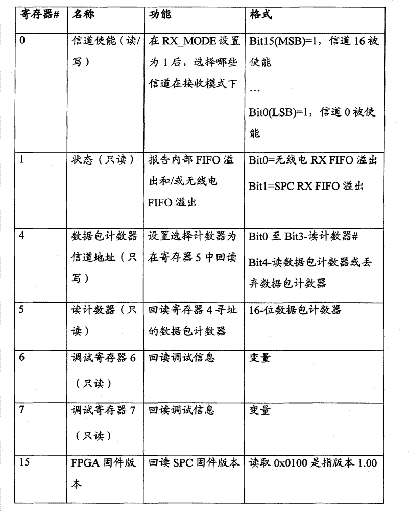
除了经ADDR[3:0]引脚选择无线电收发机38中的一个和向所选的收发机38发送控制或配置数据之外,CPU42还可以,例如,通过将ADDR4信号设置为高经/CS_SPC信号直接访问SPC40的内部寄存器。在这种方案下,ADDR[3:0]引脚可用来选择SPC40的16个内部寄存器中的一个。在一些实施例中,内部寄存器是16位宽。一个实施例中的SPC40的寄存器的确切功能在下表中定义。In addition to selecting one of the
在实施例中,当/CS_SPC变高时,在SCLK信号的上升沿时钟输入寄存器数据并将其保存在适当的寄存器中。In an embodiment, register data is clocked in on the rising edge of the SCLK signal and saved in the appropriate register when /CS_SPC goes high.
在接收模式下,SPC40中的独立的状态机处理来自相应的收发机38的数据包并为每个接收的数据包产生时间戳。收发机38可将所有层采集的数据包转发到SPC40,采集的数据包括PHY报头和可能的前导码。当RX_MODE引脚设置为1时,SPC40自动发送命令(SRX-ON)至每个使能的无线电收发机38(使用如上表中所描述的信道使能寄存器0是可识别的)来开始接收。接下来结合图6A和6B并继续参照图5的信号图来讨论在接收模式下的SPC40的运行,以及在接收模式下所使用的组件。In receive mode, a separate state machine in the
通常,每个无线电收发机38设置到一组通信信道中的一个不同的信道上,该通信信道用于在网络1中发送数据包。如上所述,网络分析仪2因此可以采集在网络1的所有通信信道上发生的通信。然而,网络分析仪2优选地允许用户通过用户界面20编程无线电收发机38中的任何一个以在任何802.15.4标准信道上运行。举例来说,用户可配置RF接口14的所有无线电收发机38以接收相同信道上的通信,以便确定通信信道之间的RSSI信号强度变化。这种运行模式以下称为校准模式。Typically, each
如上所述,CPU42和SPC40使用信号RXDATA[7:0]、READ_DATA和/RX-INT来将数据包传送至CPU42以及,特别是使用RXDATA引脚来从相应的FIFO缓冲器读取字节。当从接收模式转换回设置模式(即RX-MODE引脚变低),SPC40可自动清除与接收模式相关的内部状态,并刷新所有FIFO缓冲器。As mentioned above,
图6A示意地示出了与在SPC40的接收模式下执行的独立的状态机70相关的信令。每个状态机70连接到并服务相应的无线电收发机38。参照前面的图4,独立的状态机70可以是相应独立的无线电控制模块54的组件。特别是,每个独立的状态机70可负责响应于检测到数据包开始传送生成时间戳、负责响应于检测到数据包传送结束启动从相应的无线电收发机38的数据包的传送、以及负责响应于检测到整个数据包已经从无线电收发机38传送到SPC40的信道专用的内部缓冲器而停止数据传送。根据一个实施例的状态机70的状态跃迁图示出,并结合图6B并进行更详细的讨论。FIG. 6A schematically shows the signaling associated with a
继续参照图6A,时钟源72为计数器74提供周期时钟信号,所述计数器例如可以是40位整数计数器。时钟源72可以是精确的低漂移晶体时钟,在整个超过12.7天的时间间隔内具有1微秒的分辨率和精度。如果需要,例如,时钟源72可单独通过SPC40来提供,以通过专用的引脚向SPC40提供时钟信号。每个状态机70都通信连接到计数器74,以便在相应的收发机38上检测到数据包开始传送时,就立即为从收发机38中的任一个接收的数据包生成时间戳,而不用考虑在其它通信信道上检测到的数据包的个数。每个状态机70可执行相应的分组格式化器76(这可以是图4中所示的无线控制模块54的另一个组件)。在将数据包添加到相应的FIFO队列或缓冲器上之前,分组格式化器76可将计数器74(定义时间戳)的当前值附加、预置或以其它方式附加到数据包上。作为另外一种选择,SPC40可仅包括一个分组格式化器,状态机70可使计数器74的当前值存储在寄存器或缓冲器中,以备分组格式化器随后使用。应当注意,一般来说,只有一些数据包的处理需要在所有的通信信道上进行并行处理。作为另外一种选择,SPC40可包括多个由共同时钟信号驱动的计数器74。Continuing to refer to FIG. 6A , the clock source 72 provides a periodic clock signal for a
每个状态机70可根据图6B所示的状态跃迁图90来执行。在这个实施例中,状态跃迁图90包括闲置状态,在此期间,SPC40既不从相应的收发机38传送数据包,也不在收发机38上寄存新数据包的接收。状态机70可跃迁到状态94,其中当对应的SFD_n信号从0变为1时,在收发机38上开始接收新的数据包。例如,调谐到和通信信道3相连的频率F3(见图1)的收发机38可检测802.15.4协议栈的物理层上的数据包的前导码,并随后检测指示数据包开始发送的帧起始定界符(SFD)字段。当检测帧定界符时,收发机38可立即在收发机38的输出SFD引脚上输出1。由于此例中的收发机38与通信信道3相连,所以SPC40在连接到服务通信信道3的状态机70上的SFD_3上接收1。Each
在图6B中使用的符号中,触发箭头所示事务的事件列在正斜杠的左边,响应于进入新状态之前的事件而采取的行动列在了正斜杠的右边。因此,如图6B所示,状态机70可响应于检测到相应的SFD_n信号现在是1而生成时间戳。从某种意义上来说,SFD_n信号用于为相应的通信信道“冻结”数据包时间戳。一旦接收到了数据包的最后的字节,收发机38会将FIFOP_n信号变为高。此信号使状态机70生成数据包报头、启动SPI传送以便从无线电FIFO缓冲器中读取数据包字节并跃迁到状态96。在实施例中,每个信道专用的FIFO缓冲器可达2Kb深。In the notation used in Figure 6B, the events that trigger the transactions indicated by the arrows are listed to the left of the forward slash, and the actions taken in response to events prior to entering the new state are listed to the right of the forward slash. Thus, as shown in FIG. 6B ,
在状态96下检索数据包之前,SPC40可生成识别接收数据包的信道上的报头和5字节长的时间戳。在状态96下在从接收机38检索数据包之前,SPC40可将生成的报头插入相应的FIFO缓冲器中。在一些实施例中,数据包报头数据格式可定义如下:Before retrieving the data packet in

根据该实例格式,信道字节的低四位在0到15的范围内,用来表示数据包的物理信道。网络分析仪2的软件可在设置模式下将此物理信道映射到802.15.4标准信道。信道字节的高四位具有来自以上定义的SPC寄存器#1的状态位的副本。时间戳优选为40位值,其分辨率为每位1微秒。这样的分辨率可使得数据包采集期超过12.7天而无意外。当SPC40在上电时重置时,时间戳计数器设置为0。According to the example format, the lower four bits of the channel byte range from 0 to 15, and are used to indicate the physical channel of the data packet. The
在状态96下,状态机70可检索收发机38上的数据包。在其它实施例中,状态机70可以读取状态96下的多个数据包,在每次接收后不会跃迁回状态92。然而,时间戳生成和插入可以需要做相应的调整。一般来说,在状态96下的传送可以通过相应的SPI接口(即,MISO_n、MOSI_n和SCLK_n引脚)进行。In
在执行WirelessHART的实例网络1中,数据包的长度达128个字节。第一个字节表示其余的数据包的字节长度。SPC状态机首先读取长度字节并用其来读取数据包的剩余字节。作为另外一种选择,SPC40可以只读取来自无线电收发机38的字节,直到FIFO_n引脚变低表明不再有字节可读取。In
根据需要,SPC40还可以在存储在相应FIFO中的数据包的末端附加长度校验字节。这个附加的字节用于同步之目的以及数据包边界的确认。任何长度字节大于127的数据包都可视为无效并可丢弃。当丢弃发生时,可增加数据包丢弃计数器。还可以采集具有有效长度但具有循环冗余校验(CRC)错误的数据包。数据包最后的字节可以包括表明数据包是否有CRC错误的位。According to needs, SPC40 can also add a length check byte at the end of the data packet stored in the corresponding FIFO. This additional byte is used for synchronization purposes and confirmation of packet boundaries. Any packet with length bytes greater than 127 is considered invalid and may be discarded. When a drop occurs, the packet drop counter may be incremented. Packets with a valid length but with cyclic redundancy check (CRC) errors can also be captured. The last byte of the data packet may include bits indicating whether the data packet has CRC errors.
一旦已接收到数据包、时间戳记并存储在适当的信道专用的FIFO存储器中,则SPC40可以进行通知CPU42可对新数据进行检索以及通过分组服务器16、并最终通过分组客户端24(见图1)中的一个来进行后续处理。为此,SPC40可通过断言/RX-INT引脚生成中断。CUP42可通过以下方式作出响应:通过RXDATA[7:0]引脚读取数据包的字节、切换READ_DATA引脚以促使FIFO读出下一个字节、检查以查看是否/RX_INT引脚仍然被断言(即,检查整个数据包是否已经被传送)和继续检索数据包的单个字节直到/RX_INT引脚被取消断言。Once a data packet has been received, time stamped, and stored in the appropriate channel-specific FIFO memory, the
在一些实施例中,为了确保CPU42能在下一个中断到来之前检测出被取消断言的/RX-INT引脚,SPC40等待发出任何未决中断,直到READ_DATA信号由CPU42切换一个附加时间之后。In some embodiments, to ensure that the
此外,SPC40可适于高效和安全的处理溢出。虽然SPC40优选地足够快以避免在正常情况下的溢出,但是,溢出仍然可能发生,如果例如收发机38中的一个接收的数据包的长度大于最大长度128个字节。在这种情况下,在FIFOP_n在数据包末端变高之后,溢出可通过变低的FIFO_n信号来指示。在实施例中,SPC40检测到这种情况并向相应的收发机38发出命令来刷新相连的FIFO存储器并恢复运行。在这种情况下,FIFO缓冲器中的一些数据会丢失,相应的时间戳不再使用。如果需要的话,可以使用例如来自SPC40的引脚上的LED48中的一个来报告这种情况。Additionally, the SPC40 can be adapted for efficient and safe handling of spills. Although
进一步关于用于驱动状态机70的时钟信号,时钟源72(见图6A0)可以是CLK-16MHz输入引脚。这个信号可以是高度精确的时钟(+-1.5ppm),也可用于驱动时间戳计数器74和XCVR_CLK[16:0]信号。在这种情况下,SPC40可以简单地用作XCVR_CLK_n输出的分配缓冲器。如果需要的话,附加的XCVR_CLK_16信号可进入无线电收发机50。Further regarding the clock signal used to drive the
此外,SPC_CLK输出引脚可以是状态机70所用的内部时钟。这个信号优选地是由SPC40的内部锁相环(PLL)生成的40MHz时钟,并且这个时钟信号可在引脚上输出以用于SPC_CLK测试之目的。Additionally, the SPC_CLK output pin may be an internal clock used by
如上所述,CPU42还可以通过在/RESET_SPC输入上发出低脉冲来完全重置SCP40。在这种情况下,SPC40可以将一个或多个计数器70、内部寄存器和所有内部FIFO缓冲器设置为0。SPC40还可以将所有状态机重置为闲置状态。SPC40还可以将单个/NRESET信号发送到所有收发机38上。优选地,当SPC40通过/RESET_SPC信号重置时,这个信号的脉冲调为低。
当在校准模式下工作时,网络分析仪2可将所有收发机38调谐到相同的载频。然后RF接口14可在每个通信信道上接收相同的控制信号、测量每个通信信道上的RSL并使用获得的RSL测量值来补偿在后续处理中信道专用的信号衰减的变化。换句话说,网络分析仪2可在同一频率上运行收发机38,以便减少或完全消除在接收机灵敏度上信道至信道间的变化,从而有效并精确地校准RF接口14。控制信号可包括由网络1中的设备D1至D7发送的实际的数据包或来自控制发射机的信号。在一个实施例中,网络分析仪2可使用收发机50来生成具有控制的强度和/或其它参数的控制信号。应当理解,跨多个通信信道的RF接口14的精确校准使得网络分析仪2可估计被测设备(即,图1中所示的设备D1至D7中的一个)发出的信号强度。When operating in calibration mode,
接下来,图7从串行接口信令的角度示出了CPU42、SPC40和收发机38和50之间的交互。特别地,图7仅示出了与串行接口信令相关的那些引脚或信号,并且为了说明清晰之目的而省略了其它引脚或信号。应当理解图7中的CPU42相对于SPC40作为主设备而运行,其继而,相对于收发机38和50作为主设备而运行。虽然CPU42和单一从设备(SPC40)一起运行,但是SPC40的CPU接口包括作为从选择信号而运行的ADDR引脚(见图5)。如上所讨论,图7中所示的配置有利地允许SPC40为个体信道专用的FIFO队列提供缓冲、并行处理、时间戳记、独立管理等等。Next, Figure 7 shows the interaction between
如上所述,应当理解通常无线电接口14,尤其是SPC40允许客户端应用程序24(见图1)接收有关在网络1中发送的数据包的时序的准确信息。而传统的处理器只能以伪并行的方式(即,通过分割CPU时间)来服务多个数据流,SPC40将诸如时间戳的重要信息以真正并行的方式寄存在多个通信信道上。众所周知,传统处理器上的并行处理一般涉及将可用的CPU时间分割成多个周期以供并行任务使用,并按照某种算法或选择原则在任务之间转换(即,“上下文转换”)。从这个意义上讲,上述并行处理仅仅是准并行,其中在给定点上CPU仅执行一个任务。As mentioned above, it should be understood that the
为了更好地说明与这种方法相关的一些优点,图8示出了时序图,其中数据包在时间T1在通信信道0上接收,如由在时间T1上变高的SFD_0信号所示,并且另外两个数据包在时间T2分别在通信信道1和2上同时接收。如果使用诸如SPC40的数据包处理器,则如果在时钟信号的下降沿上发生跃迁,则数据包在通信信道0、1和2上的到达可以在时间T3检测到。因此即使这三个数据包在CLK信号的一个周期内到达,所有这三个数据包也可获得相同的时间戳。To better illustrate some of the advantages associated with this approach, Figure 8 shows a timing diagram where a packet is received on
一般来说,时间戳精度可受限于CLK信号的分辨率。在时间T4在通信信道N上检测的数据包可相应地获得与不同于时间T3的时间T5相关的时间戳,而尽管时间T1和T2之间有差异,但是通信信道1和2上检测的数据包在时间T3上仍然获得相同的时间戳。In general, time stamp accuracy may be limited by the resolution of the CLK signal. A data packet detected on communication channel N at time T4 may correspondingly obtain a time stamp associated with time T5 different from time T3, while a data packet detected on
此外,应当注意SPC40不需要在定界符字段开始的时候触发时间戳。如果,例如,已知所有数据包都使用相同的PHY前导码和/或报头的格式,SPC40可使用从收发机38中接收的其它信号或相同信号的不同跃迁来触发。例如,如果SPC40在SFD_n在时间T6、T7或T9从高跃迁为低的时候触发,则时间戳的相对精度可能是相同的。Also, it should be noted that the
接下来,图9示出了可在网络分析仪2中使用的RF信令路径的另一个实施例。虽然与图3中的实施例不同,但是图9中所示的配置还允许网络分析仪2使用单天线。而图3示出了使用单带通滤波器和高增益放大器32来处理整个802.15.4标准频谱上接收的RF信号的配置,图9示出了替代形式的RF信号路径98,其中单带通滤波器100设置在RF输入和驱动第一四路分配器34的一级放大器102之间。随后二级放大器104提供在分配器34和四路分配器36a-36d之间。然而,看起来利用USB电源比用图9中所示的五个单独的放大器更容易驱动图3中的单级放大器32。此外,希望使用平衡-不平衡转换器将无线电38连接到本身带有低段计数的天线连接器。一种可能的平衡-不平衡转换器仅需要两个组件而不是七个。Next, FIG. 9 shows another embodiment of an RF signaling path usable in the
在实施例中,SPC40可包括执行串行从模式配置的XilinxXC3S1000-FT256 FPGA。在这种模式下,CPU42通过FPGA上的CCLK、DIN、DONE、INIT_B & PROG_B引脚来控制加载FPGA代码。所述代码本身保存在与CPU42连接的串行闪存44中。CPU42需要在上电时间下载FPCA代码。更多详情可在有关使用微处理器来配置Xilinx FPGA的Xilinx使用手册(XAPP502)中找到。此外,无线电收发机38可以是TI/Chipcon CC2420芯片,可以通过定制FPCA来使用此收发机的单接口。图10-13示出了RF接口14的各种组件的电路图,至少其中一些所述组件包括CC2420芯片。In an embodiment,
综上所述,应当理解结合图3至图9所讨论的无线电接口14提供了许多重要的优点,其包括,例如,在多个通信信道上同时采集通信、并行处理采集的数据流(并且特别是精确的时间戳记)、采集包括物理层的所有层的数据包的能力等。由于使用了相同的时钟信号来处理多个数据流,所以确保了跨所有16个信道的时间同步性,并且在PHY定界符接收时生成精确的时间戳。此外,可根据需要,RF接口14可使用单天线运行以在16个或更多的通信信道上采集数据包。一般来说,至少在理论上还可能使用多个天线,可为每个通信信道提供诸如芯片天线的单独天线。然而,测试已经证明将相当多的天线彼此靠近放置就会产生明显的干扰,有时足以导致网络分析仪2偶尔丢包。In summary, it should be appreciated that the
重新参照图2,网络分析仪2的架构有效地将任务分为那些由硬件或固件最优执行的任务和那些由软件最佳执行的任务。因此,数据包分析仪或类似的分组客户端24执行解码数据包、处理用户命令、以文本和/或图解方式显示数据包的“繁重的工作”等。此外,设计图1中的分组服务器16,以便将数据包从RF接口14传送到用户界面应用程序20并相应地格式化数据包。分组服务器16的命令行参数可以如下:Referring back to Figure 2, the architecture of the
-p 端口-p port
用于建立双向配置和控制至分组客户端24和/或用户界面20的连接的服务器端口(缺省:1024)Server port used to establish bi-directional configuration and control connections to
-1 描述符-1 descriptor
ISO 639指定的语言描述字符串(缺省:“en”)Language description string as specified by ISO 639 (default: "en")
-d-d
在调试模式下运行,自stdin获得输入并将采集数据包发送到stdout。通过经stdin发送^C来停止采集。如果该选项没有指定,则消息服务器在启动采集之前将等待控制端口上的控制命令Runs in debug mode, takes input from stdin and sends capture packets to stdout. Stop acquisition by sending ^C via stdin. If this option is not specified, the message server will wait for a control command on the control port before starting the collection
-O stdout-O stdout
带有可选路径的文件名称(缺省:″analysaeout.txt″)filename with optional path (default: "analysaeout.txt")
-G stdlog-G stdlog
带有可选路径的文件名称(缺省:″analysaelog.txt″)filename with optional path (default: "analysaelog.txt")
-E stderr-E stderr
带有可选路径的文件名称(缺省:″analysaeerr.txt″)filename with optional path (default: "analysaeerr.txt")
用户界面20和分组服务器16可使用TCP数据端口和TCP控制端口来相互通信。在操作中,用户界面20可首先评估用于应用程序的配置和控制的连接端口。在一个实施例中,“本地主机”上的控制端口是TCP端口“ANALYS_WH_UI_CONNECT”(本地主机指采集引擎10所运行的主机12,而ANALYS_WH_UI_CONNECT是用于默认端口号的编译时常量)。
在经ANALYS_WH_UI_CONNECT端口将用户界面20连接到采集引擎10的分组服务器16之后,可以ASCII文本格式的十进制数来提供其它单向数据端口号。负数可表明数据流分配错误或其它错误情况。用户界面20还可显示附接到分组服务器16上的USB设备清单。After connecting the
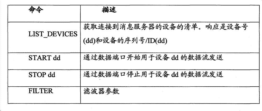
用户界面20可以利用配置和控制端口来将配置和控制命令发送至分组服务器16。如果消息服务器16接受所述命令,其则优选通过应答来响应。如果所述命令中包含错误或者如果分组服务器16由于某种原因无法完成命令,则分组服务器16会和说明原因的文本字符串一起来优选地通过否定应答来响应。下表提供了分组服务器16可识别的控制端口命令的例子:
在网络分析仪2工作期间,采集引擎10可将数据流提供给用户界面20和/或分组客户端24,所述分组客户端24包括在几个无线信道上采集的数据包以及在其它设备和网络诊断中有用的信息。例如,数据流可包括一些或所有的字段描述(如,“802.15.4-DATA”)、数据包号(如,持续增加的32位数以记录每个采集的数据包)、日期和时间、时间戳、RSL、数据包状态、信道、字节流、USB设备号。此外,数据流可以包括用于指定数据包在其上采集的USB设备的字段USB设备号。During operation of
在一些实施例中,日期和时间字段包括ISO 8601日期字符串、空格字符以及ISO 8601时间字符串。第二个字段后紧随小数点和毫秒数。这种配置类似于随着毫秒数的增加而调用“%Y-%m-%d%H:%M:%S”的格式化字符串的标准ANSI C库函数strftime的输出。同时,字段实耗时间可以包含自采集系统上次重置以来的毫秒数。实耗时间每隔8μS就报告一次,并可具有至少8μS的精度。时间优选地表示为精确到小数点右边三位数的浮点数。所述值在至少48小时内不应溢出。In some embodiments, the date and time fields include ISO 8601 date strings, space characters, and ISO 8601 time strings. The second field is followed by a decimal point and milliseconds. This configuration is similar to the output of the standard ANSI C library function strftime calling the format string of "%Y-%m-%d%H:%M:%S" with increasing number of milliseconds. Also, the field elapsed time can contain the number of milliseconds since the acquisition system was last reset. The elapsed time is reported every 8 μS and may have an accuracy of at least 8 μS. Times are preferably represented as floating point numbers accurate to three digits to the right of the decimal point. The value should not overflow for at least 48 hours.
RSL字段可以表明每个数据包的接收信号的水平,包括为接收的数据包提供信号的功率级(以dB为单位)的估计。这个值可表示并存储为-128和+127之间的带符号的整数。The RSL field may indicate the received signal level for each packet, including providing an estimate of the power level (in dB) of the signal for the received packet. This value can be represented and stored as a signed integer between -128 and +127.
此外,数据包状态可以是数据包的无符号的16位列举状态。该状态可以显示以下值:例如:Bit 0-数据包FCS错误;Bit 1-错误接收字节计数;Bit2-接收机溢出。Bit 3至Bit 15被保留。Additionally, the packet status may be an unsigned 16-bit enumerated status of the packet. The status can display the following values: For example: Bit 0-packet FCS error; Bit 1-error received byte count; Bit2-receiver overflow.
更进一步,字段信道包含按IEEE 802.15.4-2006规范规定的十进制信道号。字段字节流优选地包含所有数据包中接收的字节。每个字节可由空格字符隔开并包括2个十六进制字符。Furthermore, the field channel contains the channel number in decimal as specified in the IEEE 802.15.4-2006 specification. The field byte stream preferably contains all bytes received in the packet. Each byte can be separated by a space character and consists of 2 hexadecimal characters.
一般情况下,所有字段可以是由逗号隔开的ASCII文本,并且数据包优选地由换行来终止。所得的数据流的例子如下:In general, all fields may be ASCII text separated by commas, and packets are preferably terminated by newlines. An example of the resulting data flow is as follows:
1,802.15.4-DATA,10523,2007-07-16 14:04:31.261,6581973.929,-14,0x0000,23,5B 41 88 2C 1100...1, 802.15.4-DATA, 10523, 2007-07-16 14:04:31.261, 6581973.929, -14, 0x0000, 23, 5B 41 88 2C 1100...
重复)。repeat).
图14提供了网络分析仪2的组件的有利配置的另一个实例。在此实施例中,分组客户端24连接到多种情况下的分组服务器16上。每个分组服务器16将数据包流发送至分组客户端24,以便分组客户端24可以方便地显示来自多个物理位置的信息。此外,一些分组服务器16可连接到多个RF接口,也如图14中所示。因此,单个分组客户端24可以收集与多个通信信道和物理位置相关的相对大量的信息。FIG. 14 provides another example of an advantageous arrangement of components of the
因为图14中所示的分组客户端24可以收集相对大量的数据,所以可以进一步提供滤波功能,以基于各种标准来选择诸如自特定设备发送或从其上接收的数据包。重新参照图1,例如,操作人员可能希望看到所有经过设备D2的数据包。他或她可因此选择合适的滤波器并用所选的滤波器来阻止所有与D2无关的数据包。人们可预期此功能在检验某设备遵守网络1的协议(如WirelessHART)时可以是特别有用的。Because the
人们还可预期网络分析仪2可以用于自动测试的执行以及测试说明。特别地,响应于来自分组客户端24的相应的命令,可以提供分组服务器16以执行预定的测试方案。换句话说,网络分析仪2可以处理寻址至网络分析仪2本身的数据包。例如,数据包可以用于指导网络分析仪2启动和停止记录数据、指定记录数据的文件名、提供在测试过程中可以使用的应用中的密钥等。网络分析仪2可创建特定的目录(如,在主机12的内存磁盘上),其中分组服务器16可将在执行特定测试方案过程中收集的数据包引入所述目录中。通过这种方式,可大大减少必须通过操作人员人工分析的信息量。It is also contemplated that the
虽然以上内容陈述了许多不同实施例的具体实施方式,但是应当理解本专利的范围是由在本专利末尾所给出的权利要求书的文字来限定。这些具体实施方式被认为仅是示例性的并且没有描述每个可能的实施例,原因是描述每个可能的实施例是不切实际的,如果不是不可能。使用现有的技术或本专利提交日期之后研发的技术,许多可供选择的实施例可以实施,但其将仍在本权利要求书的范围之内。While the above has set forth a detailed description of many different embodiments, it should be understood that the scope of this patent is defined by the words of the claims presented at the end of this patent. The detailed description is considered to be exemplary only and does not describe every possible embodiment, since describing every possible embodiment would be impractical, if not impossible. Many alternative embodiments could be implemented, using either current technology or technology developed after the filing date of this patent, which would still fall within the scope of the claims.
Claims (39)
Applications Claiming Priority (3)
| Application Number | Priority Date | Filing Date | Title |
|---|---|---|---|
| US7495408P | 2008-06-23 | 2008-06-23 | |
| US61/074,954 | 2008-06-23 | ||
| PCT/US2009/048342 WO2010008867A2 (en) | 2008-06-23 | 2009-06-23 | Wireless communication network analyzer |
Publications (2)
| Publication Number | Publication Date |
|---|---|
| CN102113367A CN102113367A (en) | 2011-06-29 |
| CN102113367B true CN102113367B (en) | 2013-11-20 |
Family
ID=41550959
Family Applications (1)
| Application Number | Title | Priority Date | Filing Date |
|---|---|---|---|
| CN2009801307989A Expired - Fee Related CN102113367B (en) | 2008-06-23 | 2009-06-23 | Wireless communication network analyzer |
Country Status (5)
| Country | Link |
|---|---|
| US (2) | US8441947B2 (en) |
| EP (1) | EP2294858A4 (en) |
| JP (1) | JP2011527146A (en) |
| CN (1) | CN102113367B (en) |
| WO (1) | WO2010008867A2 (en) |
Families Citing this family (25)
| Publication number | Priority date | Publication date | Assignee | Title |
|---|---|---|---|---|
| US9730078B2 (en) * | 2007-08-31 | 2017-08-08 | Fisher-Rosemount Systems, Inc. | Configuring and optimizing a wireless mesh network |
| US8121826B1 (en) * | 2009-07-17 | 2012-02-21 | Xilinx, Inc. | Graphical user interface for system design |
| JP5573053B2 (en) * | 2009-09-04 | 2014-08-20 | ソニー株式会社 | Wireless communication apparatus and wireless communication method |
| US8351404B2 (en) * | 2009-09-25 | 2013-01-08 | Nigel Iain Stuart Macrae | Method and apparatus for multiple accesses to a communications channel |
| US8363693B2 (en) * | 2010-04-16 | 2013-01-29 | Hitachi, Ltd. | Adaptive frequency hopping in time-slotted based wireless network |
| US10504360B2 (en) * | 2011-04-08 | 2019-12-10 | Ross Gilson | Remote control interference avoidance |
| US8914053B2 (en) * | 2011-11-11 | 2014-12-16 | Fujitsu Limited | System and method for selecting transceivers to provide wireless communication service for a wireless user endpoint |
| US9176919B2 (en) * | 2012-06-06 | 2015-11-03 | Honeywell International Inc. | Process controller having multi-channel serial communications link |
| US9418037B2 (en) * | 2012-07-11 | 2016-08-16 | Infineon Technologies Ag | SPI interface and method for serial communication via an SPI interface having an SPI protocol handler for evaluating signal transitions of SPI signals |
| EP2915287B1 (en) | 2012-10-30 | 2018-12-05 | Viavi Solutions Inc. | Method and system for identifying matching packets |
| JP6094562B2 (en) * | 2014-11-06 | 2017-03-15 | 横河電機株式会社 | Recorder |
| US9842071B2 (en) * | 2014-11-11 | 2017-12-12 | Microchip Technology Incorporated | Multi-channel I2S transmit control system and method |
| WO2017026248A1 (en) * | 2015-08-07 | 2017-02-16 | ソニー株式会社 | Receiving device and data processing method |
| MX377715B (en) * | 2015-08-07 | 2025-03-11 | Sony Corp | Reception device and data processing method |
| WO2017138620A1 (en) * | 2016-02-09 | 2017-08-17 | 株式会社 東芝 | Memory device, edge device handling accumulable data, and data management method |
| US10277384B2 (en) * | 2017-04-04 | 2019-04-30 | Cisco Technology, Inc. | Intermediate distribution frame for distributed radio heads |
| US9734099B1 (en) * | 2017-04-27 | 2017-08-15 | Micro Lambda Wireless, Inc. | QSPI based methods of simultaneously controlling multiple SPI peripherals |
| CN107144751B (en) * | 2017-06-09 | 2020-06-09 | 中国电子科技集团公司第四十一研究所 | A multi-channel vector network parameter analysis system and method |
| FR3068797B1 (en) | 2017-07-04 | 2019-07-19 | STMicroelectronics (Grand Ouest) SAS | METHOD OF COMMUNICATION BETWEEN A MASTER DEVICE AND N SLAVES CONNECTED ON A SYNCHRONOUS DATA BUS OF THE SPI TYPE AND CORRESPONDING DEVICE |
| US10484109B2 (en) * | 2018-02-22 | 2019-11-19 | Rohde & Schwarz Gmbh & Co. Kg | Test arrangement and test method |
| KR102772057B1 (en) * | 2018-12-19 | 2025-02-25 | 마이크론 테크놀로지, 인크 | Memory devices, modules and systems having memory devices with varying physical dimensions, memory formats, and operational capabilities |
| EP3709177B1 (en) * | 2019-03-13 | 2021-03-03 | Axis AB | Serial peripheral interface master |
| JP7242389B2 (en) * | 2019-04-11 | 2023-03-20 | 株式会社東芝 | Packet generator and method |
| RU2762040C1 (en) * | 2020-11-06 | 2021-12-15 | СВИ Коммуникатионс-унд Компутер ГмбХ | System for combining digital streams and method for combining digital streams (variants) |
| US11418969B2 (en) | 2021-01-15 | 2022-08-16 | Fisher-Rosemount Systems, Inc. | Suggestive device connectivity planning |
Citations (2)
| Publication number | Priority date | Publication date | Assignee | Title |
|---|---|---|---|---|
| US20040095951A1 (en) * | 2002-10-30 | 2004-05-20 | Lg Electronics Inc. | Digital filter of a mobile communication system and operating method thereof |
| US20080120676A1 (en) * | 2006-11-22 | 2008-05-22 | Horizon Semiconductors Ltd. | Integrated circuit, an encoder/decoder architecture, and a method for processing a media stream |
Family Cites Families (153)
| Publication number | Priority date | Publication date | Assignee | Title |
|---|---|---|---|---|
| JPH0771097B2 (en) | 1985-12-20 | 1995-07-31 | 株式会社日立製作所 | Time division multiplex communication system |
| US5159592A (en) | 1990-10-29 | 1992-10-27 | International Business Machines Corporation | Network address management for a wired network supporting wireless communication to a plurality of mobile users |
| US5459855A (en) * | 1992-08-10 | 1995-10-17 | Hewlett-Packard Company | Frequency ratio detector for determining fixed frequency ratios in a computer system |
| ATE187824T1 (en) * | 1994-10-24 | 2000-01-15 | Fisher Rosemount Systems Inc | DEVICE THAT ALLOWS ACCESS TO FIELD DEVICES IN A DISTRIBUTED CONTROL SYSTEM |
| US5535193A (en) * | 1995-02-09 | 1996-07-09 | Wandel & Goltermann Technologies, Inc. | Multiport analyzing with time stamp synchronizing |
| US5719859A (en) * | 1995-09-19 | 1998-02-17 | Matsushita Electric Industrial Co., Ltd. | Time division multiple access radio communication system |
| US5781549A (en) * | 1996-02-23 | 1998-07-14 | Allied Telesyn International Corp. | Method and apparatus for switching data packets in a data network |
| US6901299B1 (en) * | 1996-04-03 | 2005-05-31 | Don Whitehead | Man machine interface for power management control systems |
| US6701361B1 (en) * | 1996-08-22 | 2004-03-02 | Intermec Ip Corp. | Enhanced mobility and address resolution in a wireless premises based network |
| US6424872B1 (en) * | 1996-08-23 | 2002-07-23 | Fieldbus Foundation | Block oriented control system |
| US6430268B1 (en) * | 1997-09-20 | 2002-08-06 | Statsignal Systems, Inc. | Systems for requesting service of a vending machine |
| US6233327B1 (en) * | 1997-02-14 | 2001-05-15 | Statsignal Systems, Inc. | Multi-function general purpose transceiver |
| US7137550B1 (en) | 1997-02-14 | 2006-11-21 | Statsignal Ipc, Llc | Transmitter for accessing automated financial transaction machines |
| US7079810B2 (en) * | 1997-02-14 | 2006-07-18 | Statsignal Ipc, Llc | System and method for communicating with a remote communication unit via the public switched telephone network (PSTN) |
| US5926531A (en) * | 1997-02-14 | 1999-07-20 | Statsignal Systems, Inc. | Transmitter for accessing pay-type telephones |
| US6618578B1 (en) | 1997-02-14 | 2003-09-09 | Statsignal Systems, Inc | System and method for communicating with a remote communication unit via the public switched telephone network (PSTN) |
| US6628764B1 (en) | 1997-02-14 | 2003-09-30 | Statsignal Systems, Inc. | System for requesting service of a vending machine |
| US6198751B1 (en) * | 1997-11-19 | 2001-03-06 | Cabletron Systems, Inc. | Multi-protocol packet translator |
| US6457038B1 (en) | 1998-03-19 | 2002-09-24 | Isochron Data Corporation | Wide area network operation's center that sends and receives data from vending machines |
| FI114745B (en) | 1998-06-01 | 2004-12-15 | Metso Automation Oy | Control systems for field devices |
| US6914533B2 (en) * | 1998-06-22 | 2005-07-05 | Statsignal Ipc Llc | System and method for accessing residential monitoring devices |
| US6522974B2 (en) * | 2000-03-01 | 2003-02-18 | Westerngeco, L.L.C. | Method for vibrator sweep analysis and synthesis |
| US6891838B1 (en) | 1998-06-22 | 2005-05-10 | Statsignal Ipc, Llc | System and method for monitoring and controlling residential devices |
| US6437692B1 (en) | 1998-06-22 | 2002-08-20 | Statsignal Systems, Inc. | System and method for monitoring and controlling remote devices |
| US6218953B1 (en) * | 1998-10-14 | 2001-04-17 | Statsignal Systems, Inc. | System and method for monitoring the light level around an ATM |
| US6028522A (en) * | 1998-10-14 | 2000-02-22 | Statsignal Systems, Inc. | System for monitoring the light level around an ATM |
| US6914893B2 (en) * | 1998-06-22 | 2005-07-05 | Statsignal Ipc, Llc | System and method for monitoring and controlling remote devices |
| US20060062192A1 (en) * | 1998-06-26 | 2006-03-23 | Payne William A Iii | Method for wireless access system supporting multiple frame types |
| US20020013679A1 (en) * | 1998-10-14 | 2002-01-31 | Petite Thomas D. | System and method for monitoring the light level in a lighted area |
| US7103511B2 (en) | 1998-10-14 | 2006-09-05 | Statsignal Ipc, Llc | Wireless communication networks for providing remote monitoring of devices |
| US7640007B2 (en) | 1999-02-12 | 2009-12-29 | Fisher-Rosemount Systems, Inc. | Wireless handheld communicator in a process control environment |
| US6747557B1 (en) * | 1999-03-18 | 2004-06-08 | Statsignal Systems, Inc. | System and method for signaling a weather alert condition to a residential environment |
| US7650425B2 (en) * | 1999-03-18 | 2010-01-19 | Sipco, Llc | System and method for controlling communication between a host computer and communication devices associated with remote devices in an automated monitoring system |
| US20040183687A1 (en) | 1999-03-18 | 2004-09-23 | Petite Thomas D. | System and method for signaling a weather alert condition to a residential environment |
| AU3592300A (en) | 1999-03-18 | 2000-10-04 | Statsignal Systems, Inc. | System for monitoring conditions in a residential living community |
| JP2000339345A (en) * | 1999-03-25 | 2000-12-08 | Sony Corp | Search system, search device and method, and input device and method |
| US6532507B1 (en) * | 1999-05-28 | 2003-03-11 | National Semiconductor Corporation | Digital signal processor and method for prioritized access by multiple core processors to shared device |
| US6487403B2 (en) | 1999-08-19 | 2002-11-26 | Verizon Laboratories Inc. | Wireless universal provisioning device |
| US7002958B1 (en) * | 1999-09-10 | 2006-02-21 | Pluris, Inc. | Method for load-balancing with FIFO guarantees in multipath networks |
| US6836477B1 (en) | 1999-12-23 | 2004-12-28 | Tekelec | Methods and systems for routing messages in a communications network |
| US6996100B1 (en) * | 2000-02-03 | 2006-02-07 | Telefonaktiebolaget Lm Ericsson (Publ) | Method and system for medium access on a radio channel |
| JP2001313672A (en) * | 2000-04-28 | 2001-11-09 | Toshiba Corp | Network system, packet relay device, wireless terminal, and packet processing method |
| US6996065B2 (en) * | 2000-07-06 | 2006-02-07 | Lucent Technologies Inc. | Dynamic backup routing of network tunnel paths for local restoration in a packet network |
| US6721779B1 (en) * | 2000-07-07 | 2004-04-13 | Softwired Ag | Messaging proxy system |
| FI114507B (en) | 2000-07-07 | 2004-10-29 | Metso Automation Oy | System for diagnostics of a device |
| US6643504B1 (en) * | 2000-07-10 | 2003-11-04 | At&T Corp. | Automatic wireless service activation in a private local wireless system |
| WO2002013412A1 (en) | 2000-08-09 | 2002-02-14 | Statsignal Systems, Inc. | Systems and methods for providing remote monitoring of electricity consumption for an electric meter |
| DE10042165C1 (en) * | 2000-08-17 | 2002-04-18 | Butzke Werke Aqua | System for controlling and monitoring sanitary fittings |
| GB0021440D0 (en) * | 2000-08-31 | 2000-11-01 | Cit Alcatel | An optical signal processor |
| US7519011B2 (en) | 2000-09-29 | 2009-04-14 | Intel Corporation | Frame structure for radio communications system |
| US20020031101A1 (en) * | 2000-11-01 | 2002-03-14 | Petite Thomas D. | System and methods for interconnecting remote devices in an automated monitoring system |
| US7870196B2 (en) * | 2000-11-08 | 2011-01-11 | Nokia Corporation | System and methods for using an application layer control protocol transporting spatial location information pertaining to devices connected to wired and wireless internet protocol networks |
| US20030026268A1 (en) * | 2000-11-28 | 2003-02-06 | Siemens Technology-To-Business Center, Llc | Characteristic routing |
| US6920171B2 (en) * | 2000-12-14 | 2005-07-19 | Motorola, Inc. | Multiple access frequency hopping network with interference anticipation |
| US7110380B2 (en) | 2001-02-07 | 2006-09-19 | Freescale Semiconductor, Inc. | System, method, and computer program product for sharing bandwidth in a wireless personal area network or a wireless local area network |
| US6937861B2 (en) * | 2001-02-13 | 2005-08-30 | Telefonaktiebolaget Lm Ericsson (Publ) | Connection management for dual mode access terminals in a radio network |
| DE10109196B4 (en) * | 2001-02-26 | 2005-04-28 | Viessmann Werke Kg | Apparatus and method for remote monitoring and parameterization of equipment, in particular of heating systems |
| US7075536B1 (en) | 2001-07-13 | 2006-07-11 | Cisco Technology, Inc. | Incremental plotting of network topologies and other graphs through use of markup language |
| US20030014535A1 (en) * | 2001-07-16 | 2003-01-16 | Oscar Mora | Collision avoidance method for home automation devices using an ethernet hub |
| US6959356B2 (en) | 2001-07-30 | 2005-10-25 | Fisher-Rosemount Systems, Inc. | Multi-protocol field device and communication method |
| US7346463B2 (en) * | 2001-08-09 | 2008-03-18 | Hunt Technologies, Llc | System for controlling electrically-powered devices in an electrical network |
| US7542867B2 (en) * | 2001-08-14 | 2009-06-02 | National Instruments Corporation | Measurement system with modular measurement modules that convey interface information |
| EP1293853A1 (en) | 2001-09-12 | 2003-03-19 | ENDRESS + HAUSER WETZER GmbH + Co. KG | Transceiver module for a field device |
| ATE372632T1 (en) * | 2001-09-27 | 2007-09-15 | Ericsson Telefon Ab L M | MULTI-JUNK ROUTING METHOD FOR DISTRIBUTED WLAN NETWORKS |
| US6970909B2 (en) | 2001-10-11 | 2005-11-29 | The Trustees Of Columbia University In The City Of New York | Multi-protocol data communication system supporting wireless telephony and content delivery |
| US6801777B2 (en) | 2001-11-27 | 2004-10-05 | Intel Corporation | Device and method for intelligent wireless communication selection |
| WO2003077328A2 (en) * | 2002-03-08 | 2003-09-18 | Epcos Ag | Method and device for filling housings of electric components with volatile liquids and for sealing said housings |
| US7920897B2 (en) * | 2002-03-14 | 2011-04-05 | Intel Corporation | Interference suppression in computer radio modems |
| US7079856B2 (en) | 2002-04-05 | 2006-07-18 | Lucent Technologies Inc. | Data flow control between a base station and a mobile station |
| US6765905B2 (en) | 2002-04-18 | 2004-07-20 | Motorola, Inc. | Method for reducing packet data delay variation in an internet protocol network |
| US20040028023A1 (en) * | 2002-04-18 | 2004-02-12 | Sarnoff Corporation | Method and apparatus for providing ad-hoc networked sensors and protocols |
| US7764617B2 (en) | 2002-04-29 | 2010-07-27 | Harris Corporation | Mobile ad-hoc network and methods for performing functions therein based upon weighted quality of service metrics |
| JP4133001B2 (en) * | 2002-06-12 | 2008-08-13 | シャープ株式会社 | Wireless communication system |
| DE50211013D1 (en) * | 2002-09-11 | 2007-11-15 | Tektronix Int Sales Gmbh | Method and device for monitoring a data transmission |
| KR100561393B1 (en) * | 2002-11-30 | 2006-03-16 | 삼성전자주식회사 | Method and system for controlling media access in wireless network |
| FR2850250B1 (en) | 2003-01-27 | 2005-03-25 | Lee Sara Corp | METHOD OF ASSEMBLING EDGE ON BOARD OF TWO TEXTILE PIECES |
| US6904327B2 (en) * | 2003-01-29 | 2005-06-07 | Honeywell International Inc. | Integrated control system to control addressable remote devices |
| EP1597840A2 (en) * | 2003-02-18 | 2005-11-23 | Extricom Ltd. | Multiplex communication between access points and hub |
| KR100948383B1 (en) | 2003-03-04 | 2010-03-22 | 삼성전자주식회사 | Efficient IP Address Allocation and Duplicate Detection in the ADHOC Network Environment |
| KR100887179B1 (en) * | 2003-05-27 | 2009-03-10 | 인터내셔널 비지네스 머신즈 코포레이션 | System for defining an alternate channel routing mechanism in a messaging middleware environment |
| US20040242249A1 (en) * | 2003-05-30 | 2004-12-02 | Neilson Paul Christian | Non-interfering multipath communications systems |
| US7460865B2 (en) | 2003-06-18 | 2008-12-02 | Fisher-Rosemount Systems, Inc. | Self-configuring communication networks for use with process control systems |
| US7436797B2 (en) | 2003-06-18 | 2008-10-14 | Fisher-Rosemount Systems, Inc. | Wireless architecture and support for process control systems |
| US7295519B2 (en) | 2003-06-20 | 2007-11-13 | Motorola, Inc. | Method of quality of service based flow control within a distributed switch fabric network |
| US7336642B2 (en) * | 2003-08-07 | 2008-02-26 | Skypilot Networks, Inc. | Communication protocol for a wireless mesh architecture |
| WO2005022280A1 (en) * | 2003-09-03 | 2005-03-10 | Unitronics (1989) (R'g) Ltd. | System and method for implementing logic control in programmable controllers in distributed control systems |
| US7436789B2 (en) * | 2003-10-09 | 2008-10-14 | Sarnoff Corporation | Ad Hoc wireless node and network |
| US7680033B1 (en) * | 2003-10-20 | 2010-03-16 | Ciena Corporation | Network manager circuit rediscovery and repair |
| JP4290529B2 (en) * | 2003-11-07 | 2009-07-08 | 株式会社バッファロー | Access point, terminal, encryption key setting system, encryption key setting method, and program |
| JP4193678B2 (en) | 2003-11-10 | 2008-12-10 | 沖電気工業株式会社 | Communication terminal and communication network |
| US7191021B2 (en) * | 2003-12-04 | 2007-03-13 | Honeywell International | Remote management of field devices in a manufacturing plant |
| US7818018B2 (en) * | 2004-01-29 | 2010-10-19 | Qualcomm Incorporated | Distributed hierarchical scheduling in an AD hoc network |
| JP2007527160A (en) | 2004-02-09 | 2007-09-20 | パケットホップ,インコーポレイテッド | Reliable message delivery method for ad hoc mesh networks using extended eMFC |
| KR101010774B1 (en) | 2004-02-11 | 2011-01-25 | 엘지전자 주식회사 | Point-to-Many Service Data Transmission / Reception in Mobile Communication System |
| US7216365B2 (en) * | 2004-02-11 | 2007-05-08 | Airtight Networks, Inc. | Automated sniffer apparatus and method for wireless local area network security |
| US7436790B2 (en) | 2004-03-25 | 2008-10-14 | Research In Motion Limited | Wireless access point methods and apparatus for reduced power consumption and cost |
| US7881239B2 (en) | 2004-03-27 | 2011-02-01 | Dust Networks, Inc. | Low-powered autonomous radio node with temperature sensor and crystal oscillator |
| US7420980B1 (en) | 2004-03-27 | 2008-09-02 | Dust Networks, Inc. | Digraph network superframes |
| US8194655B2 (en) * | 2004-08-05 | 2012-06-05 | Dust Networks, Inc. | Digraph based mesh communication network |
| US7529217B2 (en) * | 2004-03-27 | 2009-05-05 | Dust Networks, Inc. | Low-power autonomous node for mesh communication network |
| WO2005096722A2 (en) | 2004-03-27 | 2005-10-20 | Dust Networks | Digraph based mesh communication network |
| US20050228509A1 (en) | 2004-04-07 | 2005-10-13 | Robert James | System, device, and method for adaptively providing a fieldbus link |
| KR100595984B1 (en) * | 2004-04-12 | 2006-07-03 | 한국전력공사 | Control Network Transmission Frame Structure of Nuclear Distributed Control System |
| US7454173B2 (en) | 2004-04-23 | 2008-11-18 | Telefonaktiebolaget L M Ericsson (Publ) | Load control in shared medium many-to-one communication systems |
| US7697893B2 (en) | 2004-06-18 | 2010-04-13 | Nokia Corporation | Techniques for ad-hoc mesh networking |
| JP2006013612A (en) * | 2004-06-22 | 2006-01-12 | Traffic Shimu:Kk | Data monitoring system and program, recording medium, display operating method |
| US8441935B2 (en) * | 2004-08-09 | 2013-05-14 | Jds Uniphase Corporation | Method and apparatus to distribute signaling data for parallel analysis |
| US7606213B2 (en) * | 2004-08-12 | 2009-10-20 | Qualcomm Incorporated | Wireless MAC layer throughput improvements |
| US8098676B2 (en) * | 2004-08-12 | 2012-01-17 | Intel Corporation | Techniques to utilize queues for network interface devices |
| US20060045016A1 (en) * | 2004-08-31 | 2006-03-02 | Dawdy Jay J | Method and apparatus for managing packet data network loading |
| US20060067280A1 (en) * | 2004-09-29 | 2006-03-30 | Howard John S | Wireless medium access control protocol with micro-scheduling |
| US20060077917A1 (en) * | 2004-10-07 | 2006-04-13 | Honeywell International Inc. | Architecture and method for enabling use of wireless devices in industrial control |
| US7853221B2 (en) | 2004-11-12 | 2010-12-14 | Homerun Holdings Corp. | Network bridge device and methods for programming and using the same |
| US20060120384A1 (en) * | 2004-12-08 | 2006-06-08 | International Business Machines Corporation | Method and system for information gathering and aggregation in dynamic distributed environments |
| DE602005001315T2 (en) * | 2005-01-28 | 2008-02-14 | Research In Motion Ltd., Waterloo | Automatic integration of content from multiple data stores using a mobile communication device |
| US7586888B2 (en) * | 2005-02-17 | 2009-09-08 | Mobitrum Corporation | Method and system for mesh network embedded devices |
| DE102005008488B4 (en) * | 2005-02-24 | 2011-08-18 | VEGA Grieshaber KG, 77709 | Data transmission system for wireless communication |
| US7899027B2 (en) | 2005-03-23 | 2011-03-01 | Cisco Technology, Inc. | Automatic route configuration in hierarchical wireless mesh networks |
| US7975300B2 (en) * | 2005-04-15 | 2011-07-05 | Toshiba America Research, Inc. | Secure isolation and recovery in wireless networks |
| JP4763334B2 (en) | 2005-04-28 | 2011-08-31 | ルネサスエレクトロニクス株式会社 | Wireless ad hoc communication system and communication terminal synchronization method in wireless ad hoc communication system |
| US20060253584A1 (en) | 2005-05-03 | 2006-11-09 | Dixon Christopher J | Reputation of an entity associated with a content item |
| JP2006318148A (en) * | 2005-05-12 | 2006-11-24 | Yokogawa Electric Corp | Field equipment control system |
| US8473673B2 (en) * | 2005-06-24 | 2013-06-25 | Hewlett-Packard Development Company, L.P. | Memory controller based (DE)compression |
| US7375594B1 (en) * | 2005-07-12 | 2008-05-20 | Dust Networks, Inc. | Radio oscillator tuning |
| KR101199752B1 (en) * | 2005-09-08 | 2012-11-08 | 더 유니버시티 코트 오브 더 유니버시티 오브 에딘버그 | Hybrid wireless communication system and communicating method thereof |
| US7869378B2 (en) * | 2005-09-26 | 2011-01-11 | Interdigital Technology Corporation | Method and apparatus for sharing slot allocation schedule information amongst nodes of a wireless mesh network |
| US8014404B2 (en) * | 2005-09-30 | 2011-09-06 | Motorola Solutions, Inc. | Method and system for priority based routing |
| US8065680B2 (en) * | 2005-11-15 | 2011-11-22 | Yahoo! Inc. | Data gateway for jobs management based on a persistent job table and a server table |
| US8270413B2 (en) * | 2005-11-28 | 2012-09-18 | Cisco Technology, Inc. | Method and apparatus for self-learning of VPNS from combination of unidirectional tunnels in MPLS/VPN networks |
| US7730385B2 (en) * | 2005-11-30 | 2010-06-01 | Motorola, Inc. | Method for decoding a received control channel message with a priori information |
| US8306026B2 (en) | 2005-12-15 | 2012-11-06 | Toshiba America Research, Inc. | Last hop topology sensitive multicasting key management |
| US7827545B2 (en) * | 2005-12-15 | 2010-11-02 | Microsoft Corporation | Dynamic remediation of a client computer seeking access to a network with a quarantine enforcement policy |
| WO2007082015A2 (en) * | 2006-01-11 | 2007-07-19 | Fisher-Rosemount Systems, Inc. | Control of low power wireless networks for power conservation |
| JP4697431B2 (en) * | 2006-01-26 | 2011-06-08 | 日本電気株式会社 | Radio wave monitoring apparatus and method, radio wave monitoring program |
| US7848827B2 (en) | 2006-03-31 | 2010-12-07 | Honeywell International Inc. | Apparatus, system, and method for wireless diagnostics |
| US7492739B2 (en) | 2006-04-05 | 2009-02-17 | Motorola, Inc. | Method for enhancing the communication capability in a wireless telecommunication system |
| US8170572B2 (en) | 2006-04-14 | 2012-05-01 | Qualcomm Incorporated | Methods and apparatus for supporting quality of service in communication systems |
| US8266602B2 (en) | 2006-05-31 | 2012-09-11 | Honeywell International Inc. | Apparatus and method for converting between device description languages in a process control system |
| US7889747B2 (en) | 2006-05-31 | 2011-02-15 | Honeywell International Inc. | Apparatus, system, and method for integrating a wireless network with wired field devices in a process control system |
| US7965664B2 (en) | 2006-05-31 | 2011-06-21 | Honeywell International Inc. | Apparatus and method for integrating wireless field devices with a wired protocol in a process control system |
| US7675935B2 (en) * | 2006-05-31 | 2010-03-09 | Honeywell International Inc. | Apparatus and method for integrating wireless or other field devices in a process control system |
| US7747416B2 (en) | 2006-06-06 | 2010-06-29 | Siemens Industry, Inc. | System and method for batch process control with diverse distributed control system protocols |
| US7706283B2 (en) * | 2006-09-25 | 2010-04-27 | Mitsubishi Electric Research Laboratories, Inc. | Decentralized and dynamic route selection in cooperative relay networks |
| US8505036B2 (en) * | 2006-09-29 | 2013-08-06 | Fisher-Rosemount Systems, Inc. | Unified application programming interface for a process control system network |
| US8005020B2 (en) * | 2006-09-29 | 2011-08-23 | Rosemount Inc. | Wireless mesh network with multisized timeslots for TDMA communication |
| US8028045B2 (en) * | 2006-09-29 | 2011-09-27 | Rockwell Automation Technologies, Inc. | Web-based configuration server for automation systems |
| JP2008103988A (en) * | 2006-10-19 | 2008-05-01 | Fujitsu Ltd | Cryptographic communication system, apparatus, method and program |
| CN1946012A (en) * | 2006-11-01 | 2007-04-11 | 华为技术有限公司 | Method and device for dispatching light transmission net signal |
| US7924793B2 (en) * | 2006-11-20 | 2011-04-12 | At&T Intellectual Property I, L.P. | Methods and apparatus to manage bandwidth in a wireless network |
| WO2008080107A2 (en) | 2006-12-22 | 2008-07-03 | Qualcomm Incorporated | Enhanced wireless usb protocol and hub |
| US20080192812A1 (en) * | 2007-02-09 | 2008-08-14 | Marco Naeve | Wireless communication adapter for a programmable logic controller and programmable logic controller system including the same |
| US20080198860A1 (en) | 2007-02-15 | 2008-08-21 | Microsoft Corporation | Enabling routing of data on a network based on a portion of data accessed from a non-network enabled device |
| US8351369B2 (en) * | 2007-12-12 | 2013-01-08 | Synapsense Corporation | Apparatus and method for adaptive data packet scheduling in mesh networks |
-
2009
- 2009-06-23 CN CN2009801307989A patent/CN102113367B/en not_active Expired - Fee Related
- 2009-06-23 EP EP09798505.5A patent/EP2294858A4/en not_active Withdrawn
- 2009-06-23 US US12/490,205 patent/US8441947B2/en active Active
- 2009-06-23 WO PCT/US2009/048342 patent/WO2010008867A2/en not_active Ceased
- 2009-06-23 JP JP2011516549A patent/JP2011527146A/en active Pending
-
2013
- 2013-04-04 US US13/856,536 patent/US20130223259A1/en not_active Abandoned
Patent Citations (2)
| Publication number | Priority date | Publication date | Assignee | Title |
|---|---|---|---|---|
| US20040095951A1 (en) * | 2002-10-30 | 2004-05-20 | Lg Electronics Inc. | Digital filter of a mobile communication system and operating method thereof |
| US20080120676A1 (en) * | 2006-11-22 | 2008-05-22 | Horizon Semiconductors Ltd. | Integrated circuit, an encoder/decoder architecture, and a method for processing a media stream |
Also Published As
| Publication number | Publication date |
|---|---|
| WO2010008867A3 (en) | 2010-04-15 |
| WO2010008867A2 (en) | 2010-01-21 |
| US20100110916A1 (en) | 2010-05-06 |
| EP2294858A2 (en) | 2011-03-16 |
| EP2294858A4 (en) | 2014-07-02 |
| US20130223259A1 (en) | 2013-08-29 |
| US8441947B2 (en) | 2013-05-14 |
| CN102113367A (en) | 2011-06-29 |
| JP2011527146A (en) | 2011-10-20 |
Similar Documents
| Publication | Publication Date | Title |
|---|---|---|
| CN102113367B (en) | Wireless communication network analyzer | |
| US9288777B2 (en) | Methods and apparatus for synchronizing clock signals in a wireless system | |
| CN104471880B (en) | An Efficient Parallel Test Method for Time Division Duplex (TDD) Communication Systems | |
| CN103781088B (en) | Two point four gigahertz full-channel data collection and protocol analysis instrument based on IEEE802.15.4 | |
| Lim et al. | Flocklab: A testbed for distributed, synchronized tracing and profiling of wireless embedded systems | |
| CN111988756B (en) | Multichannel cascading wireless data acquisition system and method | |
| CN103780320B (en) | Multi-band Data Detector Based on FPGA | |
| JP4807419B2 (en) | Wireless communication log collection system and wireless device | |
| CN106170951A (en) | For utilizing shared tester to test multiple data packet signal transceivers to maximize the method that tester uses and minimizes the testing time | |
| US11709746B1 (en) | Methods, systems, and computer readable media for smart network interface card testing | |
| EP2107684A1 (en) | Event handling in a radio circuit | |
| CN115702355B (en) | Automated test equipment and method using trigger generation | |
| US9054744B2 (en) | Control of a digital radio frequency interface | |
| EP3721348B1 (en) | General purpose interface bus (gpib) sniffer system and method | |
| CN111460745B (en) | Method for detecting connectivity between chips of equipment | |
| US11032725B1 (en) | System and method for testing data packet signal transceivers with a tester using externally initiated and self-terminating test control sequences | |
| US10554509B2 (en) | Information processing system and delay measurement method | |
| Champion et al. | TiCkS: A flexible White-Rabbit based time-stamping board | |
| CN112970005A (en) | WIFI programming debugger for microcontroller and method thereof | |
| EP3404898B1 (en) | Debug device for debugging a sensor device, and a debug system comprising same | |
| CN109217921A (en) | A kind of error code testing device and its test method | |
| US9026834B2 (en) | Communication entity with timing generator coupled via a digital protocol to sample-driven further communication entity | |
| CN118707289A (en) | Chip debugging modules, devices and systems | |
| CN120263331B (en) | FPGA-based nuclear power multi-device time synchronization and SOE recording system | |
| Jinsong et al. | Design of ARINC664 bus Network Test System Based on WinPCap |
Legal Events
| Date | Code | Title | Description |
|---|---|---|---|
| C06 | Publication | ||
| PB01 | Publication | ||
| C10 | Entry into substantive examination | ||
| SE01 | Entry into force of request for substantive examination | ||
| C14 | Grant of patent or utility model | ||
| GR01 | Patent grant | ||
| CF01 | Termination of patent right due to non-payment of annual fee |
Granted publication date: 20131120 Termination date: 20140623 |
|
| EXPY | Termination of patent right or utility model |