CN102113285A - A simplified equalizationscheme for distributed resource allocation in multi-carrier systems - Google Patents
A simplified equalizationscheme for distributed resource allocation in multi-carrier systems Download PDFInfo
- Publication number
- CN102113285A CN102113285A CN200880130618.2A CN200880130618A CN102113285A CN 102113285 A CN102113285 A CN 102113285A CN 200880130618 A CN200880130618 A CN 200880130618A CN 102113285 A CN102113285 A CN 102113285A
- Authority
- CN
- China
- Prior art keywords
- mrow
- msup
- msub
- munderover
- matrix
- Prior art date
- Legal status (The legal status is an assumption and is not a legal conclusion. Google has not performed a legal analysis and makes no representation as to the accuracy of the status listed.)
- Pending
Links
Images


Classifications
-
- H—ELECTRICITY
- H04—ELECTRIC COMMUNICATION TECHNIQUE
- H04L—TRANSMISSION OF DIGITAL INFORMATION, e.g. TELEGRAPHIC COMMUNICATION
- H04L25/00—Baseband systems
- H04L25/02—Details ; arrangements for supplying electrical power along data transmission lines
- H04L25/03—Shaping networks in transmitter or receiver, e.g. adaptive shaping networks
- H04L25/03006—Arrangements for removing intersymbol interference
- H04L25/03159—Arrangements for removing intersymbol interference operating in the frequency domain
-
- H—ELECTRICITY
- H04—ELECTRIC COMMUNICATION TECHNIQUE
- H04L—TRANSMISSION OF DIGITAL INFORMATION, e.g. TELEGRAPHIC COMMUNICATION
- H04L25/00—Baseband systems
- H04L25/02—Details ; arrangements for supplying electrical power along data transmission lines
- H04L25/0202—Channel estimation
- H04L25/022—Channel estimation of frequency response
-
- H—ELECTRICITY
- H04—ELECTRIC COMMUNICATION TECHNIQUE
- H04L—TRANSMISSION OF DIGITAL INFORMATION, e.g. TELEGRAPHIC COMMUNICATION
- H04L25/00—Baseband systems
- H04L25/02—Details ; arrangements for supplying electrical power along data transmission lines
- H04L25/0202—Channel estimation
- H04L25/0224—Channel estimation using sounding signals
- H04L25/0228—Channel estimation using sounding signals with direct estimation from sounding signals
-
- H—ELECTRICITY
- H04—ELECTRIC COMMUNICATION TECHNIQUE
- H04L—TRANSMISSION OF DIGITAL INFORMATION, e.g. TELEGRAPHIC COMMUNICATION
- H04L25/00—Baseband systems
- H04L25/02—Details ; arrangements for supplying electrical power along data transmission lines
- H04L25/0202—Channel estimation
- H04L25/024—Channel estimation channel estimation algorithms
- H04L25/0242—Channel estimation channel estimation algorithms using matrix methods
- H04L25/0244—Channel estimation channel estimation algorithms using matrix methods with inversion
-
- H—ELECTRICITY
- H04—ELECTRIC COMMUNICATION TECHNIQUE
- H04L—TRANSMISSION OF DIGITAL INFORMATION, e.g. TELEGRAPHIC COMMUNICATION
- H04L25/00—Baseband systems
- H04L25/02—Details ; arrangements for supplying electrical power along data transmission lines
- H04L25/03—Shaping networks in transmitter or receiver, e.g. adaptive shaping networks
- H04L25/03006—Arrangements for removing intersymbol interference
- H04L25/03821—Inter-carrier interference cancellation [ICI]
Landscapes
- Engineering & Computer Science (AREA)
- Power Engineering (AREA)
- Computer Networks & Wireless Communication (AREA)
- Signal Processing (AREA)
- Physics & Mathematics (AREA)
- Mathematical Physics (AREA)
- Cable Transmission Systems, Equalization Of Radio And Reduction Of Echo (AREA)
- Radio Transmission System (AREA)
Abstract
In multi-carrier systems, distributed resource allocation of the resources of multiple user equipments (UEs) can result in better frequency diversity gain but can also induce Inter-Carrier Interference (ICI) between UEs. This ICI can become quite serious in a high mobility environment. Based on a novel radio channel model for ICI cancellation in multi-carrier systems and an iterative channel estimation scheme for ICI cancellation in multi-carrier systems, the present invention provides a simplified equalization scheme in the frequency domain to determine and remove ICI of both a targeting UE as well as other UEs.
Description
Technical Field
The present invention relates generally to communication systems, and more particularly to an equalization scheme in the frequency domain to account for and remove inter-carrier interference (ICI) of target User Equipment (UE) and other UEs.
Background
In a multi-carrier system, the duration of a symbol is increased by dividing a high-rate serial data stream into many low-rate parallel streams. In Orthogonal Frequency Division Multiplexing (OFDM), for example, a signal stream is modulated onto a number of equally spaced parallel subcarriers. Modulation and demodulation are achieved by an inverse fourier transform (IFFT)101 and its inverse operation (FFT)102, respectively. When transmitted over a wireless channel, the orthogonality of the signals can only be maintained if the channel is flat and time invariant. For time-varying channels, self-interference occurs between signals at different subcarriers, which is referred to as inter-carrier interference (ICI). Some proposed solutions for ICI mitigation require modification of the transmission format and are therefore not suitable for existing standards. Other solutions without this requirement cannot be used due to the high speed of the user equipment when used in a vehicle, train or airplane (at its normal cruising speed), for example. At the same time, other solutions are too complex for typical mobile consumer electronic devices.
As shown in fig. 1, the OFDM system is an example of a multi-carrier system in which a frequency domain signal is converted to a time domain by an IFFT module 101.
The received signal y (n) can be expressed as:
Replacing s (n) with equation 1, equation 2 may be rewritten as:
Wherein, the k-th subcarrier output from the
 FFT module 102 can be represented as:
Wherein
dkHkIs a desired received signal, and akRepresenting the inter-carrier interference (ICI) caused by the time-varying nature of the channel. w is akIs gaussian white noise. Thus, ICI is constructed according to the transmission standard.
ICI is a serious problem for multi-carrier systems, especially in high mobility environments. As inherent interference in OFDM-based systems, ICI results from incomplete orthogonality of the subcarriers caused by several factors, such as carrier frequency offset between the transmitter and the receiver, doppler effect, etc. Mobile radio channels bring about a spread of the spectrum of the received signal. At a transmission frequency fcWith pure string tones, the received signal spectrum, known as the doppler spectrum, will have a range f as shown in fig. 2c-fmTo fc+fmThe inner component.
Considering one subcarrier at the receiving side, data on one subcarrier is interfered with data on the other subcarriers as described in the following equations 8 and 9:
Wherein d isiIs the transmission of the data, and, is corresponding received data, cl-iIs the ICI coefficient, which represents the ICI power level from the l sub-carrier on the i sub-carrier:
A major reason why previously proposed ICI cancellation schemes do not solve the ICI problem is the lack of a suitable channel model for solving the ICI problem in multi-carrier wireless communication systems.
Drawings
Other features and advantages of the present invention will become apparent from the following detailed description, taken in conjunction with the accompanying drawings, illustrating by way of example the principles of the invention.
FIG. 1 illustrates a conventional OFDM system model;
FIG. 2 illustrates the spectral shape of Doppler spread;
FIG. 3 illustrates a segmentation of the Doppler spread;
FIG. 4 illustrates an example of a pilot allocation scheme in accordance with this invention; and
fig. 5 illustrates an OFDM system modified in accordance with the present invention to include an estimation block that iteratively estimates channel characteristics and performs ICI cancellation.
Detailed Description
In the present invention, a more accurate channel model is employed. This is a new model, where the basic idea is to model the frequency domain channel characteristics (including ICI) as having two parts: a first portion including a plurality of fixed matrices and a portion including non-fixed variables. The non-fixed variables are estimated via pilots. The more fixed matrices used, the more accurate the channel estimation. Furthermore, the non-fixed variables can be estimated by linear algorithms. This new Model is described In a provisional patent application entitled "A Novel Radio Channel Model For ICI Cancellation In Multi-Carrier Systems" filed concurrently by the inventors and incorporated herein by reference In its entirety.
Spread the Doppler spectrum (range from f)c-fmTo fc+fm) Is divided intoIn many small segments where the channel impulse response remains almost the same. For each segment, the channel model in equation 9 is used as a reference. First, the channel impulse response is described for each segment by expressing equation 9 using a fixed matrix and a non-fixed variable. By combining all the segments, the channel impulse response over the entire doppler spectrum spread is obtained.
If the segmented Doppler spread is small enough, the corresponding channel response can be viewed as an impulse function in the frequency domain, as shown in FIG. 3.
For each segment, the received signal is:
where L is the maximum multipath delay, Δ f is the unit frequency offset for the segment, and h (L) is the time domain channel parameter within one OFDM symbol. After FFT operation at the receiver side, the received frequency domain signal is:
Wherein, is a received signal in the frequency domain and,
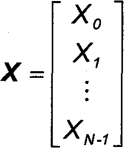 is a transmitted signal in the frequency domain and,
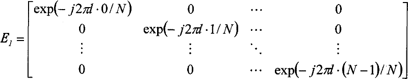 is a phase rotation matrix generated by propagation delays, an
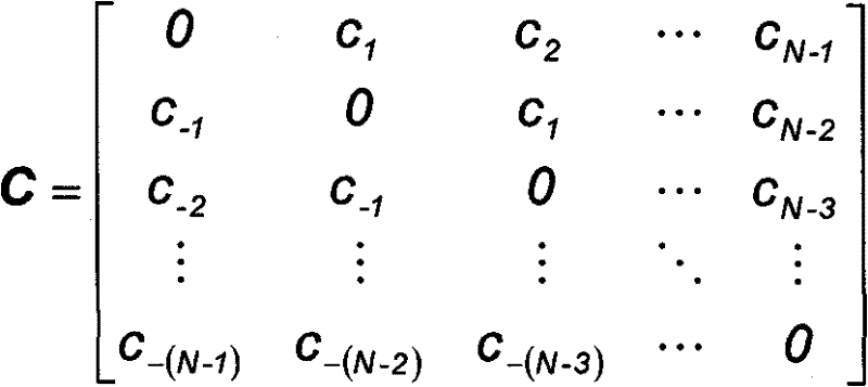 Is a matrix representing ICI, where csDescribed in equation 9. As can be derived from the attached appendix a,
Where T is the rank number (rank number) used to describe ICI. The larger T, the more accurate equation 11 will be. Thus, equation 11 can be rewritten as:
Wherein h ist(l) Non-fixed variables, including the channel impulse response and doppler frequency offset of the corresponding segment,

and matrix C of one pathtEl(0. ltoreq. T. ltoreq.T) is the progression extension of ICI, T is the rank of the progression. Typically, the variable corresponding to the low rank matrix is larger than the variable corresponding to the high rank matrix, i.e., ht1(l)>ht2(l)(t1<t2)。
All segments of the doppler spread are combined to obtain the actual channel model. Matrix CtAnd ElIs fixed, only matrix ht(l) Varying with segmentation. Thus, the format of the proposed channel model over the entire doppler spread is the same as equation 12, with the only difference being ht(l)。
In order to describe the channel characteristics using equation 12, (h) must be estimatedt(l) Total of (L +1) (T +1) variables. Providing only a basic linear estimation algorithm as how to obtain the variable ht(l) Examples of (2). The linear estimation algorithm can be used to estimate the variables if one OFDM symbol includes (L +1) (T +1) pilot signals (or more). An example of a basic linear estimation scheme is described below.
The transmit data is zeroed to construct:
X=[P0 0 ... 0 P1 0 ... 0 ... P(L+1)(T+1)-1]T,
wherein, PsIs a pilot signal.]TIs a transpose operator. Correspondingly, the received pilot signal in the frequency domain is:
Y=[y0 0 ... 0 y1 0 ... 0 ... y(L+1)(T+1)-1]T
substituting X and Y into the equations yields (L +1) (T +1) equations. The variables are then obtained by solving these linear equations, which implies low processing delay and achievable performance, especially under high SNR conditions.
The above channel model has two problems:
pilot overload, i.e., at least (L +1) (T +1) pilots are required in one OFDM symbol, which reduces transmission efficiency (especially when the number of subcarriers allocated to one user is small); and
even with the Minimum Mean Square Error (MMSE) algorithm, the linear channel estimation operation increases the gaussian noise power level and makes estimation difficult (especially under low SNR conditions).
As shown in equation 12, the iterative channel estimation scheme for ICI cancellation in a multi-carrier system employs the above-described channel model including a plurality of fixed matrices and non-fixed variables, in which a total of (L +1) (T +1) variables (h) are estimatedt(l))。
Given this channel model, and further assuming that one OFDM symbol includes (L +1) (T +1) pilot signals (or more), the iterative channel estimation scheme and corresponding pilot allocation scheme allows for accurate estimation of the channel response without significantly increasing the gaussian noise power level.
With respect to the channel model, exemplary embodiments of the present invention iteratively perform the above-described channel estimation as described in a provisional application entitled "An iterative channel estimation scheme for ICI cancellation in multi-carrier systems" filed concurrently by the same inventors, the entire contents of which are incorporated herein by reference. Considering that the matrix of a path is a series expansion of ICI, the non-fixed variables corresponding to low rank matrices are usually larger than those corresponding to high rank matrices. Thus, the variables corresponding to the lowest rank matrix for each path are first estimated, and then the contribution of this lowest rank matrix to the received signal is removed. By treating the iterative operation as a "round" and repeating the operation as a series of "rounds", all variables can be estimated to finally obtain the channel estimate.
In addition, in order to reduce the correlation between different paths, the invention can adopt an associated pilot frequency allocation method.
A detailed description of the iterative channel estimation method is now provided.
In the first pass, h is estimated according to the following equation0(l)(0≤l≤L):
Wherein, XpIs a transmitted pilot signal in the frequency domain (the signal of the data part is set to zero), YpIs the received pilot signal in the frequency domain (the signal of the data part is set to zero). Only if the number of pilots exceeds L, pair h can be determined by solving equation 13 (e.g., via ZF, MMSE, etc.)0(l) Is estimated by
In the second round, the estimated contribution to the first rank is removed, and equation 13 is rewritten as:
Then, it can be determined by solving equation 14
The second round of operation is repeatedly solved (iterated) until variables with higher rank are obtained.
Distributed resource allocation schemes can fully exploit the advantages of frequency diversity compared to localized allocation. However, distributed allocation schemes are more sensitive to ICI resulting from asynchrony between multiple UEs. That is, the target UE's signal is interfered not only by its own signal (self-interference), but also by signals from other UEs in simultaneous Uplink (UL) transmission. Asynchrony may come from several sources, for example, sampling frequency error, carrier frequency error, and doppler frequency offset.
For distributed resource allocation, this interference sometimes becomes very severe and results in the detection of an "Error Floor".
The present invention provides an equalization scheme for UL transmission, a detection scheme based on the above channel model, and an iterative channel estimation scheme to overcome this ICI.
Based on the above channel model, the received signal is described as the product of the transmitted signal and a channel characterization matrix, which includes channel parameters and ICI from multiple UEs. The channel parameters are obtained, for example, by the iterative channel estimation scheme described above or other equivalent schemes. The simplified method of the present invention then provides the inverse channel characterization matrix. Channel equalization may then be performed according to known conventional algorithms (e.g., zero-forcing ZF and MMSE).
The present invention is described by first introducing an example of the distributed resource allocation scheme of the present invention and then detailing the equalization scheme of the present invention based on this example.
Assuming that three (3) UEs share the entire bandwidth, then fig. 4 illustrates a distributed resource allocation diagram.
According to the above channel model, the received signal in a multi-user system can be described as:
Wherein, XiIs the transmission signal of the ith UE in the frequency domain (the positions of the signals of the other UEs are set to zero), X is the integral of the transmission signals of all UEs in the frequency domain, Y is the integral of the reception signals of all UEs in the frequency domain, ht i(l) Is the channel response of the ith UE, Ct iAnd El iIs for the ith UE and comprises a first node BtAnd El(CtAnd ElAs described above) of the fixed matrix including the column vectors extracted in (b):
c corresponding to the signal position of the ith UEt iAnd El iColumn vector of (2) and CtAnd ElAre the same for the corresponding column vectors of
When the column index does not match the position of the signal of the ith UE, C is addedt iAnd El iThe column vector of (a) is set to zero.
When h is paired according to the iterative channel estimation scheme described abovet i(l) When the estimation is performed, the transmission signal is restored according to equation 16.
Where U is the number of UEs, f ((A + B)-1) Is determined by the equalization algorithm (e.g., ZF, MMSE, etc.) (A + B)-1As a function of (c). However, regardless of the algorithm utilized, the inverse of (A + B) must be determined.
Obtaining the inverse of the matrix typically incurs significant computational cost, particularly for large FFT sizes, and thus the present invention provides a technique for obtaining the inverse matrix with lower complexity. Considering ht i(l) Generally decreasing with increasing t, the simplified algorithm is described below:
Since A is a diagonal matrix, A is-1It is easy to calculate and the larger T, the more accurate equation 17 will be.
Based on equation 17, MMSE is taken as an example only to show how to equalize the received signal:
Wherein
C=E+A-1A-H
Since C is a diagonal matrix, and generally C is greater than D, (C + D) can be determined using the method described above for equation 17-1。
Using equations 17 and 18, equalization is performed via a matrix multiplication operation instead of a matrix inversion operation, which can significantly drive the computational complexity from o (n)3) Down to o (n)1.5)。
The provided scheme can be applied to multi-carrier systems (e.g., OFDM, SC-FDMA, MC-CDMA, etc.) and is particularly effective in high mobility environments.
Referring now to fig. 5, an exemplary embodiment of an OFDM system according to the present invention is illustrated, wherein the receiver comprises means for implementing an equalization scheme for distributed resource allocation in a multi-carrier system, schematically illustrated by blocks E501, SIM 502 and EQ 503. In the present invention, the OFDM system transmits a block with N symbols, where the shape and size of the block processed at reception is not fixed in order to make the block size best match the system architecture.
The object of the present invention is to detect multiple users for distributed resource allocation in a multi-carrier system through the process disclosed above and implemented by modules E501, SIM 502 and EQ 503. In an exemplary embodiment, this is done by transmitting a pilot signal with the signal of the data part set to zero and the OFDM receiver of fig. 5, which demodulates the received pilot signal using the fast fourier transform 102, and then the estimation block E501 iteratively calculates and removes ICI until rank T is included by calculating equation 13 for the first round of iterations and equation 14 for the remaining rounds of iterations. Other iterative methods may be used to determine the channel characteristics matrix a and the matrix B characterizing the ICI from multiple UEs. Then, since a is a diagonal matrix, the SIM 502 inverts the determined channel characteristic matrix a by simplifying the inversion module, and calculates equation 17. Finally, equalization is performed by equalization module EQ503 using known techniques and the transmitted signal is estimated using equation 16.
While exemplary embodiments of the invention have been provided, it will be appreciated by those skilled in the art that the invention is not limited to the specific details and exemplary embodiments shown and described herein. Accordingly, various modifications may be made without departing from the spirit or scope of the general inventive concept as defined by the appended claims and their equivalents.
Claims (17)
1. A method of equalisation for distributed resource allocation in a multi-carrier system, the multi-carrier system having a plurality of user equipments, UEs, the method comprising:
defining a channel model, wherein a received signal is described as a product of a transmitted signal and a channel characterization matrix comprising channel parameters and a matrix characterizing ICI from the plurality of UEs;
obtaining a channel feature matrix including channel parameters and ICI by a channel estimation device based on the defined channel model;
inverting the obtained channel characteristic matrix through a simplifying device so as to invert a channel response matrix; and
channel equalization is performed according to a known equalization algorithm.
2. The method as claimed in claim 1, wherein the channel estimation apparatus performs an iterative estimation process of an iterative linear channel estimation process in which only pilot signals are transmitted without transmitting data signals, and uses the received pilot signals to adopt equation Yp=(A+B)XpEstimating a channel characteristics matrix A and a matrix B for ICI from a plurality of UEs, wherein XpIs a transmitted pilot signal in the frequency domain, YpIs a received pilot signal in the frequency domain.
3. The method of claim 1, wherein the simplified inverting means is a product of T expressions.
4. The method of claim 3, wherein the channel characterization matrix comprises two matrices: part I is a including a plurality of target signals, and part II is B including an ICI part.
5. The method of claim 4, wherein the first component of the T expression products is the inverse of part I ═ A-1。
6. The method of claim 5 wherein the other components of the product of the T expressions are represented by the identity matrix in the following equation representing the product of the T expressions, the inverse of part I ═ A-1And matrix part II ═ B:
7. the method of claim 6, wherein the transmitted signal is recovered using a matrix of part I-a and part II-B based on a defined channel model, and the following equation in which the received signal in a multi-user system is described as:
where U is the number of UEs, XiIs the transmission signal of the ith UE in the frequency domain, the positions of the signals of the other UEs are set to zero, X is the integral of the transmission signals of all UEs in the frequency domain, Y is the integral of the reception signals of all UEs in the frequency domain, ht i(l) Is the channel response of the ith UE,and, Ct iAnd El iIs a fixed matrix for the ith UE comprising an ICI matrix C from the ICI matrix according to a predetermined selection criteriontAnd a phase rotation matrix ElThe extracted column vector.
8. The method of claim 9, wherein the predetermined selection criteria comprises:
c corresponding to the signal position of the ith UEt iAnd El iColumn vector of (2) and CtAnd ElAre the same for the corresponding column vectors of
When the column index does not match the position of the signal of the ith UE, C is addedt iAnd El iThe column vector of (a) is set to zero.
9. The method according to claim 8, wherein the known equalization algorithm is selected from the group consisting of zero-forcing ZF and minimum mean square error, MMSE.
10. The method according to claim 1, wherein the known equalization algorithm is selected from the group consisting of zero-forcing ZF and minimum mean square error, MMSE.
11. The method according to claim 2, wherein the known equalization algorithm is selected from the group consisting of zero-forcing ZF and minimum mean square error, MMSE.
12. An equalization system for distributed resource allocation in a multi-carrier system, the multi-carrier system having a plurality of user equipments, UEs, the method comprising:
channel estimation means for obtaining a channel characteristic matrix a including channel parameters and a matrix B characterizing ICI from a plurality of UEs such that a received signal is Y ═ (a + B) X;
simplified means for using A-1And the following equation inverts the matrix A + B to obtain (A + B)-1:
a channel equalization module for using the inverted channel characteristic matrix A according to a known equalization algorithm-1To perform equalization to estimate the transmission signal X ═ f ((a + B)-1)Y。
13. The system as in claim 12, wherein the known equalization algorithm is selected from the group consisting of zero-forcing ZF and minimum mean square error, MMSE.
14. The system of claim 12, wherein the channel estimation means performs an iterative linear channel estimation process in which only pilot signals are transmitted and no data signals are transmitted, and equation Y is employed using the received pilot signalsp=(A+B)XpTo estimate a channel characteristics matrix a and a matrix B of ICI from multiple UEs, where X ispIs a transmitted pilot signal in the frequency domain, YpIs a received pilot signal in the frequency domain.
15. The system as in claim 14, wherein the known equalization algorithm is selected from the group consisting of zero-forcing ZF and minimum mean square error, MMSE.
16. The method of claim 15, wherein the transmitted signal is recovered using a matrix of part I-a and part II-B based on a defined channel model, and the following equation in which the received signal in a multi-user system is described as:
where U is the number of UEs, XiIs the transmission signal of the ith UE in the frequency domain, the positions of the signals of the other UEs are set to zero, X is the integral of the transmission signals of all UEs in the frequency domain, Y is the integral of the reception signals of all UEs in the frequency domain, ht i(l) Is the channel response of the ith UE, and Ct iAnd El iIs a fixed matrix for the ith UE comprising a selection from the ICI matrix C according to a predetermined selection criteriontAnd a phase rotation matrix ElThe extracted column vector.
17. The method of claim 16, wherein the predetermined selection criteria comprises:
c corresponding to the signal position of the ith UEt iAnd El iColumn vector of (2) and CtAnd ElAre the same for the corresponding column vectors of
When the column index does not match the position of the signal of the ith UE, C is addedt iAnd El iThe column vector of (a) is set to zero.
Applications Claiming Priority (1)
| Application Number | Priority Date | Filing Date | Title |
|---|---|---|---|
| PCT/CN2008/001421 WO2010015103A1 (en) | 2008-08-04 | 2008-08-04 | A simplified equalizationscheme for distributed resource allocation in multi-carrier systems |
Publications (1)
| Publication Number | Publication Date |
|---|---|
| CN102113285A true CN102113285A (en) | 2011-06-29 |
Family
ID=41663266
Family Applications (1)
| Application Number | Title | Priority Date | Filing Date |
|---|---|---|---|
| CN200880130618.2A Pending CN102113285A (en) | 2008-08-04 | 2008-08-04 | A simplified equalizationscheme for distributed resource allocation in multi-carrier systems |
Country Status (4)
| Country | Link |
|---|---|
| US (1) | US8411773B2 (en) |
| EP (1) | EP2311232A4 (en) |
| CN (1) | CN102113285A (en) |
| WO (1) | WO2010015103A1 (en) |
Cited By (2)
| Publication number | Priority date | Publication date | Assignee | Title |
|---|---|---|---|---|
| WO2013056521A1 (en) * | 2011-10-19 | 2013-04-25 | 上海炜呈智能电力科技有限责任公司 | Power line communication device based on channel recognition technology |
| CN103647741A (en) * | 2013-12-19 | 2014-03-19 | 电子科技大学 | Subcarrier Index Modulation (SIM)-Orthogonal Frequency Division Multiplexing (OFDM) based superposition coded modulation method |
Families Citing this family (5)
| Publication number | Priority date | Publication date | Assignee | Title |
|---|---|---|---|---|
| US8130864B1 (en) * | 2007-04-03 | 2012-03-06 | Marvell International Ltd. | System and method of beamforming with reduced feedback |
| EP2360882B1 (en) * | 2010-02-15 | 2013-05-29 | ST-Ericsson SA | Process for suppressing intercarrier interference in a OFDM receiver |
| CN107251618B (en) * | 2015-01-16 | 2021-05-14 | 梁平 | Beamforming in a multi-user multiple-input multiple-output wireless communication system with repeaters |
| US10826728B2 (en) | 2016-08-12 | 2020-11-03 | Cohere Technologies, Inc. | Localized equalization for channels with intercarrier interference |
| US12483443B2 (en) * | 2021-05-21 | 2025-11-25 | Lenovo (Singapore) Pte. Ltd. | Determining a magnitude of a composite zero-forcing equalizer |
Family Cites Families (13)
| Publication number | Priority date | Publication date | Assignee | Title |
|---|---|---|---|---|
| AU4238697A (en) * | 1996-08-29 | 1998-03-19 | Cisco Technology, Inc. | Spatio-temporal processing for communication |
| JP2003524338A (en) | 2000-02-22 | 2003-08-12 | コーニンクレッカ フィリップス エレクトロニクス エヌ ヴィ | Multi-channel receiver with channel estimator |
| US6647078B1 (en) | 2000-06-30 | 2003-11-11 | Motorola, Inc. | Method and device for multi-user frequency-domain channel estimation based on gradient optimization techniques |
| EP1364506A2 (en) * | 2001-02-22 | 2003-11-26 | Koninklijke Philips Electronics N.V. | Multicarrier transmission system with reduced complexity channel response estimation |
| JP4164363B2 (en) | 2001-02-22 | 2008-10-15 | コーニンクレッカ フィリップス エレクトロニクス エヌ ヴィ | Reduced complexity intercarrier interference cancellation |
| US7099377B2 (en) | 2002-04-03 | 2006-08-29 | Stmicroelectronics N.V. | Method and device for interference cancellation in a CDMA wireless communication system |
| US20040005010A1 (en) | 2002-07-05 | 2004-01-08 | National University Of Singapore | Channel estimator and equalizer for OFDM systems |
| WO2005117381A1 (en) | 2004-05-28 | 2005-12-08 | Koninklijke Philips Electronics N.V. | A method for signal processing and a signal processor in an ofdm system |
| US20080008261A1 (en) | 2004-05-28 | 2008-01-10 | Koninklijke Philips Electronics, N.V. | Method for Signal Processing and a Signal Processor in an Ofdm System |
| CN1750527A (en) * | 2004-09-17 | 2006-03-22 | 上海无线通信研究中心 | Signal equalizing method in orthogonal frequency division multiplex system |
| JP2009527182A (en) | 2006-02-16 | 2009-07-23 | エージェンシー フォー サイエンス,テクノロジー アンド リサーチ | Data signal processing method, data processing unit, and computer program product |
| CN102113286B (en) | 2008-08-04 | 2014-06-18 | Nxp股份有限公司 | Iterative channel estimation method and apparatus for ICI cancellation in multi-carrier systems |
| US8811505B2 (en) | 2008-08-04 | 2014-08-19 | Nxp, B.V. | Radio channel model for ICI cancellation in multi-carrier systems |
-
2008
- 2008-08-04 CN CN200880130618.2A patent/CN102113285A/en active Pending
- 2008-08-04 EP EP08783610.2A patent/EP2311232A4/en not_active Withdrawn
- 2008-08-04 US US13/057,276 patent/US8411773B2/en not_active Expired - Fee Related
- 2008-08-04 WO PCT/CN2008/001421 patent/WO2010015103A1/en not_active Ceased
Cited By (2)
| Publication number | Priority date | Publication date | Assignee | Title |
|---|---|---|---|---|
| WO2013056521A1 (en) * | 2011-10-19 | 2013-04-25 | 上海炜呈智能电力科技有限责任公司 | Power line communication device based on channel recognition technology |
| CN103647741A (en) * | 2013-12-19 | 2014-03-19 | 电子科技大学 | Subcarrier Index Modulation (SIM)-Orthogonal Frequency Division Multiplexing (OFDM) based superposition coded modulation method |
Also Published As
| Publication number | Publication date |
|---|---|
| US8411773B2 (en) | 2013-04-02 |
| WO2010015103A8 (en) | 2011-03-10 |
| WO2010015103A1 (en) | 2010-02-11 |
| US20110135019A1 (en) | 2011-06-09 |
| EP2311232A4 (en) | 2015-05-20 |
| EP2311232A1 (en) | 2011-04-20 |
Similar Documents
| Publication | Publication Date | Title |
|---|---|---|
| Hashimoto et al. | Channel estimation and equalization for CP-OFDM-based OTFS in fractional Doppler channels | |
| US6826240B1 (en) | Method and device for multi-user channel estimation | |
| CN101601244B (en) | Transmission/reception methods and modules for a multiple-carrier multiple-antenna system with training sequence | |
| EP2605463B1 (en) | Propagation path estimation method and apparatus | |
| US8374266B2 (en) | Iterative channel estimation method and apparatus for ICI cancellation in multi-carrier | |
| EP1473862B1 (en) | Apparatus and method for transmitting training symbol groups in an OFDM communications system using multiple antennas | |
| JP4198428B2 (en) | Wireless transmission device | |
| US6990153B1 (en) | Method and apparatus for semi-blind communication channel estimation | |
| CN102113285A (en) | A simplified equalizationscheme for distributed resource allocation in multi-carrier systems | |
| CN102113253B (en) | Radio channel model for ici cancellation in multi-carrier systems | |
| Wei et al. | SDR system design and implementation on delay-Doppler communications and sensing | |
| JP5093343B2 (en) | MIMO receiving apparatus and method | |
| CN101247375A (en) | A method and device for carrier frequency offset estimation | |
| US7961824B2 (en) | Receiver apparatus | |
| US7450490B2 (en) | Channel estimation using the guard interval of a multicarrier signal | |
| CN102487364B (en) | Channel estimation method and apparatus thereof | |
| Thabet et al. | Synchronization error reduction using guard-band allocation for wireless communication systems | |
| US20060251037A1 (en) | Apparatus and method for performance improvement of channel estimation in broadband wireless access communication system | |
| WO2012035345A2 (en) | Improvements in ofdm communication systems | |
| Nyongesa et al. | Doppler shift estimation and compensation in high speed MIMO-OFDM VANETs | |
| Kumari et al. | Greedy Sparse Channel Estimation Framework for Multi-User OTFS Systems | |
| Aboutorab et al. | Channel estimation and ICI cancellation for high mobility pilot-aided MIMO-OFDM systems | |
| Kapoor et al. | Channel Estimation based on Kalman Filtering with BER Reduction in MIMO-OFDM Systems | |
| CN101141428A (en) | Pilot Coding and Decoding Method and Device in Orthogonal Frequency Division Multiplexing System | |
| KR20180027300A (en) | Communication apparatus and method for controlling interference in communication system |
Legal Events
| Date | Code | Title | Description |
|---|---|---|---|
| C06 | Publication | ||
| PB01 | Publication | ||
| C10 | Entry into substantive examination | ||
| SE01 | Entry into force of request for substantive examination | ||
| C02 | Deemed withdrawal of patent application after publication (patent law 2001) | ||
| WD01 | Invention patent application deemed withdrawn after publication |
Application publication date: 20110629 |