CN102104560A - Channel estimation method and device - Google Patents
Channel estimation method and device Download PDFInfo
- Publication number
- CN102104560A CN102104560A CN2011100785554A CN201110078555A CN102104560A CN 102104560 A CN102104560 A CN 102104560A CN 2011100785554 A CN2011100785554 A CN 2011100785554A CN 201110078555 A CN201110078555 A CN 201110078555A CN 102104560 A CN102104560 A CN 102104560A
- Authority
- CN
- China
- Prior art keywords
- filtering
- noise reduction
- filter
- domain dimension
- wiener
- Prior art date
- Legal status (The legal status is an assumption and is not a legal conclusion. Google has not performed a legal analysis and makes no representation as to the accuracy of the status listed.)
- Granted
Links
Images


Landscapes
- Noise Elimination (AREA)
Abstract
本发明公开了一种信道估计方法和装置,计算各个导频位置的信道系数,针对各个导频位置的信道系数进行降噪滤波,利用降噪滤波输出值进行维纳滤波,得到信道估计值。利用本发明,可以在低信噪比下,提高通过维纳滤波得出的信道估计值的准确度。
The invention discloses a channel estimation method and device. The channel coefficients of each pilot position are calculated, the channel coefficients of each pilot position are subjected to noise reduction filtering, and the output value of the noise reduction filter is used to perform Wiener filtering to obtain channel estimation values. The present invention can improve the accuracy of channel estimation value obtained through Wiener filtering under low signal-to-noise ratio.
Description
技术领域technical field
本发明涉及通信技术领域,特别涉及一种信道估计方法及装置。The present invention relates to the field of communication technologies, in particular to a channel estimation method and device.
背景技术Background technique
在长期演进(LTE,Long Term Evolution)系统中,物理层的系统结构如图1所示。在发射端将信源信号依次进行编码、调制、映射成帧、快速傅里叶逆变换(IFFT,Inverse Fast Fourier Transform)和加循环前缀(CP,CyclicPrefix)的操作,然后通过信道传输给接收端。在接收端,对接收信号依次进行去CP、快速傅里叶变换(FFT,Fast Fourier Transform)、数据抽取、信道估计、均衡、解调和译码操作。随着网络技术的发展,对传输速率提出了越来越高的要求,因此图1中所示的信道估计的性能显得尤为重要。In the Long Term Evolution (LTE, Long Term Evolution) system, the system structure of the physical layer is shown in FIG. 1 . At the transmitting end, the source signal is sequentially encoded, modulated, mapped into frames, inverse fast Fourier transform (IFFT, Inverse Fast Fourier Transform) and cyclic prefix (CP, CyclicPrefix) are added, and then transmitted to the receiving end through the channel . At the receiving end, de-CP, Fast Fourier Transform (FFT, Fast Fourier Transform), data extraction, channel estimation, equalization, demodulation and decoding operations are performed on the received signal in sequence. With the development of network technology, higher and higher requirements are placed on the transmission rate, so the performance of channel estimation shown in Figure 1 is particularly important.
现有技术中的信道估计方法由以下两个步骤实现:The channel estimation method in the prior art is realized by the following two steps:
步骤1:估计导频(pilot)位置的信道系数。Step 1: Estimate channel coefficients at pilot positions.
导频符号由发射端插入到发射信号中的固定位置,对于接收端来说,这些固定位置是已知的,称为导频位置。图2为现有正方形导频符号的分布结构示意图,横坐标表示时间方向,纵坐标表示频率方向,Nc表示子载波个数,Ns表示包含的符号数,Nf表示导频符号在频率方向的间距,Nt表示导频符号在时间方向的间距,其中的黑色实心方块就是导频符号所在的导频位置。Pilot symbols are inserted into fixed positions in the transmitted signal by the transmitting end, and these fixed positions are known to the receiving end, called pilot positions. Figure 2 is a schematic diagram of the distribution structure of the existing square pilot symbols. The abscissa indicates the time direction, the ordinate indicates the frequency direction, N c indicates the number of subcarriers, N s indicates the number of symbols included, and N f indicates the frequency of the pilot symbols. The spacing in the direction of , N t represents the spacing of the pilot symbols in the time direction, where the black solid square is the pilot position where the pilot symbols are located.
本步骤中计算导频位置的信道系数的计算公式一如下:
上述公式一中的信号能量归一化|Sl′,k′|2=1,l′和k′分别代表导频位置的时域符号索引和频域符号索引,Rl′,k′代表导频位置(l′,k′)的接收信号,
步骤2:利用各个导频位置的信道系数进行维纳滤波,得到任意时频位置的信道估计值。Step 2: Wiener filtering is performed using the channel coefficients at each pilot position to obtain channel estimates at any time-frequency position.
本步骤中以2D维纳滤波为例,即这里执行的是二维内插滤波,计算公式二如下:In this step, 2D Wiener filtering is taken as an example, that is, two-dimensional interpolation filtering is performed here, and the calculation formula 2 is as follows:
上述公式二中的data集合中的个数为D=NcNs,wl′,k′,l,k为二维维纳滤波器的滤波系数,(l′,k′)∈Γl,k表示估计区域中的导频资源集合,如图2所示,估计区域中包括交叉实线连接的四个导频位置。The number of data sets in the above formula 2 is D=N c N s , w l', k', l, k is the filter coefficient of the two-dimensional Wiener filter, (l', k')∈Γ l , k represents the set of pilot resources in the estimation area, as shown in Figure 2, the estimation area includes four pilot positions connected by cross solid lines.
上述步骤2可以进行多次,每次利用一个估计区域中的导频位置的信道系数,得出该估计区域中的任意时频位置的信道估计值,例如图2中的斜线阴影区域就代表两条交叉实线所连接的4个导频位置限定的估计区域内的一个时频位置的信道估计值。The above step 2 can be performed multiple times, each time using the channel coefficient of the pilot position in an estimation area to obtain the channel estimation value of any time-frequency position in the estimation area, for example, the shaded area in Figure 2 represents The channel estimation value of a time-frequency position within the estimation area defined by the 4 pilot positions connected by two crossing solid lines.
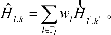
上述步骤2中同样也可以使用1D维纳滤波得出任意时频位置的信道估计值,这时需分别进行时域维度和频域维度的插值滤波,其中时域维度插值滤波的计算公式三为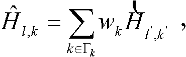
在现有技术中的信道估计方法中,在步骤2中有如下两种维纳滤波的实现方式:In the channel estimation method in the prior art, there are two implementations of Wiener filtering in step 2 as follows:
第一、采用2级1D维纳滤波,或者采用1级2D维纳滤波。这样得出的结果与理想信道估计的差距较小,但是计算量较大,复杂程度较高。First, a 2-stage 1D Wiener filter is used, or a 1-stage 2D Wiener filter is used. The difference between the result obtained in this way and the ideal channel estimation is small, but the calculation amount is large and the complexity is high.
第二、采用1级1D维纳滤波。这种滤波方式虽然计算量较小,但是在低信噪比(SNR,Signal to Noise Ratio)下,与理想信道估计值的差距较大。Second, a 1-level 1D Wiener filter is used. Although this filtering method has a small amount of calculation, it has a large gap with the ideal channel estimation value under low signal-to-noise ratio (SNR, Signal to Noise Ratio).
发明内容Contents of the invention
本发明实施例提供一种信道估计方法和装置,可以在低SNR下,提高通过维纳滤波得出的信道估计值的准确度。Embodiments of the present invention provide a channel estimation method and device, which can improve the accuracy of channel estimation values obtained through Wiener filtering under low SNR conditions.
一种信道估计方法,包括:A channel estimation method, comprising:
计算各个导频位置的信道系数;Calculating channel coefficients for each pilot position;
针对所述各个导频位置的信道系数进行降噪滤波,得到降噪滤波输出值;Performing noise reduction filtering on the channel coefficients of each pilot position to obtain an output value of noise reduction filtering;
利用所述降噪滤波输出值进行维纳滤波,得到信道估计值。Using the output value of the noise reduction filter to perform Wiener filtering to obtain a channel estimation value.
一种信道估计装置,包括:A channel estimation device, comprising:
信道系数模块,用于计算各个导频位置的信道系数、并输出给降噪模块;The channel coefficient module is used to calculate the channel coefficient of each pilot position and output it to the noise reduction module;
降噪模块,用于针对所述各个导频位置的信道系数进行降噪滤波,得到降噪滤波输出值、并输出给维纳滤波模块;A noise reduction module, configured to perform noise reduction filtering on the channel coefficients of each pilot position, obtain an output value of the noise reduction filter, and output it to the Wiener filter module;
维纳滤波模块,用于利用所述降噪滤波输出值进行维纳滤波,得到信道估计值。The Wiener filtering module is configured to use the output value of the noise reduction filter to perform Wiener filtering to obtain a channel estimation value.
可见,本发明实施例中的信道估计方法和装置中,由于维纳滤波利用的是降噪滤波输出值,而降噪滤波输出值又是由若干导频位置的信道系数得出,所以相对于现有技术中利用导频位置的信道系数进行维纳滤波,相当于扩大了维纳滤波的滤波区域,减少了由于噪声引起的误差传递、提高了SNR,从而提升了低SNR下信道估计的准确性,即在低SNR情况下,提高了通过维纳滤波得出的信道估计值的准确度。It can be seen that in the channel estimation method and device in the embodiment of the present invention, since the Wiener filter uses the output value of the noise reduction filter, and the output value of the noise reduction filter is obtained from the channel coefficients of several pilot positions, so compared to In the prior art, the channel coefficient of the pilot position is used to perform Wiener filtering, which is equivalent to expanding the filtering area of Wiener filtering, reducing the error transmission caused by noise, and improving the SNR, thereby improving the accuracy of channel estimation under low SNR , that is, in the case of low SNR, the accuracy of the channel estimation value obtained by Wiener filtering is improved.
附图说明Description of drawings
图1为现有LTE系统中物理层的系统结构示意图;FIG. 1 is a schematic diagram of a system structure of a physical layer in an existing LTE system;
图2为现有正方形导频符号的分布结构示意图;FIG. 2 is a schematic diagram of a distribution structure of an existing square pilot symbol;
图3为本发明实施例中的信道估计方法流程图;FIG. 3 is a flowchart of a channel estimation method in an embodiment of the present invention;
图4为本发明的应用实例中信道估计方法流程图;Fig. 4 is the flow chart of channel estimation method in the application example of the present invention;
图5为本发明实施例中的信道估计装置的结构示意图;FIG. 5 is a schematic structural diagram of a channel estimation device in an embodiment of the present invention;
图6为本发明实施例中降噪模块的结构示意图;FIG. 6 is a schematic structural diagram of a noise reduction module in an embodiment of the present invention;
图7为本发明实施例中降噪模块中的第一滤波器或第二滤波器的结构示意图。Fig. 7 is a schematic structural diagram of a first filter or a second filter in a noise reduction module in an embodiment of the present invention.
具体实施方式Detailed ways
为使本发明的目的和优点更加清楚,下面结合附图和实施例对本发明作进一步的详细说明。In order to make the objects and advantages of the present invention clearer, the present invention will be further described in detail below in conjunction with the accompanying drawings and embodiments.
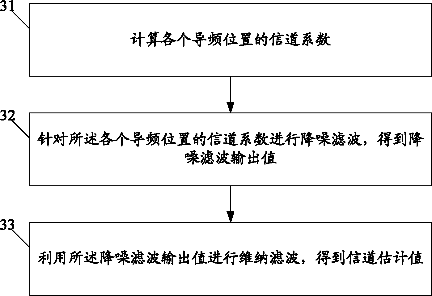
图3为本发明实施例中的信道估计方法流程图,该流程包括:FIG. 3 is a flow chart of a channel estimation method in an embodiment of the present invention, and the process includes:
步骤31:计算各个导频位置的信道系数。Step 31: Calculate the channel coefficients of each pilot position.
步骤32:针对所述各个导频位置的信道系数进行降噪滤波,得到降噪滤波输出值。Step 32: Perform noise reduction filtering on the channel coefficients at each pilot position to obtain an output value of the noise reduction filtering.
步骤33:利用所述降噪滤波输出值进行维纳滤波,得到信道估计值。Step 33: Using the output value of the noise reduction filter to perform Wiener filtering to obtain an estimated channel value.
可见,本发明实施例中的信道估计方法中,由于维纳滤波利用的是降噪滤波输出值,而降噪滤波输出值又是由若干导频位置的信道系数得出,所以相对于现有技术中利用导频位置的信道系数进行维纳滤波,相当于扩大了维纳滤波的滤波区域,减少了由于噪声引起的误差传递、提高了SNR,从而提升了低SNR下信道估计的准确性,即在低SNR情况下,提高了通过维纳滤波得出的信道估计值的准确度。It can be seen that in the channel estimation method in the embodiment of the present invention, since the Wiener filter uses the output value of the noise reduction filter, and the output value of the noise reduction filter is obtained from the channel coefficients of several pilot positions, so compared with the existing In the technology, the channel coefficient of the pilot position is used to perform Wiener filtering, which is equivalent to expanding the filtering area of Wiener filtering, reducing the error transmission caused by noise, and improving the SNR, thereby improving the accuracy of channel estimation under low SNR. That is, in the case of low SNR, the accuracy of the channel estimation value obtained through Wiener filtering is improved.
进一步,本发明实施例中的方法还降低了维纳滤波算法的复杂性,并降低了维纳滤波对导频位置的信道系数的依赖程度,提高了对维纳滤波统计参数的鲁棒性。Further, the method in the embodiment of the present invention also reduces the complexity of the Wiener filtering algorithm, reduces the dependence of the Wiener filtering on the channel coefficient of the pilot position, and improves the robustness to the statistical parameters of the Wiener filtering.
下面给出本发明实施例中的方法的一个具体应用实例,以信道估计中使用1D维纳滤波为例。A specific application example of the method in the embodiment of the present invention is given below, taking the use of 1D Wiener filtering in channel estimation as an example.
图4为本发明的应用实例中信道估计方法流程图,该流程包括:Fig. 4 is the flow chart of channel estimation method in the application example of the present invention, and this process comprises:
步骤41:计算各个导频位置的信道系数。Step 41: Calculate the channel coefficients of each pilot position.
本步骤中,按照现有技术中的公式一计算各个导频位置的信道系数。In this step, the channel coefficients of each pilot position are calculated according to Formula 1 in the prior art.
步骤42:针对第一滤波区域,利用该第一滤波区域中的导频位置的信道系数在时域维度上进行有限长单位冲激响应(FIR,Finite Impulse Response)滤波,得到时域维度上的降噪滤波输出值。Step 42: For the first filtering area, use the channel coefficient of the pilot position in the first filtering area to perform finite-length unit impulse response (FIR, Finite Impulse Response) filtering on the time domain dimension to obtain the time domain dimension Noise reduction filter output value.
本步骤中,在时域维度上进行FIR滤波的计算公式五如下:In this step, the calculation formula five for FIR filtering in the time domain dimension is as follows:
上述公式五中,H′l′,k′表示降噪滤波输出值,
第一滤波区域为一个以上,对每个第一滤波区域都按照公式五执行FIR滤波,即可以得到每个第一滤波区域的时域维度上的降噪滤波输出值。There are more than one first filtering area, and FIR filtering is performed on each of the first filtering areas according to formula 5, that is, the noise reduction filtering output value in the time domain dimension of each first filtering area can be obtained.
第一滤波区域可以根据实际应用需要设置其大小。本应用实例中,第一滤波区域中最多包含四个导频位置。The size of the first filtering region can be set according to actual application needs. In this application example, the first filtering region contains at most four pilot positions.
步骤43:利用时域维度上的降噪滤波输出值进行时域维度的1D维纳滤波,利用导频位置的信道系数进行频域维度的1D维纳滤波,得到信道估计值。Step 43: Use the output value of the noise reduction filter in the time domain dimension to perform 1D Wiener filtering in the time domain dimension, and use the channel coefficient at the pilot position to perform 1D Wiener filtering in the frequency domain dimension to obtain an estimated channel value.
本步骤中,在频域维度上的1D维纳滤波与现有技术中的方法完全一样,在时域维度上的1D维纳滤波与现有技术中的方法类似,仅需将现有技术公式中的导频位置的信道系数替换为步骤42中各个第一滤波区域的时域维度上的降噪滤波输出值即可。In this step, the 1D Wiener filtering in the frequency domain dimension is exactly the same as the method in the prior art, and the 1D Wiener filtering in the time domain dimension is similar to the method in the prior art, only the prior art formula The channel coefficients at the pilot positions in are replaced by the noise reduction filter output values in the time domain dimension of each first filter region in step 42 .
除了以上应用实例中举出的情况外,第一滤波区域中包括的最大导频位置数量还可以设置为除四个之外的其他值,这里的数量设定主要依据具体应用场景下执行降噪滤波的滤波器的能力,在该滤波器的能力值范围内可以设置尽可能大的值。In addition to the cases mentioned in the above application examples, the maximum number of pilot positions included in the first filtering area can also be set to other values other than four, and the number setting here is mainly based on the implementation of noise reduction in specific application scenarios Filtering ability of the filter, within the range of the ability value of the filter can be set as large as possible.
上述步骤42中还可以在频域维度上进行FIR滤波,其中在频域维度上进行的FIR滤波所依据的公式与公式五相同,只是w(i)的生成方式不同,具体生成方式属于现有技术。在此基础上,步骤43中在时域维度上的1D维纳滤波与现有技术中的方法完全一样,在频域维度上的1D维纳滤波与现有技术中的方法类似,仅需将现有技术公式中的导频位置的信道系数替换为步骤42中各个第一滤波区域的频域维度上的降噪滤波输出值即可。In the above-mentioned step 42, FIR filtering can also be performed on the frequency domain dimension, wherein the formula based on the FIR filtering performed on the frequency domain dimension is the same as formula five, except that the generation method of w(i) is different, and the specific generation method belongs to the existing technology. On this basis, the 1D Wiener filtering in the time domain dimension in step 43 is exactly the same as the method in the prior art, and the 1D Wiener filtering in the frequency domain dimension is similar to the method in the prior art, only need to The channel coefficient of the pilot position in the formula of the prior art may be replaced by the noise reduction filter output value in the frequency domain dimension of each first filter area in step 42 .
上述步骤42还可以在时域维度和频域维度上都进行FIR滤波,假设先进行时域维度、再进行频域维度上的FIR滤波,则先针对第一滤波区域中的导频位置的信道系数,进行时域维度的降噪滤波,得到时域维度上的降噪滤波输出值;再针对第二滤波区域中的时域维度上的降噪滤波输出值,进行频域维度的降噪滤波,得到最终的降噪滤波输出值。假设先进行频域维度、再进行时域维度上的FIR滤波,则先针对第一滤波区域中的导频位置的信道系数,进行频域维度的降噪滤波,得到频域维度上的降噪滤波输出值;再针对第二滤波区域中的频域维度上的降噪滤波输出值,进行时域维度的降噪滤波,得到最终的降噪滤波输出值。这里的第二滤波区域为一个以上,也可以根据实际应用设置其大小,即设置第二滤波区域中最多包括几个降噪滤波输出值。在此基础上,步骤43中在时域维度和频域维度上的1D维纳滤波与现有技术中的方法类似,仅需将现有技术公式中的导频位置的信道系数替换为步骤42中得到的最终的降噪滤波值即可。The above-mentioned step 42 can also perform FIR filtering on both the time domain dimension and the frequency domain dimension. Assuming that the time domain dimension is performed first, and then the FIR filtering on the frequency domain dimension is performed, then the channel at the pilot position in the first filtering area is first Coefficients, perform noise reduction filtering in the time domain dimension to obtain the output value of the noise reduction filter in the time domain dimension; then perform noise reduction filtering in the frequency domain dimension for the output value of the noise reduction filter in the time domain dimension in the second filtering area , to get the final noise reduction filter output value. Assuming that the frequency domain dimension is performed first, and then the FIR filtering in the time domain dimension is performed, the channel coefficient of the pilot position in the first filtering area is firstly subjected to noise reduction filtering in the frequency domain dimension to obtain the noise reduction in the frequency domain dimension filtering output value; then performing noise reduction filtering in the time domain dimension on the noise reduction filtering output value in the frequency domain dimension in the second filtering region to obtain a final noise reduction filtering output value. There are more than one second filtering area here, and its size can also be set according to the actual application, that is, the second filtering area is set to include at most several noise reduction filter output values. On this basis, the 1D Wiener filtering in the time domain dimension and the frequency domain dimension in step 43 is similar to the method in the prior art, only the channel coefficient of the pilot position in the prior art formula needs to be replaced by step 42 The final noise reduction filter value obtained in
以上应用实例以1D维纳滤波为例,本发明中的方法也可以应用在2D维纳滤波中,这时,步骤42中进行时域维度和频域维度上的降噪滤波,步骤43中的2D维纳滤波与现有技术中的方法类似,仅需将现有技术公式中的导频位置的信道系数替换为步骤42中得到的最终的降噪滤波值即可。The above application examples take 1D Wiener filtering as an example, and the method in the present invention can also be applied in 2D Wiener filtering. At this time, in step 42, carry out the noise reduction filtering on the time domain dimension and the frequency domain dimension, and in step 43 The 2D Wiener filtering is similar to the method in the prior art, only need to replace the channel coefficient of the pilot position in the formula of the prior art with the final noise reduction filter value obtained in step 42 .
除了FIR滤波外,本发明实施例还可以在在时域维度和/或频域维度上进行无限长单位冲激响应(IIR,infinite impulse response)滤波,实现方式与FIR滤波相同,只是使用的计算公式相应为IIR滤波的计算公式。In addition to FIR filtering, the embodiment of the present invention can also perform infinite unit impulse response (IIR, infinite impulse response) filtering on the time domain dimension and/or frequency domain dimension. The implementation method is the same as that of FIR filtering, except that the calculation used The corresponding formula is the calculation formula of IIR filtering.
图5为本发明实施例中的信道估计装置,该装置包括:信道系数模块、降噪模块和维纳滤波模块。Fig. 5 is a channel estimation device in an embodiment of the present invention, the device includes: a channel coefficient module, a noise reduction module and a Wiener filter module.
上述信道系数模块,用于计算各个导频位置的信道系数、并输出给降噪模块。该信道系数模块具体可以是处理器,如CPU等。The above-mentioned channel coefficient module is used to calculate the channel coefficient of each pilot position and output it to the noise reduction module. Specifically, the channel coefficient module may be a processor, such as a CPU.
上述降噪模块,用于针对所述导频位置的信道系数进行降噪滤波,得到降噪滤波输出值、并输出给维纳滤波模块。该降噪模块具体可以是降噪滤波器。The noise reduction module is configured to perform noise reduction filtering on the channel coefficients at the pilot position to obtain an output value of the noise reduction filter and output it to the Wiener filter module. Specifically, the noise reduction module may be a noise reduction filter.
上述维纳滤波模块,用于利用所述降噪滤波输出值进行维纳滤波,得到信道估计值。该维纳滤波模块具体可以是维纳滤波器。The aforementioned Wiener filtering module is configured to use the output value of the noise reduction filter to perform Wiener filtering to obtain a channel estimation value. Specifically, the Wiener filter module may be a Wiener filter.
可见,本发明实施例中的信道估计装置中,由于维纳滤波利用的是降噪滤波输出值,而降噪滤波输出值又是由导频位置的信道系数得出,所以相对于现有技术中利用导频位置的信道系数进行维纳滤波,相当于扩大了维纳滤波的滤波区域,减少了由于噪声引起的误差传递、提高了SNR,从而提升了低SNR下信道估计的准确性,即在低SNR情况下,提高了通过维纳滤波得出的信道估计值的准确度。It can be seen that in the channel estimation device in the embodiment of the present invention, since the Wiener filter uses the output value of the noise reduction filter, and the output value of the noise reduction filter is obtained from the channel coefficient of the pilot position, so compared with the prior art In the Wiener filter, the channel coefficient of the pilot position is used to perform Wiener filtering, which is equivalent to expanding the filtering area of the Wiener filter, reducing the error transmission caused by noise, and improving the SNR, thereby improving the accuracy of channel estimation under low SNR, that is, In the case of low SNR, the accuracy of the channel estimate obtained by Wiener filtering is improved.
进一步,本发明实施例中的装置降低了维纳滤波算法的复杂性,并降低了维纳滤波对导频位置的信道系数的依赖程度,提高了对维纳滤波统计参数的鲁棒性。Further, the device in the embodiment of the present invention reduces the complexity of the Wiener filtering algorithm, reduces the dependence of the Wiener filtering on the channel coefficient of the pilot position, and improves the robustness to the statistical parameters of the Wiener filtering.
下面给出本发明实施例中的装置的一个具体应用实例,以信道估计中使用1D维纳滤波为例。A specific application example of the device in the embodiment of the present invention is given below, taking the use of 1D Wiener filtering in channel estimation as an example.
在本应用实例中,降噪模块包括第一滤波器和第二滤波器,图6为该降噪模块的结构示意图。第一滤波器和第二滤波器的功能有以下两种情况。In this application example, the noise reduction module includes a first filter and a second filter, and FIG. 6 is a schematic structural diagram of the noise reduction module. The functions of the first filter and the second filter have the following two cases.
第一、第一滤波器负责时域维度的降噪滤波,第二滤波器负责频域维度的降噪滤波。First, the first filter is responsible for noise reduction filtering in the time domain dimension, and the second filter is responsible for noise reduction filtering in the frequency domain dimension.
上述第一滤波器,用于在当前只进行时域维度的降噪滤波或进行时域维度和频域维度的降噪滤波时,针对预设第一滤波区域中的信道系数进行时域维度的降噪滤波,得到时域维度上的降噪滤波输出值输出给第二滤波器;在当前只进行频域维度的降噪滤波时,将所述导频位置的信道系数输出给第二滤波器。The above-mentioned first filter is used to perform time-domain filtering on the channel coefficients in the preset first filtering area when only performing noise-reduction filtering in the time-domain dimension or performing noise-reduction filtering in the time-domain and frequency-domain dimensions. Noise reduction filtering, the output value of the noise reduction filter obtained in the time domain dimension is output to the second filter; when only the noise reduction filter of the frequency domain dimension is currently performed, the channel coefficient of the pilot position is output to the second filter .
上述第二滤波器,用于在当前只进行时域维度的降噪滤波时,将时域维度上的降噪滤波输出值输出给维纳滤波模块;在当前进行时域维度和频域维度的降噪滤波时,针对预设第二滤波区域中的时域维度上的降噪滤波输出值进行频域维度的降噪滤波,得到最终的降噪滤波输出值、并输出给维纳滤波模块;在当前只进行频域维度的降噪滤波时,针对预设第一滤波区域中的导频位置的信道系数,进行频域维度的维纳滤波,得到频域维度上的降噪滤波输出值输出给维纳滤波模块。The above-mentioned second filter is used to output the output value of the noise reduction filter on the time domain dimension to the Wiener filter module when only the noise reduction filter of the time domain dimension is currently performed; During noise reduction filtering, perform noise reduction filtering in the frequency domain dimension on the noise reduction filter output value in the time domain dimension in the preset second filtering area, obtain the final noise reduction filter output value, and output it to the Wiener filter module; When currently only performing noise reduction filtering in the frequency domain dimension, Wiener filtering in the frequency domain dimension is performed on the channel coefficients of the pilot position in the preset first filtering area to obtain the output value output of the noise reduction filter in the frequency domain dimension to the Wiener filter module.
第二、第一滤波器负责频域维度的降噪滤波,第二滤波器负责时域维度的降噪滤波。Second, the first filter is responsible for noise reduction filtering in the frequency domain dimension, and the second filter is responsible for noise reduction filtering in the time domain dimension.
上述第一滤波器,用于在当前只进行频域维度的降噪滤波或进行时域维度和频域维度的降噪滤波时,针对预设第一滤波区域中的信道系数进行频域维度的降噪滤波,得到频域维度上的降噪滤波输出值输出给第二滤波器;在当前只进行时域维度的降噪滤波时,将所述导频位置的信道系数输出给第二滤波器。The above-mentioned first filter is used to perform frequency-domain filtering on the channel coefficients in the preset first filtering area when only performing noise-reduction filtering in the frequency-domain dimension or performing noise-reduction filtering in the time-domain and frequency-domain dimensions. Noise reduction filtering, the output value of the noise reduction filter obtained in the frequency domain dimension is output to the second filter; when only the noise reduction filter of the time domain dimension is currently performed, the channel coefficient of the pilot position is output to the second filter .
上述第二滤波器,用于在当前只进行频域维度的降噪滤波时,将频域维度上的降噪滤波输出值输出给维纳滤波模块;在当前进行频域维度和时域维度的降噪滤波时,针对预设第二滤波区域中的频域维度上的降噪滤波输出值进行时域维度的降噪滤波,得到最终的降噪滤波输出值、并输出给维纳滤波模块;在当前只进行时域维度的降噪滤波时,针对预设第一滤波区域中的导频位置的信道系数,进行时域维度的维纳滤波,得到时域维度上的降噪滤波输出值输出给维纳滤波模块。The above-mentioned second filter is used to output the output value of the noise reduction filter on the frequency domain dimension to the Wiener filter module when only the noise reduction filter of the frequency domain dimension is currently performed; During noise reduction filtering, perform noise reduction filtering in the time domain dimension on the noise reduction filter output value in the frequency domain dimension in the preset second filtering area, obtain the final noise reduction filter output value, and output it to the Wiener filter module; When currently only performing noise reduction filtering in the time domain dimension, Wiener filtering in the time domain dimension is performed on the channel coefficient of the pilot position in the preset first filtering area to obtain the output value output of the noise reduction filter in the time domain dimension to the Wiener filter module.
以FIR滤波为例,图7为本发明实施例降噪模块中的第一滤波器或第二滤波器的结构示意图,其中的H(i)代表公式五中的
本发明实施例中,降噪模块中还可以包括两个IIR滤波器,其工作方式与FIR滤波器相同,只是需按照IIR滤波的计算公式执行滤波。In the embodiment of the present invention, the noise reduction module may further include two IIR filters, and the working method thereof is the same as that of the FIR filter, except that the filtering needs to be performed according to the calculation formula of the IIR filter.
在本应用实例中,当降噪模块只进行时域维度的降噪滤波时,维纳滤波模块在时域维度利用降噪模块输出的降噪滤波输出值进行维纳滤波,在频域维度利用导频位置的信道系数进行维纳滤波;当降噪模块只进行频域维度的降噪滤波时,维纳滤波模块在频域维度利用降噪模块输出的降噪滤波输出值进行维纳滤波,在时域维度利用导频位置的信道系数进行维纳滤波;当降噪模块进行时域维度和频域维度的降噪滤波时,维纳滤波模块在时域维度和频域维度都利用降噪模块输出的降噪滤波输出值进行维纳滤波。In this application example, when the noise reduction module only performs noise reduction filtering in the time domain dimension, the Wiener filter module uses the noise reduction filter output value output by the noise reduction module to perform Wiener filtering in the time domain dimension, and uses The channel coefficient at the pilot position is subjected to Wiener filtering; when the noise reduction module only performs noise reduction filtering in the frequency domain dimension, the Wiener filtering module uses the noise reduction filter output value output by the noise reduction module to perform Wiener filtering in the frequency domain dimension, In the time domain dimension, the channel coefficient of the pilot position is used to perform Wiener filtering; when the noise reduction module performs noise reduction filtering in the time domain dimension and the frequency domain dimension, the Wiener filter module uses the noise reduction in both the time domain dimension and the frequency domain dimension The output value of the noise reduction filter output by the module is subjected to Wiener filtering.
本发明实施例的信道估计装置,按照本发明实施例的信道估计方法执行操作。The channel estimation apparatus in the embodiment of the present invention performs operations according to the channel estimation method in the embodiment of the present invention.
本领域普通技术人员可以理解实现上述实施例方法中的全部或部分步骤是可以通过程序来指令相关的硬件完成,所述的程序可以存储于一计算机可读存储介质中,该程序在执行时,可包括如上述各方法的实施例的流程。其中,所述的存储介质可为只读存储器(ROM,Read Only Memory)/随机存取存储器(RAM,Random Access Memory)、磁碟或光盘等。Those of ordinary skill in the art can understand that all or part of the steps in the method of the above-mentioned embodiments can be completed by instructing related hardware through a program. The program can be stored in a computer-readable storage medium. When the program is executed, It may include the processes of the embodiments of the above-mentioned methods. Wherein, the storage medium may be a read-only memory (ROM, Read Only Memory)/random access memory (RAM, Random Access Memory), a magnetic disk or an optical disk, etc.
综上所述,以上仅为本发明的较佳实施例而已,并非用于限定本发明的保护范围。凡在本发明的精神和原则之内,所作的任何修改、等同替换、改进等,均应包含在本发明的保护范围之内。To sum up, the above are only preferred embodiments of the present invention, and are not intended to limit the protection scope of the present invention. Any modifications, equivalent replacements, improvements, etc. made within the spirit and principles of the present invention shall be included within the protection scope of the present invention.
Claims (12)
Priority Applications (1)
| Application Number | Priority Date | Filing Date | Title |
|---|---|---|---|
| CN 201110078555 CN102104560B (en) | 2011-03-30 | 2011-03-30 | Channel estimation method and device |
Applications Claiming Priority (1)
| Application Number | Priority Date | Filing Date | Title |
|---|---|---|---|
| CN 201110078555 CN102104560B (en) | 2011-03-30 | 2011-03-30 | Channel estimation method and device |
Publications (2)
| Publication Number | Publication Date |
|---|---|
| CN102104560A true CN102104560A (en) | 2011-06-22 |
| CN102104560B CN102104560B (en) | 2013-10-02 |
Family
ID=44157095
Family Applications (1)
| Application Number | Title | Priority Date | Filing Date |
|---|---|---|---|
| CN 201110078555 Expired - Fee Related CN102104560B (en) | 2011-03-30 | 2011-03-30 | Channel estimation method and device |
Country Status (1)
| Country | Link |
|---|---|
| CN (1) | CN102104560B (en) |
Cited By (4)
| Publication number | Priority date | Publication date | Assignee | Title |
|---|---|---|---|---|
| CN103581065A (en) * | 2012-07-27 | 2014-02-12 | 重庆重邮信科通信技术有限公司 | Wiener filtering channel estimation method and device |
| CN104079509A (en) * | 2013-03-25 | 2014-10-01 | 华为技术有限公司 | Channel estimation method and device |
| CN104601500A (en) * | 2015-02-02 | 2015-05-06 | 华为技术有限公司 | Channel estimation method and device |
| CN105024953A (en) * | 2014-04-29 | 2015-11-04 | 普天信息技术有限公司 | Channel Coefficient Estimation Method |
Citations (3)
| Publication number | Priority date | Publication date | Assignee | Title |
|---|---|---|---|---|
| WO2000067389A1 (en) * | 1999-04-28 | 2000-11-09 | Nokia Corporation | Method of forming channel estimate, and receiver |
| CN101753491A (en) * | 2008-12-17 | 2010-06-23 | 中国科学院半导体研究所 | Channel estimation method for multi-input multi-output-orthogonal frequency-division multiplexing system |
| CN101808054A (en) * | 2010-03-26 | 2010-08-18 | 北京天碁科技有限公司 | Implementation method and device for channel estimation |
-
2011
- 2011-03-30 CN CN 201110078555 patent/CN102104560B/en not_active Expired - Fee Related
Patent Citations (3)
| Publication number | Priority date | Publication date | Assignee | Title |
|---|---|---|---|---|
| WO2000067389A1 (en) * | 1999-04-28 | 2000-11-09 | Nokia Corporation | Method of forming channel estimate, and receiver |
| CN101753491A (en) * | 2008-12-17 | 2010-06-23 | 中国科学院半导体研究所 | Channel estimation method for multi-input multi-output-orthogonal frequency-division multiplexing system |
| CN101808054A (en) * | 2010-03-26 | 2010-08-18 | 北京天碁科技有限公司 | Implementation method and device for channel estimation |
Non-Patent Citations (1)
| Title |
|---|
| 王军等: "变换域通信系统中的信道估计技术", 《电子科技大学学报》, no. 01, 31 January 2009 (2009-01-31) * |
Cited By (7)
| Publication number | Priority date | Publication date | Assignee | Title |
|---|---|---|---|---|
| CN103581065A (en) * | 2012-07-27 | 2014-02-12 | 重庆重邮信科通信技术有限公司 | Wiener filtering channel estimation method and device |
| CN104079509A (en) * | 2013-03-25 | 2014-10-01 | 华为技术有限公司 | Channel estimation method and device |
| CN104079509B (en) * | 2013-03-25 | 2017-10-17 | 华为技术有限公司 | A kind of channel estimation methods and device |
| CN105024953A (en) * | 2014-04-29 | 2015-11-04 | 普天信息技术有限公司 | Channel Coefficient Estimation Method |
| CN105024953B (en) * | 2014-04-29 | 2018-12-18 | 普天信息技术有限公司 | Channel coefficients estimation method |
| CN104601500A (en) * | 2015-02-02 | 2015-05-06 | 华为技术有限公司 | Channel estimation method and device |
| CN104601500B (en) * | 2015-02-02 | 2018-05-29 | 华为技术有限公司 | The method and apparatus of channel estimation |
Also Published As
| Publication number | Publication date |
|---|---|
| CN102104560B (en) | 2013-10-02 |
Similar Documents
| Publication | Publication Date | Title |
|---|---|---|
| CN101997807B (en) | Channel estimation method and device | |
| CN101808054B (en) | Implementation method and device for channel estimation | |
| CN103095639B (en) | Orthogonal frequency division multiplexing (OFDM) underwater acoustic communication parallel iterative inter-carrier interference (ICI) elimination method | |
| CN101888351B (en) | Channel estimation device and method | |
| CN101242388B (en) | Channel Estimation Method for High Speed Single Carrier Frequency Domain Equalized UWB System | |
| CN103269321B (en) | Based on the channel estimation methods of unique word in single-carrier frequency domain equalization system | |
| CN104486267B (en) | A SC‑FDE channel estimation method based on wavelet denoising in shortwave channel | |
| CN104410590A (en) | Short-wave OFDM (Orthogonal Frequency Division Multiplexing) interference suppression joint channel estimation method based on compressed sensing | |
| JPWO2008099734A1 (en) | Channel estimation apparatus, equalization apparatus, and estimation and equalization method thereof | |
| CN108881077A (en) | A kind of Wiener filtering channel estimation methods based on superimposed pilot | |
| CN101616104A (en) | The channel estimation methods of ofdm system and device | |
| CN114615113B (en) | A multi-symbol BEM channel estimation method that uses preamble sequences to de-noise base coefficients | |
| CN101707582A (en) | Method for estimating MIMO channel on basis of multi-phase decomposition | |
| CN102143115A (en) | Partial symmetric extension discrete Fourier transform-based channel estimation method | |
| CN102082754B (en) | OFDM (Orthogonal Frequency Division Multiplexing) channel estimation method and device | |
| KR20120049434A (en) | Method and apparatus for estimating channel | |
| CN103326966A (en) | Channel estimation method suitable for wireless local area network OFDM system | |
| CN103346983B (en) | The multiple Channel Estimation Interpolation Methods of a kind of OFDM self adaptation based on Comb Pilot | |
| CN102104560B (en) | Channel estimation method and device | |
| CN102761502B (en) | Channel estimation method of OFDM (orthogonal frequency division multiplexing) system | |
| CN102143113B (en) | Channel estimation method and device | |
| CN108768566A (en) | A kind of BEM channel estimation methods based on Wiener filtering | |
| CN103581065A (en) | Wiener filtering channel estimation method and device | |
| CN112152950B (en) | Channel estimation method and device based on sparse scattered pilot in OFDM system | |
| CN101588330A (en) | Joint channel estimation method for short-wave OFDM communication system |
Legal Events
| Date | Code | Title | Description |
|---|---|---|---|
| C06 | Publication | ||
| PB01 | Publication | ||
| C10 | Entry into substantive examination | ||
| SE01 | Entry into force of request for substantive examination | ||
| C14 | Grant of patent or utility model | ||
| GR01 | Patent grant | ||
| CF01 | Termination of patent right due to non-payment of annual fee | ||
| CF01 | Termination of patent right due to non-payment of annual fee |
Granted publication date: 20131002 Termination date: 20180330 |