CN102094314A - Cluster sticky fiber counting and cross section form analyzing system and rapid image processing method - Google Patents
Cluster sticky fiber counting and cross section form analyzing system and rapid image processing method Download PDFInfo
- Publication number
- CN102094314A CN102094314A CN 201010575699 CN201010575699A CN102094314A CN 102094314 A CN102094314 A CN 102094314A CN 201010575699 CN201010575699 CN 201010575699 CN 201010575699 A CN201010575699 A CN 201010575699A CN 102094314 A CN102094314 A CN 102094314A
- Authority
- CN
- China
- Prior art keywords
- image
- paper tape
- clamping
- counting
- viscose fiber
- Prior art date
- Legal status (The legal status is an assumption and is not a legal conclusion. Google has not performed a legal analysis and makes no representation as to the accuracy of the status listed.)
- Granted
Links
- 239000000835 fiber Substances 0.000 title claims abstract description 107
- 238000003672 processing method Methods 0.000 title claims abstract description 7
- 238000005520 cutting process Methods 0.000 claims abstract description 31
- 230000005540 biological transmission Effects 0.000 claims abstract description 17
- 238000000034 method Methods 0.000 claims abstract description 14
- 238000004458 analytical method Methods 0.000 claims abstract description 11
- 238000004364 calculation method Methods 0.000 claims abstract description 7
- 230000003044 adaptive effect Effects 0.000 claims abstract description 6
- 238000003825 pressing Methods 0.000 claims description 24
- 230000007246 mechanism Effects 0.000 claims description 15
- 238000001514 detection method Methods 0.000 claims description 9
- 230000001360 synchronised effect Effects 0.000 claims description 4
- 238000013500 data storage Methods 0.000 claims description 3
- 239000000203 mixture Substances 0.000 claims description 2
- 238000000465 moulding Methods 0.000 claims 6
- 230000006835 compression Effects 0.000 claims 1
- 238000007906 compression Methods 0.000 claims 1
- 230000008030 elimination Effects 0.000 claims 1
- 238000003379 elimination reaction Methods 0.000 claims 1
- 239000003292 glue Substances 0.000 claims 1
- 238000003706 image smoothing Methods 0.000 claims 1
- 238000005096 rolling process Methods 0.000 claims 1
- 229920000297 Rayon Polymers 0.000 abstract description 111
- 230000011218 segmentation Effects 0.000 abstract description 13
- 238000004519 manufacturing process Methods 0.000 abstract description 12
- 230000000877 morphologic effect Effects 0.000 abstract description 7
- 238000009499 grossing Methods 0.000 abstract description 3
- 239000000126 substance Substances 0.000 abstract description 3
- 230000002708 enhancing effect Effects 0.000 abstract 1
- 238000010586 diagram Methods 0.000 description 7
- 238000003384 imaging method Methods 0.000 description 7
- 230000002159 abnormal effect Effects 0.000 description 5
- 239000000853 adhesive Substances 0.000 description 4
- 230000001070 adhesive effect Effects 0.000 description 4
- 238000007689 inspection Methods 0.000 description 4
- 238000012360 testing method Methods 0.000 description 4
- 238000005286 illumination Methods 0.000 description 3
- 230000003287 optical effect Effects 0.000 description 3
- 239000002253 acid Substances 0.000 description 2
- 238000003709 image segmentation Methods 0.000 description 2
- 238000009434 installation Methods 0.000 description 2
- 239000002994 raw material Substances 0.000 description 2
- 238000000926 separation method Methods 0.000 description 2
- 239000004753 textile Substances 0.000 description 2
- 229920000742 Cotton Polymers 0.000 description 1
- 229920002522 Wood fibre Polymers 0.000 description 1
- 230000001594 aberrant effect Effects 0.000 description 1
- 230000009286 beneficial effect Effects 0.000 description 1
- 238000004043 dyeing Methods 0.000 description 1
- 230000000694 effects Effects 0.000 description 1
- 238000011179 visual inspection Methods 0.000 description 1
- 238000009941 weaving Methods 0.000 description 1
- 239000002025 wood fiber Substances 0.000 description 1
Images


Landscapes
- Treatment Of Fiber Materials (AREA)
Abstract
本发明涉及一种集束粘纤计数和断面形态分析系统及图像快速处理方法。该装置主要由集束粘纤遮光套自动制作装置、粘纤切丝装置、照明装置、具有二维移动工作台的体视显微镜和图像采集和图像处理子程序组成。所述的集束粘纤遮光套自动制作装置包括:遮光纸的传送部分、遮光纸的剪裁成型部分、夹紧部分和转动传动部分。所述的图像快速处理方法包括:对图像平滑处理和增强,采用基于梯度算子的自适应阈值分割方法,行和列分别进行处理,对图像进行背景清除,对分割后图像局部粘连部分进行分离,断面图像计数,对各粘纤断面进行形态学计算。本发明解决了化纤企业人工检测成品粘纤效率低、误差大、粘纤形态无法定量检测等问题。
The invention relates to a bundled viscose fiber counting and section shape analysis system and a fast image processing method. The device is mainly composed of an automatic production device for bundled viscose fiber shading cover, a viscose fiber cutting device, a lighting device, a stereo microscope with a two-dimensional mobile worktable, and image acquisition and image processing subroutines. The automatic production device of the bundled viscose fiber shading cover includes: a transmission part of the shading paper, a cutting and forming part of the shading paper, a clamping part and a rotating transmission part. The image fast processing method includes: smoothing and enhancing the image, adopting an adaptive threshold segmentation method based on a gradient operator, processing the rows and columns separately, clearing the background of the image, and separating the local cohesive parts of the image after segmentation , cross-sectional image counting, and morphological calculations for each viscose fiber cross-section. The invention solves the problems of low efficiency, large error, and inability to quantitatively detect the form of viscose fiber in chemical fiber enterprises.
Description
技术领域technical field
本发明涉及一种集束粘纤数目自动检测及断面形态分析系统,特别是涉及一种集束粘纤计数和断面形态分析系统及图像快速处理方法。可以实现20~30锭粘纤(约360~1800根单丝粘纤)汇集到一起,一次检测完成,达到快速检测之目的。检测结果给出丝的根数和喷丝板异常孔的个数及异常孔的形态。主要用于化纤企业的成品粘纤的质量检测。The invention relates to a system for automatically detecting the number of bundled viscose fibers and analyzing the cross-section shape, in particular to a system for counting the bundled viscose fibers and analyzing the cross-section shape and a fast image processing method. It can realize the collection of 20-30 spindles of viscose fiber (about 360-1800 single-filament viscose fibers), and complete one inspection, achieving the purpose of rapid inspection. The test results give the number of filaments, the number of abnormal holes in the spinneret and the shape of the abnormal holes. It is mainly used for quality inspection of finished viscose fiber in chemical fiber enterprises.
背景技术Background technique
粘纤是以棉短绒或木纤维作为基本原料生产而成的中高档纺织纤维,是纺织工业的重要原料之一。Viscose fiber is a medium-to-high-grade textile fiber produced from cotton linters or wood fiber as the basic raw material. It is one of the important raw materials for the textile industry.
粘纤是利用放置在酸浴内喷丝板喷射出的,其由几十根、直径为几十μm的单丝集束而成,如果酸浴内喷丝板堵塞,粘纤根数将缺少或变细,从而影响到织布的质量及印染的均匀性。因此粘纤的数目及形态直接决定其质量、价格、出口率。The viscose fiber is sprayed out by placing the spinneret in the acid bath, which is composed of dozens of monofilaments with a diameter of tens of μm. If the spinneret in the acid bath is blocked, the number of viscose fibers will be insufficient or Thinning, which affects the quality of weaving and the uniformity of printing and dyeing. Therefore, the number and form of viscose directly determine its quality, price and export rate.
通常成品粘纤采用人工目测的方法进行单丝清点,效率低,人为误差大,且形态很难定量判断。Usually, the finished viscose fiber is counted by manual visual inspection, which is inefficient, has large human errors, and is difficult to quantitatively judge the shape.
发明内容Contents of the invention
本发明的目的是解决化纤企业人工检测成品粘纤效率低、误差大、粘纤形态无法定量检测等问题,提供一种集束粘纤计数和断面形态分析系统及图像快速处理方法。The purpose of the present invention is to solve the problems of low efficiency, large errors, and inability to quantitatively detect the shape of viscose fibers in chemical fiber enterprises to manually detect finished viscose fibers, and to provide a bundled viscose fiber counting and section shape analysis system and a fast image processing method.
本发明的上述目的通过以下技术方案实现:Above-mentioned purpose of the present invention is achieved through the following technical solutions:
一种集束粘纤计数及断面形态分析系统,主要由集束粘纤遮光套自动制作装置、粘纤切丝装置、照明装置、具有二维移动工作台的体视显微镜和图像采集及图像处理子程序组成。所述的集束粘纤遮光套自动制作装置包括:遮光纸的传送部分、遮光纸的剪裁成型部分、夹紧部分和转动传动部分。A bundled viscose fiber counting and section shape analysis system, mainly composed of a bundled viscose fiber shading cover automatic production device, a viscose fiber cutting device, a lighting device, a stereo microscope with a two-dimensional mobile worktable, and image acquisition and image processing subroutines composition. The automatic production device of the bundled viscose fiber shading cover includes: a transmission part of the shading paper, a cutting and forming part of the shading paper, a clamping part and a rotating transmission part.
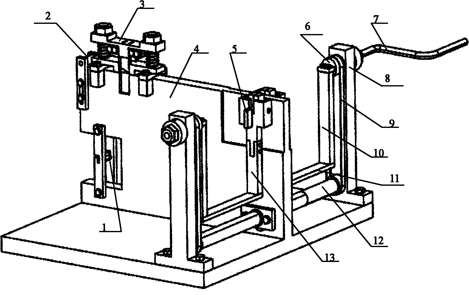
用于传送纸带的纸带装夹轴1和纸带压紧轮2装在立板4的后部,纸带裁剪成型刀具3装在纸带压紧轮2前方,所述的纸带裁剪成型刀具3有两套刀具,对称安装在立板4的两侧,纸带裁剪成型刀具3套在导向立柱16、22上,导向立柱固定在立板上,其上装有弹簧,纸带裁剪成型刀具3能沿导向立柱上下移动,由螺母18、19限位,靠弹簧复位,所述的纸带裁剪成型刀具3每套由左刀片25、主刀片26和右刀片27组成,左、右刀片25、27通过刀片压紧块24固定,两个主刀片26通过两个楔形块28夹紧固定,左、右刀片25、27与主刀片26成90°布置在主刀片26两侧见图5,每片刀片便于更换。The paper tape clamping shaft 1 and the paper
所述的纸带压紧块21用于压紧纸带,其两侧开有与刀具对应的导向槽。The paper
所述的夹紧装置5和转动传动部分安装在立板4的前端,夹紧装置5为2套,对称安装在立板4前端的两侧。每套夹紧装置5,包括固定座33,其内装有2个夹紧块30、32,分别通过弹簧压紧,其中间装有一带偏心结构的夹紧手柄31,通过旋转夹紧手柄31,能使2个夹紧块张开,其作用是将剪裁成型的T型纸带和粘纤夹于夹紧装置处。两个固定座33与第一、第二曲柄10、13分别通过键槽配合,用圆锥销固定。The clamping device 5 and the rotating transmission part are installed on the front end of the vertical plate 4, and the clamping device 5 is two sets, which are symmetrically installed on both sides of the front end of the vertical plate 4. Each set of clamping device 5 includes a fixed
所述的转动传动部分由分别设在立板4前端两侧的曲柄、连杆机构和齿形轮、齿形带组成。立板4右侧的第一曲柄10上端固定在齿形轮6上,齿形轮6固定在位于立柱8上的两个滚珠轴承15旋转轴14的一端,其旋转轴另一端与手柄7固定连接;第一曲柄10下端通过连杆机构11、曲柄与右边夹紧装置5的固定座33连接。立板4左侧的第二曲柄13与左侧的夹紧装置5之间具有相同的连接结构。两根立柱8固定在底座前端角上,两个立柱的下部装有同轴的传动轴12,其两端带有齿形轮。转动手柄7,带动同轴的齿形轮6转动,通过同步齿形带9传动,带动传动轴12上的齿形轮转动,由齿形带驱动左侧的齿形轮同步转动,因传动结构是1∶1的,因此保证两套夹紧装置5能够同步旋转。左右两套夹紧装置5的转动轴线为四个滚珠轴承15所确定的轴线。Described rotation transmission part is made up of the crank that is respectively arranged on the two sides of vertical plate 4 front ends, connecting rod mechanism and toothed wheel, toothed belt. The upper end of the
所述的粘纤切丝装置主要由切丝装置底座43、上、下夹丝机构46、51、切片器定位装置47、切片器夹紧装置48、旋转轴50和切片器组成,所述的上、下夹丝机构46、51分别布置在切片器定位装置47的上面和下面,切片器定位装置47通过旋转手柄45控制翻转。所述的切片器包括:切片器主体39和夹紧座42;切片器主体39上开有切片器槽,夹紧座42插入切片器槽中,通过夹紧座42上的顶片将切片器槽中包有遮光套的集束粘纤夹紧。切片器装在切片器定位装置47上,并通过设在夹紧座42一端的切片器夹紧装置48夹紧定位。The viscose fiber cutting device is mainly composed of a
所述的照明装置由半球形光源支座59和发光二极管60组成,发光二极管60分三层紧密排布,中心放置一个,层和层之间的发光二极管交错放置,固定在半球形光源支座59中。The lighting device is composed of a hemispherical
一种用于上述的集束粘纤计数和断面形态分析系统的图像快速处理方法,具体处理步骤:A fast image processing method for the above-mentioned bundled viscose fiber counting and section shape analysis system, specific processing steps:
步骤一,采用3×3平滑模板,对图像平滑四次,接着采用线性拉伸算法来对图像进行增强;Step 1, using a 3×3 smoothing template to smooth the image four times, and then using a linear stretching algorithm to enhance the image;
步骤二,系统采用基于梯度算子的自适应阈值分割方法,行和列分别进行处理,对图像进行背景清除:首先对源图像进行梯度计算,提取梯度极值,接着判断极值的正负,如果极值为正存入正数组,反之为负存入负数组,最后根据正负值进行行或列背景的消除,分割后采用全局低阈值分割,这样就获取了我们需要的分割图像;
步骤三,对分割后图像局部粘连部分进行分离,确保每根粘纤断面彼此分离,为计数提供方便;Step 3: Separating the local adhesion part of the image after segmentation to ensure that the sections of each sticky fiber are separated from each other to provide convenience for counting;
步骤四,断面图像计数时,首先对图像进行线段编码,然后依据区域特征参数判别单点连通区域并进行计数;Step 4, when counting cross-sectional images, the image is first encoded with line segments, and then the single-point connected regions are identified and counted according to the regional characteristic parameters;
步骤五,计数完毕后,对各粘纤断面进行形态学计算,对形态异常的粘纤进行判别并标记,这样就完成了粘纤数目检测及其形态的分析,并且系统具有数据存储和历史检测数据查询功能。Step 5: After the counting is completed, perform morphological calculations on each viscose fiber section, identify and mark the viscose fibers with abnormal shapes, thus completing the detection of the number of viscose fibers and the analysis of their morphology, and the system has data storage and historical detection Data query function.
该系统和方法可一次检测20--30锭单丝单丝由几十根细丝组成,种类大致有18根、30根、45根、60根几种,即每次检测粘纤数目约为360-1800根数目并做形态分析。The system and method can detect 20--30 ingots of monofilament at one time. 360-1800 root count and do morphological analysis.
本发明的有益效果是:多束单丝一次计数,实现快速测试的目的。通过对丝的断面面积的测试,可对粘纤形态进行分析,检验出喷丝板的堵孔状况。The beneficial effect of the invention is that multiple bundles of monofilaments can be counted at one time, and the purpose of rapid testing can be realized. By testing the cross-sectional area of the filament, the morphology of the viscose fiber can be analyzed, and the plugging of the spinneret can be checked.
附图说明Description of drawings
图1采用技术方案框图;Figure 1 adopts a technical scheme block diagram;
图2集束粘纤遮光套自动制作装置正视立体图;Figure 2 is a front perspective view of the automatic production device for bundled viscose fiber shading sleeves;
图3集束粘纤遮光套自动制作装置后视立体图;Fig. 3 rear perspective view of the automatic production device for bundled viscose shading cover;
图4图2A-A剖视图Fig. 4 Fig. 2A-A sectional view
图5纸带裁剪成型刀具安装局部立体图;Figure 5 is a partial three-dimensional view of the paper tape cutting and forming tool installation;
图6纸带压紧块结构立体图;Figure 6 is a three-dimensional view of the structure of the paper tape pressing block;
图7刀具结构立体图;Figure 7 is a three-dimensional view of the tool structure;
图8图7的仰视图;The bottom view of Fig. 8 Fig. 7;
图9夹紧装置安装局部立体图;Figure 9 is a partial perspective view of the installation of the clamping device;
图10夹紧装置局部结构B-B剖视图;Figure 10 B-B sectional view of the local structure of the clamping device;
图11带有偏心结构的夹紧手柄;Figure 11 clamping handle with eccentric structure;
图12夹紧时包裹有粘纤的纸带示意图;The schematic diagram of the paper tape wrapped with viscose fiber when Fig. 12 is clamped;
图13切片器结构图;Figure 13 Slicer structure diagram;
图14切片器夹紧座立体图;Fig. 14 perspective view of the clamping seat of the slicer;
图15切片器主体结构立体图;Figure 15 is a three-dimensional view of the main structure of the slicer;
图16集束粘纤切丝器结构图;Fig. 16 Structural diagram of bundle viscose cutter;
图17固定好切片器后集束粘纤切丝器结构图;Fig. 17 is a structural diagram of the bundled viscose fiber cutter after the slicer is fixed;
图18检测系统图;Figure 18 detection system diagram;
图19光源结构图;Figure 19 Light source structure diagram;
图20粘纤图像软件处理流程图。Fig. 20 Flow chart of viscose image software processing.
图21基于梯度算子的自适应阈值分割法流程图。Fig. 21 is a flowchart of the adaptive threshold segmentation method based on the gradient operator.
图中:1-纸带装夹轴 2-纸带压紧轮 3-纸带裁剪成型刀具 4-立板 5-夹紧装置6-齿形轮 7-手柄 8-立柱 9-同步齿形带 10-第一曲柄 11-连杆机构12-传动轴 13-第二曲柄 14-轴承旋转轴 15-滚珠轴承 16-导向立柱a17-弹簧a 18-螺母a 19-螺母b 20-弹簧b 21-纸带压紧块 22-导向立柱b23-导向槽 24-刀片压紧块 25-左刀片 26-主刀片 27-右刀片 28-楔形快29-弹簧c 30-夹紧块a 31-夹紧手柄 32-夹紧块b 33-固定座 34-弹簧d35-纸带左边部分 36-T形纸带 37-纸带右边部分 38-集束粘纤 39-切片器主体40-包裹遮光纸的集束粘纤 41-顶片 42-夹紧座 43-切丝装置底座 44-锁紧手柄45-旋转手柄 46-上夹丝机构 47-切片器定位装置 48-切片器夹紧装置 49-顶丝50-旋转轴 51-夹丝机构b 52-集束粘纤 53-照明装置 54-切片器 55-显微物镜56-CCD摄像头 57-二维平移工作台 58-计算机 59-半球形光源支座 60-发光二极管In the figure: 1-tape clamping shaft 2-tape pressure wheel 3-tape cutting tool 4-stand 5-clamping device 6-toothed wheel 7-handle 8-column 9-synchronous toothed belt 10-first crank 11-link mechanism 12-transmission shaft 13-second crank 14-bearing rotating shaft 15-ball bearing 16-guide column a17-spring a 18-nut a 19-nut b 20-spring b 21- Paper tape pressing block 22-guide column b23-guide groove 24-blade pressing block 25-left blade 26-main blade 27-right blade 28-wedge fast 29-spring c 30-clamping block a 31-clamping handle 32-Clamping block b 33-Fixer seat 34-Spring d35-Left part of paper tape 36-T-shaped paper tape 37-Right part of paper tape 38-Combined viscose fiber 39-Slicer main body 40-Combined viscose fiber wrapped with shading paper 41-top piece 42-clamping seat 43-cutting device base 44-locking handle 45-rotating handle 46-up clamping mechanism 47-slicer positioning device 48-slicing device clamping device 49-top wire 50-rotation Axis 51-Wire clamping mechanism b 52-Bundling viscose fiber 53-Illumination device 54-Slicer 55-Microscopic objective lens 56-CCD camera 57-Two-dimensional translation worktable 58-Computer 59-Hemispherical light source support 60-Light emitting diode
具体实施方式Detailed ways
下面结合附图所述实施例进一步说明本发明的具体内容及工作过程。The specific content and working process of the present invention will be further described below in conjunction with the embodiments described in the accompanying drawings.
本发明解决上述技术问题采用如下的技术方案:将20-30锭单丝粘纤集束在一起,并包上遮光套,此项工作由集束粘纤遮光套自动制作装置参阅图2完成。制作完遮光套后放入粘纤切丝装置参阅图17中制作粘纤切片,切片器参阅图13所示,将制作好的粘纤切片连同切片器一起放入显微成像系统中,显微成像系统主要由:光源、二维移动底座、显微成像镜头和CCD摄像头组成。由于粘纤切片中的每根粘纤不能正好都呈竖直状态,导致成像明暗不均匀,为此专门设计了半球形LED光源参阅图19。光源发出的光经过粘纤切片,经显微光学系统放大后,成像于CCD摄像头处。CCD摄像头将所获取的数字图像传送至计算机,并对其进行特定的数字图像处理,主要处理的流程见图20。首先采集图像,由于所采集的图像包含较大噪声,因此对获取的图像进行噪声消除。消除噪声的图像存在亮度较暗,对比不明显的问题,所以有必要对图像增强。而后对图像进行基于梯度算子的自适应阈值分割方法进行分割,为了消除分割后图像局部粘连现象对图像连结区域予以分离。最后对分离后的图像进行粘纤数目计数及其形态分析,给出判别结果。The present invention solves the above-mentioned technical problems by adopting the following technical scheme: bundle 20-30 ingots of monofilament viscose fibers together and wrap them with a shading cover. After making the shading cover, put it into the viscose fiber cutting device. Refer to Figure 17 to make viscose fiber slices. See Figure 13 for the slicer. Put the prepared viscose fiber slices together with the slicer into the microscopic imaging system. The imaging system is mainly composed of: light source, two-dimensional mobile base, microscopic imaging lens and CCD camera. Since each sticky fiber in the sticky fiber slice cannot be just in a vertical state, resulting in uneven imaging, a hemispherical LED light source is specially designed for this purpose, see Figure 19. The light emitted by the light source passes through the viscose fiber section, and after being amplified by the microscopic optical system, it is imaged at the CCD camera. The CCD camera transmits the acquired digital image to the computer, and performs specific digital image processing on it. The main processing flow is shown in Figure 20. Firstly, the image is collected, and since the collected image contains relatively large noise, noise removal is performed on the obtained image. The noise-removed image has the problem of dark brightness and inconspicuous contrast, so it is necessary to enhance the image. Then the image is segmented by the adaptive threshold segmentation method based on the gradient operator. In order to eliminate the local adhesion phenomenon of the image after segmentation, the image connection area is separated. Finally, count the number of viscose fibers and analyze their morphology on the separated image, and give the result of discrimination.
本发明主要由以下几个重要部分组成:集束粘纤遮光套自动制作装置参阅图2;粘纤切丝装置参阅图17;照明装置参阅图19;具有二维移动工作台的体视显微镜参阅图18;图像采集和图像处理子程序参阅图20和图21。下面就每一部分予以详细说明。The present invention is mainly composed of the following important parts: see Figure 2 for the automatic production device of the bundled viscose shading cover; see Figure 17 for the viscose fiber cutting device; see Figure 19 for the lighting device; see Figure 19 for the stereo microscope with a two-dimensional
1、集束粘纤遮光套自动制作装置参阅图2和图31. Refer to Figure 2 and Figure 3 for the automatic production device of bundled viscose fiber shading cover
集束粘纤外侧包上一层遮光套,可以使最外层的单丝成像清晰,提高检测精度。集束粘纤遮光套自动制作装置主要由:遮光纸的传送部分、遮光纸的剪裁成型部分参阅图5、夹紧部分参阅图9、转动传动部分组成。主要作用是将直径不超过1mm,并且很软的集束粘纤用一层黑纸紧紧的包裹起来。结构参阅图2和图3(图2为结构正视立体图,图3为结构后视立体图),下面详细介绍其主要结构和功能。A layer of light-shielding sleeve is wrapped on the outside of the bundled viscose fiber, which can make the outermost monofilament image clear and improve the detection accuracy. The automatic production device for the bundled viscose shading cover is mainly composed of: the transmission part of the shading paper, the cutting and forming part of the shading paper (see Figure 5), the clamping part (see Figure 9), and the rotation transmission part. The main function is to tightly wrap the soft bundled viscose fibers with a diameter of no more than 1mm with a layer of black paper. Refer to Fig. 2 and Fig. 3 for the structure (Fig. 2 is a front perspective view of the structure, and Fig. 3 is a rear perspective view of the structure), and its main structure and functions are introduced in detail below.
包裹粘纤用黑纸提前被裁剪成纸带,卷在一圆形套筒上。放置在纸带装夹轴1中,纸从纸带压紧轮2下面穿过,用其压住。为了增大压紧力,在纸带压紧轮2上装有毛面橡胶套以增大摩擦力,调节纸带压紧轮2的上下位置可以调节压紧力的大小。纸带经过纸带压紧轮2后从纸带裁剪成型刀具3下穿过,纸带裁剪成型刀具3处为纸带裁剪成型部分,两侧都安装了成型刀具,其能够上下移动,靠弹簧复位。其结构如图5所示。4为立板,16、22为导向立柱,固定在立板上,弹簧17、20分别套在导向立柱16、22的圆柱形导向杆上。纸带裁剪成型刀具3套在导向立柱16、22上。刀具具体结构如图7所示。图7中,左、右刀片25、27分别用刀片压紧块24固定,主刀片26用两块楔形块28夹紧固定。这样,这三个成900位置安装的刀片就形成了一侧的刀片,在立板的另一侧有着同样的刀具结构。21为纸带压纸块,其结构如图6所示,其上有定位的圆孔,分别套在两个导向立柱的圆柱形导向杆上。纸带压紧块21的中间凹槽为导向槽,两套刀具位于立板4两侧,当纸带通过纸带压紧轮2后从纸带压紧块21下穿过。按下纸带裁剪成型刀具3,纸带压紧块21将纸带压紧在立板4上,刀具顺着纸带压紧块21的导向槽将纸带切断。为了使得纸带能够完全切断,在立板4上相应的位置也加工有导向槽23,并且两侧均有。这样纸被剪切成T字形状,放开纸带裁剪成型刀具3后,由于弹簧作用,刀具又恢复原来的位置。将裁剪成型的纸带拉至夹紧装置5中,夹紧装置5的结构如图9所示。29为弹簧c,30、32为夹紧块,放置在固定座33中。夹紧块a30能够沿弹簧c29的方向移动,夹紧块b32也具有相同的结构,两个夹紧块中间装有一带偏心结构的夹紧手柄31,结构见图11,转动夹紧手柄31,能够使两夹紧块张开。在操作时首先旋转夹紧手柄31,夹紧装置5将打开。这样的夹紧手柄31和夹紧装置5在立柱4左右两侧各有相同的一套。由于纸带已被剪切为T字形状,将纸带和粘纤夹于夹紧装置5处,具体结构如图9所示。在图12中,36为已被剪切为T字形状的纸带,38为集束粘纤,将纸带T形部分的一端即纸带左边部分35连同粘纤被两夹紧块30、32夹住。同样纸带的另一端即纸带右边部分37被另一端夹紧块夹住。夹紧后转动手柄7,带动同轴的齿形轮6转动,齿形轮通过曲柄、连杆机构已经与压紧块的固定座33连成一体,通过同步齿形带9传动,带动传动轴12上的齿形轮转动,由齿形带驱动另一侧的齿形轮转动,因传动结构是1∶1的,因此保证两套夹紧装置5能够同步旋转。旋转一圈后,遮光纸将集束粘纤紧紧包裹,切断纸带,这样就完成了粘纤遮光套的制作。The black paper for wrapping viscose is cut into paper strips in advance and rolled on a circular sleeve. Placed in the paper tape clamping shaft 1, the paper passes under the paper
2、集束粘纤切丝器参阅图162. Refer to Figure 16 for bundled viscose fiber cutter
为了在CCD靶面上成出清晰的粘纤断面的图像,要求粘纤断面尽可能平整,因此,集束粘纤的切丝方式尤为重要,经过反复、大量的试验,研制出方便、快捷、符合要求的切丝装置参阅图16,以下简称切丝器。其作用是:将带有遮光套的集束粘纤放入切片器图13中,制作粘纤切片。In order to form a clear image of the viscose fiber section on the CCD target surface, the viscose fiber section is required to be as smooth as possible. Therefore, the method of cutting the bundled viscose fiber is particularly important. The required shredding device is referring to Fig. 16, hereinafter referred to as shredder. Its effect is: put the bundled viscose fiber that has shading cover into slicer Fig. 13, make viscose fiber slice.
切片器参阅图13主要由:切片器主体39和夹紧座42组成。制作粘纤切片时,首先取下夹紧座42,将一段带遮光套的集束粘纤置于切片器槽中。将夹紧座42插入切片器槽中,通过其上的顶片41将切片器槽中粘纤夹紧,其夹紧后切片器槽中情况如图13中放大部分所示,其中40为集束粘纤。切片器外部尺寸和切片器定位装置47正好相配合,使得切片器能够正好放入切片器定位装置47中,这样便于装夹、定位。同时,在显微镜二维工作台图18上也固定有类似于切片器定位装置47的装夹、定位装置,这样可以实现快速装夹、定位,避免每次检测时调节工作台位置。Referring to FIG. 13 , the slicer is mainly composed of: a slicer
集束粘纤切丝器图16主要由切丝装置底座43、上、下夹丝机构46、51、切片器定位装置47、切片器夹紧装置48、旋转轴50组成。功能是将带有遮光套的一段集束粘纤,连同切片器放到切片器定位装置47上,用上、下夹丝机构46、51将粘纤两端夹紧并张紧,锁紧44锁紧手柄,使得切片器定位装置47稳固,先用单面刀片,沿着切片器上表面切断集束粘纤,再将旋转手柄45旋转180°,切片器定位装置47连同其上的带有集束粘纤的切片器一同翻转,使另一侧张紧的粘纤朝上,锁紧44锁紧手柄,用同样方式平齐切断另一侧粘纤。制作有利于通光和成像的粘纤断面切片。将切片器放置于集束粘纤切丝器上并固定后的装置如图17所示,其中52为集束粘纤。The bundled viscose fiber cutter shown in FIG. 16 is mainly composed of a
3、照明装置参阅图193. Refer to Figure 19 for the lighting device
照明系统决定获取图像的清晰程度,因而直接影响系统检测精度。切片中的粘纤不可能都保持竖直,当用平行光源等照明时,使得光不可能均匀透过每一根粘纤,造成粘纤断面亮度不均匀;成像的不清晰。经过反复试验,设计了半球型光源参阅图19。发光二极管60分三层紧密排布,中心放置一个,层和层之间的发光二极管交错放置,固定在半球形光源支座59中。The illumination system determines the clarity of the acquired image, thus directly affecting the detection accuracy of the system. It is impossible for all the viscose fibers in the section to be kept vertical. When illuminated with a parallel light source, it is impossible for the light to pass through each viscose fiber uniformly, resulting in uneven brightness of the viscose fiber section; the image is not clear. After trial and error, a hemispherical light source was designed, see Figure 19. The light-emitting
4、具有二维移动工作台的体视显微镜参阅图184. Refer to Figure 18 for a stereo microscope with a two-dimensional mobile worktable
体视显微镜的工作台,具有二维平移机构57,可将制作好的带有粘纤切片的切片器54移动到显微镜的光轴处。二维平移导轨均采用滚珠直线导轨。体视显微镜具有9倍物镜放大倍率,且采用很好的消球差和畸变的、高分辨率的物镜。参阅图18中,53为照明装置参阅图19,55为显微成像物镜,56为CCD摄像头,58为数据处理用计算机。The workbench of the stereo microscope has a two-
5、图像采集和处理参阅图20、215. Image acquisition and processing refer to Figures 20 and 21
图像采集和处理:就是采用CCD图像传感器,获取粘纤切片断面图像,将获取的图像信息输送至计算机。计算机对其采集的图像信息进行处理,以获取粘纤数目和形态信息。Image acquisition and processing: the CCD image sensor is used to obtain the section image of the viscose fiber slice, and the acquired image information is sent to the computer. The computer processes the image information collected by it to obtain the number and shape information of viscose fibers.
粘纤集束断面计数和形态分析采用如下方法:The following methods are used for the counting and morphological analysis of viscose fiber bundles:
1采用3×3平滑模板,对图像平滑四次,接着采用线性拉伸算法来对图像进行增强。1 Using a 3×3 smoothing template, the image is smoothed four times, and then a linear stretching algorithm is used to enhance the image.
2系统采用一种基于梯度算子的自适应阈值分割方法。行和列分别进行处理,对图像进行背景清除。算法流程如图21所示,首先对源图像进行梯度计算,提取梯度极值。接着判断极值的正负,如果极值为正存入正数组,反之为负存入负数组。最后根据正负值进行行或列背景的消除,分割后采用全局低阈值分割,这样就获取了我们需要的分割图像。2 The system adopts an adaptive threshold segmentation method based on gradient operator. Rows and columns are processed separately to perform background removal on the image. The algorithm flow is shown in Figure 21. First, the gradient calculation is performed on the source image, and the gradient extremum is extracted. Then judge whether the extreme value is positive or negative. If the extreme value is positive, it will be stored in the positive array, otherwise it will be negative and stored in the negative array. Finally, the row or column background is eliminated according to the positive and negative values, and the global low-threshold segmentation is used after segmentation, so that the segmented image we need is obtained.
3对分割后图像局部粘连部分进行分离,确保每根粘纤断面彼此分离,为计数提供方便。3. Separating the local adhesive part of the image after segmentation to ensure that the sections of each adhesive fiber are separated from each other, which provides convenience for counting.
4断面图像计数时,首先对图像进行线段编码,然后依据区域特征参数判别单点连通区域并进行计数。When counting 4-section images, the image is first encoded with line segments, and then the single-point connected regions are identified and counted according to the region characteristic parameters.
5计数完毕后,对各粘纤断面进行形态学计算,对形态异常的粘纤进行判别并标记。这样就完成了粘纤数目检测及其形态的分析,并且系统具有数据存储和历史检测数据查询功能。5. After counting, carry out morphological calculation on each viscose fiber section, and distinguish and mark the viscose fiber with abnormal shape. In this way, the detection of the number of viscose fibers and the analysis of their morphology are completed, and the system has the functions of data storage and historical detection data query.
本发明的工作过程参阅图1:将20--30锭单丝粘纤集束,包上遮光套,用切丝装置将带有遮光套的集束粘纤上下两端平齐切断,将制作好的粘纤切片连同切片器一起,送入体视显微镜。照明装置发出的光透过粘纤切片后,经显微物镜放大成像至CCD摄像头,由CCD摄像头将图像数据传输至计算机进行处理。图像处理综合运用了图像消噪声,图像增强,图像分割,图像分离,粘纤计数,形态分析等数字图像处理算方法。测试结果给出粘纤的根数和断面形态,由此判断粘纤的质量和喷丝板的工作状态。Refer to Figure 1 for the working process of the present invention: bundle 20--30 spindles of monofilament viscose fiber, wrap it with a shading cover, and cut off the upper and lower ends of the bundled viscose fiber with the shading cover evenly with a shredding device, and the finished The viscose sections are fed into the stereomicroscope together with the microtome. The light emitted by the illuminating device passes through the viscose section, and is enlarged and imaged by the microscope objective lens to the CCD camera, and the CCD camera transmits the image data to the computer for processing. Image processing comprehensively uses digital image processing algorithms such as image denoising, image enhancement, image segmentation, image separation, viscose fiber counting, and morphological analysis. The test results give the number of viscose fibers and the cross-sectional shape, from which the quality of viscose fibers and the working state of the spinneret can be judged.
1.制作粘纤的遮光套1. Make viscose shading cover
将带状黑纸用纸带压紧轮2压紧,送入剪裁成型部位置,按下纸带裁剪成型刀具3,将纸剪裁成T字型,打开夹紧手柄31,将集束粘纤和纸带一起放入夹紧装置5中。转动手柄7一圈,遮光纸将集束粘纤紧紧包裹,用刀将纸断开。即完成了粘纤遮光套的制作。Compress the strip-shaped black paper with the paper
2.切丝2. Shredded
将一段约200mm长,中间带有遮光套的集束粘纤送入粘纤切片器里夹紧参阅图17,将粘纤上下两端用夹丝机构46、51夹住,使粘纤处于张紧状态。转动旋转手柄45,使得切片器待检面处于上面,旋紧锁紧手柄44,使切片器定位装置47稳固,用单面刀片沿着切片器上表面平齐切断粘纤。再将旋转手柄45旋转180°,切片器定位装置47和其上带有集束粘纤的切片器一同翻转,使另一侧张紧的粘纤朝上,锁紧44锁紧手柄,用同样方式平齐切断另一侧粘纤,完成粘纤切片的制作。Send a section of about 200mm long bundled viscose fiber with a shading sleeve in the viscose fiber slicer for clamping. Refer to Figure 17, clamp the upper and lower ends of the viscose fiber with clamping
3.成像3. Imaging
将夹有带遮光套的集束粘纤的切片器送入体视显微镜参阅图18工作台定位座处,移动二维工作台57,将粘纤断面切片移到显微镜的光轴处,调焦,将粘纤清晰成像至CCD摄像头56上。Send the slicer with the bundled viscose fiber with the light-shielding cover into the stereomicroscope referring to the positioning seat of the workbench in Figure 18, move the two-
4.图像获取与处理4. Image acquisition and processing
通过CCD获取集束粘纤断面图像信息。利用本发明提供的方法对图像消噪声,图像增强,图像分割,图像分离,对分离的图像进行线段编码,然后依据区域特征参数判别单点连通区域并进行计数。对各粘纤断面进行形态学计算,对形态异常的粘纤进行判别并标记。这样就完成了粘纤数目检测及其形态的分析。The cross-sectional image information of bundled viscose fibers is obtained by CCD. Using the method provided by the invention to eliminate noise, image enhancement, image segmentation, image separation, line segment coding for the separated image, and then distinguish and count the single-point connected areas according to the area feature parameters. Carry out morphological calculation on each viscose fiber section, and distinguish and mark the viscose fiber with abnormal shape. In this way, the detection of the number of viscose fibers and the analysis of their morphology are completed.
Claims (8)
Priority Applications (1)
| Application Number | Priority Date | Filing Date | Title |
|---|---|---|---|
| CN201010575699A CN102094314B (en) | 2010-12-07 | 2010-12-07 | Cluster sticky fiber counting and cross section form analyzing system and rapid image processing method |
Applications Claiming Priority (1)
| Application Number | Priority Date | Filing Date | Title |
|---|---|---|---|
| CN201010575699A CN102094314B (en) | 2010-12-07 | 2010-12-07 | Cluster sticky fiber counting and cross section form analyzing system and rapid image processing method |
Publications (2)
| Publication Number | Publication Date |
|---|---|
| CN102094314A true CN102094314A (en) | 2011-06-15 |
| CN102094314B CN102094314B (en) | 2011-12-21 |
Family
ID=44127569
Family Applications (1)
| Application Number | Title | Priority Date | Filing Date |
|---|---|---|---|
| CN201010575699A Expired - Fee Related CN102094314B (en) | 2010-12-07 | 2010-12-07 | Cluster sticky fiber counting and cross section form analyzing system and rapid image processing method |
Country Status (1)
| Country | Link |
|---|---|
| CN (1) | CN102094314B (en) |
Cited By (1)
| Publication number | Priority date | Publication date | Assignee | Title |
|---|---|---|---|---|
| CN109859175A (en) * | 2019-01-09 | 2019-06-07 | 广州大学 | A kind of image processing method and device counted for triode |
Citations (5)
| Publication number | Priority date | Publication date | Assignee | Title |
|---|---|---|---|---|
| US5231580A (en) * | 1991-04-01 | 1993-07-27 | The United States Of America As Represented By The Secretary Of The Department Of Health And Human Services | Automated method and apparatus for determining characteristics of nerve fibers |
| US5294973A (en) * | 1992-11-27 | 1994-03-15 | Bridgestone/Firestone, Inc. | Method and apparatus for determining body ply cord distribution |
| DE19648272A1 (en) * | 1996-11-21 | 1998-05-28 | Emitec Emissionstechnologie | Method and device for determining a cell density of a honeycomb body, in particular for an exhaust gas catalytic converter |
| CN1865845A (en) * | 2006-06-22 | 2006-11-22 | 上海交通大学 | Method for making calibrating plate on flat display screen |
| CN101177912A (en) * | 2007-11-29 | 2008-05-14 | 吉林大学 | Viscose filament number and single filament diameter detector |
-
2010
- 2010-12-07 CN CN201010575699A patent/CN102094314B/en not_active Expired - Fee Related
Patent Citations (5)
| Publication number | Priority date | Publication date | Assignee | Title |
|---|---|---|---|---|
| US5231580A (en) * | 1991-04-01 | 1993-07-27 | The United States Of America As Represented By The Secretary Of The Department Of Health And Human Services | Automated method and apparatus for determining characteristics of nerve fibers |
| US5294973A (en) * | 1992-11-27 | 1994-03-15 | Bridgestone/Firestone, Inc. | Method and apparatus for determining body ply cord distribution |
| DE19648272A1 (en) * | 1996-11-21 | 1998-05-28 | Emitec Emissionstechnologie | Method and device for determining a cell density of a honeycomb body, in particular for an exhaust gas catalytic converter |
| CN1865845A (en) * | 2006-06-22 | 2006-11-22 | 上海交通大学 | Method for making calibrating plate on flat display screen |
| CN101177912A (en) * | 2007-11-29 | 2008-05-14 | 吉林大学 | Viscose filament number and single filament diameter detector |
Non-Patent Citations (2)
| Title |
|---|
| 《中国优秀硕士学位论文全文数据库 信息科技辑》 20091015 付威威 粘胶长丝端面计数系统的结构设计与算法研究 第21-55页 8 , 第10期 2 * |
| 《吉林大学学报(理学版)》 20100930 张佳全,等 喷丝板单孔图像的检测算法 第835-839页 1-8 第48卷, 第5期 2 * |
Cited By (1)
| Publication number | Priority date | Publication date | Assignee | Title |
|---|---|---|---|---|
| CN109859175A (en) * | 2019-01-09 | 2019-06-07 | 广州大学 | A kind of image processing method and device counted for triode |
Also Published As
| Publication number | Publication date |
|---|---|
| CN102094314B (en) | 2011-12-21 |
Similar Documents
| Publication | Publication Date | Title |
|---|---|---|
| JP7713462B2 (en) | Sectioning and quality control in microtomy | |
| CN102253052B (en) | Grain quality on-line detection apparatus based on field programmable gate array (FPGA) | |
| CN109035244B (en) | Automatic cocoon picking system, automatic cocoon picking machine and cocoon picking method | |
| CN1043791C (en) | Needle-based apparatus for individualizing fibers and other textile entities for testing purposes | |
| TW201743047A (en) | Methods and apparatus for edge surface inspection of a moving glass web | |
| JPH06220771A (en) | Method for detecting artificial fiber or flaw fiber or other foreign substance in treating silk waste and related apparatus | |
| CN214555423U (en) | Accurate bearing is sieving mechanism for steel ball | |
| CN117043575A (en) | Preliminary diagnosis of cut tissue sections | |
| CN102094314B (en) | Cluster sticky fiber counting and cross section form analyzing system and rapid image processing method | |
| CN1290344A (en) | High volume fiber testing system | |
| CN118060193A (en) | Intelligent waste textile sorting system and method | |
| CN107621468A (en) | A kind of quality of roll for cotton rapid classification system | |
| CN119492613A (en) | A gauze tensile testing device for spinning processing | |
| CN113607661A (en) | Method for identifying leather product material based on hyperspectral imaging technology | |
| CN206715342U (en) | A kind of full-automatic banana stem fiber extractor | |
| CN115132603B (en) | Semiconductor chip detection device | |
| CN106680294A (en) | Device for detecting bright band of external circular surface of piston ring | |
| CN213364260U (en) | Cotton short fiber measuring device | |
| CN120594250A (en) | Intelligent detection system and method for cotton fiber breaking strength | |
| CN220231501U (en) | Fiber qualitative and quantitative detection device based on hyperspectral imaging technology | |
| CN112663311A (en) | Production of super soft cashmere sense cotton yarn is with cutting cotton yarn machine | |
| CN115564706B (en) | Method and device for automatic identification of rock composition | |
| CN112186450B (en) | Production system and process for mounting power line and plug | |
| CN105297148A (en) | Jute processing system | |
| CN114770629A (en) | Intelligent automatic whole kelp cutting and feeding system based on machine vision |
Legal Events
| Date | Code | Title | Description |
|---|---|---|---|
| C06 | Publication | ||
| PB01 | Publication | ||
| C10 | Entry into substantive examination | ||
| SE01 | Entry into force of request for substantive examination | ||
| C14 | Grant of patent or utility model | ||
| GR01 | Patent grant | ||
| C17 | Cessation of patent right | ||
| CF01 | Termination of patent right due to non-payment of annual fee |
Granted publication date: 20111221 Termination date: 20131207 |