CN102089938B - Two-pin connector and lamp using the same - Google Patents
Two-pin connector and lamp using the same Download PDFInfo
- Publication number
- CN102089938B CN102089938B CN2009801272373A CN200980127237A CN102089938B CN 102089938 B CN102089938 B CN 102089938B CN 2009801272373 A CN2009801272373 A CN 2009801272373A CN 200980127237 A CN200980127237 A CN 200980127237A CN 102089938 B CN102089938 B CN 102089938B
- Authority
- CN
- China
- Prior art keywords
- pin
- housing
- pin connector
- pair
- rotation
- Prior art date
- Legal status (The legal status is an assumption and is not a legal conclusion. Google has not performed a legal analysis and makes no representation as to the accuracy of the status listed.)
- Expired - Fee Related
Links
Images


Classifications
-
- F—MECHANICAL ENGINEERING; LIGHTING; HEATING; WEAPONS; BLASTING
- F21—LIGHTING
- F21V—FUNCTIONAL FEATURES OR DETAILS OF LIGHTING DEVICES OR SYSTEMS THEREOF; STRUCTURAL COMBINATIONS OF LIGHTING DEVICES WITH OTHER ARTICLES, NOT OTHERWISE PROVIDED FOR
- F21V21/00—Supporting, suspending, or attaching arrangements for lighting devices; Hand grips
- F21V21/14—Adjustable mountings
- F21V21/30—Pivoted housings or frames
-
- F—MECHANICAL ENGINEERING; LIGHTING; HEATING; WEAPONS; BLASTING
- F21—LIGHTING
- F21V—FUNCTIONAL FEATURES OR DETAILS OF LIGHTING DEVICES OR SYSTEMS THEREOF; STRUCTURAL COMBINATIONS OF LIGHTING DEVICES WITH OTHER ARTICLES, NOT OTHERWISE PROVIDED FOR
- F21V21/00—Supporting, suspending, or attaching arrangements for lighting devices; Hand grips
- F21V21/002—Supporting, suspending, or attaching arrangements for lighting devices; Hand grips making direct electrical contact, e.g. by piercing
-
- H—ELECTRICITY
- H01—ELECTRIC ELEMENTS
- H01R—ELECTRICALLY-CONDUCTIVE CONNECTIONS; STRUCTURAL ASSOCIATIONS OF A PLURALITY OF MUTUALLY-INSULATED ELECTRICAL CONNECTING ELEMENTS; COUPLING DEVICES; CURRENT COLLECTORS
- H01R33/00—Coupling devices specially adapted for supporting apparatus and having one part acting as a holder providing support and electrical connection via a counterpart which is structurally associated with the apparatus, e.g. lamp holders; Separate parts thereof
- H01R33/05—Two-pole devices
- H01R33/06—Two-pole devices with two current-carrying pins, blades or analogous contacts, having their axes parallel to each other
- H01R33/08—Two-pole devices with two current-carrying pins, blades or analogous contacts, having their axes parallel to each other for supporting tubular fluorescent lamp
- H01R33/0836—Two-pole devices with two current-carrying pins, blades or analogous contacts, having their axes parallel to each other for supporting tubular fluorescent lamp characterised by the lamp holding means
- H01R33/0854—Two-pole devices with two current-carrying pins, blades or analogous contacts, having their axes parallel to each other for supporting tubular fluorescent lamp characterised by the lamp holding means with lamp rotating means
-
- F—MECHANICAL ENGINEERING; LIGHTING; HEATING; WEAPONS; BLASTING
- F21—LIGHTING
- F21K—NON-ELECTRIC LIGHT SOURCES USING LUMINESCENCE; LIGHT SOURCES USING ELECTROCHEMILUMINESCENCE; LIGHT SOURCES USING CHARGES OF COMBUSTIBLE MATERIAL; LIGHT SOURCES USING SEMICONDUCTOR DEVICES AS LIGHT-GENERATING ELEMENTS; LIGHT SOURCES NOT OTHERWISE PROVIDED FOR
- F21K9/00—Light sources using semiconductor devices as light-generating elements, e.g. using light-emitting diodes [LED] or lasers
- F21K9/20—Light sources comprising attachment means
- F21K9/27—Retrofit light sources for lighting devices with two fittings for each light source, e.g. for substitution of fluorescent tubes
-
- F—MECHANICAL ENGINEERING; LIGHTING; HEATING; WEAPONS; BLASTING
- F21—LIGHTING
- F21Y—INDEXING SCHEME ASSOCIATED WITH SUBCLASSES F21K, F21L, F21S and F21V, RELATING TO THE FORM OR THE KIND OF THE LIGHT SOURCES OR OF THE COLOUR OF THE LIGHT EMITTED
- F21Y2115/00—Light-generating elements of semiconductor light sources
- F21Y2115/10—Light-emitting diodes [LED]
Landscapes
- Engineering & Computer Science (AREA)
- General Engineering & Computer Science (AREA)
- Non-Portable Lighting Devices Or Systems Thereof (AREA)
- Arrangement Of Elements, Cooling, Sealing, Or The Like Of Lighting Devices (AREA)
- Fastening Of Light Sources Or Lamp Holders (AREA)
Abstract
Description
背景技术 Background technique
荧光灯典型地包括每一端都被端罩罩住的玻璃灯管。引脚从端罩延伸以提供本技术领域所公知的双引脚连接器(bi-pin connector)。为了安装这些荧光灯,将引脚插入到公知为碑状件(tombstone)的电连接器内。然后旋转灯管以提供荧光灯管和碑状件之间的电连接和机械连接。Fluorescent lamps typically include glass tubes capped at each end by end caps. Pins extend from the endshield to provide what is known in the art as a bi-pin connector. To mount these fluorescent lamps, the pins are inserted into electrical connectors known as tombstones. The tube is then rotated to provide electrical and mechanical connections between the fluorescent tube and the tombstone.
采用发光二极管(LED)的灯用来替代荧光灯。当与绕灯管的纵向轴线360度发光的荧光灯管相比时,LED能够被看作是定向的点光源。已知的用来替代或更新荧光灯的LED灯采用环绕LED的半透明管状护套。该管状护套类似于荧光灯的玻璃灯管。双引脚连接器快速地连接至护套以罩住护套的每一端。Lamps employing light-emitting diodes (LEDs) are used to replace fluorescent lamps. When compared to a fluorescent tube that emits light 360 degrees around the longitudinal axis of the tube, an LED can be considered a directional point light source. Known LED lamps used to replace or retrofit fluorescent lamps employ a translucent tubular sheath surrounding the LED. The tubular jacket is similar to the glass tube of a fluorescent lamp. Two-pin connectors are quickly connected to the housing to cover each end of the housing.
为了将此LED灯连接至传统的荧光灯具,将双引脚连接器插入到相应的碑状件中并且旋转管状护套,这导致双引脚连接器的旋转。管状护套的旋转导致LED的旋转。这会引发问题,因为,如上面所提到的,当与荧光灯管相比时LED能够被看作是定向的点光源。当用来替代荧光灯的LED灯不是圆柱形的或者碑状件位于过紧的位置时,需要旋转管状护套或非圆柱形的壳体是令人讨厌的。另外,已知的双引脚连接器不能提供对灯的进一步调整。In order to connect this LED lamp to a conventional fluorescent light fixture, the bi-pin connector is inserted into the corresponding tombstone and the tubular sheath is rotated, which causes rotation of the bi-pin connector. Rotation of the tubular sheath causes rotation of the LED. This causes problems because, as mentioned above, LEDs can be seen as directional point sources of light when compared to fluorescent tubes. The need to rotate the tubular sheath or non-cylindrical housing is annoying when LED lamps intended to replace fluorescent lamps are not cylindrical or the tombstone is located in an overly tight position. Additionally, known two-pin connectors do not provide for further adjustment of the lamp.
发明内容 Contents of the invention
一种照明器具(lighting fixture),其能够与典型地用于荧光灯管的碑状件连接,包括:器具壳体;光源,布置在壳体中;以及双引脚连接器,附设至壳体并电连接至光源。该双引脚连接器包括引脚,这些引脚相对于壳体围绕介于引脚之间的旋转轴线旋转。A lighting fixture capable of being connected to a tombstone, typically for a fluorescent tube, comprising: a fixture housing; a light source disposed in the housing; and a two-pin connector attached to the housing and electrically connected to the light source. The two-pin connector includes pins that rotate relative to the housing about an axis of rotation between the pins.
本照明器具可包括偏压元件,以在平行于旋转轴线的方向上远离器具壳体抵推引脚。引脚还可相对于壳体在横切于旋转轴线的方向上移动。另外,本照明器具可进一步包括附设至壳体的附加双引脚连接器,该附加双引脚连接器包括相对于壳体旋转的引脚。此附加双引脚连接器不必电连接至光源。而是,此双引脚连接器可仅提供灯具(light fixture)与传统的碑状件的机械连接。The lighting fixture may include a biasing element to urge the pin away from the fixture housing in a direction parallel to the axis of rotation. The pin is also movable relative to the housing in a direction transverse to the axis of rotation. Additionally, the lighting fixture may further include an additional two-pin connector attached to the housing, the additional two-pin connector including pins that rotate relative to the housing. This additional two-pin connector does not have to be electrically connected to the light source. Instead, this bi-pin connector may only provide a mechanical connection of a light fixture to a traditional monument.
一种用于照明器(luminaire)的双引脚连接器,在照明器的方向性方面提供了更大的灵活性,本双引脚连接器包括:底座,构造成用于附设至相关的照明器壳体;以及引脚,相对于底座围绕与每一个引脚隔开的旋转轴线旋转。该双引脚连接器可包括连接器本体,该连接器本体包括用于与工具接合的台面(flat)或槽,以便于相对于底座旋转双引脚连接器本体。A two-pin connector for a luminaire providing greater flexibility in the orientation of the luminaire, the two-pin connector comprising: a base configured for attachment to an associated luminaire and the pins rotate relative to the base about an axis of rotation spaced from each pin. The bi-pin connector may include a connector body including a flat or slot for engagement with a tool to facilitate rotation of the bi-pin connector body relative to the base.
根据一个可替代的实施方式,一种照明器可包括:照明器壳体;光源,布置在壳体中;第一双引脚连接器,附设至壳体并电连接至光源;以及第二双引脚连接器,附设至壳体并与光源电绝缘。每一个双引脚连接器都可包括引脚,这些引脚相对于壳体围绕介于引脚之间的旋转轴线旋转。每一个双引脚连接器还可包括相对于壳体平移的引脚。According to an alternative embodiment, a luminaire may include: a luminaire housing; a light source disposed in the housing; a first bi-pin connector attached to the housing and electrically connected to the light source; and a second bi-pin connector A pin connector is attached to the housing and is electrically insulated from the light source. Each two-pin connector may include pins that rotate relative to the housing about an axis of rotation between the pins. Each two-pin connector may also include pins that translate relative to the housing.
在另一可替代的实施方式中,一种灯具可包括:器具壳体;光源,布置在器具壳体中;以及双引脚连接器,附设至壳体并电连接至光源。本双引脚连接器可包括在平行于轴线的第一方向上延伸的引脚,并且这些引脚能够相对于壳体在垂直于该轴线的方向上平移。In another alternative embodiment, a light fixture may include: a fixture housing; a light source disposed in the fixture housing; and a bi-pin connector attached to the housing and electrically connected to the light source. The present two-pin connector may include pins extending in a first direction parallel to the axis, and the pins are translatable relative to the housing in a direction perpendicular to the axis.
附图说明 Description of drawings
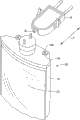
图1是连接至灯具壳体(仅示出了器具壳体的一部分)的双引脚连接器的透视图。Figure 1 is a perspective view of a two-pin connector connected to a light fixture housing (only a portion of the fixture housing is shown).
图2是从图1所示的对面看到的附设至灯具壳体的双引脚连接器的另一透视图。Figure 2 is another perspective view of the bi-pin connector attached to the light fixture housing, seen from the opposite side shown in Figure 1 .
图3是另一透视图,示出了包括双引脚连接器和与该双引脚连接器机械连接的传统碑状件的灯具。3 is another perspective view showing a light fixture including a bi-pin connector and a conventional monument mechanically connected to the bi-pin connector.
图4是图1中所示的双引脚连接器的分解图。FIG. 4 is an exploded view of the two-pin connector shown in FIG. 1 .
图5和图6是双引脚连接器的下透视图。图5示出了处于解锁构造中的双引脚连接器。图6示出了处于锁定构造中的双引脚连接器。5 and 6 are bottom perspective views of the two-pin connector. Figure 5 shows the two-pin connector in an unlocked configuration. Figure 6 shows the two-pin connector in a locked configuration.
图7是特写透视图,示出了灯具壳体和双引脚连接器之间的连接。Figure 7 is a close-up perspective view showing the connection between the light fixture housing and the bi-pin connector.
具体实施方式 Detailed ways
参照图1和图2,双引脚连接器10总体上包括附设至底座14的双引脚连接器本体12。连接器本体12和底座14均被示出为连接至端罩16,该端罩包括灯具壳体或照明器20(也被称为灯具)的照明器壳体18(图3)的一部分。参照图3,光源22布置在器具壳体18中。在图3中所描绘的实施方式中,光源是位于器具壳体18内的多个LED 22,每一个LED均面向同一方向。由于与围绕灯管的纵向轴线360度发光的荧光管灯相比,LED能够被看作是朝着一个大体方向发光的离散点光源,所以通常希望将LED定位在期望方向上,以使由照明器发出的光指向目标平面。例如,LED灯具已用来照亮商业冷藏展示柜的内容物。将要被照亮的目标平面在这种情况下是与冷藏展示柜的架子的前缘相交的竖直平面。目标平面还可以是建筑物的地板或者当将灯具用于向下照明场合时的地面。在这些情况下,期望来自LED 22的光指向目标平面,同时保持灯具壳体18相对于另一结构(例如商业冷藏展示柜的竖框或者向下照明场合中的建筑物的天花板)的特定方向。照明器20能够包括光学器件、反射镜、透镜和其它部件,以使光指向期望位置。Referring to FIGS. 1 and 2 , the
回来参照图1和图2,双引脚连接器10附设至器具壳体并且电连接至光源,该光源可以是图3中所示的LED 22或者另一类型的光源,例如荧光灯光源、白炽灯光源、弧形灯、激光二极管等。双引脚连接器10包括引脚24,这些引脚相对于端罩16(并且因此相对于图3中的器具壳体18)围绕介于引脚之间的旋转轴线26旋转。Referring back to FIGS. 1 and 2, the two-
参照图4,所描绘的实施方式中示出的双引脚连接器本体12包括罩(cap)30和轴环(collar)32。双引脚罩30包括圆形上端壁34。圆形上端壁34的中心与引脚24旋转所围绕的旋转轴线26同轴。罩30由不导电材料制成,优选地由塑料制成,以使引脚24彼此电绝缘。在图4所示的实施方式中,圆柱形外壁36从圆形上端壁34下垂。如果期望,圆柱形外壁36可包括台面以使扳手能够与外壁接合,或者包括槽以接收螺丝刀,从而便于相对于底座14旋转双引脚罩30,并且因此旋转双引脚连接器本体12。因此,罩30可具有其它构造,例如,在垂直于旋转轴线26截取的横截面上为多边形。Referring to FIG. 4 , the two-
圆柱形带键(keyed)杆38从圆形上端壁34下垂并且与旋转轴线26同轴。圆柱形带键杆38与圆柱形外壁36径向地隔开。圆柱形带键杆38下垂到圆柱形外壁36的下缘下方。如在图5和图6中更清楚地见到的,轴向对齐的凹口42形成在圆柱形带键杆38中。此凹口与轴环32以下面将更详细地描述的方式配合,以提供罩30和轴环32之间的带键连接。卡环44连接至圆柱形带键杆38,以将双引脚罩30附设至轴环32,从而限制罩30相对于轴环32沿旋转轴线26的平移运动。A cylindrical
如上面所提及的,连接器本体12还包括轴环32。轴环包括中央外圆柱形壁50,该中央外圆柱形壁的尺寸形成为接收在双引脚罩30的圆柱形外壁36和圆柱形带键杆38之间。轴环32也由不导电材料制成,例如由塑料制成。中央外圆柱形壁50在上端终止于环形台肩52。上外圆柱形壁54从台肩52朝着双引脚罩30向上延伸。圆柱形凸起(boss)56设置在上外圆柱形壁54内并与之同轴。凸起56包括完全贯穿轴环50的开口58。轴向对齐的键62从凸起56延伸到开口58中。键62与形成在双引脚连接器30的圆柱形带键杆38内的凹口42(图5)配合,以稳定双引脚连接器相对于轴环32的旋转运动。换言之,由于接收在凹口42中的键62,双引脚连接器30随轴环32一起旋转。As mentioned above, the
轴环32还包括从中央外圆柱形壁50下垂并且通向下圆柱形部分66的下锥形部分64。径向耳状件(ear)68从下圆柱形部分66的外围表面径向向外地延伸。轴环32可具有其它构造,尤其是当罩30具有可替换的构造时。
偏压元件(其在所描绘的实施方式中是弹簧72)远离器具壳体18(图3)偏压引脚24。在所描绘的实施方式中,弹簧72位于台肩52上并且环绕上外圆柱形壁54,以远离轴环32偏压双引脚罩30。弹簧72接收在双引脚罩30的圆柱形外壁36和圆柱形带键杆38之间。圆柱形带键杆38通过孔58接收在轴环32内,并且卡环44保持双引脚罩30,以限制双引脚罩相对于轴环32以及相对于底座14并且因此相对于端罩16以及器具壳体18(图3)的移动。弹簧72能够吸收任何可由于照明器具在为碑状件安装托架时的变形所导致的松弛,包括双引脚连接器10的新的照明器具将安装在该碑状件中。例如,在已经由荧光灯管照亮的冷藏展示柜中,包括双引脚连接器10的LED灯组件典型地比它将替代的荧光灯管重。附设有碑状件的托架的额外重量可能导致托架弯曲。弹簧72朝着碑状件(或者仅是其中一个碑状件)抵推引脚24,以吸收由于托架变形所导致的松弛。A biasing element, which in the depicted embodiment is a
而且,在器具的每一端都包括一个双引脚连接器的灯具可以仅是双引脚连接器中的一个电连接至器具内的光源,而留下另一个双引脚连接器与光源电绝缘。典型地,电绝缘的双引脚连接器将包括弹簧,而与光源电连通的另一连接器将典型地不包括弹簧。Also, a luminaire that includes a two-pin connector at each end of the fixture may have only one of the two-pin connectors electrically connected to the light source within the fixture, leaving the other two-pin connector electrically isolated from the light source . Typically, the electrically insulating two-pin connector will include a spring, while the other connector in electrical communication with the light source will typically not include a spring.
参照图4,双引脚连接器本体12其在所描绘的实施方式中包括双引脚罩30和轴环32,但可制成一个件或者一个单元,该双引脚连接器本体连接至底座14并且相对于底座是可旋转的。底座14包括与旋转轴线26同轴的圆形开口80并包括彼此偏移180度的带键部分82。开口80接收轴环32的下圆柱形部分66,并且带键部分82接收径向耳状件68。旋转本体12以连接至底座14。Referring to Figure 4, a
底座14包括位于底座14的相对侧上的延伸件84。每一个延伸件84都横切于旋转轴线26而延伸。每一个延伸件84都包括引导斜面86和从该斜面向后设置的多个棘爪88。延伸件84,并且尤其是棘爪88,与弹簧卡夹(clip)92和端罩16以下面将更详细地描述的方式配合。如上面所提及的,旋转本体12以连接至底座14。The
如在图5和图6中更清晰看到的,斜面94形成在底座14的邻近开口80的带键部分82的下表面上。小凸块96与沿开口80的周向移动的每个斜面94隔开。斜面94的后缘与凸块96的邻近边缘之间的距离使得耳状件64接收在斜面94和凸块96之间,以将引脚24(图1和2)锁定在解锁位置中,这在图1和5中示出。止动件98与每一个斜面94的后缘隔开大致90度。小凸块102,类似于小凸块96,位于每一个止动件98之前。小凸块102与止动件98隔开,以将耳状件64接收在锁定位置中(参见图2和6)。As seen more clearly in FIGS. 5 and 6 , a
端罩16典型地附设至器具壳体18。因此,端罩也可被看作是器具壳体的一部分。回来参照图4,端罩16包括用于将底座14连接至端罩16的连接结构110。每一个连接结构110都包括凹口112,每一个凹口都构造成接收相应的弹簧卡夹92和底座14的相应延伸件84。底座14和端罩16之间的连接允许相对于端罩16(以及器具壳体18)在横切于双引脚连接器10的旋转轴线26的轴线T上对底座进行调整。参照图7,形成在对应的安装结构110中的每一个横向槽112包括台阶114。通过使弹簧卡夹92和延伸件84接收在相应的横向槽112中,台阶114限制双引脚连接器10相对于端罩16的向后平移运动。弹簧卡夹92插入到横向槽112中并且包括与形成在底座14的每一个延伸件84中的棘爪88(图4)配合的弯曲突起116。突起116接收在相应的棘爪88中,以控制底座14相对于端罩16在横切于旋转轴线26且更特别地与该旋转轴线垂直的轴线T上的平移运动。底座14和端罩16之间的这类连接允许引脚24的平移运动。这有利于例如相对于可在商业冷藏展示柜中可看到的碑状件t(图3)适当地定位器具壳体18。例如,当器具壳体18紧邻冷藏展示柜的竖框,但双引脚连接器与碑状件t沿轴线T没有适当地对齐时,则双引脚连接器能够在此轴线上平移,因此这些双引脚连接器能够插入到碑状件t中。The
再次参照图4,端罩16还包括穿过端罩16在安装结构110之间形成的开口120。电线122(在图5中示意性地描绘)穿过开口120延伸,以提供引脚24和光源22(图3)之间的电连接。端罩16还包括接收用于将端罩16附设至器具壳体18的紧固件126(图3)的紧固件开口124。密封垫或者垫圈可介于端罩16的外表面和底座14的下表面之间,以防止水分进入照明器具的壳体18。可替代地,橡胶状的插塞(plug)可插入到开口120中,并且电线可穿过插塞中的小开口延伸。Referring again to FIG. 4 , the
图1描绘了处于解锁构造中的双引脚连接器10。包括双引脚连接器10的灯具或者照明器20附设至传统的碑状件,例如图3中所示的碑状件。引脚24插入到处于解锁构造中(图1)的碑状件的槽中,并且一旦插入,在碑状件t中旋转预定的距离至图2中所示出的锁定构造。在双引脚连接器10包括连接至引脚24的电线122(图5)的情况下,当连接器插入碑状件并且在碑状件t中旋转时,形成电连接和机械连接两者。如果需要,照明器20在双引脚连接器的一个中不必包括电线122(另一个双引脚连接器将附设在照明器20的相对端)。光源(例如图3中所示出的LED 22)能够构造成仅通过双引脚连接器中的一个接收电力,而另一个双引脚连接器能够与光源电绝缘。不具有电线的双引脚连接器仍会以与包括电线的双引脚连接器相同的方式来机械地操作,但仅在双引脚连接器与用于不具有电线的双引脚连接器的碑状件t之间会形成机械连接。不具有电线的双引脚连接器最可能会包括弹簧72,而包括电线的双引脚连接器可以不包括弹簧。当LED用作光源时,由于LED是定向的,因此变得更期望将LED定向在特定的方向上。此处所描述的双引脚连接器允许这样。Figure 1 depicts the two-
已参照特定实施方式描述了双引脚连接器。阅读并理解了以上描述的那些人能够进行修改和替换。本发明不限于此处所公开的那些实施方式。而是,本发明由所附权利要求及其等同物来限定。A two-pin connector has been described with reference to certain embodiments. Modifications and substitutions will occur to those who have read and understood the above description. The present invention is not limited to those embodiments disclosed herein. Rather, the invention is defined by the claims appended hereto and their equivalents.
Claims (17)
Applications Claiming Priority (3)
| Application Number | Priority Date | Filing Date | Title |
|---|---|---|---|
| US12/119,182 | 2008-05-12 | ||
| US12/119,182 US7927154B2 (en) | 2008-05-12 | 2008-05-12 | Bi-pin connector and a lamp employing the same |
| PCT/US2009/043562 WO2009140243A2 (en) | 2008-05-12 | 2009-05-12 | Bi-pin connector and a lamp employing the same |
Publications (2)
| Publication Number | Publication Date |
|---|---|
| CN102089938A CN102089938A (en) | 2011-06-08 |
| CN102089938B true CN102089938B (en) | 2013-10-23 |
Family
ID=41267227
Family Applications (1)
| Application Number | Title | Priority Date | Filing Date |
|---|---|---|---|
| CN2009801272373A Expired - Fee Related CN102089938B (en) | 2008-05-12 | 2009-05-12 | Two-pin connector and lamp using the same |
Country Status (7)
| Country | Link |
|---|---|
| US (1) | US7927154B2 (en) |
| EP (1) | EP2409366B1 (en) |
| JP (1) | JP5539328B2 (en) |
| CN (1) | CN102089938B (en) |
| BR (1) | BRPI0912605A2 (en) |
| GB (1) | GB201118987D0 (en) |
| WO (1) | WO2009140243A2 (en) |
Families Citing this family (51)
| Publication number | Priority date | Publication date | Assignee | Title |
|---|---|---|---|---|
| CN201359985Y (en) * | 2009-01-20 | 2009-12-09 | 正屋(厦门)电子有限公司 | Detachable lamp cap |
| TWM366638U (en) * | 2009-02-27 | 2009-10-11 | Energyled Corp | Rotatable LED lamp tube connector |
| KR20100114727A (en) * | 2009-04-16 | 2010-10-26 | 삼성전자주식회사 | Lamp socket and display device having the same |
| KR101590756B1 (en) * | 2010-09-24 | 2016-02-02 | 오스람 실바니아 인코포레이티드 | Lamp connectors |
| FR2965890B1 (en) * | 2010-10-06 | 2012-11-16 | Ibys | TIP, IN PARTICULAR FOR FASTENING A TUBE ONLY ON A PORTION OF ITS CYLINDER, ON ANY NEON TUBE HOLDER |
| CN102252198B (en) * | 2011-06-29 | 2013-02-13 | 鸿富锦精密工业(深圳)有限公司 | LED illumination device |
| USD659656S1 (en) * | 2011-07-05 | 2012-05-15 | Starlights, Inc. | G4 back pin light plug |
| USD660814S1 (en) * | 2011-07-05 | 2012-05-29 | Starlights, Inc. | G4 side pin light-emitting diode adjustable plug angle housing assembly |
| WO2013044877A1 (en) * | 2011-09-30 | 2013-04-04 | 深圳市邦贝尔电子有限公司 | Led light source module |
| KR101620542B1 (en) * | 2011-11-30 | 2016-05-12 | 오스람 실바니아 인코포레이티드 | Luminaire adapter with tombstone cover |
| US8608502B2 (en) * | 2012-05-08 | 2013-12-17 | Otter Products, Llc | Connection mechanism |
| US20150201723A1 (en) | 2013-02-01 | 2015-07-23 | Treefrog Developments, Inc. | Encasements for an electronic device having a biometric scanner |
| US10563850B2 (en) | 2015-04-22 | 2020-02-18 | DMF, Inc. | Outer casing for a recessed lighting fixture |
| US9964266B2 (en) | 2013-07-05 | 2018-05-08 | DMF, Inc. | Unified driver and light source assembly for recessed lighting |
| US10139059B2 (en) | 2014-02-18 | 2018-11-27 | DMF, Inc. | Adjustable compact recessed lighting assembly with hangar bars |
| US10551044B2 (en) | 2015-11-16 | 2020-02-04 | DMF, Inc. | Recessed lighting assembly |
| US11255497B2 (en) | 2013-07-05 | 2022-02-22 | DMF, Inc. | Adjustable electrical apparatus with hangar bars for installation in a building |
| US11435064B1 (en) | 2013-07-05 | 2022-09-06 | DMF, Inc. | Integrated lighting module |
| US10753558B2 (en) | 2013-07-05 | 2020-08-25 | DMF, Inc. | Lighting apparatus and methods |
| US10591120B2 (en) | 2015-05-29 | 2020-03-17 | DMF, Inc. | Lighting module for recessed lighting systems |
| US11060705B1 (en) | 2013-07-05 | 2021-07-13 | DMF, Inc. | Compact lighting apparatus with AC to DC converter and integrated electrical connector |
| USD726363S1 (en) * | 2013-09-13 | 2015-04-07 | Michael D. Danesh | Recessed light fixture installation frame |
| BR112016006578A2 (en) * | 2013-09-30 | 2017-08-01 | Philips Lighting Holding Bv | lighting device and light fixture |
| CA2952802A1 (en) * | 2014-06-06 | 2015-12-10 | Berson Milieutechniek Bv | Lamp connector assembly for ultraviolet water treatment vessels |
| USD851046S1 (en) | 2015-10-05 | 2019-06-11 | DMF, Inc. | Electrical Junction Box |
| USD803784S1 (en) * | 2016-02-19 | 2017-11-28 | Dinesh Wadhwani | Electric lamp socket pin |
| US10024502B1 (en) * | 2017-05-08 | 2018-07-17 | Elb Electronics, Inc. | Retrofit LED linear lamp lampholder for lighting fixtures |
| WO2018237294A2 (en) | 2017-06-22 | 2018-12-27 | DMF, Inc. | THIN-PROFILE SURFACE MOUNTING LIGHTING DEVICE |
| USD905327S1 (en) | 2018-05-17 | 2020-12-15 | DMF, Inc. | Light fixture |
| US10488000B2 (en) | 2017-06-22 | 2019-11-26 | DMF, Inc. | Thin profile surface mount lighting apparatus |
| US11067231B2 (en) | 2017-08-28 | 2021-07-20 | DMF, Inc. | Alternate junction box and arrangement for lighting apparatus |
| CN114719211A (en) | 2017-11-28 | 2022-07-08 | Dmf股份有限公司 | Adjustable hanger rod assembly |
| CA3087187A1 (en) | 2017-12-27 | 2019-07-04 | DMF, Inc. | Methods and apparatus for adjusting a luminaire |
| US11209134B2 (en) | 2018-02-05 | 2021-12-28 | Signify Holding B.V. | Luminaire closing construction based on LED assembly tightening |
| USD877957S1 (en) | 2018-05-24 | 2020-03-10 | DMF Inc. | Light fixture |
| CA3103255A1 (en) | 2018-06-11 | 2019-12-19 | DMF, Inc. | A polymer housing for a recessed lighting system and methods for using same |
| USD903605S1 (en) | 2018-06-12 | 2020-12-01 | DMF, Inc. | Plastic deep electrical junction box |
| WO2020072592A1 (en) | 2018-10-02 | 2020-04-09 | Ver Lighting Llc | A bar hanger assembly with mating telescoping bars |
| USD864877S1 (en) | 2019-01-29 | 2019-10-29 | DMF, Inc. | Plastic deep electrical junction box with a lighting module mounting yoke |
| USD901398S1 (en) | 2019-01-29 | 2020-11-10 | DMF, Inc. | Plastic deep electrical junction box |
| USD1012864S1 (en) | 2019-01-29 | 2024-01-30 | DMF, Inc. | Portion of a plastic deep electrical junction box |
| USD966877S1 (en) | 2019-03-14 | 2022-10-18 | Ver Lighting Llc | Hanger bar for a hanger bar assembly |
| CA3154491A1 (en) | 2019-09-12 | 2021-03-18 | DMF, Inc. | Miniature lighting module and lighting fixtures using same |
| CA3124969A1 (en) | 2020-07-16 | 2022-01-16 | DMF, Inc. | Round metal housing for a lighting system |
| USD990030S1 (en) | 2020-07-17 | 2023-06-20 | DMF, Inc. | Housing for a lighting system |
| CA3124987A1 (en) | 2020-07-17 | 2022-01-17 | DMF, Inc. | Bar hanger assembly with crossmembers and housing assemblies using same |
| CA3124976A1 (en) | 2020-07-17 | 2022-01-17 | DMF, Inc. | Polymer housing for a lighting system and methods for using same |
| CA3125954A1 (en) | 2020-07-23 | 2022-01-23 | DMF, Inc. | Lighting module having field-replaceable optics, improved cooling, and tool-less mounting features |
| USD996370S1 (en) * | 2021-09-03 | 2023-08-22 | Hardware Resources, Inc. | LED connector |
| USD996371S1 (en) * | 2021-09-03 | 2023-08-22 | Hardware Resources, Inc. | LED conductor |
| USD996369S1 (en) * | 2021-09-03 | 2023-08-22 | Hardware Resources, Inc. | LED connector |
Citations (3)
| Publication number | Priority date | Publication date | Assignee | Title |
|---|---|---|---|---|
| US7052171B1 (en) * | 2004-12-15 | 2006-05-30 | Emteq, Inc. | Lighting assembly with swivel end connectors |
| US7153151B2 (en) * | 2004-03-10 | 2006-12-26 | Bjb Gmbh & Co. Kg | Holder for bipin tube-type fluorescent lamp |
| US20070059989A1 (en) * | 2004-05-14 | 2007-03-15 | Olympus Corporation | Insertion device |
Family Cites Families (17)
| Publication number | Priority date | Publication date | Assignee | Title |
|---|---|---|---|---|
| US3723945A (en) * | 1972-04-03 | 1973-03-27 | L Detch | Locking means for fluorescent lamps |
| US3752977A (en) * | 1972-04-20 | 1973-08-14 | Sola Basic Ind Inc | Adjustable fluorescent lamp mounting means |
| JPH05114304A (en) | 1991-10-22 | 1993-05-07 | Matsushita Electric Works Ltd | Luminaire |
| US5416679A (en) * | 1993-12-01 | 1995-05-16 | General Signal Corporation | Mounting base assembly for a lighting device used in an exit sign |
| US5904415A (en) * | 1996-06-25 | 1999-05-18 | H. E. Williams, Inc. | Fluorescent bulb connector assembly |
| US6787999B2 (en) * | 2002-10-03 | 2004-09-07 | Gelcore, Llc | LED-based modular lamp |
| US6861658B2 (en) | 2003-05-24 | 2005-03-01 | Peter D. Fiset | Skin tanning and light therapy incorporating light emitting diodes |
| CN1849731A (en) | 2003-09-05 | 2006-10-18 | 皇家飞利浦电子股份有限公司 | Lighting unit, holder, lamp and luminaire |
| US6997576B1 (en) | 2003-10-08 | 2006-02-14 | Ledtronics, Inc. | Light-emitting diode lamp and light fixture including same |
| US7097327B1 (en) * | 2005-03-21 | 2006-08-29 | Daniel W Barton | Lever pivot safety stop socket for fluorescent lamps |
| EP1733653A3 (en) * | 2005-06-13 | 2007-06-20 | SARNO S.p.A. | Lighting device for display cabinets and/or display areas |
| JP4520910B2 (en) * | 2005-06-28 | 2010-08-11 | 株式会社キクテック | LED lighting device |
| JP5142620B2 (en) * | 2007-08-06 | 2013-02-13 | シャープ株式会社 | Lighting device |
| US20090091929A1 (en) * | 2007-10-05 | 2009-04-09 | Faubion Associates, Inc. | Directional l.e.d. lighting unit for retrofit applications |
| US7556396B2 (en) * | 2007-11-08 | 2009-07-07 | Ledtech Electronics Corp. | Lamp assembly |
| US8118447B2 (en) * | 2007-12-20 | 2012-02-21 | Altair Engineering, Inc. | LED lighting apparatus with swivel connection |
| US7918680B2 (en) * | 2008-03-27 | 2011-04-05 | Leviton Manufacturing Company, Inc. | Rotatable lampholder with securing elements |
-
2008
- 2008-05-12 US US12/119,182 patent/US7927154B2/en not_active Expired - Fee Related
-
2009
- 2009-05-12 WO PCT/US2009/043562 patent/WO2009140243A2/en not_active Ceased
- 2009-05-12 BR BRPI0912605A patent/BRPI0912605A2/en not_active Application Discontinuation
- 2009-05-12 JP JP2011509611A patent/JP5539328B2/en not_active Expired - Fee Related
- 2009-05-12 CN CN2009801272373A patent/CN102089938B/en not_active Expired - Fee Related
- 2009-05-12 EP EP09747327.6A patent/EP2409366B1/en not_active Not-in-force
-
2011
- 2011-10-26 GB GBGB1118987.5A patent/GB201118987D0/en active Pending
Patent Citations (3)
| Publication number | Priority date | Publication date | Assignee | Title |
|---|---|---|---|---|
| US7153151B2 (en) * | 2004-03-10 | 2006-12-26 | Bjb Gmbh & Co. Kg | Holder for bipin tube-type fluorescent lamp |
| US20070059989A1 (en) * | 2004-05-14 | 2007-03-15 | Olympus Corporation | Insertion device |
| US7052171B1 (en) * | 2004-12-15 | 2006-05-30 | Emteq, Inc. | Lighting assembly with swivel end connectors |
Non-Patent Citations (1)
| Title |
|---|
| JP特开平5-114304A 1993.05.07 |
Also Published As
| Publication number | Publication date |
|---|---|
| EP2409366A2 (en) | 2012-01-25 |
| EP2409366B1 (en) | 2016-10-12 |
| WO2009140243A3 (en) | 2010-03-04 |
| BRPI0912605A2 (en) | 2019-09-10 |
| JP2011520239A (en) | 2011-07-14 |
| CN102089938A (en) | 2011-06-08 |
| EP2409366A4 (en) | 2013-10-23 |
| JP5539328B2 (en) | 2014-07-02 |
| GB201118987D0 (en) | 2011-12-14 |
| WO2009140243A2 (en) | 2009-11-19 |
| US7927154B2 (en) | 2011-04-19 |
| US20090280695A1 (en) | 2009-11-12 |
Similar Documents
| Publication | Publication Date | Title |
|---|---|---|
| CN102089938B (en) | Two-pin connector and lamp using the same | |
| CN102510973B (en) | Lamps with sockets, lampholders and lighting fixtures | |
| US8167452B2 (en) | Lighting apparatus | |
| EP2354650B1 (en) | Lighting apparatus | |
| US20120058663A1 (en) | Base for retrofit led lighting device | |
| US10274172B1 (en) | Lamp | |
| JP2009043447A (en) | Lighting device | |
| JP5662065B2 (en) | Straight tube lamp and lighting device | |
| EP2503218A1 (en) | Light source device | |
| JP2014041758A (en) | Lighting device | |
| CN202580998U (en) | Lighting device | |
| EP3542095B1 (en) | A lighting module, a luminaire comprising the lighting module and a method of installing a lighting module in a luminaire | |
| US20090213597A1 (en) | Led candelabra fixture and lamp | |
| JP5834220B2 (en) | Lamp and lighting device | |
| JP5580112B2 (en) | Light bulb shaped lamp and lighting device | |
| JP5378827B2 (en) | lamp | |
| JP3155799U (en) | Light bulb mounting adapter | |
| JP5455951B2 (en) | Lamp and lighting device using the lamp | |
| CN102563554B (en) | Cover member mounting device, base-attached lamp, and lighting fixture | |
| JP2015216060A (en) | Lamp and lighting apparatus having the lamp | |
| JP2016018685A (en) | Light bulb type lighting device | |
| JP2007173103A (en) | Lamp socket, single base type fluorescent lamp and lighting apparatus | |
| JP6220617B2 (en) | lighting equipment | |
| US8882305B2 (en) | Bulb-type lamp and luminaire | |
| JP2020074282A (en) | Lighting device |
Legal Events
| Date | Code | Title | Description |
|---|---|---|---|
| C06 | Publication | ||
| PB01 | Publication | ||
| C10 | Entry into substantive examination | ||
| SE01 | Entry into force of request for substantive examination | ||
| C14 | Grant of patent or utility model | ||
| GR01 | Patent grant | ||
| CP01 | Change in the name or title of a patent holder |
Address after: Ohio, USA Patentee after: GE Lighting Solutions, LLC Address before: Ohio, USA Patentee before: LUMINATION LLC Address after: Ohio, USA Patentee after: Karent lighting solutions Co.,Ltd. Address before: Ohio, USA Patentee before: GE Lighting Solutions, LLC |
|
| CP01 | Change in the name or title of a patent holder | ||
| CF01 | Termination of patent right due to non-payment of annual fee |
Granted publication date: 20131023 |
|
| CF01 | Termination of patent right due to non-payment of annual fee |