CN102089825A - Electronic equipment - Google Patents
Electronic equipment Download PDFInfo
- Publication number
- CN102089825A CN102089825A CN2010800020560A CN201080002056A CN102089825A CN 102089825 A CN102089825 A CN 102089825A CN 2010800020560 A CN2010800020560 A CN 2010800020560A CN 201080002056 A CN201080002056 A CN 201080002056A CN 102089825 A CN102089825 A CN 102089825A
- Authority
- CN
- China
- Prior art keywords
- space
- flow path
- exhaust flow
- electronic equipment
- accommodation space
- Prior art date
- Legal status (The legal status is an assumption and is not a legal conclusion. Google has not performed a legal analysis and makes no representation as to the accuracy of the status listed.)
- Granted
Links
- 230000004308 accommodation Effects 0.000 claims 9
- 230000003287 optical effect Effects 0.000 abstract description 65
- 230000017525 heat dissipation Effects 0.000 description 10
- 238000009423 ventilation Methods 0.000 description 8
- 238000010586 diagram Methods 0.000 description 5
- 230000008929 regeneration Effects 0.000 description 4
- 238000011069 regeneration method Methods 0.000 description 4
- 239000007789 gas Substances 0.000 description 2
- 230000020169 heat generation Effects 0.000 description 2
- 239000004973 liquid crystal related substance Substances 0.000 description 2
- 238000000034 method Methods 0.000 description 2
- 230000001737 promoting effect Effects 0.000 description 2
- RNFJDJUURJAICM-UHFFFAOYSA-N 2,2,4,4,6,6-hexaphenoxy-1,3,5-triaza-2$l^{5},4$l^{5},6$l^{5}-triphosphacyclohexa-1,3,5-triene Chemical compound N=1P(OC=2C=CC=CC=2)(OC=2C=CC=CC=2)=NP(OC=2C=CC=CC=2)(OC=2C=CC=CC=2)=NP=1(OC=1C=CC=CC=1)OC1=CC=CC=C1 RNFJDJUURJAICM-UHFFFAOYSA-N 0.000 description 1
- 206010037660 Pyrexia Diseases 0.000 description 1
- 238000009792 diffusion process Methods 0.000 description 1
- 230000000694 effects Effects 0.000 description 1
- 239000003063 flame retardant Substances 0.000 description 1
- 230000002093 peripheral effect Effects 0.000 description 1
- 230000001172 regenerating effect Effects 0.000 description 1
- 239000002918 waste heat Substances 0.000 description 1
Images


Classifications
-
- G—PHYSICS
- G11—INFORMATION STORAGE
- G11B—INFORMATION STORAGE BASED ON RELATIVE MOVEMENT BETWEEN RECORD CARRIER AND TRANSDUCER
- G11B31/00—Arrangements for the associated working of recording or reproducing apparatus with related apparatus
- G11B31/02—Arrangements for the associated working of recording or reproducing apparatus with related apparatus with automatic musical instruments
-
- G—PHYSICS
- G11—INFORMATION STORAGE
- G11B—INFORMATION STORAGE BASED ON RELATIVE MOVEMENT BETWEEN RECORD CARRIER AND TRANSDUCER
- G11B33/00—Constructional parts, details or accessories not provided for in the other groups of this subclass
- G11B33/14—Reducing influence of physical parameters, e.g. temperature change, moisture, dust
- G11B33/1406—Reducing the influence of the temperature
- G11B33/1413—Reducing the influence of the temperature by fluid cooling
- G11B33/142—Reducing the influence of the temperature by fluid cooling by air cooling
Landscapes
- Engineering & Computer Science (AREA)
- Multimedia (AREA)
- Cooling Or The Like Of Electrical Apparatus (AREA)
- Optical Head (AREA)
Abstract
本发明提供一种电子设备。实施方式的电子设备具备收纳光盘的框体。框体具备:收纳光盘的收纳空间;与收纳空间隔开且配置有对拾取部进行控制的第一电子部件的第一内部空间;从第一内部空间向收纳空间连接的吸气流路;从收纳空间向与第一内部空间不同的规定空间连接的排气流路。
The invention provides an electronic device. An electronic device according to an embodiment includes a housing for housing an optical disc. The frame body has: a storage space for storing the optical disc; a first internal space separated from the storage space and equipped with a first electronic component that controls the pick-up unit; an air suction flow path connected from the first internal space to the storage space; The storage space is an exhaust flow path connected to a predetermined space different from the first internal space.
Description
技术领域technical field
本发明涉及一种读取光盘信息的电子设备。The invention relates to an electronic device for reading information from an optical disc.
背景技术Background technique
目前,正在推进读取光盘信息的电子设备(例如,DVD播放器、DVD记录器、BD播放器、BD记录器等)的轻薄短小化。由此,由于电子设备内部的设计自由度变小,因此不易确保在电子设备内部搭载风扇或管道的空间。Currently, reduction in size and weight of electronic devices (for example, DVD players, DVD recorders, BD players, BD recorders, etc.) that read information from optical discs is being promoted. Accordingly, since the degree of freedom in designing the interior of the electronic device is reduced, it is difficult to secure a space for installing a fan or a duct inside the electronic device.
因此,在专利文献1及专利文献2中提出如下技术,即,通过利用由光盘的旋转而产生的回旋流,从而在不使用风扇的情况下促进收纳有光盘的收纳空间的散热。回旋流是指在光盘的正下方,从光盘的中心部朝向外周部的、在离心力的作用下回旋的空气的流动。当考虑光盘以转速为2000~5000rpm这样非常高的速度旋转时,利用回旋流是有用的。Therefore,
专利文献1:日本特开2004-241024号公报;Patent Document 1: Japanese Patent Laid-Open No. 2004-241024;
专利文献2:日本特开2001-155479号公报。Patent Document 2: Japanese Unexamined Patent Publication No. 2001-155479.
发明内容Contents of the invention
然而,在专利文献1及2中,未考虑电子设备内部的整体的散热。因此,无法有效地促进配置在收纳空间以外的内部空间中的电子部件(例如,电源或IC芯片等)的散热。However, in
因此,本发明是鉴于上述情况而提出的,目的在于提供一种能够促进电子设备内部的整体的散热的电子设备。Therefore, the present invention has been made in view of the above circumstances, and an object of the present invention is to provide an electronic device capable of promoting overall heat dissipation inside the electronic device.
本发明的特征所涉及的电子设备具备收纳光盘的框体。框体具备:收纳光盘的收纳空间;设置在收纳空间中,保持光盘且使光盘旋转的旋转保持部;可动地设置在收纳空间中且读取光盘的记录数据的拾取部;与收纳空间隔开且配置对拾取部进行控制的第一电子部件的第一内部空间;从第一内部空间向收纳空间连接的吸气流路;从收纳空间向与第一内部空间不同的规定空间连接的排气流路。An electronic device according to a characteristic of the present invention includes a housing that accommodates an optical disc. The frame body has: a storage space for storing the optical disc; a rotation holding part arranged in the storage space to hold and rotate the optical disc; a pick-up part movably arranged in the storage space and reading the recorded data of the optical disc; separated from the storage space A first internal space in which the first electronic component that controls the pick-up unit is arranged; an air suction flow path connected from the first internal space to the storage space; a discharge channel connected from the storage space to a predetermined space different from the first internal space air flow path.
发明效果Invention effect
根据本发明的电子设备,能够促进电子设备内部整体的散热。According to the electronic device of the present invention, the heat dissipation of the entire interior of the electronic device can be promoted.
附图说明Description of drawings
图1是表示本实施方式的再生设备的立体图。FIG. 1 is a perspective view showing a playback device according to this embodiment.
图2是表示本实施方式的再生设备的第二框体的立体图。FIG. 2 is a perspective view showing a second housing of the playback device of the present embodiment.
图3A是表示将盖取下后的第二框体的立体图。Fig. 3A is a perspective view showing the second housing with the cover removed.
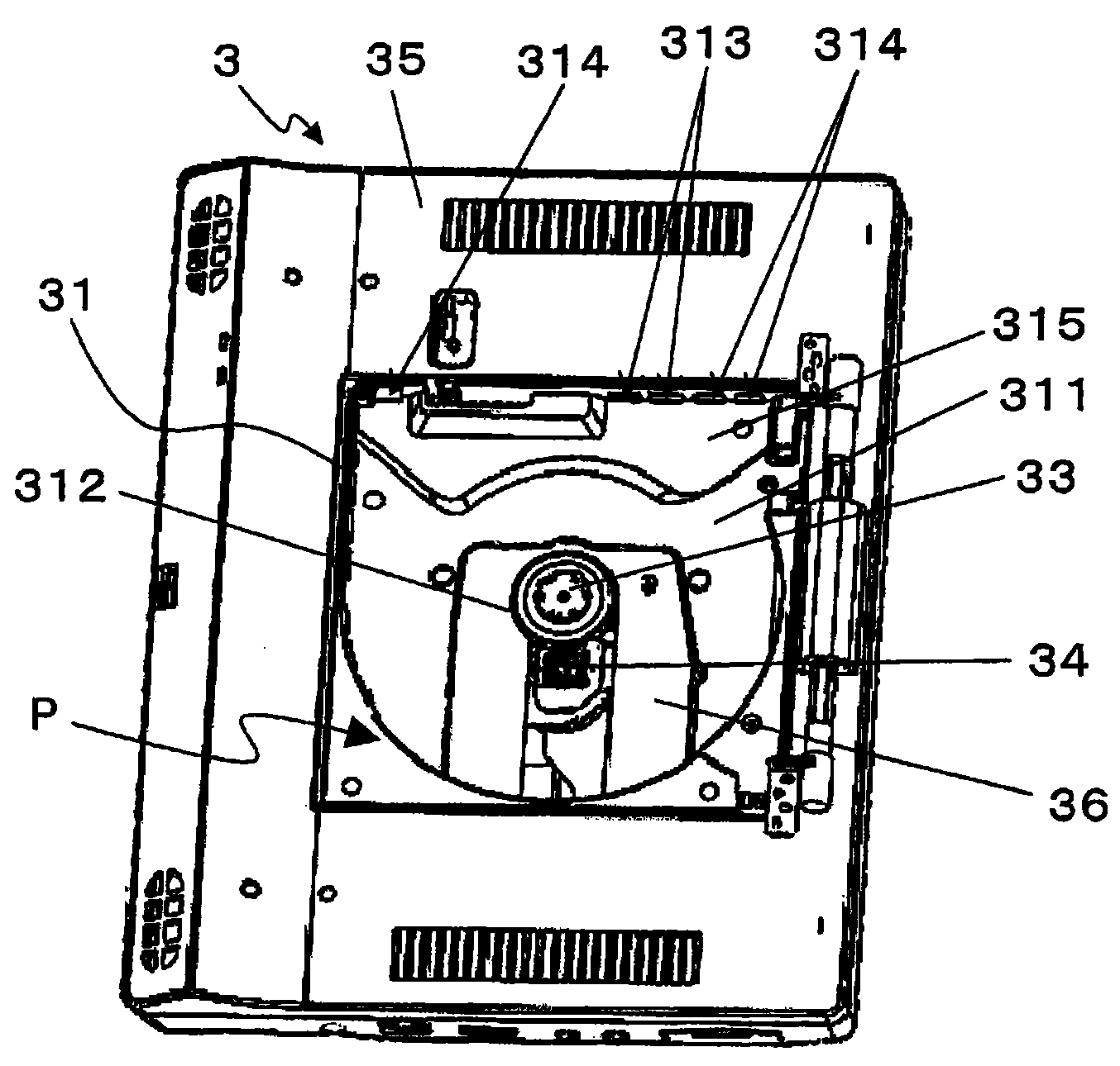
图3B是表示将盖取下后的第二框体的主视图。Fig. 3B is a front view showing the second housing with the cover removed.
图4A是表示第二框体的内部的立体图。Fig. 4A is a perspective view showing the inside of the second housing.
图4B是表示第二框体的内部的主视图。Fig. 4B is a front view showing the inside of the second housing.
图5是收纳部的局部放大图。Fig. 5 is a partial enlarged view of the storage section.
图6A是说明风从吸气流路向第一排气流路流动的示意图。FIG. 6A is a schematic diagram illustrating the flow of wind from the intake flow path to the first exhaust flow path.
图6B是说明风从吸气流路向第二排气流路流动的示意图。FIG. 6B is a schematic diagram illustrating the flow of wind from the intake flow path to the second exhaust flow path.
图7是从上方观察第二框体时的示意图。Fig. 7 is a schematic view of the second housing viewed from above.
具体实施方式Detailed ways
利用附图说明本发明的一实施方式。本实施方式的再生设备为读取光盘信息的电子设备的一例。One embodiment of the present invention will be described with reference to the drawings. The playback device of this embodiment is an example of an electronic device that reads information from an optical disc.
图1是表示本实施方式的再生设备1的立体图。图2是表示本实施方式的再生设备1的第二框体3的立体图。图3A是表示在第二框体3中,将收纳光盘的收纳部31的盖32取下后的状态的立体图,图3B是其主视图。图4A是表示第二框体3的内部结构的立体图,图4B是其主视图。图5是收纳部31的局部放大图。FIG. 1 is a perspective view showing a
另外,在本实施方式中,称图3B所示的z轴的正方向(收纳的光盘的信息记录面的相反面侧的方向)为上方,称z轴的负方向(搭载的光盘的信息记录面侧的方向)为下方。In addition, in this embodiment, the positive direction of the z-axis shown in FIG. 3B (direction on the opposite side of the information recording surface of the stored optical disc) is referred to as upward, and the negative direction of the z-axis (the direction of the information recording surface of the loaded optical disc) is referred to as upward. The direction of the face side) is downward.
<1.再生设备1的结构的大致说明><1. Outline description of the structure of the
如图1及图2所示,再生设备1具有第一框体2、第二框体3、腿部4、第一换气口5及第二换气口6。As shown in FIGS. 1 and 2 , the
第一框体2与第二框体3由连结部22物理连接。第一框体2与第二框体3以连结部22为支点可动。此外,第一框体2与第二框体3电连接。The
第一框体2具备液晶组件21。第二框体3具备收纳光盘(例如,CD、DVD、BD等)的收纳部31和覆盖收纳部31的盖32。收纳部31被盖32覆盖而收纳由轴机构33保持的光盘。从光盘读出的记录信息从第二框体3向第一框体2传送,在液晶组件21上显示。这样的从光盘读取记录信息并显示的结构是现有技术,因此省略详细说明。The
腿部4隔着第二框体3设置在第一框体2的相反侧。通过打开腿部4,能够将再生设备1以竖起的状态使用。在此需要说明的是,腿部4在图2~图3B中省略。The
第一换气口5及第二换气口6是用于在第二框体3的内部与第二框体3的外部之间进行换气的开口。第一换气口5及第二换气口6具有作为吸气口的功能和作为排气口的功能。The
<2.第二框体3的结构的具体说明><2. Specific description of the structure of the
第二框体3能够从收纳的光盘读出记录信息并向第一框体2输出。如图3所示,第二框体3具备收纳光盘的收纳部31和构成第二框体3的外装的外装部35。收纳部31与外装部35可以一体地形成,也可以由不同的构件构成。The
如图3A所示,收纳部31形成收纳光盘的收纳空间P。收纳部31具有:保持光盘且使其旋转的轴机构33;从通过轴机构33而旋转的光盘读出记录信息的拾光器34;将拾光器34支承为可动的机械部36。As shown in FIG. 3A , the
轴机构33具备主轴电动机等。拾光器34由激光、检测器、PBS、物镜等构成。机械部36具有促动器、驱动器,且被支承为在沿拾光器341的轴向上可动。The
另外,收纳部31具有:与保持在轴机构33上的光盘对置的载置部311;形成于轴机构33的外周且与后述的第一内部空间Q相连的吸气流路312;与后述的第二内部空间R相连的第一排气流路313;与第二框体3(再生设备1)的外部空间相连的第二排气流路314。In addition, the
另外,第二框体3的内部为如下结构。如图4所示,在收纳部31的下方设置有用于控制轴机构33、拾光器34及机械部36的IC芯片381和用于控制再生设备1的电源的电源部件382。IC芯片381与轴机构33、拾光器34、机械部36电连接。In addition, the inside of the
IC芯片381配置于形成在收纳部31外的第一内部空间Q中。收纳空间P与第一内部空间Q被载置部311及机械部36隔开。此外,电源部件382配置在以包围第一内部空间Q的方式形成于收纳部31外的第二内部空间R中。第一内部空间Q与收纳空间P由吸气流路312连结。The
另外,在电源部件382与拾光器34之间设置有肋383,用来防止电源部件382的起火蔓延燃烧到机械部36。肋383由难燃性的构件构成,其突出设置在外装部35的底面。In addition, a
在此,在本实施方式中,第一内部空间Q与第二内部空间R被肋383隔开。第二内部空间R与收纳空间P由第一排气流路313连结。Here, in the present embodiment, the first internal space Q and the second internal space R are separated by the
如图4A及图4B所示,管道37与第二排气流路314和第二框体3的外部空间连通。管道37具有朝向外部空间形成的外装开口部371。如图5所示,管道37沿着在光盘的旋转作用下空气流动的方向(即,回旋流的行进方向)形成。即,在管道37中,如图3B及图4B所示,外装开口部371在x方向上比第二排气流路314更远离轴机构33。由此,空气不会逆着回旋流的流动而排出,因此能够更加有效地促进散热。其中,回旋流是指由光盘的旋转而产生的空气的流动。空气在载置部311与光盘之间从轴机构33向径向外方回旋的同时流动(参照图6A及图6B)。As shown in FIGS. 4A and 4B , the
此外,载置部311具有将回旋流向第一排气流路313及第二排气流路314引导的导流部315。导流部315是载置部311中的与第一排气流路313及第二排气流路314的开口部相连的区域。如图5所示。导流部315通过使载置部311的一部分向下方凹陷而形成。由此,能够将第一排气流路313及第二排气流路314的开口与没有导流部315的情况相比形成得更大。此外,导流部315优选经由平缓地倾斜的边界部316而凹陷。若如此,则能够抑制回旋流在边界部316产生旋涡,因此能够使回旋流更加顺畅地回旋。其结果是,能够更有效地促进散热。Furthermore, the mounting
此外,在导流部315中形成有凸部317。凸部317在与装载的光盘的信息记录面的外周对置的位置形成。在形成有导流部315的情况下,若在装载光盘时对光盘施加按压,则可能在边界部316损伤信息记录面。凸部317通过在按压光盘时与外周相接来防止边界部316与光盘的信息记录面相接。即,凸部317降低在边界部316损伤光盘的信息记录面的可能。In addition, a
此外,如图5所示,在收纳部31的内壁面上形成有与第二内部空间R相连的多个第三排气流路318。由此,收纳空间P与第二内部空间R不仅由第一排气流路313连结,还通过多个第三排气流路318连结。In addition, as shown in FIG. 5 , a plurality of third
<3.第二框体3动作时的风的流动><3. Flow of wind when the
说明第二框体3在使光盘旋转时产生的风的流动。The flow of wind generated when the
图6A及图6B分别为用于说明风的流动的再生设备1的剖面示意图。并且,为了容易理解,图6A及图6B分别仅示意地示出大致结构。图6A是说明从风从吸气流路312向第一排气流路313流动的示意图。此外,图6B是说明风从吸气流路312向第二排气流路314流动的示意图。6A and 6B are schematic cross-sectional views of the regenerating
在图6A中,当光盘D旋转时,空气从配置有IC芯片381的第一内部空间Q经由吸气流路312吸入到收纳空间P(具体地说,载置部311与光盘D之间)。该空气的流动在图中由箭头A1表示。从吸气流路312吸入的空气在由光盘D的旋转而产生的离心力的作用下成为回旋流。该回旋流在向光盘D的旋转方向同方向回旋的同时从光盘D的内侧向外侧流动。该空气的流动在图中由箭头A2表示。从吸气流路312吸入的空气乘载于回旋流在导流部315上流动而流入第一排气流路313。流入第一排气流路313的空气向第二内部空间R流入,使第二内部空间R内的热量扩散。该空气的流动在图中由箭头A3表示。In FIG. 6A, when the optical disk D rotates, air is sucked from the first internal space Q where the
通过上述的空气的流动,能够使第一内部空间Q的空气与第二内部空间R的空气有效地扩散。即,由于能够减少在再生设备1内部产生的热点,因此能够有效地促进再生设备1内部的散热。The air in the first interior space Q and the air in the second interior space R can be effectively diffused by the air flow described above. That is, since hot spots generated inside the
在图6B中,当光盘D旋转时,空气从第一内部空间Q经由吸气流路312吸入到收纳空间P。该空气的流动在图中由箭头B1表示所示。从吸气流路312吸入的空气在由光盘D的旋转而产生的离心力的作用下成为回旋流。该回旋流在向与光盘D的旋转方向同方向回旋的同时从光盘D的内侧向外侧流动。该空气的流动在图中由箭头B2表示。从吸气流路312吸入的空气乘载于回旋流在导流部315上流动而流入第二排气流路314。流入第二排气流路314的空气流过管道37而向外部空间排出。该空气的流动在图中由箭头B3表示。In FIG. 6B , when the optical disk D rotates, air is sucked from the first internal space Q into the storage space P through the
通过如上所述的空气的流动,能够有效地将第一内部空间Q的空气向第二框体3的外部空间排出。由此,能够有效地促进再生设备1内部的散热。Through the flow of air as described above, the air in the first internal space Q can be efficiently discharged to the external space of the
在本实施方式的再生设备1中,同时具有如图6A及图6B所示的那样的两股空气的流动。另外,在重视第二内部空间R中的热扩散时,也可以作为排气流路仅形成第一排气流路313。此外,在重视第一内部空间Q中的废热时,也可以作为排气流路仅形成第二排气流路314。In the
在此,图7是用于说明空气的流动的、从上方观察第二框体3时的示意图。在收纳空间P中,在机械部36、拾光器34的附近,由于凹凸、间隙的影响而容易产生乱流。但是,第一排气流路313及第二排气流路314隔着轴机构33形成在拾光器34的相反侧。更详细地说,第一排气流路313或第二排气流路314在从收纳部31的上方观察时形成在角θ成钝角的位置,其中角θ是连结第一排气流路313或第二排气流路314与轴机构33的中心的线和连结拾光器34与轴机构33的中心的线所成的角。换言之,在从收纳部31的上方观察时,第一排气流路或第二排气流路隔着通过轴机构33的中心且与连结拾光器34和轴机构33的中心的线正交的线P形成在拾光器34的相反侧。由此,第一排气流路313及第二排气流路314形成在不易受紊流影响的部位,因此能够有效地从第一排气流路313及第二排气流路314进行排气。Here, FIG. 7 is a schematic diagram for explaining the flow of air, when the
此外,通过使载置部311在导流部315凹陷,从而能够将第一排气流路313及第二排气流路314形成得更大。即,能够增加排气的流量。其结果是,能够更有效地促进散热。In addition, the first
另外,在本实施方式中,IC芯片381是第一电子部件的一例。此外,电源部件382是第二电子部件的一例。此外,肋383是壁部的一例。In addition, in this embodiment, the
另外,在本实施方式中,与电源部件382相比,IC芯片381在规定的期间的发热量变大。在这样的情况下,能够从发热量大的IC芯片381周边吸收热气,向发热量小的电源部件382排出,因此能够实现热量的平均化。由此,能够有效地排出主体内的电子部件的热量。In addition, in the present embodiment, the amount of heat generated by the
工业上的可利用性Industrial availability
本发明的电子设备能够适用于DVD播放器、DVD记录器、BD播放器、BD记录器等读取光盘的信息的设备。The electronic device of the present invention can be applied to a device for reading information from an optical disc, such as a DVD player, a DVD recorder, a BD player, and a BD recorder.
符号说明Symbol Description
1再生设备1 regeneration equipment
2第一框体2 first frame
3第二框体3 second frame
4腿部4 legs
5第一换气口5 first ventilation port
6第二换气口6 second air vent
21液晶组件21 LCD components
31收纳部31 storage department
311载置部311 loading part
312吸气流路312 suction flow path
313第一排气流路313 The first exhaust flow path
314第二排气流路314 Second exhaust flow path
318第三排气流路318 The third exhaust flow path
315导流部315 Diversion Department
316边界部316 Boundary Department
317凸部317 Convex
32盖32 caps
33轴机构33 axis mechanism
34拾光器34 optical pickups
35外装部35 Exterior Department
36机械部36 Mechanical Department
37管道37 pipes
371外装开口部371 exterior opening
381IC芯片381IC chip
382电源部件382 Power Parts
383肋383 ribs
P收纳空间P storage space
Q第一内部空间Q first interior space
R第二内部空间R second inner space
权利要求书(按照条约第19条的修改)Claims (as amended under Article 19 of the Treaty)
1.(修改后)一种电子设备,其中,1. (Modified) An electronic device wherein,
具备收纳光盘的框体,With a frame for storing discs,
所述框体具备:The frame has:
收纳光盘的收纳空间;Storage space for storing CDs;
设置在所述收纳空间中,保持所述光盘且使该光盘旋转的旋转保持部;a rotation holder for holding and rotating the optical disk provided in the storage space;
可动地设置在所述收纳空间中且读取所述光盘的记录数据的拾取部;a pick-up part that is movably arranged in the storage space and reads the recorded data of the optical disc;
与所述收纳空间隔开且配置对所述拾取部进行控制的第一电子部件的第一内部空间;a first internal space separated from the storage space and configured with a first electronic component that controls the pick-up unit;
从所述第一内部空间向所述收纳空间连接的吸气流路;an inhalation flow path connected from the first internal space to the storage space;
从所述收纳空间向与所述第一内部空间不同的规定空间连接的排气流路;an exhaust flow path connected from the storage space to a predetermined space different from the first internal space;
设置在所述收纳空间中且与保持在所述旋转保持部上的所述光盘对置的载置部;a mounting portion provided in the storage space and facing the optical disc held on the rotation holding portion;
使所述载置部的一部分凹陷而形成且与所述排气流路相连的导流部。A flow guide part is formed by recessing a part of the mounting part and is connected to the exhaust flow path.
2.根据权利要求1所述的电子设备,其中,2. The electronic device according to
在所述收纳空间中,所述吸气流路比所述排气流路接近所述旋转保持部开口。In the storage space, the intake flow path is closer to the rotation holding portion opening than the exhaust flow path.
3.根据权利要求1或2所述的电子设备,其中,具备:3. The electronic device according to
与所述收纳空间隔开且配置第二电子部件的第二内部空间;a second internal space separated from the storage space and configured with second electronic components;
隔开所述第一内部空间与所述第二内部空间的壁部,a wall separating the first interior space from the second interior space,
所述规定空间为所述第二内部空间。The predetermined space is the second internal space.
4.根据权利要求3所述的电子设备,其中,4. The electronic device according to
所述第一电子部件比所述第二电子部件在规定期间的平均发热量大。The average calorific value of the first electronic component is larger than that of the second electronic component during a predetermined period.
5.根据权利要求1或2所述的电子设备,其中,5. The electronic device according to
所述规定空间是所述框体的外部空间。The predetermined space is an external space of the housing.
6.根据权利要求5所述的电子设备,其中,6. The electronic device according to
具备与所述排气流路和所述外部空间连通的管道,having a pipe communicating with the exhaust flow path and the external space,
所述管道沿着通过所述光盘的旋转而空气流动的方向形成。The duct is formed along a direction in which air flows through the rotation of the optical disk.
7.根据权利要求1所述的电子设备,其中,7. The electronic device according to
连结所述排气流路与所述旋转保持部的中心的线和连结所述拾取部与所述旋转保持部的中心的线所成的角是钝角。An angle formed by a line connecting the exhaust flow path and the center of the rotation holding part and a line connecting the pick-up part and the center of the rotation holding part is an obtuse angle.
8.(删除)8. (deleted)
9.(追加)根据权利要求1所述的电子设备,其中,9. (additional) The electronic device according to
所述导流部经由平缓地倾斜的边界部使所述载置部的一部分凹陷而形成。The flow guide part is formed by denting a part of the mounting part through a gently inclined boundary part.
10.(追加)根据权利要求1所述的电子设备,其中,10. (additional) The electronic device according to
所述导流部具有在与被收纳的所述光盘的信息记录面的外周对置的位置形成的凸部。The flow guide part has a convex part formed at a position facing the outer periphery of the information recording surface of the stored optical disc.
Claims (8)
Applications Claiming Priority (5)
| Application Number | Priority Date | Filing Date | Title |
|---|---|---|---|
| JP2009001399 | 2009-01-07 | ||
| JP2009002301 | 2009-01-08 | ||
| JP2009-002301 | 2009-01-08 | ||
| JP2009-001399 | 2009-03-10 | ||
| PCT/JP2010/000004 WO2010079732A1 (en) | 2009-01-07 | 2010-01-04 | Electronic device |
Publications (2)
| Publication Number | Publication Date |
|---|---|
| CN102089825A true CN102089825A (en) | 2011-06-08 |
| CN102089825B CN102089825B (en) | 2013-09-04 |
Family
ID=42316497
Family Applications (1)
| Application Number | Title | Priority Date | Filing Date |
|---|---|---|---|
| CN2010800020560A Expired - Fee Related CN102089825B (en) | 2009-01-07 | 2010-01-04 | Electronic device |
Country Status (4)
| Country | Link |
|---|---|
| US (1) | US8584152B2 (en) |
| JP (1) | JP4643762B2 (en) |
| CN (1) | CN102089825B (en) |
| WO (1) | WO2010079732A1 (en) |
Families Citing this family (2)
| Publication number | Priority date | Publication date | Assignee | Title |
|---|---|---|---|---|
| CN102568536A (en) * | 2010-12-31 | 2012-07-11 | 鸿富锦精密工业(深圳)有限公司 | Compact disk player |
| EP3499339B1 (en) * | 2017-12-13 | 2021-11-24 | Vestel Elektronik Sanayi ve Ticaret A.S. | Electronics device and method of cooling |
Citations (4)
| Publication number | Priority date | Publication date | Assignee | Title |
|---|---|---|---|---|
| JP2003151259A (en) * | 2001-11-09 | 2003-05-23 | Hitachi-Lg Data Storage Inc | Optical disk drive |
| JP2003249070A (en) * | 2002-02-21 | 2003-09-05 | Toshiba Corp | Disk drive unit, electronic apparatus, and cooling disk |
| CN1866388A (en) * | 2005-05-20 | 2006-11-22 | 日立乐金资料储存股份有限公司 | Optical disc device |
| JP2007172799A (en) * | 2005-12-26 | 2007-07-05 | Pioneer Electronic Corp | Disk device |
Family Cites Families (24)
| Publication number | Priority date | Publication date | Assignee | Title |
|---|---|---|---|---|
| JPH04330694A (en) | 1991-05-01 | 1992-11-18 | Fujitsu Ltd | optical disc device |
| JP3023718B2 (en) | 1991-07-26 | 2000-03-21 | 株式会社フジタ | Building construction method and equipment |
| US5493457A (en) * | 1991-10-18 | 1996-02-20 | Matsushita Electric Industrial Co., Ltd. | Optical disk apparatus with cooling arrangement |
| US5200945A (en) * | 1992-01-07 | 1993-04-06 | International Business Machines Corporation | Optical data storage system with airflow defecting member |
| US5813243A (en) * | 1997-04-04 | 1998-09-29 | Micron Electronics, Inc. | Chambered forced cooling system |
| JP2001155479A (en) | 1999-11-25 | 2001-06-08 | Sony Corp | Disk device |
| JP2003085964A (en) | 2001-09-14 | 2003-03-20 | Ricoh Co Ltd | Optical disk device |
| US6826768B2 (en) * | 2002-10-08 | 2004-11-30 | Micro-Star Int'l Co., Ltd. | Optical compact disk drive with a vibration-and-noise attenuating mechanism |
| JP2004241024A (en) | 2003-02-04 | 2004-08-26 | Shinano Kenshi Co Ltd | Disk drive |
| KR100510536B1 (en) * | 2003-07-23 | 2005-08-26 | 삼성전자주식회사 | A optical disk drive using noise reduction means |
| TW200516562A (en) * | 2003-11-06 | 2005-05-16 | Benq Corp | Optical disk drive capable of dissipating heat and proofing against dust |
| JP4069877B2 (en) * | 2004-02-03 | 2008-04-02 | ソニー株式会社 | Electronic device and hard disk drive storage device |
| TWI245277B (en) * | 2004-03-23 | 2005-12-11 | Lite On It Corp | A cooling device used in an optical recording and/or reproducing apparatus |
| JP2006040376A (en) | 2004-07-26 | 2006-02-09 | Sony Corp | Heat radiation apparatus of electronic equipment for disk, and heat radiation method of electronic equipment for disk |
| JP4324570B2 (en) * | 2005-02-15 | 2009-09-02 | 株式会社日立製作所 | Optical disk device |
| US7430748B2 (en) * | 2005-06-16 | 2008-09-30 | Quanta Storage Inc. | Noise reducing optical disc drive |
| JP2007004894A (en) | 2005-06-23 | 2007-01-11 | Toshiba Corp | Electronic device |
| TWI270864B (en) * | 2005-06-30 | 2007-01-11 | Lite On It Corp | Disk recording/reading apparatus |
| CN100592240C (en) * | 2005-10-28 | 2010-02-24 | 鸿富锦精密工业(深圳)有限公司 | Heat sink and note-book computer with the heat sink |
| US7885062B2 (en) * | 2005-12-09 | 2011-02-08 | Nvidia Corporation | Computer chassis with partitions for improved airflow |
| JP2007172744A (en) * | 2005-12-22 | 2007-07-05 | Hitachi Ltd | Disk drive |
| JP4769125B2 (en) * | 2006-05-29 | 2011-09-07 | 株式会社日立製作所 | Disk unit |
| JP4167700B2 (en) | 2006-05-31 | 2008-10-15 | 株式会社東芝 | Electronics |
| JP2008016067A (en) | 2006-06-30 | 2008-01-24 | Ricoh Co Ltd | Optical disk device |
-
2010
- 2010-01-04 WO PCT/JP2010/000004 patent/WO2010079732A1/en active Application Filing
- 2010-01-04 CN CN2010800020560A patent/CN102089825B/en not_active Expired - Fee Related
- 2010-01-04 JP JP2010522109A patent/JP4643762B2/en not_active Expired - Fee Related
- 2010-01-04 US US13/056,808 patent/US8584152B2/en not_active Expired - Fee Related
Patent Citations (4)
| Publication number | Priority date | Publication date | Assignee | Title |
|---|---|---|---|---|
| JP2003151259A (en) * | 2001-11-09 | 2003-05-23 | Hitachi-Lg Data Storage Inc | Optical disk drive |
| JP2003249070A (en) * | 2002-02-21 | 2003-09-05 | Toshiba Corp | Disk drive unit, electronic apparatus, and cooling disk |
| CN1866388A (en) * | 2005-05-20 | 2006-11-22 | 日立乐金资料储存股份有限公司 | Optical disc device |
| JP2007172799A (en) * | 2005-12-26 | 2007-07-05 | Pioneer Electronic Corp | Disk device |
Also Published As
| Publication number | Publication date |
|---|---|
| JPWO2010079732A1 (en) | 2012-06-21 |
| US20110138406A1 (en) | 2011-06-09 |
| US8584152B2 (en) | 2013-11-12 |
| WO2010079732A1 (en) | 2010-07-15 |
| CN102089825B (en) | 2013-09-04 |
| JP4643762B2 (en) | 2011-03-02 |
Similar Documents
| Publication | Publication Date | Title |
|---|---|---|
| CN102089825B (en) | Electronic device | |
| JP4102824B2 (en) | Optical disk device | |
| US20070150909A1 (en) | Disc drive | |
| TWI264710B (en) | Disc apparatus | |
| JPWO2007077709A1 (en) | Disk unit | |
| CN101859576B (en) | CD device | |
| JP4724403B2 (en) | Disc player | |
| JP2018129110A (en) | Optical disk drive, information expansion device, and information recording device | |
| US20080155578A1 (en) | Optical Disk Drive Unit Having a Cooling Device | |
| US20050102690A1 (en) | Optical disk drive capable of dissipating heat and proofing against dust | |
| JP4768435B2 (en) | Disk unit | |
| JP4206424B2 (en) | Optical disk device | |
| JP6365166B2 (en) | Optical disc apparatus, optical pickup cleaning method, and server | |
| JP4687261B2 (en) | Disk drive device and electronic device | |
| TWI451409B (en) | Optical disc drive | |
| JP2005353114A (en) | Disk drive | |
| JP4893604B2 (en) | Disk drive | |
| JP2008103018A (en) | Heat source cooling mechanism and electric apparatus | |
| JP2007323748A (en) | Disk driving device | |
| JP2008217923A (en) | Disk device | |
| JP2008262644A (en) | Vcr incorporated optical disk drive | |
| WO2014073129A1 (en) | Optical disc apparatus, sheet member, and method for cleaning objective lens | |
| JP2009301673A (en) | Optical disk device | |
| JP2009140602A (en) | Optical disk device | |
| JP2006260628A (en) | Optical disk player |
Legal Events
| Date | Code | Title | Description |
|---|---|---|---|
| C06 | Publication | ||
| PB01 | Publication | ||
| C10 | Entry into substantive examination | ||
| SE01 | Entry into force of request for substantive examination | ||
| C14 | Grant of patent or utility model | ||
| GR01 | Patent grant | ||
| CF01 | Termination of patent right due to non-payment of annual fee | ||
| CF01 | Termination of patent right due to non-payment of annual fee |
Granted publication date: 20130904 Termination date: 20200104 |