CN102066882A - Method and device for detecting the volume of gas in a pipeline - Google Patents
Method and device for detecting the volume of gas in a pipeline Download PDFInfo
- Publication number
- CN102066882A CN102066882A CN2009801227927A CN200980122792A CN102066882A CN 102066882 A CN102066882 A CN 102066882A CN 2009801227927 A CN2009801227927 A CN 2009801227927A CN 200980122792 A CN200980122792 A CN 200980122792A CN 102066882 A CN102066882 A CN 102066882A
- Authority
- CN
- China
- Prior art keywords
- capacitance
- capacitor
- fluid line
- fluid
- detected
- Prior art date
- Legal status (The legal status is an assumption and is not a legal conclusion. Google has not performed a legal analysis and makes no representation as to the accuracy of the status listed.)
- Pending
Links
Images


Classifications
-
- G—PHYSICS
- G01—MEASURING; TESTING
- G01N—INVESTIGATING OR ANALYSING MATERIALS BY DETERMINING THEIR CHEMICAL OR PHYSICAL PROPERTIES
- G01N27/00—Investigating or analysing materials by the use of electric, electrochemical, or magnetic means
- G01N27/02—Investigating or analysing materials by the use of electric, electrochemical, or magnetic means by investigating impedance
- G01N27/22—Investigating or analysing materials by the use of electric, electrochemical, or magnetic means by investigating impedance by investigating capacitance
-
- G—PHYSICS
- G01—MEASURING; TESTING
- G01F—MEASURING VOLUME, VOLUME FLOW, MASS FLOW OR LIQUID LEVEL; METERING BY VOLUME
- G01F1/00—Measuring the volume flow or mass flow of fluid or fluent solid material wherein the fluid passes through a meter in a continuous flow
- G01F1/704—Measuring the volume flow or mass flow of fluid or fluent solid material wherein the fluid passes through a meter in a continuous flow using marked regions or existing inhomogeneities within the fluid stream, e.g. statistically occurring variations in a fluid parameter
- G01F1/708—Measuring the time taken to traverse a fixed distance
- G01F1/712—Measuring the time taken to traverse a fixed distance using auto-correlation or cross-correlation detection means
-
- A—HUMAN NECESSITIES
- A61—MEDICAL OR VETERINARY SCIENCE; HYGIENE
- A61M—DEVICES FOR INTRODUCING MEDIA INTO, OR ONTO, THE BODY; DEVICES FOR TRANSDUCING BODY MEDIA OR FOR TAKING MEDIA FROM THE BODY; DEVICES FOR PRODUCING OR ENDING SLEEP OR STUPOR
- A61M5/00—Devices for bringing media into the body in a subcutaneous, intra-vascular or intramuscular way; Accessories therefor, e.g. filling or cleaning devices, arm-rests
- A61M5/14—Infusion devices, e.g. infusing by gravity; Blood infusion; Accessories therefor
- A61M5/168—Means for controlling media flow to the body or for metering media to the body, e.g. drip meters, counters ; Monitoring media flow to the body
-
- A—HUMAN NECESSITIES
- A61—MEDICAL OR VETERINARY SCIENCE; HYGIENE
- A61M—DEVICES FOR INTRODUCING MEDIA INTO, OR ONTO, THE BODY; DEVICES FOR TRANSDUCING BODY MEDIA OR FOR TAKING MEDIA FROM THE BODY; DEVICES FOR PRODUCING OR ENDING SLEEP OR STUPOR
- A61M5/00—Devices for bringing media into the body in a subcutaneous, intra-vascular or intramuscular way; Accessories therefor, e.g. filling or cleaning devices, arm-rests
- A61M5/36—Devices for bringing media into the body in a subcutaneous, intra-vascular or intramuscular way; Accessories therefor, e.g. filling or cleaning devices, arm-rests with means for eliminating or preventing injection or infusion of air into body
- A61M5/365—Air detectors
-
- A—HUMAN NECESSITIES
- A61—MEDICAL OR VETERINARY SCIENCE; HYGIENE
- A61M—DEVICES FOR INTRODUCING MEDIA INTO, OR ONTO, THE BODY; DEVICES FOR TRANSDUCING BODY MEDIA OR FOR TAKING MEDIA FROM THE BODY; DEVICES FOR PRODUCING OR ENDING SLEEP OR STUPOR
- A61M2205/00—General characteristics of the apparatus
- A61M2205/33—Controlling, regulating or measuring
- A61M2205/3317—Electromagnetic, inductive or dielectric measuring means
Landscapes
- Health & Medical Sciences (AREA)
- Life Sciences & Earth Sciences (AREA)
- General Physics & Mathematics (AREA)
- Physics & Mathematics (AREA)
- General Health & Medical Sciences (AREA)
- Veterinary Medicine (AREA)
- Vascular Medicine (AREA)
- Hematology (AREA)
- Biomedical Technology (AREA)
- Animal Behavior & Ethology (AREA)
- Anesthesiology (AREA)
- Public Health (AREA)
- Engineering & Computer Science (AREA)
- Fluid Mechanics (AREA)
- Heart & Thoracic Surgery (AREA)
- Emergency Medicine (AREA)
- Chemical & Material Sciences (AREA)
- Electrochemistry (AREA)
- Chemical Kinetics & Catalysis (AREA)
- Analytical Chemistry (AREA)
- Biochemistry (AREA)
- Immunology (AREA)
- Pathology (AREA)
- Investigating Or Analyzing Materials By The Use Of Electric Means (AREA)
- Measuring Volume Flow (AREA)
- Measurement Of Levels Of Liquids Or Fluent Solid Materials (AREA)
Abstract
Description
技术领域technical field
本发明总的涉及监控管路中的流体而不直接接触流体,更具体地说,涉及非干涉地监控流体性质的变化,包括空气或其他气体的存在。The present invention relates generally to monitoring fluid in pipelines without direct contact with the fluid, and more particularly to non-intrusively monitoring changes in fluid properties, including the presence of air or other gases.
背景技术Background technique
在许多医疗和工业应用中,为了确保处理的一致性或确保安全,对流体的连续的管路中(in-line)的监控通常是必需的。例如,管路中的流体压力对于处理可能是关键性的。此外,可能需要监控流体内的空气或其他气体的存在或流体内的污染物的存在。In many medical and industrial applications, continuous in-line monitoring of fluids is often required to ensure consistency of treatment or to ensure safety. For example, the fluid pressure in the line may be critical to the process. Additionally, it may be desirable to monitor the fluid for the presence of air or other gases or the presence of contaminants within the fluid.
在医疗场合,管路中的气体的检测系统用于防止气体无意中注入病人的血流中。虽然很小的气泡可能对病人没有负面影响,但是大气泡能够引起空气栓塞,导致疼痛或死亡。用于气体的管路中检测的方法通常包括通过被监控的流体管路的超声波或光传输。声音或光通过流体和气体的不同传输特性可以用来形成在流体管路的液体中存在气泡的指示。来自这种传感器的简单可识别的信号干扰可以用来触发报警和/或阻挡注入。这种系统要求流体和相关的导管对于被传输的能量基本是可穿透的。In medical settings, gas detection systems in tubing are used to prevent inadvertent injection of gas into a patient's bloodstream. While very small air bubbles may have no negative impact on the patient, large air bubbles can cause air embolisms, leading to pain or death. Methods for in-line detection of gases typically involve ultrasonic or optical transmission through the fluid line being monitored. The different transmission properties of sound or light through fluids and gases can be used to form an indication of the presence of gas bubbles in the liquid of the fluid line. Simply identifiable signal disturbances from such sensors can be used to trigger alarms and/or block injection. Such systems require that the fluid and associated conduits be substantially penetrable to the energy being transmitted.
在一个示范性的实施例中,兆赫(MHz)范围内的超声波能量耦联在被测试的导管的一侧上,而接收器设置在相对侧上。当导管中存在气泡时,能量从发射侧到接收侧衰减。当导管中存在流体时,在接收器中接收的能量大大增加。这种能量或信号强度因此可以用作指示器,以确定导管中是否存在气体。此外,如果流体速率是已知的,则能够确定气泡尺寸并且可以设置阈值,以当气泡超过预定的限度时给出指示,因而触发报警。In an exemplary embodiment, ultrasonic energy in the megahertz (MHz) range is coupled on one side of the catheter under test and a receiver is positioned on the opposite side. When air bubbles are present in the conduit, the energy decays from the transmitting side to the receiving side. The energy received in the receiver is greatly increased when fluid is present in the conduit. This energy or signal strength can thus be used as an indicator to determine whether gas is present in the catheter. Furthermore, if the fluid velocity is known, the bubble size can be determined and thresholds can be set to give an indication when bubbles exceed predetermined limits, thus triggering an alarm.
但是,气泡经常不以与流体相同的速率移动,使气泡被认为比它实际的大,产生虚假的或令人厌烦的报警。这可以由附着在导管侧上的“泰勒(Taylor)”型气泡或“香槟”型气泡引起,引起足够的衰减从而产生报警。此外,超声波或光学的管路中气体检测器通常不能确定气泡的确切尺寸并且被配置成仅仅指示大于预定尺寸气泡的存在。However, air bubbles often do not move at the same rate as the fluid, causing the air bubble to be perceived as larger than it actually is, creating false or annoying alarms. This can be caused by "Taylor" type air bubbles or "Champagne" type air bubbles adhering to the side of the catheter, causing sufficient attenuation to generate an alarm. Furthermore, ultrasonic or optical in-line gas detectors are generally unable to determine the exact size of gas bubbles and are configured to only indicate the presence of gas bubbles larger than a predetermined size.
能够检测流体内的诸如气体的夹杂物的其他设备包括光学系统。但是,与这种光学系统一起使用的图像处理使这种选择过于昂贵。Other devices capable of detecting inclusions such as gases within fluids include optical systems. However, the image processing used with such optical systems makes this option prohibitively expensive.
发明内容Contents of the invention
需要一种管路中流体监控系统和方法,这种系统和方法不涉及流体与传感器直接接触,但是对于流体组成中的各种变化(包括空气或其他气体的存在)具有较高的灵敏度,并且能够提供气泡尺寸的指示。在医疗系统中,需要一种可靠地并且精确地检测并量化管路中气体或其他夹杂物的存在,同时相对廉价并且能够与廉价的一次性使用的流体管路一起使用的设备和方法。There is a need for an in-line fluid monitoring system and method that does not involve direct contact of the fluid with a sensor, but has high sensitivity to changes in fluid composition, including the presence of air or other gases, and Capable of providing an indication of bubble size. In medical systems, there is a need for an apparatus and method that reliably and accurately detects and quantifies the presence of gas or other inclusions in tubing, while being relatively inexpensive and capable of being used with inexpensive single-use fluid tubing.
当前公开的实施例涉及解决上面所述的现有技术中存在的一个或多个问题,并且提供附加的特征,这些附加的特征当通过连同附图一起参考下面的详细描述时容易变得很明白。The presently disclosed embodiments are directed to solving one or more of the problems of the prior art described above, and to providing additional features which will become readily apparent when reference is made to the following detailed description in conjunction with the accompanying drawings. .
一个或更多个优选实施例涉及用于不直接接触流体的监控管道中的流体的方法。提供对流体性质的检测,包括空气或其他气体的存在以及对流体成分中的变化的指示。该方法包括使流体通过流体管路,其中该流体管路至少部分地被第一电容器围绕,并且在该第一电容器处检测该流体管路的电容。该方法还包括将在第一电容器处检测到的电容与参考电容进行比较并且根据在第一电容器处检测到的电容与参考电容的比较确定流体管路中是否存在气体。One or more preferred embodiments relate to a method for monitoring a fluid in a pipeline without direct contact with the fluid. Provides detection of fluid properties, including the presence of air or other gases, and indications of changes in fluid composition. The method includes passing fluid through a fluid line, wherein the fluid line is at least partially surrounded by a first capacitor, and detecting a capacitance of the fluid line at the first capacitor. The method also includes comparing the detected capacitance at the first capacitor to a reference capacitance and determining whether gas is present in the fluid line based on the comparison of the detected capacitance at the first capacitor to the reference capacitance.
一个或更多个优选实施例可以包括用于监控流体管路中的流体的设备。该设备包括第一电容器和与该第一电容器连通的处理器。该第一电容器包括第一板和第二板,该第一板和第二板被流体管路分开并且设置在流体管路的相对侧上,使得移动通过该管路的流体在第一板和第二板之间通过。第一电容器被配置成检测流体管路的电容。处理器被配置成将在第一电容器处检测到的电容与参考电容进行比较,以确定流体管路中的流体的组成。One or more preferred embodiments may include a device for monitoring fluid in a fluid line. The device includes a first capacitor and a processor in communication with the first capacitor. The first capacitor includes a first plate and a second plate separated by a fluid line and disposed on opposite sides of the fluid line such that fluid moving through the line is separated between the first plate and the second plate. pass between the second board. The first capacitor is configured to sense the capacitance of the fluid line. The processor is configured to compare the detected capacitance at the first capacitor to a reference capacitance to determine the composition of the fluid in the fluid line.
一个或更多个优选实施例提供用于确定流体管路中气泡流动速率的方法。该方法包括使流体通过流体管路,其中该流体管路至少部分的被第一电容器和第二电容器围绕,确定在第一电容器处的电容低于第一阈值的第一时间,并且确定第二电容器处的电容低于第一阈值的第二时间。该第一和第二电容器沿着流体管路相互间隔开,以形成电容监控距离。该方法还包括从确定的第二时间减去确定的第一时间,以得到气泡移动时间并且根据气泡移动时间和电容监控距离确定气泡流动速率。One or more preferred embodiments provide a method for determining the flow rate of air bubbles in a fluid line. The method includes passing fluid through a fluid line at least partially surrounded by a first capacitor and a second capacitor, determining a first time when the capacitance at the first capacitor is below a first threshold, and determining a second A second time that the capacitance at the capacitor is below the first threshold. The first and second capacitors are spaced apart from each other along the fluid line to form a capacitive monitoring distance. The method also includes subtracting the determined first time from the determined second time to obtain a bubble travel time and determining a bubble flow rate based on the bubble travel time and the capacitance monitoring distance.
一个或更多个优选实施例提供确定流体管路中的气泡尺寸的方法。该方法包括提供至少部分地围绕流体管路的第一电容器,并且具有用于流体在其内流动的孔径,以及通过当电容低于阈值时测量在第一电容器处的电容而检测在流体管路中的气泡的存在。该方法还包括部分地根据流体管路孔径使在第一电容器处测量的电容与气泡体积相关联。One or more preferred embodiments provide a method of determining the size of air bubbles in a fluid line. The method includes providing a first capacitor at least partially surrounding the fluid line and having an aperture for fluid to flow therein, and detecting a change in the fluid line by measuring a capacitance at the first capacitor when the capacitance is below a threshold presence of air bubbles. The method also includes correlating the capacitance measured at the first capacitor to the bubble volume based in part on the fluid line bore diameter.
正如通过下面的描述和附图将变得很明显的,通过精确地确定流体管路中的气泡尺寸和/或气泡流动速率,产生的虚假或令人厌烦的报警数目可以被最小化。而且,当由于有问题的气泡尺寸或气泡流动速率产生报警时,可以清除流体管路,以确保病人不接收潜在危险的流体。As will become apparent from the following description and accompanying drawings, by accurately determining bubble size and/or bubble flow rate in a fluid line, the number of false or nuisance alarms generated can be minimized. Also, when an alarm is generated due to a problematic bubble size or bubble flow rate, the fluid line can be cleared to ensure that the patient does not receive potentially dangerous fluid.
当然,本发明不限于前面所述的实施例,并且在浏览下文提出的附图简要说明、具体实施方式和权利要求之后其他实施例特征将变得很明白,或者通过本发明的实践可以学到。Of course, the present invention is not limited to the foregoing embodiments, and other embodiment features will become apparent after reviewing the brief description of the accompanying drawings, the detailed description and the claims presented below, or can be learned through practice of the present invention. .
附图说明Description of drawings
通过与附图一起参考下面的详细描述,这里描述的实施例的前述各方面将变得更加明白,其中:The foregoing aspects of the embodiments described herein will become more apparent by reference to the following detailed description in conjunction with the accompanying drawings, in which:
图1是根据一些公开的实施例的电容器组件的示意图。FIG. 1 is a schematic diagram of a capacitor assembly according to some disclosed embodiments.
图2是根据一些公开的实施例的流体监控系统的示意图。2 is a schematic diagram of a fluid monitoring system, according to some disclosed embodiments.
图3是根据一些公开的实施例的流体监控系统的示意图。3 is a schematic diagram of a fluid monitoring system, according to some disclosed embodiments.
图4是示出根据一些公开的实施例用于计算参考电容的方法的流程图。FIG. 4 is a flowchart illustrating a method for calculating a reference capacitance in accordance with some disclosed embodiments.
图5是示出根据一些公开的实施例用于确定流体管路中气体存在的方法的流程图。5 is a flowchart illustrating a method for determining the presence of gas in a fluid line, according to some disclosed embodiments.
图6是示出根据一些公开的实施例用于确定流体管路中的气泡流动速率的方法的流程图。6 is a flowchart illustrating a method for determining a gas bubble flow rate in a fluid line, according to some disclosed embodiments.
图7是示出根据一些公开的实施例的流体监控系统的示意图。Figure 7 is a schematic diagram illustrating a fluid monitoring system according to some disclosed embodiments.
图8是示出根据一些公开的实施例在流体监控系统中所用的电路的示意图。8 is a schematic diagram illustrating circuitry used in a fluid monitoring system according to some disclosed embodiments.
具体实施方式Detailed ways
现在详细参考当前公开的实施例,其例子示于附图中,其中相同的附图标记全部是指同样的元件。正如这里所用的,介电常数是指材料抵抗在其内形成电场能力的量度(measure)。此外,当描述当前公开的实施例时介电常数和相对电容率将互换地使用。Reference is now made in detail to the presently disclosed embodiments, examples of which are illustrated in the accompanying drawings, wherein like reference numerals refer to like elements throughout. As used herein, dielectric constant refers to a measure of a material's ability to resist the formation of an electric field within it. Furthermore, permittivity and relative permittivity will be used interchangeably when describing the presently disclosed embodiments.
图1示出由多个电容器10构成的电容器组件50的一个例子的示意图。但是应当指出,公开的实施例不限于在该电容组件50内任何具体数目的电容器。FIG. 1 shows a schematic diagram of an example of a
每个电容器10由设置在同一个平面内的两个有源板(active plate)10a和10b构成。每个电容器的电容由下面的等式确定:Each capacitor 10 is constituted by two
C=Q/V (等式1)C=Q/V (Equation 1)
其中C是电容,Q是储存在每个板上的电荷量,而V是出现在两个板之间的电位差或电压。电容以法拉第(F)为单位给出。where C is the capacitance, Q is the amount of charge stored on each plate, and V is the potential difference or voltage that appears between the two plates. Capacitance is given in Faradays (F).
虽然这个电容等式通常用于相互平行的两个板,但是这个电容等式也可以用作处于同一平面中的两个板的粗略的近似。另一个电容等式也可以用作用于确定图1中的电容器10的电容的近似,例如:Although this capacitance equation is usually used for two plates parallel to each other, this capacitance equation can also be used as a rough approximation for two plates lying in the same plane. Another capacitance equation can also be used as an approximation for determining the capacitance of capacitor 10 in FIG. 1, for example:
C≈εA/d (等式2)C≈εA/d
其中C是电容,ε是两个平行板之间的材料的电容率,A是每个板的面积,d是两个板之间的距离。where C is the capacitance, ε is the permittivity of the material between the two parallel plates, A is the area of each plate, and d is the distance between the two plates.
仍然参考图1,当具有高介电常数的物体15在板10a、10b之间和/或在板10a、10b之上形成干扰时,电容器10的电容增加。如图1所示,物体15可以是包括流体路径40的流体。在这里高介电常数定义为在室温下大于或等于50。Still referring to FIG. 1 , when an
将图1的构思应用于在线流体监控系统,流体路径40位于板10a、10b附近。流体路径40包含在流体管路20内,并且流体管路20优选与板10a、10b直接接触。当诸如流体的物体15填充或流过流体管路20时,非常稳定的电容被由电路25确定的电容器组件50检测。该稳定的电容叫做参考电容。在一个实施例中,电路25经由诸如有线或无线连接的装置与板10a、10b连通(communication)35。Applying the concept of Fig. 1 to an on-line fluid monitoring system, the
当诸如流体的物体15不流过流体管路时,电容的减少被电容器组件50检测。类似地,当气泡30出现在流体管路中的检测位置时,所得到的电容的减少由电容器组件50检测。When an
现在参考图7,在这个例子中,第一电容器110构成流体监控系统700。第一电容器110包括第一板130和第二板140。第一板130具有长度L1(未示出)和高度H1(未示出)。第二板140具有长度L2(未示出)和高度H2(未示出)。在一些实施例中,第二板140的长度L2小于第一板130的长度L1。Referring now to FIG. 7 , the
如图7所示,电容器110围绕流体管路160,使得当流体移动通过流体管路160时流体经过电容器110。换句话说,流体在板130和140之间通过。流体管路160通常包括导管162,导管162具有在导管162内的直径为B的孔,使得流体在其中流动。导管162优选用诸如聚合物或共混聚合物的柔性材料制造。用于导管162的合适的材料包括但不限于,硅酮、尼龙、聚乙烯、聚氯乙稀(PVC)、聚氨酯和其他已知的外科制管材料。在示范性的实施例中,导管162用PVC制造。As shown in FIG. 7 , the
在一些实施例中,电容器110与包括处理器170和存储器175(见图8)的电路132连通152。电路132还可以包括用于时间标记的时钟195。电容器110和电路132之间的连通152可以通过任意合适的装置实现,例如包括有线和无线连接。In some embodiments,
简要地参考图8,图8示出电路132。在电路132中,处理器170可以包括比较器180、减法器185、除法器190等。在一个实施例中,处理器170包括与通常在算数逻辑单元(ALU)中采用的那些部件一致的部件。在一些实施例中,电路132进行用于流体监控系统700的所有计算,这将在下面描述。而且,在一些实施例中,电路132与报警器800连通810。在另一些实施例中,报警器800与电路132是一体的。Referring briefly to FIG. 8 ,
正如容易理解的,电容等式(1)和(2)应用于电容器110。但是,由于在电容器110的板130和140之间存在多个物体,用于等式(2)的电容率ε的计算多少有点复杂。即,这些物体包括:导管162的第一壁;在导管162内流动的流体;以及导管162的第二壁。As is readily understood, capacitance equations (1) and (2) apply to
如上所述,当描述本实施例时,介电常数和相对电容率互换地使用。正如所知道的,空气具有大约1的介电常数。PVC具有大约3的介电常数。水是温度敏感的并且在室温下具有大约80的介电常数。As mentioned above, when describing the present embodiment, dielectric constant and relative permittivity are used interchangeably. As is known, air has a dielectric constant of about 1. PVC has a dielectric constant of about 3. Water is temperature sensitive and has a dielectric constant of about 80 at room temperature.
由于电容器110的板之间的多个物体,为了计算由每个物体引起的精确的电容,每个物体被系统处理为包括分开的子电容器。术语子电容器和子电容在这里用来区别来自单个物体的电容和由电容器110测量的来自多个物体的组合电容。因此,导管162的第一壁对应于第一子电容器C1,在导管162内流动的流体对应于第二子电容器C2,并且导管162的第二壁对应于第三子电容器C3。Due to the multiple objects between the plates of
还参考图7,板130和140之间的多个物体被处理为彼此串联。因此,子电容器C1、C2、C3被处理为彼此串联。正如所知道的,串联的电容器的电容根据下面的等式计算:Referring also to FIG. 7 , multiple objects between
1/C=1/C1+1/C2+...+1/Cn (等式3)1/C=1/C 1 +1/C 2 +...+1/C n (equation 3)
其中C是总电容,Cn是单个电容器的电容,并且n是电容器的总数。where C is the total capacitance, Cn is the capacitance of a single capacitor, and n is the total number of capacitors.
用于倒电容的等式也是有用的,倒电容是电容的倒数,并且以拉法(F-1)的单位给出:Also useful is the equation for inverse capacitance, which is the reciprocal of capacitance and is given in units of rafarads (F -1 ):
C-1=C-1 1+C-1 2+...+C-1 n (等式4)C -1 = C -1 1 +C -1 2 +...+C -1 n (equation 4)
因此therefore
C-1=d1/Aε1+d2/Aε2+d3/Aε3 (等式5)C −1 =d 1 /Aε 1 +d 2 /Aε 2 +d 3 /Aε 3 (Equation 5)
为了计算,假设导管162的尺寸如下:外径4mm,内径2.76mm,由于考虑到具有两个壁,壁厚大约0.62mm。此外,所用的介电常数是PVC的介电常数。For the purposes of the calculations, assume that the dimensions of the
在确定每个子电容器C1、C2、C3的电容时,为了示范性的计算将采用电容器110的面积。在示范性的实施例中,板140的尺寸假定如下:H2是2mm,L2是8.5mm。因此,板140的面积是17×10-6m2。为了简化起见,板130也假定具有和板140相同的面积。由于电容器的电容决定于围绕流体管路的板130和140的共有长度,因此这种简化是合理的。因此,板130和140的边缘效应将被忽略。In determining the capacitance of each sub-capacitor C1 , C2 , C3 , the area of the
表1列出示范性实施例中所用的参数:Table 1 lists the parameters used in the exemplary embodiment:
表1Table 1

其中,ε2*表示空气的介电常数。Among them, ε 2* represents the dielectric constant of air.
将表1中的值用于等式5中,包括用于导管中的水的ε2为80×8.85×10-12F/m,结果总电容C为360×10-15F或360fF。此外,将表1中的值用于等式5中,包括用于导管中的空气的ε2*为1×8.85×10-12F/m,结果总电容C为47.4×10-15F或47.4fF。将当流体在流体管路160内流动时流体监控系统100的总电容与当诸如空气的气体在流体管路160内流动时的总电容进行比较,得到大于7的比值。因此,大约300fF的差将必需被测量以确定是流体还是气体在电容器板130和140之间的流体管路160内流动。因此,当流过流体管路160的流体被用作参考电容时,电容的任何减少能够归因于在流体内流动的气泡。这样,参考电容可以用作确定流体管路160中是否存在气体的阈值。可替换地,该阈值可以根据各种因素选择,包括希望提供误差裕度,以便如果系统连接于报警器800,则报警器800不因为具有太高的阈值而被触发。Using the values in Table 1 in Equation 5, including 80 x 8.85 x 10 -12 F/m for the water in the conduit, results in a total capacitance C of 360 x 10 -15 F or 360fF. Furthermore, using the values in Table 1 in Equation 5, including ε2* for the air in the conduit as 1 x 8.85 x 10 -12 F/m, results in a total capacitance C of 47.4 x 10 -15 F or 47.4fF. Comparing the total capacitance of
由于表1所列的值用于示范性实施例,其他值可以用于实现希望的结果。例如,利用较大的板130和140将得到较大的面积A,这将得到较高的电容C。由于被测量的电容值处于这样小的数值范围,并且来自外部源的剩余电容可以影响测量,较高的电容值可以是优选的,以便精确地实现电容信号。Since the values listed in Table 1 are used for the exemplary embodiment, other values may be used to achieve the desired results. For example, using
现在参考图4计算参考电容。首先,在步骤270流体流过流体管路160。在步骤280检测流体的电容。然后在步骤290该检测到的电容被记录为参考电容。应当注意,通过图1中的流体管路160的流体是初始化的流体,意味着在使流体通过管路之前所有的气体已经从流体中清除,或者它包含可以接受的最大的气体量。这个参考电容值被储存以在后面的比较步骤中利用。例如,参考电容值可以储存在存储器175中。Now refer to Figure 4 to calculate the reference capacitance. First, fluid flows through
现在参考图5,在步骤300使流体流过流体管路160。在步骤310流体的电容被第一电容器110检测。在步骤320,被第一电容器110检测到的电容与在图4的步骤290中确定的参考电容值进行比较。如果检测到的电容等于在步骤330确定的参考电容,那么这时没有气体被检测到。但是,如果检测到的电容不等于参考电容,那么这时检测到气体,如步骤340所示。如果检测到的电容低于在步骤350确定的阈值,则在步骤360报警器800或其他动作可以被触发。如果气体被检测到,但是检测到的电容在阈值之上,则报警器800将不被触发。Referring now to FIG. 5 , at
如果检测到的电容低于在步骤350的阈值,则可以发生的另一个动作的例子是停止流体的流动,因而防止气体进入病人体内。另一个动作可以通知护理人员管路中有气体。这种通知可以远程进行。此外,可以进行这些示范性动作的组合。Another example of action that may occur if the detected capacitance is below the threshold at
应当注意,在上述例子中测量的总电容是对单个电容器110进行的。利用多个电容器将得到多个总电容测量值。例如见图2。虽然不希望被任何具体的理论所限制,但是可以相信,多个电容测量有助于保存电容信号的完整性。It should be noted that the total capacitance measured in the above example is for a
现在参考图2,在这个例子中,第一电容器110和第二电容器120构成流体监控系统100。第一电容器110包括第一板130和第二板140。第一板130具有长度L1(未示出)和高度H1(未示出)。第二板140具有长度L2(未示出)和高度H2(未示出)。第二板140的长度L2小于第一板130的长度L1。Referring now to FIG. 2 , in this example, a
第二电容器120包括第一板130和第三板150。第三板150具有长度L3(未示出)和高度H3(未示出)。第三板150的长度L3小于第一板130的长度L1。因此,第一板130是第一和第二电容器110、120共有的。The
如图2所示,电容器110和120围绕流体管路160,使得当流体移动通过流体管路160时流体在两个电容器之间通过。流体管路160通常包括导管162,导管162在导管162内具有直径为B的孔,使得流体在其中流动。As shown in FIG. 2 ,
流体监控系统100和700的好处在于可以使用标准的电容数字转换器145来进行电容测量。例如,模拟装置AD7746是这样的电容数字转换器,其能够分辨10-18F(aF)并且具有±4×10-15F(fF)的绝对误差。AD7746 24-bit,2Channel Capacitance to Digital Converter Data Sheet(AD7746 24比特、两通道电容数字转换器数据页),在http://www.analog.com/UploadedFile/Data7746.pdf能够得到,这种装置结合于此供参考。A benefit of the
仍然参考图2,图2示出电容数字转换器145与电路132连通142并且与电容器110、120连通148。电容数字转换器145和电路132之间的连通142以及电容数字转换器145和电容器110、120之间的连通148可以通过任意合适的装置实现,例如包括有线或无线连接。在一个实施例中,电容数字转换器145与电路132是一体的。Still referring to FIG. 2 , FIG. 2 shows capacitance-to-
在具有两个电容器110、120这样的系统中,也可以确定差分电容(differential capacitance)。差分电容通过在第一电容器110处测量电容,在第二电容器120处测量电容并且从一个电容减去另一个电容得到。在一个实施例中,减法器185进行该减法。此外,部分地根据流体管路孔径,差分电容可关联于气体体积值。这种气体体积值可以储存在存储器175中,例如,在查表(lookup table)中。In such a system with two
参考图3,在这个例子中,第一电容器110、第二电容器120、第三电容器210和第四电容器220构成流体监控系统200的另一个实施例。第一和第二电容器110、120以与关于图2所描述的相同的方式操作。在这个例子中,第三电容器210类似于第一电容器110操作,而第四电容器220类似于第二电容器120操作。因此,第三电容器210包括第一板230和第二板240,而第四电容器220包括第一板230和第三板250。Referring to FIG. 3 , in this example,
类似图2,电容器210和220分别连接于电容数字转换器145和245。在一些实施例中,电容数字转换器145、245与共用的电路132连通。在其他实施例中,电容数字转换器145、245与分开的电路连通。Similar to FIG. 2,
在图3所示的具有四个电容器110、120、210、220的系统中,可以确定多个差分电容。例如,可以确定电容器110和120之间的第一差分电容,并且也可以确定电容器210和220之间的第二差分电容。正如上面所提到的,多个电容测量可以帮助保存电容信号的完整性。而且,多个差分电容测量可以帮助确定流体管路160中的流体的内含物,特别是这种内含物的流动。In the system shown in Figure 3 with four
在一些实施例中,差分电容在确定气泡的尺寸以及气泡是否沿着流体管路160的长度移动方面是有用的。例如,如果在电容器110处检测到的电容不等于参考电容,则借此指示流体管路中的电容器110处存在气体,并且在稍后的某个时刻在电容器120处检测到类似的电容,可以假定气泡移动通过流体管路160。但是,如果在稍后的某个时刻在电容器120处没有检测到类似的电容,则可以假定气泡不与该流体一起移动通过流体管路160,而是当流体继续流动时在流体管路160中相对固定。In some embodiments, the differential capacitance is useful in determining the size of the bubble and whether the bubble has moved along the length of the
此外,如果在电容器110和120处同时检测电容,该电容不等于参考电容,并且并未合理且快速地变化,则可以假定或者是检测到不与流体一起移动通过管路160的大气泡,或者大量气体移动通过流体管路160。因此,应当理解,电容器110和120的相对布置是很重要的,因为它们占据的空间和它们之间的距离形成电容监控距离,这也许能够或者也许不能够检测到特定尺寸的气泡。因此,电容器110和120间隔开确定的距离(电容监控距离),以便检测希望的气泡尺寸。在一个示范性实施例中,电容器110和120应当间隔开大于或等于8mm的距离。在一个示范性的实施例中,图3所示的系统可以具有50mm的总长度,包括所有的四个电容器110、120、210、220和它们之间的间隔。Furthermore, if capacitances are detected simultaneously at
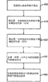
参考图3和图6,图3和图6示出用于确定气泡在流体管路中的流动速率的方法。在步骤400,允许流体在流体管路160中流动。在步骤410,确定在第一电容器110处的电容低于阈值的第一时间。在步骤420,确定在第二电容器120处的电容低于阈值的第二时间。通过检测电容器处的电容、比较在电容器处检测到的电容与参考电容,并且如果在电容器处检测到的电容低于参考电容,记录该检测到的电容值,并且将检测到的电容值关联于发生的时间,从而确定电容低于阈值的时间。在一个实施例中,比较器180进行电容比较。在一个实施例中,检测到的电容值储存在存储器175中。在一个实施例中,发生的时间由时钟195提供。Reference is made to FIGS. 3 and 6 , which illustrate a method for determining the flow rate of air bubbles in a fluid line. At
在步骤430,从第一时间减去第二时间或可替换地从第二时间减去第一时间,以得到气泡移动时间。在步骤440电容监控距离除以气泡移动时间以得到气泡流动速率。电容监控距离除以气泡移动时间可以由除法器190进行。气泡流动速率提供关于气体是否在管路中与流体以相同的速率流动的信息。正如上面所提到的,这个信息是有用的,因为可以确定气泡体积的精确指示,从而最小化产生的虚假或令人厌烦的报警的数目。At step 430, the second time is subtracted from the first time or alternatively the first time is subtracted from the second time to obtain the bubble travel time. In
此外,如果检测到认为有问题的气泡尺寸,即超过希望的气泡尺寸,则可以清除流体管路160。可替换地,如果气泡流动速率不是希望的,即太慢或太快,则可以清除流体管路160。对流体管路160的内含物的这种清除或排空确保病人不接收携带危险气泡的流体。Additionally,
前面公开实施例的描述使本领域的任何技术人员能够实践或利用本发明。对于本领域的技术人员而言这些实施例的各种修改将是很显然的,并且这里定义的一般原则可以应用于不脱离本发明的精神实质和范围的其他实施例。例如,任何合适的比较器可以用于比较检测到的电容和参考电容。类似的,任何合适的减法器可以用于确定差分电容。因此,本发明不想限制于这里所示的实施例,而是意图符合与这里公开的原则和新颖特征相一致的最宽范围。The foregoing description of the disclosed embodiments is provided to enable any person skilled in the art to make or use the invention. Various modifications to these embodiments will be readily apparent to those skilled in the art, and the generic principles defined herein may be applied to other embodiments without departing from the spirit and scope of the invention. For example, any suitable comparator may be used to compare the sensed capacitance to a reference capacitance. Similarly, any suitable subtractor may be used to determine the differential capacitance. Thus, the present invention is not intended to be limited to the embodiments shown herein but is to be accorded the widest scope consistent with the principles and novel features disclosed herein.
Claims (25)
Applications Claiming Priority (3)
| Application Number | Priority Date | Filing Date | Title |
|---|---|---|---|
| US12/142,321 | 2008-06-19 | ||
| US12/142,321 US8489341B2 (en) | 2008-06-19 | 2008-06-19 | Method and apparatus for volumetric gas in-line sensing |
| PCT/US2009/047820 WO2009155435A1 (en) | 2008-06-19 | 2009-06-18 | Method and apparatus for volumetric gas in-line sensing |
Publications (1)
| Publication Number | Publication Date |
|---|---|
| CN102066882A true CN102066882A (en) | 2011-05-18 |
Family
ID=40940565
Family Applications (1)
| Application Number | Title | Priority Date | Filing Date |
|---|---|---|---|
| CN2009801227927A Pending CN102066882A (en) | 2008-06-19 | 2009-06-18 | Method and device for detecting the volume of gas in a pipeline |
Country Status (12)
| Country | Link |
|---|---|
| US (1) | US8489341B2 (en) |
| EP (1) | EP2291620A1 (en) |
| JP (1) | JP2011525244A (en) |
| KR (1) | KR20110017457A (en) |
| CN (1) | CN102066882A (en) |
| AU (1) | AU2009260002A1 (en) |
| BR (1) | BRPI0915429A2 (en) |
| CA (1) | CA2727191A1 (en) |
| MX (1) | MX2010014007A (en) |
| RU (1) | RU2011101740A (en) |
| WO (1) | WO2009155435A1 (en) |
| ZA (1) | ZA201009048B (en) |
Cited By (5)
| Publication number | Priority date | Publication date | Assignee | Title |
|---|---|---|---|---|
| CN105920703A (en) * | 2016-05-19 | 2016-09-07 | 王卫东 | Infusion flow rate monitoring instrument |
| CN111135387A (en) * | 2020-02-27 | 2020-05-12 | 徐勇 | Dripping speed monitoring device and method based on multi-sensor fusion |
| CN113908383A (en) * | 2021-12-14 | 2022-01-11 | 极限人工智能有限公司 | Bubble detection method and device and triple tee system |
| CN115397488A (en) * | 2020-02-12 | 2022-11-25 | 康尔福盛303公司 | Multipurpose capacitive sensor for fluid pump |
| CN116370748A (en) * | 2011-12-21 | 2023-07-04 | 德卡产品有限公司 | device for controlling fluid flow |
Families Citing this family (13)
| Publication number | Priority date | Publication date | Assignee | Title |
|---|---|---|---|---|
| JP5493985B2 (en) * | 2010-02-23 | 2014-05-14 | セイコーエプソン株式会社 | Liquid transport device |
| US20120098668A1 (en) * | 2010-10-22 | 2012-04-26 | Peng Chen | Infusion monitoring alarm and method for monitoring and alarming for intravenous infusion |
| US10823164B2 (en) * | 2011-08-25 | 2020-11-03 | Ecolab Usa Inc. | Diaphragm pump for dosing a fluid capable of automatic degassing and an according method |
| EP2913641B1 (en) * | 2014-02-28 | 2019-07-31 | Yokogawa Electric Corporation | Multiphase flowmeter |
| DE102014214026A1 (en) | 2014-07-18 | 2016-01-21 | Fraunhofer-Gesellschaft zur Förderung der angewandten Forschung e.V. | Sensor for detecting a liquid in a fluid channel |
| JP6502657B2 (en) * | 2014-12-02 | 2019-04-17 | シーエムシー技術開発 株式会社 | Method and apparatus for measuring particle size distribution of fine bubbles |
| US10589022B2 (en) | 2015-12-30 | 2020-03-17 | Baxter Corporation Englewood | Syringe plunger positioning apparatus and method |
| US10898640B2 (en) | 2018-07-11 | 2021-01-26 | Flex, Ltd. | Visual detection for IV pump tube calibration |
| US11504469B2 (en) | 2018-07-11 | 2022-11-22 | Flex Ltd. | Reed switch detection for IV pump tube calibration |
| US10905821B2 (en) * | 2018-07-11 | 2021-02-02 | Flex, Ltd. | Capacitor detection for IV pump tube calibration |
| JP7050212B2 (en) * | 2019-04-26 | 2022-04-07 | 株式会社日立ハイテク | Automatic analyzer |
| US11850344B2 (en) * | 2021-08-11 | 2023-12-26 | Mozarc Medical Us Llc | Gas bubble sensor |
| US12130162B2 (en) * | 2022-07-11 | 2024-10-29 | Strain Measurement Devices, Inc. | Optical bubble sensor |
Family Cites Families (16)
| Publication number | Priority date | Publication date | Assignee | Title |
|---|---|---|---|---|
| US4043178A (en) * | 1976-05-06 | 1977-08-23 | Petrolite Corporation | Hydrogen probe system |
| US4367736A (en) * | 1980-08-25 | 1983-01-11 | Baxter Travenol Laboratories, Inc. | System for detecting bubble formation in clear and opaque fluids |
| US4565500A (en) * | 1983-02-24 | 1986-01-21 | Stewart-Riess Laboratories, Inc. | Air bubble detecting and discriminating circuit arrangement and method |
| US4710757A (en) * | 1984-02-14 | 1987-12-01 | Haase Wayne C | Planter monitor system |
| DE3433148C2 (en) * | 1984-09-10 | 1987-01-22 | Endress U. Hauser Gmbh U. Co, 7867 Maulburg | Arrangement for detecting spatial inhomogeneities in a dielectric |
| GB8721858D0 (en) * | 1987-09-17 | 1987-10-21 | Schlumberger Ltd | Measurement apparatus |
| US4835456A (en) * | 1988-02-01 | 1989-05-30 | Quantum Dynamics Company, Inc. | Cryogenic density and mass-flow measurement system |
| DE4034471C1 (en) | 1990-10-30 | 1992-03-19 | Robert Bosch Gmbh, 7000 Stuttgart, De | |
| GB9109074D0 (en) | 1991-04-26 | 1991-06-12 | Shell Int Research | A method and apparatus for measuring the gas and the liquid flowrate and the watercut of multiphase mixtures of oil,water and gas flowing through a pipeline |
| US5394339A (en) * | 1992-03-30 | 1995-02-28 | Paul-Munroe Hydraulics Inc. | Apparatus for analyzing oil well production fluid |
| FR2710538B1 (en) * | 1993-09-30 | 1995-12-01 | Becton Dickinson Co | Method and device for detecting bubbles in an infusion line. |
| US5455565A (en) * | 1993-11-08 | 1995-10-03 | Ivac Corporation | Fluid monitor system and method using a resonator |
| US6915703B2 (en) * | 2000-03-03 | 2005-07-12 | Shell Oil Company | Capacitance meter |
| GB2390683B (en) | 2002-04-06 | 2005-07-06 | Process Tomography Ltd | Flow measurement |
| CA2567860C (en) * | 2004-05-28 | 2013-10-15 | Enginivity Llc | Flow control and gas detection and gas removal in an intravenous fluid delivery system |
| JP4229885B2 (en) * | 2004-08-18 | 2009-02-25 | 株式会社デンソー | Capacitive physical quantity detector |
-
2008
- 2008-06-19 US US12/142,321 patent/US8489341B2/en active Active
-
2009
- 2009-06-18 MX MX2010014007A patent/MX2010014007A/en not_active Application Discontinuation
- 2009-06-18 WO PCT/US2009/047820 patent/WO2009155435A1/en not_active Ceased
- 2009-06-18 JP JP2011514813A patent/JP2011525244A/en active Pending
- 2009-06-18 RU RU2011101740/28A patent/RU2011101740A/en not_active Application Discontinuation
- 2009-06-18 BR BRPI0915429A patent/BRPI0915429A2/en not_active Application Discontinuation
- 2009-06-18 AU AU2009260002A patent/AU2009260002A1/en not_active Abandoned
- 2009-06-18 CN CN2009801227927A patent/CN102066882A/en active Pending
- 2009-06-18 KR KR1020117001152A patent/KR20110017457A/en not_active Withdrawn
- 2009-06-18 CA CA2727191A patent/CA2727191A1/en not_active Abandoned
- 2009-06-18 EP EP09767744A patent/EP2291620A1/en not_active Withdrawn
-
2010
- 2010-12-15 ZA ZA2010/09048A patent/ZA201009048B/en unknown
Cited By (6)
| Publication number | Priority date | Publication date | Assignee | Title |
|---|---|---|---|---|
| CN116370748A (en) * | 2011-12-21 | 2023-07-04 | 德卡产品有限公司 | device for controlling fluid flow |
| CN105920703A (en) * | 2016-05-19 | 2016-09-07 | 王卫东 | Infusion flow rate monitoring instrument |
| CN105920703B (en) * | 2016-05-19 | 2022-06-03 | 中国人民解放军总医院 | Infusion flow monitor |
| CN115397488A (en) * | 2020-02-12 | 2022-11-25 | 康尔福盛303公司 | Multipurpose capacitive sensor for fluid pump |
| CN111135387A (en) * | 2020-02-27 | 2020-05-12 | 徐勇 | Dripping speed monitoring device and method based on multi-sensor fusion |
| CN113908383A (en) * | 2021-12-14 | 2022-01-11 | 极限人工智能有限公司 | Bubble detection method and device and triple tee system |
Also Published As
| Publication number | Publication date |
|---|---|
| MX2010014007A (en) | 2011-05-23 |
| BRPI0915429A2 (en) | 2015-11-03 |
| US8489341B2 (en) | 2013-07-16 |
| ZA201009048B (en) | 2013-05-29 |
| CA2727191A1 (en) | 2009-12-23 |
| JP2011525244A (en) | 2011-09-15 |
| AU2009260002A1 (en) | 2009-12-23 |
| KR20110017457A (en) | 2011-02-21 |
| US20090319204A1 (en) | 2009-12-24 |
| WO2009155435A1 (en) | 2009-12-23 |
| RU2011101740A (en) | 2012-07-27 |
| EP2291620A1 (en) | 2011-03-09 |
Similar Documents
| Publication | Publication Date | Title |
|---|---|---|
| CN102066882A (en) | Method and device for detecting the volume of gas in a pipeline | |
| US8479573B2 (en) | Fluid level sensor | |
| CN108534866B (en) | A high-sensitivity and high-precision electronic liquid level sensor capable of remotely monitoring liquid level | |
| KR102073115B1 (en) | Magnetic pressure sensing system for infusion pump | |
| TW506842B (en) | Occlusion detection method and system for ambulatory drug infusion pump | |
| JP5757798B2 (en) | Non-invasive capacitive fill level measuring device and method for filling medium in a container | |
| EP2329232B1 (en) | Pneumatic tilt sensor for use with respiratory flow sensing device | |
| US10422680B2 (en) | Method for monitoring at least one media-specific property of a medium | |
| CA2897948A1 (en) | Urine monitoring systems and methods | |
| EP2880644A2 (en) | Smoke detection using change in permittivity of capacitor air dielectric | |
| TW201721105A (en) | Liquid level sensing device | |
| US12311157B2 (en) | Medical device with a thermal mass flow sensor for bubble detection | |
| WO2014193936A1 (en) | Hydrogen sulfide gas detector with humidity and temperature compensation | |
| WO2012035291A3 (en) | Leakage sensor | |
| CN105920703B (en) | Infusion flow monitor | |
| JPH0628681Y2 (en) | Abnormality detection device for particle detection device | |
| MX2022014769A (en) | Detection of change in the physico-chemical composition of a liquid. | |
| Ahmad et al. | Design and Implementation of Capacitive Drip Rate Monitoring Sensor for Intravenous (IV) Administration. | |
| WO2017116963A1 (en) | Capacitive single plate bubble detector | |
| CN110836859A (en) | Blood sample detection flow channel structure | |
| IT202100017630A1 (en) | Detection device for monitoring the amount of a liquid in a container. | |
| CZ2008398A3 (en) | Liquid level capacitance transducer |
Legal Events
| Date | Code | Title | Description |
|---|---|---|---|
| C06 | Publication | ||
| PB01 | Publication | ||
| C10 | Entry into substantive examination | ||
| SE01 | Entry into force of request for substantive examination | ||
| C02 | Deemed withdrawal of patent application after publication (patent law 2001) | ||
| WD01 | Invention patent application deemed withdrawn after publication |
Application publication date: 20110518 |