CN102064644A - Thin disc rotor type AC asynchronous motor - Google Patents
Thin disc rotor type AC asynchronous motor Download PDFInfo
- Publication number
- CN102064644A CN102064644A CN 201010503099 CN201010503099A CN102064644A CN 102064644 A CN102064644 A CN 102064644A CN 201010503099 CN201010503099 CN 201010503099 CN 201010503099 A CN201010503099 A CN 201010503099A CN 102064644 A CN102064644 A CN 102064644A
- Authority
- CN
- China
- Prior art keywords
- rear end
- end cap
- shell
- end cover
- rotating shaft
- Prior art date
- Legal status (The legal status is an assumption and is not a legal conclusion. Google has not performed a legal analysis and makes no representation as to the accuracy of the status listed.)
- Pending
Links
Images


Abstract
Description
技术领域technical field
本发明涉及交流异步电动机,特别是一种薄盘形转子式交流异步电动机。The invention relates to an AC asynchronous motor, in particular to a thin disk rotor type AC asynchronous motor.
背景技术Background technique
目前常见的采用薄盘形转子的电动机是印制绕组电动机,因为印制绕组电动机的薄盘形转子的转动惯量很小,反应迅速,运转平稳,并且轴向尺寸小,因此这种扁平式电机被广泛应用于空间尺寸狭窄的地方,但是由于印制绕组电动机的转子必须采用碳刷换向结构,所以使印制绕组电动机的结构非常复杂,同时碳刷换向结构使印制绕组电动机的使用寿命大为降低,因此,使这类电机在转动控制和使用环境上受到了比较大的限制。At present, the common motor with thin disk rotor is printed winding motor, because the moment of inertia of the thin disk rotor of the printed winding motor is small, the response is fast, the operation is stable, and the axial size is small, so this flat motor It is widely used in places with narrow space dimensions, but because the rotor of the printed winding motor must adopt a carbon brush commutation structure, the structure of the printed winding motor is very complicated, and the carbon brush commutation structure makes the use of the printed winding motor The service life is greatly reduced, therefore, this type of motor is subject to relatively large restrictions on rotation control and use environment.
发明内容Contents of the invention
本发明的目的就是为了克服现有印制绕组电动机所存在的缺点,提供了一种薄盘形转子式交流异步电动机。The object of the present invention is to provide a thin disk rotor type AC asynchronous motor in order to overcome the shortcomings of the existing printed winding motor.
本发明所采用的技术方案是:薄盘形转子式交流异步电动机包括转轴、前端盖、机座壳、后端盖、编码器、电磁线圈、薄盘形转子;前端盖由圆形或正多边形的前端盖壳和设在前端盖壳内侧的电磁极组成,在前端盖上朝向薄盘形转子的一侧设有放置前电磁线圈的空腔,空腔内均匀分布有用于固定前电磁线圈的与前端盖壳生成一体的导磁的电磁极,电磁极的个数为四个或四个以上。后端盖和前端盖的外部形状和尺寸相同,后端盖由圆形或正多边形的后端盖壳和设在后端盖壳内侧的电磁极组成,在后端盖上朝向薄盘形转子的一侧设有放置后电磁线圈的空腔,空腔内均匀分布有用于固定后电磁线圈的与后端盖壳生成一体的导磁的电磁极,电磁极的个数为四个或四个以上。在前端盖和后端盖的中心朝向薄盘形转子的一侧设有用于固定轴承的轴承座,在前端盖和后端盖上均匀分布有数个螺纹孔,通过这些螺纹孔,前端盖和后端盖用长螺钉固定在机座壳上。薄盘形转子的形状是薄圆盘形的,由金属制成;薄盘形转子的壁厚在0.01~5mm之间,薄盘形转子的中心位置设有一个开有中心孔的轴套,轴套的中心孔紧固地套在转轴上,转轴上在薄盘形转子的两侧分别装有两个轴承,两个轴承的外圈固定在前端盖和后端盖的轴承座内,前端盖和后端盖的中心位置都开有中心孔,转轴的输出端从前端盖的中心孔中伸出,转轴的另一端从后端盖的中心孔中伸出,从后端盖的中心孔中伸出的转轴的轴端开有螺纹孔和定位槽,编码器由编码器壳和用于测转速或测转角的编码盘组成,将编码盘用螺钉通过螺纹孔固定在转轴的定位槽上,编码器外壳用螺钉固定在后端盖上把编码盘保护在编码器壳内。The technical scheme adopted in the present invention is: the thin disk rotor type AC asynchronous motor includes a rotating shaft, a front end cover, a base shell, a rear end cover, an encoder, an electromagnetic coil, and a thin disk rotor; The front-end cover shell and the electromagnetic pole arranged inside the front-end cover shell are composed of a cavity for placing the front electromagnetic coil on the side of the front-end cover facing the thin disk-shaped rotor, and the holes for fixing the front electromagnetic coil are evenly distributed in the cavity. The magnetically conductive electromagnetic poles formed integrally with the front end cover shell, the number of electromagnetic poles is four or more. The outer shape and size of the rear end cover and the front end cover are the same. The rear end cover is composed of a circular or regular polygonal rear end cover shell and an electromagnetic pole arranged inside the rear end cover shell, facing the thin disc rotor on the rear end cover. There is a cavity for placing the rear electromagnetic coil on one side of the cavity, and the magnetically conductive electromagnetic poles used to fix the rear electromagnetic coil and the rear end cover shell are evenly distributed in the cavity, and the number of electromagnetic poles is four or four above. On the side of the center of the front end cover and the rear end cover facing the thin disk rotor, there is a bearing seat for fixing the bearing. Several threaded holes are evenly distributed on the front end cover and the rear end cover. Through these threaded holes, the front end cover and the rear end cover The end cover is fixed on the base shell with long screws. The shape of the thin disk rotor is a thin disk, made of metal; the wall thickness of the thin disk rotor is between 0.01 and 5mm, and the center of the thin disk rotor is provided with a bushing with a central hole. The center hole of the shaft sleeve is tightly set on the rotating shaft, and two bearings are respectively installed on both sides of the thin disk rotor on the rotating shaft. The outer rings of the two bearings are fixed in the bearing seats of the front end cover and the rear end cover. There is a central hole in the center of the cover and the rear end cover, the output end of the rotating shaft protrudes from the central hole of the front end cover, the other end of the rotating shaft protrudes from the central hole of the rear end cover, and the output end of the rotating shaft protrudes from the central hole of the rear end cover. There are threaded holes and positioning slots on the shaft end of the rotating shaft protruding from the center. The encoder is composed of an encoder housing and an encoding disc for measuring the rotational speed or rotation angle. The encoding disc is fixed on the positioning slot of the rotating shaft through the threaded hole with screws. , The encoder shell is fixed on the rear end cover with screws to protect the encoder disc in the encoder shell.
工作前,先并接(或串接)前端盖上两两相对的两个前电磁线圈和在后端盖上在相同位置上的两两相对的两个后电磁线圈作为工作磁极,使这四个电磁极产生的电磁场通过前端盖和后端盖的导磁作用形成一个闭环的磁场流,再并接(或串接)前端盖上另外两个前电磁线圈和在后端盖上在相同位置上的另外两个后电磁线圈作为控制磁极,使这四个电磁极产生的电磁场通过前端盖和后端盖的导磁作用形成一个闭环的磁场流,这两个闭环的磁场流以转轴的轴线为中心线相互垂直;工作时,在工作磁极和控制磁极上分别加上幅值相等、相位差90°电角度的对称电压,则在电机的气隙中产生环形的旋转磁场,旋转磁场在薄盘形转子中产生感应电流,电流在磁场中受力从而使薄盘形转子旋转,若改变控制极的电压幅值或相位电角度,则产生的磁场将是一个椭圆形旋转磁场,所以改变控制信号,就可以改变磁场的椭圆度,从而控制电机的转速,当没有控制电压或相位电角度为零时,薄盘形转子只受到脉动磁场的作用,薄盘形转子静止不动,当控制电压的相位相反时,薄盘形转子将反转。Before work, connect (or connect in series) the two opposite front electromagnetic coils on the front end cover and the two opposite rear electromagnetic coils on the same position on the rear end cover as the working magnetic poles, so that the four The electromagnetic field generated by each electromagnetic pole forms a closed-loop magnetic field flow through the magnetic conduction of the front end cover and the rear end cover, and then parallel (or serial connection) the other two front electromagnetic coils on the front end cover and the same position on the rear end cover The other two rear electromagnetic coils are used as control magnetic poles, so that the electromagnetic field generated by these four electromagnetic poles forms a closed-loop magnetic field flow through the magnetic conduction of the front end cover and the rear end cover. The two closed-loop magnetic field flows follow the axis of the shaft The center lines are perpendicular to each other; when working, a symmetrical voltage with equal amplitude and a phase difference of 90° electrical angle is applied to the working magnetic pole and the control magnetic pole respectively, then a circular rotating magnetic field is generated in the air gap of the motor, and the rotating magnetic field is thin The induced current is generated in the disk rotor, and the current is forced in the magnetic field to make the thin disk rotor rotate. If the voltage amplitude or phase electrical angle of the control pole is changed, the generated magnetic field will be an elliptical rotating magnetic field, so changing the control signal, the ellipticity of the magnetic field can be changed to control the speed of the motor. When there is no control voltage or the phase electrical angle is zero, the thin disc rotor is only affected by the pulsating magnetic field, and the thin disc rotor is stationary. When the control voltage The thin disc rotor will reverse direction when the phase of the rotor is reversed.
本发明采用导电性良好的薄的金属圆盘作为转子,在转子的两侧加装励磁绕组,使电机无刷化,电机在保持原有转矩特性接近于线性、转动惯量小、反应迅速、运转平稳等性能的同时,大大的提高了电机使用寿命,简化了电机结构,提高了电机的控制性能,拓宽了应用范围。The invention adopts a thin metal disc with good conductivity as the rotor, and installs excitation windings on both sides of the rotor to make the motor brushless. The motor maintains the original torque characteristic close to linear, the moment of inertia is small, and the response is fast. While running smoothly and other performances, the service life of the motor is greatly improved, the structure of the motor is simplified, the control performance of the motor is improved, and the application range is broadened.
附图说明Description of drawings
图1为本发明实施例交流异步电动机的外部结构示意图。Fig. 1 is a schematic diagram of the external structure of an AC asynchronous motor according to an embodiment of the present invention.
图2为本发明实施例交流异步电动机的结构剖示图。Fig. 2 is a structural sectional view of an AC asynchronous motor according to an embodiment of the present invention.
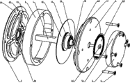
图3为本发明实施例交流异步电动机的结构分解示意图。Fig. 3 is an exploded schematic view of the structure of an AC asynchronous motor according to an embodiment of the present invention.
图4为本发明实施例交流异步电动机的前端盖或后端盖的分解示意图。Fig. 4 is an exploded schematic diagram of a front end cover or a rear end cover of an AC asynchronous motor according to an embodiment of the present invention.
图5为本发明实施例交流异步电动机的薄盘形转子的结构示意图。Fig. 5 is a schematic structural view of a thin disk rotor of an AC asynchronous motor according to an embodiment of the present invention.
图中标记:1.转轴,1-1.轴套,1-2.薄盘形转子,1-3.螺纹孔,1-4.定位槽,2.前端盖,2-1.前端盖壳,2-2.前电磁线圈,2-3.电磁极,2-4.前轴承,3.机座壳,4.后端盖,4-1.后端盖壳,4-2.后电磁线圈,4-4.后轴承,5.编码器,5-1.编码器壳,5-2.编码盘,5-3.螺钉,6.长螺钉。Marks in the figure: 1. Shaft, 1-1. Shaft sleeve, 1-2. Thin disc rotor, 1-3. Threaded hole, 1-4. Positioning groove, 2. Front end cover, 2-1. Front end cover shell , 2-2. Front electromagnetic coil, 2-3. Electromagnetic pole, 2-4. Front bearing, 3. Base shell, 4. Rear end cover, 4-1. Rear end cover shell, 4-2. Rear electromagnetic Coil, 4-4. Rear bearing, 5. Encoder, 5-1. Encoder shell, 5-2. Encoder disk, 5-3. Screw, 6. Long screw.
具体实施方式Detailed ways
实施例:Example:
如图1、图2、图3中所示,薄盘形转子式交流异步电动机包括转轴1、前端盖2、前电磁线圈2-2、机座壳3、后端盖4、后电磁线圈4-2、编码器5、薄盘形转子1-2;前端盖2由圆形的前端盖壳2-1和设在前端盖壳2-1内侧的电磁极2-3组成,在前端盖2上朝向薄盘形转子1-2的一侧设有放置前电磁线圈2-2的空腔,空腔内均匀分布有用于固定前电磁线圈2-2的与前端盖壳2-1生成一体的导磁的电磁极2-3,电磁极2-3的个数为四个。后端盖4和前端盖2的外部形状和尺寸相同,后端盖4由圆形的后端盖壳4-1和设在后端盖壳4-1内侧的电磁极2-3组成,在后端盖上朝向薄盘形转子1-2的一侧设有放置后电磁线圈4-2的空腔,空腔内均匀分布有用于固定后电磁线圈4-2的与后端盖壳4-1生成一体的导磁的电磁极2-3,电磁极2-3的个数为四个。在前端盖2和后端盖4的中心朝向薄盘形转子1-2的一侧设有用于固定前轴承2-4和后轴承4-4的轴承座,在前端盖2和后端盖4上均匀分布有4个螺纹孔,通过这些螺纹孔,前端盖2和后端盖4用长螺钉6固定在机座壳3上。薄盘形转子1-2的形状是薄圆盘形的,由金属制成;薄盘形转子1-2的壁厚为0.5mm,薄盘形转子1-2的中心位置设有一个开有中心孔的轴套1-1,轴套1-1的中心孔紧固的套在转轴1上,转轴1上在薄盘形转子1-2的两侧分别装有前轴承2-4和后轴承4-4,前轴承2-4和后轴承4-4的外圈固定在前端盖2和后端盖4的轴承座内,前端盖2和后端盖4的中心位置都开有中心孔,转轴1的输出端从前端盖2的中心孔中伸出,转轴1的另一端从后端盖4的中心孔中伸出,从后端盖4的中心孔中伸出的转轴1的轴端开有螺纹孔1-3和定位槽1-4,编码器5由编码器壳5-1和用于测转速或测转角的编码盘5-2组成,将编码盘5-2用螺钉5-3通过螺纹孔1-3固定在转轴1的定位槽1-4上,编码器外壳5-1用长螺钉6固定在后端盖4上把编码盘5-2保护在编码器壳5-1内。As shown in Fig. 1, Fig. 2 and Fig. 3, the thin disk rotor type AC asynchronous motor includes a rotating shaft 1, a front cover 2, a front electromagnetic coil 2-2, a
工作前,先并接前端盖2上两两相对的两个前电磁线圈2-2和在后端盖4上在相同位置上的两两相对的两个后电磁线圈4-2作为工作磁极,使这四个电磁极产生的电磁场通过前端盖2和后端盖4的导磁作用形成一个闭环的磁场流,再并接前端盖2上另外两个前电磁线圈2-2和在后端盖4上在相同位置上的另外两个后电磁线圈4-2作为控制磁极,使这四个电磁极产生的电磁场通过前端盖2和后端盖4的导磁作用形成一个闭环的磁场流,这两个闭环的磁场流以转轴1的轴线为中心线相互垂直;工作时,在工作磁极和控制磁极上分别加上幅值相等、相位差90°电角度的对称交流电,则在电机的气隙中产生环形的旋转磁场,旋转磁场在薄盘形转子1-2中产生感应电流,电流在磁场中受力从而使薄盘形转子1-2旋转,若改变控制极的电压幅值或相位电角度,则产生的磁场将是一个椭圆形旋转磁场,所以改变控制信号,就可以改变磁场的椭圆度,从而控制电机的转速,当没有控制电压或相位电角度为零时,薄盘形转子1-2只受到脉动磁场的作用,薄盘形转子1-2静止不动,当控制电压的相位相反时,薄盘形转子1-2将反转。Before work, connect two opposite front electromagnetic coils 2-2 on the front end cover 2 and two opposite rear electromagnetic coils 4-2 on the same position on the rear end cover 4 as working magnetic poles. Make the electromagnetic field produced by these four electromagnetic poles form a closed-loop magnetic field flow through the magnetic conduction effect of the front end cover 2 and the rear end cover 4, and then connect the other two front electromagnetic coils 2-2 on the front end cover 2 and the rear end cover 4, the other two rear electromagnetic coils 4-2 at the same position are used as control magnetic poles, so that the electromagnetic field generated by these four electromagnetic poles forms a closed-loop magnetic field flow through the magnetic conduction of the front end cover 2 and the rear end cover 4, which The two closed-loop magnetic field flows are perpendicular to each other with the axis of the rotating shaft 1 as the center line; when working, a symmetrical alternating current with equal amplitude and a phase difference of 90° electrical angle is added to the working magnetic pole and the control magnetic pole respectively, and the air gap of the motor A ring-shaped rotating magnetic field is generated in the center, and the rotating magnetic field generates an induced current in the thin disc rotor 1-2, and the current is forced in the magnetic field to make the thin disc rotor 1-2 rotate. If the voltage amplitude or phase voltage of the control pole is changed Angle, the generated magnetic field will be an elliptical rotating magnetic field, so changing the control signal can change the ellipticity of the magnetic field, thereby controlling the speed of the motor. When there is no control voltage or the phase electrical angle is zero, the thin disc rotor 1 -2 is only affected by the pulsating magnetic field, the thin disc rotor 1-2 is stationary, and when the phase of the control voltage is opposite, the thin disc rotor 1-2 will reverse.
Claims (1)
Priority Applications (1)
| Application Number | Priority Date | Filing Date | Title |
|---|---|---|---|
| CN 201010503099 CN102064644A (en) | 2010-10-10 | 2010-10-10 | Thin disc rotor type AC asynchronous motor |
Applications Claiming Priority (1)
| Application Number | Priority Date | Filing Date | Title |
|---|---|---|---|
| CN 201010503099 CN102064644A (en) | 2010-10-10 | 2010-10-10 | Thin disc rotor type AC asynchronous motor |
Publications (1)
| Publication Number | Publication Date |
|---|---|
| CN102064644A true CN102064644A (en) | 2011-05-18 |
Family
ID=43999799
Family Applications (1)
| Application Number | Title | Priority Date | Filing Date |
|---|---|---|---|
| CN 201010503099 Pending CN102064644A (en) | 2010-10-10 | 2010-10-10 | Thin disc rotor type AC asynchronous motor |
Country Status (1)
| Country | Link |
|---|---|
| CN (1) | CN102064644A (en) |
Cited By (2)
| Publication number | Priority date | Publication date | Assignee | Title |
|---|---|---|---|---|
| CN104359684A (en) * | 2014-12-11 | 2015-02-18 | 重庆和平自动化工程股份有限公司 | Loader structure of engine online testing platform |
| CN112230143A (en) * | 2020-09-27 | 2021-01-15 | 中车永济电机有限公司 | Asynchronous motor online detection device and method |
Citations (8)
| Publication number | Priority date | Publication date | Assignee | Title |
|---|---|---|---|---|
| CN2488222Y (en) * | 2001-06-27 | 2002-04-24 | 季鹏凯 | Vertical disk electric machine |
| CN1901327A (en) * | 2005-07-21 | 2007-01-24 | 日产自动车株式会社 | Electric generator |
| CN1956294A (en) * | 2005-10-28 | 2007-05-02 | 浙江大学 | Permanent Disk Surface Motor |
| CN2912093Y (en) * | 2006-03-21 | 2007-06-13 | 何志成 | Assembling permanent-magnet d.c.dynamo |
| CN201107842Y (en) * | 2006-12-04 | 2008-08-27 | 袁会文 | Disc type switch reluctance motor |
| CN101282057A (en) * | 2008-03-27 | 2008-10-08 | 江苏凯宫机械股份有限公司 | Encoder structure of frequency conversion motor on roving machine |
| CN101299564A (en) * | 2008-03-14 | 2008-11-05 | 北京合康亿盛科技有限公司 | Device for joining motor main axle and encoder |
| CN201527275U (en) * | 2009-04-30 | 2010-07-14 | 郝双晖 | Position detection device and signal processing device thereof |
-
2010
- 2010-10-10 CN CN 201010503099 patent/CN102064644A/en active Pending
Patent Citations (8)
| Publication number | Priority date | Publication date | Assignee | Title |
|---|---|---|---|---|
| CN2488222Y (en) * | 2001-06-27 | 2002-04-24 | 季鹏凯 | Vertical disk electric machine |
| CN1901327A (en) * | 2005-07-21 | 2007-01-24 | 日产自动车株式会社 | Electric generator |
| CN1956294A (en) * | 2005-10-28 | 2007-05-02 | 浙江大学 | Permanent Disk Surface Motor |
| CN2912093Y (en) * | 2006-03-21 | 2007-06-13 | 何志成 | Assembling permanent-magnet d.c.dynamo |
| CN201107842Y (en) * | 2006-12-04 | 2008-08-27 | 袁会文 | Disc type switch reluctance motor |
| CN101299564A (en) * | 2008-03-14 | 2008-11-05 | 北京合康亿盛科技有限公司 | Device for joining motor main axle and encoder |
| CN101282057A (en) * | 2008-03-27 | 2008-10-08 | 江苏凯宫机械股份有限公司 | Encoder structure of frequency conversion motor on roving machine |
| CN201527275U (en) * | 2009-04-30 | 2010-07-14 | 郝双晖 | Position detection device and signal processing device thereof |
Cited By (2)
| Publication number | Priority date | Publication date | Assignee | Title |
|---|---|---|---|---|
| CN104359684A (en) * | 2014-12-11 | 2015-02-18 | 重庆和平自动化工程股份有限公司 | Loader structure of engine online testing platform |
| CN112230143A (en) * | 2020-09-27 | 2021-01-15 | 中车永济电机有限公司 | Asynchronous motor online detection device and method |
Similar Documents
| Publication | Publication Date | Title |
|---|---|---|
| JP6068644B2 (en) | Permanent magnetic laminated motor | |
| US7230359B2 (en) | Electric motor with poles shaped to minimize cogging torque | |
| JP5292530B2 (en) | Brushless motor | |
| WO2015051740A1 (en) | Disc power generator | |
| CN110518724B (en) | Stator permanent magnet type bearingless sheet motor and working method thereof | |
| US20190242389A1 (en) | Inner-rotor fan | |
| CN103986301B (en) | High-dynamic moving-magnetic type linear rotation integrated two-degree-of-freedom motor | |
| CN105471212B (en) | A kind of rotational alignment magneto | |
| JP2015092810A (en) | Brushless motor and blower using motor | |
| CN110581614B (en) | Servo limited angle torque motor | |
| CN106787302B (en) | A bearingless permanent magnet sheet motor | |
| CN107591979A (en) | Rotor axial magnetizes permanent magnet switched reluctance motor | |
| CN102064644A (en) | Thin disc rotor type AC asynchronous motor | |
| CN201821239U (en) | An AC asynchronous motor | |
| JPH01318536A (en) | Brushless dc motor and rotor magnet therefor | |
| CN106921227A (en) | A kind of absence of commutator permanent magnet DC motor | |
| CN102723841B (en) | Flat stepping motor | |
| CN103095055B (en) | Brush motor and use the fan of this brush motor | |
| CN115441682A (en) | Stator permanent magnet type bearingless sheet motor | |
| TWM347747U (en) | Permanent-magnetism type motor rotator | |
| JP6050102B2 (en) | Brushless motor and blower | |
| CN222052718U (en) | An electromagnetic induction structure | |
| CN202652037U (en) | Flat Stepper Motor | |
| JP5313627B2 (en) | Brush-fed hybrid excitation motor and driving method of brush-fed hybrid excitation motor | |
| JP2012060709A (en) | Permanent magnet motor |
Legal Events
| Date | Code | Title | Description |
|---|---|---|---|
| C06 | Publication | ||
| PB01 | Publication | ||
| C10 | Entry into substantive examination | ||
| SE01 | Entry into force of request for substantive examination | ||
| C02 | Deemed withdrawal of patent application after publication (patent law 2001) | ||
| WD01 | Invention patent application deemed withdrawn after publication |
Application publication date: 20110518 |