CN102014732B - Ophthalmologic apparatus for the observation, examination, diagnosis, and/or treatment of an eye - Google Patents
Ophthalmologic apparatus for the observation, examination, diagnosis, and/or treatment of an eye Download PDFInfo
- Publication number
- CN102014732B CN102014732B CN200980115171.6A CN200980115171A CN102014732B CN 102014732 B CN102014732 B CN 102014732B CN 200980115171 A CN200980115171 A CN 200980115171A CN 102014732 B CN102014732 B CN 102014732B
- Authority
- CN
- China
- Prior art keywords
- eye
- scanning
- laser
- light
- eyes
- Prior art date
- Legal status (The legal status is an assumption and is not a legal conclusion. Google has not performed a legal analysis and makes no representation as to the accuracy of the status listed.)
- Expired - Fee Related
Links
Images


Classifications
-
- A—HUMAN NECESSITIES
- A61—MEDICAL OR VETERINARY SCIENCE; HYGIENE
- A61B—DIAGNOSIS; SURGERY; IDENTIFICATION
- A61B3/00—Apparatus for testing the eyes; Instruments for examining the eyes
- A61B3/10—Objective types, i.e. instruments for examining the eyes independent of the patients' perceptions or reactions
- A61B3/1025—Objective types, i.e. instruments for examining the eyes independent of the patients' perceptions or reactions for confocal scanning
-
- A—HUMAN NECESSITIES
- A61—MEDICAL OR VETERINARY SCIENCE; HYGIENE
- A61F—FILTERS IMPLANTABLE INTO BLOOD VESSELS; PROSTHESES; DEVICES PROVIDING PATENCY TO, OR PREVENTING COLLAPSING OF, TUBULAR STRUCTURES OF THE BODY, e.g. STENTS; ORTHOPAEDIC, NURSING OR CONTRACEPTIVE DEVICES; FOMENTATION; TREATMENT OR PROTECTION OF EYES OR EARS; BANDAGES, DRESSINGS OR ABSORBENT PADS; FIRST-AID KITS
- A61F9/00—Methods or devices for treatment of the eyes; Devices for putting in contact-lenses; Devices to correct squinting; Apparatus to guide the blind; Protective devices for the eyes, carried on the body or in the hand
- A61F9/007—Methods or devices for eye surgery
- A61F9/008—Methods or devices for eye surgery using laser
- A61F9/00821—Methods or devices for eye surgery using laser for coagulation
-
- G—PHYSICS
- G01—MEASURING; TESTING
- G01B—MEASURING LENGTH, THICKNESS OR SIMILAR LINEAR DIMENSIONS; MEASURING ANGLES; MEASURING AREAS; MEASURING IRREGULARITIES OF SURFACES OR CONTOURS
- G01B9/00—Measuring instruments characterised by the use of optical techniques
- G01B9/02—Interferometers
- G01B9/0209—Low-coherence interferometers
- G01B9/02091—Tomographic interferometers, e.g. based on optical coherence
-
- A—HUMAN NECESSITIES
- A61—MEDICAL OR VETERINARY SCIENCE; HYGIENE
- A61F—FILTERS IMPLANTABLE INTO BLOOD VESSELS; PROSTHESES; DEVICES PROVIDING PATENCY TO, OR PREVENTING COLLAPSING OF, TUBULAR STRUCTURES OF THE BODY, e.g. STENTS; ORTHOPAEDIC, NURSING OR CONTRACEPTIVE DEVICES; FOMENTATION; TREATMENT OR PROTECTION OF EYES OR EARS; BANDAGES, DRESSINGS OR ABSORBENT PADS; FIRST-AID KITS
- A61F9/00—Methods or devices for treatment of the eyes; Devices for putting in contact-lenses; Devices to correct squinting; Apparatus to guide the blind; Protective devices for the eyes, carried on the body or in the hand
- A61F9/007—Methods or devices for eye surgery
- A61F9/008—Methods or devices for eye surgery using laser
- A61F2009/00844—Feedback systems
- A61F2009/00846—Eyetracking
-
- A—HUMAN NECESSITIES
- A61—MEDICAL OR VETERINARY SCIENCE; HYGIENE
- A61F—FILTERS IMPLANTABLE INTO BLOOD VESSELS; PROSTHESES; DEVICES PROVIDING PATENCY TO, OR PREVENTING COLLAPSING OF, TUBULAR STRUCTURES OF THE BODY, e.g. STENTS; ORTHOPAEDIC, NURSING OR CONTRACEPTIVE DEVICES; FOMENTATION; TREATMENT OR PROTECTION OF EYES OR EARS; BANDAGES, DRESSINGS OR ABSORBENT PADS; FIRST-AID KITS
- A61F9/00—Methods or devices for treatment of the eyes; Devices for putting in contact-lenses; Devices to correct squinting; Apparatus to guide the blind; Protective devices for the eyes, carried on the body or in the hand
- A61F9/007—Methods or devices for eye surgery
- A61F9/008—Methods or devices for eye surgery using laser
- A61F2009/00861—Methods or devices for eye surgery using laser adapted for treatment at a particular location
- A61F2009/00863—Retina
-
- A—HUMAN NECESSITIES
- A61—MEDICAL OR VETERINARY SCIENCE; HYGIENE
- A61F—FILTERS IMPLANTABLE INTO BLOOD VESSELS; PROSTHESES; DEVICES PROVIDING PATENCY TO, OR PREVENTING COLLAPSING OF, TUBULAR STRUCTURES OF THE BODY, e.g. STENTS; ORTHOPAEDIC, NURSING OR CONTRACEPTIVE DEVICES; FOMENTATION; TREATMENT OR PROTECTION OF EYES OR EARS; BANDAGES, DRESSINGS OR ABSORBENT PADS; FIRST-AID KITS
- A61F9/00—Methods or devices for treatment of the eyes; Devices for putting in contact-lenses; Devices to correct squinting; Apparatus to guide the blind; Protective devices for the eyes, carried on the body or in the hand
- A61F9/007—Methods or devices for eye surgery
- A61F9/008—Methods or devices for eye surgery using laser
- A61F2009/00897—Scanning mechanisms or algorithms
Landscapes
- Health & Medical Sciences (AREA)
- Life Sciences & Earth Sciences (AREA)
- Ophthalmology & Optometry (AREA)
- General Health & Medical Sciences (AREA)
- Physics & Mathematics (AREA)
- Animal Behavior & Ethology (AREA)
- Nuclear Medicine, Radiotherapy & Molecular Imaging (AREA)
- Veterinary Medicine (AREA)
- Public Health (AREA)
- Engineering & Computer Science (AREA)
- Biomedical Technology (AREA)
- Heart & Thoracic Surgery (AREA)
- Surgery (AREA)
- Optics & Photonics (AREA)
- Vascular Medicine (AREA)
- Molecular Biology (AREA)
- Medical Informatics (AREA)
- General Physics & Mathematics (AREA)
- Radiology & Medical Imaging (AREA)
- Biophysics (AREA)
- Eye Examination Apparatus (AREA)
Abstract
Description
技术领域 technical field
本发明涉及用于以无接触和无触碰的方式观察、检查、诊断和/或治疗眼睛的眼科设备和方法。该设备在其构造方面基于眼底相机或检眼镜。 The present invention relates to ophthalmic devices and methods for observing, examining, diagnosing and/or treating the eye in a contact-free and touch-free manner. The device is based on a fundus camera or ophthalmoscope in its construction. the
背景技术Background technique
眼底(视网膜或眼底)的局部解剖结构的成像是用于诊断许多眼部疾病的重要手段。视网膜上的许多疾病可以通过精确到点地(punktgenau)使用诊断激光来更准确地被检查或者通过精确到点地施加治疗激光来被诊疗。 Imaging of the topographical structure of the fundus (retina or fundus) is an important tool for diagnosing many ocular diseases. Many diseases of the retina can be examined more precisely by the precise application of a diagnostic laser or by the precise application of a therapeutic laser. the
为了观察、诊断和治疗眼睛,根据现有技术公知有大量不同的解决方案。为此所需的成像例如利用手持式检眼镜、狭缝灯、眼底相机或激光扫描检眼镜来产生。 For the observation, diagnosis and treatment of the eye, a large number of different solutions are known from the prior art. The images required for this are produced, for example, with hand-held ophthalmoscopes, slit lamps, fundus cameras or laser scanning ophthalmoscopes. the
在此,眼底相机是眼科学中最重要的诊断仪器之一。借助于眼底相机,可以拍摄眼底的宽视场图像(Weitfeldbild)并且由此得出诊断。 Here, the fundus camera is one of the most important diagnostic instruments in ophthalmology. With the aid of a fundus camera, wide-field images of the fundus can be recorded and a diagnosis can be derived therefrom. the
R.F.Spaide在[1]中描述有专门的实施例,利用所述实施例甚至可以除单纯评价RGB图像(红绿蓝)以外还使用功能性的诊断形式。 R.F. Spaide [1] describes specific examples with which it is even possible to use functional diagnostic forms in addition to the pure evaluation of RGB images (red-green-blue). the
因此,在US7,134,754B2中例如描述有一种视网膜功能相机,其使用两个具有不同波长的激光源。在此,波长带被选择为使得在富有氧的血液的情况下对第一波长带的光吸收能力以及在脱氧的血液的情况下对第二波长带的光吸收能力较大,从而可以产生和分析相应的图像。由此,早期的斑状萎缩就已经可以被诊断出,其中在斑状萎缩的情况下,与年龄有关地导致感光细胞和视网膜色素上皮细胞萎缩,并且导致分辨细节的中心视力的逐渐丧失。 Thus, in US Pat. No. 7,134,754 B2, for example, a retinal function camera is described which uses two laser light sources with different wavelengths. In this case, the wavelength bands are selected such that the light absorption of the first wavelength band in the case of oxygen-rich blood and the light absorption of the second wavelength band in the case of deoxygenated blood is greater, so that a and Analyze the corresponding images. As a result, early macular atrophy can already be diagnosed, in which age-related atrophy of the photoreceptor cells and retinal pigment epithelium results and a gradual loss of central vision for resolving fine details. the
但是利用所述解决方案,也可以在早期识别脉络膜新生血管的产生。这些小的异常新血管从脉络膜层中长出并增生,并且可能在血液在视网膜中或视网膜下聚集时引起急性视力丧失。利用所述解决方案被可视化的所识别的部位可以要么通过光凝、要么通过光力学疗法来诊疗。 With the described solution, however, the development of choroidal neovascularization can also be recognized at an early stage. These small abnormal new blood vessels grow and proliferate from the choroid layer and may cause acute vision loss when blood pools in or under the retina. The identified sites visualized with the solution can be treated either by photocoagulation or by photodynamic therapy. the
同样使用两个具有不同波长的激光源的眼底相机在US 7,198,367B2中予以了描述。但在此,波长带被选择为使得可以在可见光范围中以及在红外范围中拍摄和分析眼底的荧光图像。 A fundus camera also using two laser sources with different wavelengths is described in US 7,198,367 B2. Here, however, the wavelength band is selected such that fluorescence images of the fundus can be recorded and analyzed in the visible range as well as in the infrared range. the
此外,但是迄今为止关于眼底相机所公知的功能性诊断形式基于宽视场照射的原理。但是利用该系统不能对视网膜的各个点进行的复杂的诊断,例如视野测量、光学相干断层扫描或者通过凝结进行精确到点的治疗。 Furthermore, however, the previously known forms of functional diagnosis with fundus cameras are based on the principle of wide-field illumination. However, complex diagnostics at individual points of the retina, such as perimetry, optical coherence tomography or point-specific therapy by coagulation, cannot be carried out with this system. the
此外,在眼科学中同样已经设立了激光扫描检眼镜。在此,激光束大多共焦地通过机械扫描仪、例如检流计扫描仪或者多角镜被成像到视网膜上。由成像点处的视网膜所发回的光被位于设备中的传感器探测。关于视网膜的局部解剖结构的信息借助于扫描仪通过扫描被获得。在激光扫描检眼镜的情况下可以对视网膜执行精确到点的治疗或诊断。在常规激光扫描检眼镜的情况下,激光器充当既用于成像又用于诊断和/或治疗的光源。 Furthermore, laser scanning ophthalmoscopes have likewise been established in ophthalmology. In this case, the laser beam is usually imaged confocally onto the retina by means of a mechanical scanner, for example a galvanometer scanner or a polygon mirror. Light sent back by the retina at the imaging point is detected by a sensor located in the device. Information about the topographical structure of the retina is obtained by scanning with the aid of a scanner. In the case of a laser scanning ophthalmoscope, it is possible to perform a spot-precise treatment or diagnosis of the retina. In the case of conventional laser scanning ophthalmoscopes, the laser acts as a light source both for imaging and for diagnosis and/or treatment. the
但是由于在观察期间病人的眼睛可能相对于检眼镜运动,因此需要持续地观察眼底的局部解剖结构。出于该原因,在所有公知的激光扫描检眼镜中都使用以共振方式运行的持续地扫描视网膜的扫描仪。仅当扫描仪被恰好定向为使得激光点正好覆盖视网膜上的所期望的点时,才能执行精确到点的治疗或诊断。也就是需要对扫描仪与治疗或诊断激光器之间进行高成本的同步。 However, since the patient's eye may move relative to the ophthalmoscope during observation, it is necessary to continuously observe the topographic structure of the fundus. For this reason, a resonantly operating scanner that continuously scans the retina is used in all known laser scanning ophthalmoscopes. Spot-accurate treatment or diagnosis can only be performed if the scanner is properly oriented such that the laser spot covers exactly the desired spot on the retina. This means costly synchronization between the scanner and the therapeutic or diagnostic laser. the
为了在诊疗时不超过最大允许的脉冲能量,需要通过高成本的定位装置和强度监测装置根据扫描激光束的强度来监控扫描激光束的停留时间。在WO 2004/043234A1中例如描述有一种经过优化的激光扫描检眼镜,其中共焦的激光扫描激光检眼镜与外部的激光源相组合,以便能够同时观察和诊疗视网膜上的同一点。 In order not to exceed the maximum permissible pulse energy during diagnosis and treatment, the dwell time of the scanning laser beam needs to be monitored as a function of the intensity of the scanning laser beam by means of cost-intensive positioning and intensity monitoring devices. In WO 2004/043234 A1, for example, an optimized laser scanning ophthalmoscope is described, in which a confocal laser scanning laser ophthalmoscope is combined with an external laser source in order to simultaneously observe and treat the same spot on the retina. the
为此,EP 1308124A2描述有一种供与激光扫描检眼镜一起使用的物镜系统。所述物镜系统实现非常宽的宽视场,使得激光扫描检眼镜可以检查在通常情况下不能达到的眼睛区域。 To this end, EP 1308124A2 describes an objective lens system for use with a laser scanning ophthalmoscope. The objective system achieves a very wide field of view so that laser scanning ophthalmoscopes can examine areas of the eye that are normally inaccessible. the
在US 6,337,920B1中描述有另一种激光扫描检眼镜。由产生激光束的激光源、用于产生第一方向上的振荡射束偏转的第一扫描装置、以及用于产生第二方向上的振荡射束偏转的第二扫描装置构成的激光 扫描检眼镜(LSO)此外还具有用于检测由眼睛反射的光的探测装置。 Another laser scanning ophthalmoscope is described in US 6,337,920 B1. Laser scanning ophthalmoscope consisting of a laser source producing a laser beam, a first scanning device for producing a deflection of the oscillating beam in a first direction, and a second scanning device for producing a deflection of the oscillating beam in a second direction The (LSO) also has a detection device for detecting the light reflected by the eye. the
从通过首次扫描视网膜所产生的眼底图像中可以选择、尤其是可以细化第二次扫描所限于的眼底子区域。为此,各个扫描装置可以通过可以被控制单元控制的驱动电机彼此无关地被偏转。 From the fundus image produced by the first scan of the retina, subregions of the fundus to which the second scan is limited can be selected, in particular can be refined. For this purpose, the individual scanning devices can be pivoted independently of one another by drive motors which can be controlled by the control unit. the
DE 3836860C2描述有一种采用激光束扫描的眼科设备。在该解决方案中也使用两个波长。一个激光束被用于凝结/激发眼底,而另一激光束被用于对眼底进行扫描成像,其中两个激光束被彼此并行和同时地使用。利用该解决方案,提供了一种采用激光束扫描的检眼镜,利用所述检眼镜可以在屏幕上标出眼底的标记部位,并且产生该部位的令人满意的图像。 DE 3836860C2 describes an ophthalmic device that uses laser beam scanning. Also two wavelengths are used in this solution. One laser beam is used to coagulate/excite the fundus, and the other laser beam is used to scan and image the fundus, where the two laser beams are used in parallel and simultaneously with each other. With this solution, an ophthalmoscope scanning with a laser beam is provided, with which a marking site of the fundus can be marked on the screen and a satisfactory image of this site is produced. the
用于同时对眼底成像以及将治疗激光施加到视网膜上的第三种可能性在于使用狭缝灯。但是为了能够精确到点地定位狭缝灯,需要将眼睛固定。通常通过隐形眼镜来实现固定。此外,该隐形眼镜用于补偿眼的屈光度。 A third possibility for simultaneous imaging of the fundus and application of therapeutic laser light to the retina consists in the use of slit lamps. But in order to be able to precisely position the slit lamp, the eyes need to be fixed. Immobilization is usually achieved with contact lenses. In addition, the contact lens is used to compensate for the diopter of the eye. the
在此不利地造成利用狭缝灯的激光凝结需要隐形眼镜,并且其可再现性极小。 The disadvantage here is that laser coagulation with slit lamps requires contact lenses and has very little reproducibility. the
此外,激光斑在视网膜上的定位的精确度强烈取决于操作者,因为仅当扫描仪恰好被定向为使得激光点正好覆盖视网膜上的所期望的点时,才能执行精确到点的治疗或诊断。为此绝对需要在扫描仪与治疗或诊断激光器之间进行高成本的同步。为了在诊疗时不超过最大允许的脉冲能量,需要通过高成本的定位装置和强度监测装置根据扫描激光束的强度来监控扫描激光束在感兴趣点上的停留时间。 Furthermore, the accuracy of the positioning of the laser spot on the retina is strongly dependent on the operator, since spot-accurate treatment or diagnosis can only be performed if the scanner is oriented exactly so that the laser spot covers exactly the desired spot on the retina . A cost-intensive synchronization between the scanner and the therapeutic or diagnostic laser is absolutely necessary for this. In order not to exceed the maximum permissible pulse energy during diagnosis and treatment, it is necessary to monitor the dwell time of the scanning laser beam at the point of interest by means of cost-intensive positioning and intensity monitoring devices as a function of the intensity of the scanning laser beam. the
在WO 2007/035855A2中描述的方法以及相应的设备基于如下狭缝灯的原理:所述狭缝灯被扩展为具有扫描单元,以便对病人眼睛的视网膜执行图案支持的激光凝结。但是为此需要将隐形眼镜定位到病人眼睛上,利用所述隐形眼镜来补偿眼睛的屈光度或执行用于凝结的激光的射束成形。另外,由于与眼底相机相比非常小的观察范围,仅能对视网膜进行局部治疗。这是由于狭缝灯的原理性构造。为了治疗更大范围的视网膜,必须要么移动病人的眼睛,要么使用专门的隐形眼镜。 The method described in WO 2007/035855 A2 and the corresponding device are based on the principle of a slit lamp which is extended with a scanning unit in order to perform pattern-supported laser coagulation on the retina of a patient's eye. For this, however, it is necessary to position a contact lens on the patient's eye, with which the diopter of the eye is compensated or beam shaping of the laser light for coagulation is carried out. In addition, due to the very small field of view compared to the fundus camera, only partial treatment of the retina is possible. This is due to the principle construction of the slit lamp. To treat a larger area of the retina, the patient's eye must either be moved or specialized contact lenses used. the
此外,不能执行凝结激光器的基于眼底图像的定位以及记录所设置的凝结点。同样不可能的是譬如视野测量、荧光成像、光谱分析或者 光学相干断层扫描的诊断方法。 Furthermore, fundus image-based localization of the coagulation laser and recording of the set coagulation point cannot be performed. Also not possible are diagnostic methods such as perimetry, fluorescence imaging, spectral analysis or optical coherence tomography. the
文献: Literature:
[1]Spaide,R.F.,“Fundus autofluorescence and age-related macular degeneration”,Ophthalmology 110(2),2003年2月,第392-399页。 [1] Spaide, R.F., "Fundus autofluorescence and age-related macular degeneration", Ophthalmology 110(2), February 2003, pp. 392-399. the
发明内容 Contents of the invention
本发明所基于的任务是,开发用于以无接触和无触碰的方式观察、检查、诊断和/或治疗眼睛的眼科设备和方法。在此,将可以利用优选地在构造方面基于眼底相机或检眼镜的该设备与诊断和/或治疗无关地进行观察或图像获取。要开发的解决方案尤其是将实现高的可再现性以及从检查、经诊断到治疗过程的自动记录。 The object underlying the present invention is to develop an ophthalmic device and a method for observing, examining, diagnosing and/or treating the eye in a contact-free and contact-free manner. In this case, observation or image acquisition will be possible independently of diagnosis and/or therapy with the device, which is preferably constructed based on a fundus camera or an ophthalmoscope. The solution to be developed is to achieve, inter alia, a high reproducibility and an automatic documentation of the procedure from examination, diagnosis to treatment. the
根据本发明,该任务通过独立权利要求的特征来解决。优选的改进方案和扩展方案是从属权利要求的主题。 This object is solved according to the invention by the features of the independent claims. Preferred refinements and developments are the subject matter of the subclaims. the
根据本发明的用于观察、检查、诊断和/或治疗眼睛的眼科设备由下列项目构成:照射光路,其从第一照射源出发通向眼睛并且具有有孔镜(Lochspiegel)和成像光学元件;以及观察光路,其从眼睛出发通过成像光学元件并且穿过有孔镜通向探测器。该眼科设备附加地具有用于扫描照射的光路,该光路从第二照射源出发通向眼睛并且除了成像光学元件以外还具有扫描单元、物镜和分束器。在此,成像光学元件以及整个光路都被实施为使得它们没有内部反射。被布置在用于扫描照射的光路中的扫描单元被构造成一个以静电和/或电流测定方式被驱动的双向翻转镜(Kippspiegel)或者两个以静电和/或电流测定方式被驱动的单向翻转镜。在使用两个可以以静电和/或电流测定方式被驱动的单向翻转镜的情况下,优选地进行所述镜到彼此上的中间成像。 The ophthalmic device according to the invention for observing, examining, diagnosing and/or treating the eye consists of the following items: an illumination beam path, which leads from a first illumination source to the eye and has a perforated mirror (Lochspiegel) and imaging optics; And the observation beam path, which leads from the eye through the imaging optics and through the apertured mirror to the detector. The ophthalmic device additionally has a beam path for the scanning radiation, which leads from the second radiation source to the eye and, in addition to the imaging optics, also has a scanning unit, an objective lens and a beam splitter. Here, the imaging optics as well as the entire beam path are embodied in such a way that they are free of internal reflections. The scanning unit arranged in the beam path for the scanning illumination is configured as an electrostatically and/or amperometrically driven bidirectional flip mirror (Kipspiegel) or as two electrostatically and/or agalvanically driven unidirectional flip mirror. When using two one-way flip mirrors, which can be driven electrostatically and/or amperometrically, an intermediate imaging of the mirrors onto one another is preferably carried out. the
在根据本发明的用于观察、检查、诊断和/或治疗眼睛的眼科方法中,为了观察和检查而由第一照射源以及为了诊断和/或治疗由第二照射源彼此无关地照射眼睛。从眼睛发出的、既由第一照射源也由第二照射源所发起的光通过成像光学元件以及穿过有孔镜被成像到探测器上、被拍摄、处理、分析、记录和存储。 In the ophthalmic method according to the invention for observing, examining, diagnosing and/or treating the eye, the eye is irradiated independently of each other by the first radiation source for observation and examination and by the second radiation source for diagnosis and/or treatment. Light emanating from the eye, initiated by both the first and the second illumination source, is imaged onto the detector, imaged, processed, analyzed, recorded and stored through the imaging optics and through the apertured mirror. the
在常规的激光扫描检眼镜的情况下,激光器例如被用作既用于成像又用于诊断和/或治疗的光源。为此通过以共振方式运行的扫描仪(检流计扫描仪,多边形)利用激光扫描视网膜上的视场。与之不同,在由要求专利保护的解决方案中,通过宽视场照射和相机进行图像拍摄,由此在相机的时间分辨能力的范围内提供所有的图像信息。 In the case of conventional laser scanning ophthalmoscopes, for example, lasers are used as light sources both for imaging and for diagnosis and/or therapy. For this purpose, the field of view on the retina is scanned by means of a resonantly operating scanner (galvanometer scanner, polygon) with a laser. In contrast, in the solution claimed by the patent, the image acquisition is performed by means of a wide-field illumination and a camera, whereby all image information is provided within the time-resolution capability of the camera. the
在根据本发明的解决方案中,通过宽视场照射和相机进行图像拍摄,使得在相机的时间分辨能力的范围内提供所有的图像信息。因此,该成像与诊断和/或治疗去耦合。 In the solution according to the invention, the image recording takes place by means of wide-field illumination and a camera, so that all image information is available within the time-resolution capability of the camera. Thus, the imaging is decoupled from diagnosis and/or therapy. the
这意味着,诊断和/或治疗可以在用于成像的光栅内的激光斑已经到达要诊疗或要诊断的位置时在每个任意时刻、而且不仅在离散时刻进行。 This means that diagnosis and/or treatment can be performed at any arbitrary time, and not only at discrete times, when the laser spot in the imaging grating has reached the position to be treated or to be diagnosed. the
激光扫描仪的调整时间的限制仅受镜的转动惯量以及静电和/或电流测定和机械调节力的限制。由于可以放弃激光源与扫描单元的高成本的同步,因此取消了该潜在的误差源。 The adjustment time of a laser scanner is limited only by the moment of inertia of the mirror and the electrostatic and/or amperometric and mechanical adjustment forces. This potential source of error is eliminated since an expensive synchronization of the laser source with the scanning unit can be dispensed with. the
通过所提出的解决方案解决的问题在于,将眼底的成像与治疗激光或诊断激光的精确到点的施加相组合。这是必要的,因为施加治疗激光或诊断激光的位置必须被确定,并且必须在施加期间被监测。此外,在检查眼底的局部解剖结构期间所讨论的精确到点的诊断可能性是有意义的,以便譬如更详细地检查肿瘤组织。 The problem solved by the proposed solution consists in combining the imaging of the fundus with the point-precise application of the therapeutic or diagnostic laser. This is necessary because the location at which the therapeutic or diagnostic laser is applied must be determined and must be monitored during application. Furthermore, the discussed possibility of a precise diagnosis during the examination of the local anatomy of the fundus is of interest in order to examine tumor tissue in more detail, for example. the
在此,这些诊断或治疗可能性在不固定眼睛的情况下进行。通过无触碰地工作,减小感染的特殊危险。为了监测治疗或诊断点在视网膜上的位置,可以使用指示该位置的目标射束。 Here, these diagnostic or therapeutic possibilities take place without immobilizing the eye. Reduce the special risk of infection by working without touching. In order to monitor the position of a therapeutic or diagnostic point on the retina, a target beam indicating this position can be used. the
此外重要的是,在由诊断和治疗激光器和眼底相机构成的组合应用中,所有现有的工具和调整辅助装置-例如眼睛相机的定位辅助装置、聚焦辅助装置和固定辅助装置都可以用于简单和快速的使用。 It is also important that in combined applications consisting of diagnostic and therapeutic lasers and fundus cameras, all existing tools and adjustment aids - such as positioning aids, focusing aids and fixing aids for the eye camera can be used simply and fast to use. the
由于眼底相机的光学构造,不能容易地将激光扫描仪简单地耦合到眼底相机的光路中。激光扫描仪必须被耦合在光轴上,以便保证诊断以及治疗激光在视网膜的所有区域中的均匀成像。但是在此出现的问题是,在所使用的透镜中心的反射是不可避免的。由于由视网膜发回的信号具有小的强度,该反射显著地比有用信号更亮。 Due to the optical construction of the fundus camera, it is not easy to simply couple a laser scanner into the optical path of the fundus camera. Laser scanners must be coupled to the optical axis in order to ensure uniform imaging of the diagnostic and therapeutic laser light in all areas of the retina. The problem here, however, is that reflections in the center of the lenses used are unavoidable. Due to the low intensity of the signal sent back by the retina, this reflection is significantly brighter than the useful signal. the
本发明示出用于以无接触和无触碰的方式观察、检查、诊断和/或治疗眼睛的眼科设备和方法形式的解决方案。可以利用优选地在构造 方面基于眼底相机或检眼镜的该设备与诊断和/或治疗无关地进行观察或图像获取。因此,提供了仅利用一个设备进行对眼睛的大量检查、诊断以及甚至诊疗的可能性。此外,高的可再现性和从检查、经诊断到治疗过程的自动记录的可能性提供与分开的单独设备相比的显著优点。 The present invention shows a solution in the form of an ophthalmic device and a method for observing, examining, diagnosing and/or treating the eye in a contact-free and contact-free manner. Observation or image acquisition can be carried out independently of diagnosis and/or therapy with the device, which is preferably based on a fundus camera or ophthalmoscope in terms of construction. Thus, the possibility is provided to perform a large number of examinations, diagnoses and even treatments of the eye with only one device. Furthermore, the high reproducibility and the possibility of automatic documentation from examination, diagnosis to treatment offer significant advantages over separate individual devices. the
附图说明 Description of drawings
下面根据实施例进一步描述根据本发明的解决方案。为此,附图: The solution according to the present invention will be further described below according to the embodiments. For this, attached:
图1示出了根据公知现有技术的眼底相机的示例性构造; Fig. 1 shows the exemplary structure of the fundus camera according to known prior art;
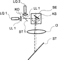
图2示出了根据本发明的具有在用于扫描照射的光路中的翻转镜的眼科设备的示意性构造; Figure 2 shows a schematic configuration of an ophthalmic device with a flip mirror in the light path for scanning illumination according to the present invention;
图3示出了根据本发明的具有在用于扫描照射的光路中的两个翻转镜的眼科设备的示意性构造;以及 Figure 3 shows a schematic configuration of an ophthalmic device with two inverted mirrors in the optical path for scanning illumination according to the invention; and
图4示出了用于将两个激光源耦合到用于扫描照射的光路中的变型方案。 FIG. 4 shows a variant for coupling two laser sources into the beam path for scanning irradiation. the
具体实施方式 Detailed ways
为了更好地图解说明所提出的技术方案,首先再一次深入探讨公知现有技术。为此,图1示出了公知眼底相机的示意性构造。 In order to better illustrate the proposed technical solution, the known prior art is firstly discussed again in depth. To this end, FIG. 1 shows a schematic configuration of a known fundus camera. the
在根据现有技术的眼底相机中,从照射源BQ发出的照射光BL通过有孔镜(Lochspiegel)LS和成像光学元件AO穿过瞳孔P被成像到眼睛的视网膜R上。由眼睛的视网膜R所反射的用于成像的光穿过眼睛的瞳孔P通过成像光学元件AO并且穿过有孔镜LS被成像到探测器D上。在此,由视网膜R的在成像光学元件AO与有孔镜LS之间的影像产生中间图像Z,并且该中间图像Z穿过有孔镜LS的孔径被成像到CCD相机形式的探测器D上。 In the fundus camera according to the prior art, the illumination light BL emitted from the illumination source BQ is imaged onto the retina R of the eye through the pupil P through the apertured mirror LS and the imaging optics AO. Light for imaging reflected by the retina R of the eye is imaged onto a detector D through the pupil P of the eye through the imaging optics AO and through the apertured mirror LS. Here, an intermediate image Z is generated from the image of the retina R between the imaging optics AO and the apertured mirror LS and is imaged through the aperture of the apertured mirror LS onto a detector D in the form of a CCD camera . the
在此,由照射源产生白照射光BL或红外照射光BL。在此,白光一方面可以作为常规光源-例如白炽灯或卤素灯的连续光谱被发射,或者另一方面可以由多个具有光谱上不同的发射(例如红、绿、蓝)的光源(例如LED)加性混合而成。在此,该照射直到晶状体(Augenlinse)都是环形的,使得在角膜的中心留下未被照射的区域,通过所述区域进行观察。 Here, white irradiation light BL or infrared irradiation light BL is generated by the irradiation source. Here, white light can be emitted on the one hand as a continuous spectrum of conventional light sources, such as incandescent lamps or halogen lamps, or on the other hand can be produced by a plurality of light sources (such as LEDs) with spectrally different emissions (such as red, green, blue). ) are additively mixed. In this case, the irradiation is annular up to the lens, so that an unirradiated area remains in the center of the cornea, through which the observation takes place. the
如已经提到的那样,眼底相机是眼科学中最重要的诊断仪器之一。尽管借助于眼底相机可以拍摄眼底的宽视场图像,并且由此得出诊断,但是利用该系统不能进行通过凝结的治疗。 As already mentioned, fundus cameras are one of the most important diagnostic instruments in ophthalmology. Although wide-field images of the fundus can be recorded with the aid of a fundus camera and a diagnosis can be derived therefrom, treatment by coagulation is not possible with this system. the
根据本发明的用于观察、检查、诊断和/或治疗眼睛的眼科设备由下列项目构成:照射光路,其从第一照射源出发通向眼睛并且具有有孔镜和成像光学元件;以及观察光路,其从眼睛出发通过该成像光学元件并且穿过该有孔镜通向探测器。此外,该眼科设备具有用于扫描照射的光路,该光路从第二照射源出发通向眼睛并且除了成像光学元件以外还具有扫描单元、物镜和分束器。在此,成像光学元件以及整个光路都被实施为使得它们没有内部反射。被布置在用于扫描照射的光路中的扫描单元被构造成一个以静电和/或电流测定方式被驱动的双向翻转镜(Kippspeigel)或者两个以静电和/或电流测定方式被驱动的单向翻转镜。在使用两个以静电和/或电流测定方式被驱动的单向翻转镜的情况下,优选地进行所述镜到彼此上的中间成像。 An ophthalmic device according to the invention for observing, examining, diagnosing and/or treating the eye consists of the following items: an illumination beam path, which leads from a first illumination source to the eye and has a perforated mirror and imaging optics; and an observation beam path , which leads from the eye through the imaging optics and through the apertured mirror to the detector. Furthermore, the ophthalmic device has a beam path for the scanning radiation, which leads from the second radiation source to the eye and has, in addition to the imaging optics, a scanning unit, an objective lens and a beam splitter. Here, the imaging optics as well as the entire beam path are embodied in such a way that they are free of internal reflections. The scanning unit arranged in the beam path for the scanning illumination is configured as an electrostatically and/or amperometrically driven bidirectional mirror (Kippspeigel) or as two electrostatically and/or agalvanically driven unidirectional flip mirror. When using two electrostatically and/or amperometrically driven one-way mirrors, an intermediate imaging of the mirrors onto one another is preferably carried out. the
将整个光路以及尤其是成像光学元件实施成无反射的是所提出的技术方案的功能的重要前提,因为否则在成像物镜中被反射的激光导致用于成像的照射在相机上过亮。 Making the entire beam path and especially the imaging optics nonreflective is an important prerequisite for the functionality of the proposed solution, since otherwise the reflected laser light in the imaging objective would cause the radiation used for imaging to be too bright on the camera. the
在第一有利的扩展方案中,扫描单元以MEMS技术被实施并且被用于准静态的运行。在此,扫描单元能够补偿激光光源或成像光学元件的横向色差。在此,该补偿优选地可以对不同的波长顺序地进行。因此,可以以高的可再现性在不同的波长、特别是在存在光学成像误差的情况下也保证激光斑在视网膜上的位置。用于校正成像光学元件的横向色差以及由此校正不同波长的激光斑在视网膜上的位置的另一可能性是使用预先经过色彩校正的扫描物镜。 In a first advantageous refinement, the scanning unit is embodied in MEMS technology and is used for quasi-static operation. Here, the scanning unit can compensate for lateral chromatic aberrations of the laser light source or of the imaging optics. In this case, the compensation can preferably be performed sequentially for different wavelengths. The position of the laser spot on the retina can thus be guaranteed with high reproducibility even at different wavelengths, in particular in the presence of optical imaging errors. Another possibility for correcting the lateral chromatic aberration of the imaging optics and thus the position of the laser spots of different wavelengths on the retina is to use pre-color-corrected scanning objectives. the
在第二有利的扩展方案中,为了补偿眼睛的视觉障碍,以可移动的方式布置至少一个光学组件。这可以要么是被布置在用于扫描照射的光路中的物镜,要么是用于将激光准直校准到扫描单元上而存在的准直光学元件。在此,在使用多个激光器的情况下可以移动一个或多个准直光学元件。 In a second advantageous refinement, at least one optical component is arranged in a displaceable manner in order to compensate for visual impairments of the eyes. This can either be an objective lens arranged in the beam path for the scanning illumination, or a collimation optic present for collimating the laser light onto the scanning unit. In this case, one or more collimation optics can be moved when using several lasers. the
在此保证:尽管存在视觉障碍,但是仍然进行激光斑在视网膜上的精确到点的成像。为此,视觉障碍优选地由眼科设备-例如在眼底相机的情况下-利用球体以及可选的圆柱体的值或更高阶误差自动地确 定,并且在将激光成像到视网膜上时被加以考虑。 It is hereby guaranteed that despite visual disturbances, a spot-precise imaging of the laser spot on the retina takes place. For this purpose, the visual impairment is preferably automatically determined by the ophthalmic device - for example in the case of a fundus camera - using the values of spheres and optionally cylinders or higher order errors, and is applied when imaging the laser light onto the retina. consider. the
在另一有利的扩展方案中,眼科设备具有用于示出标记以及在其形状、波长、强度以及脉冲宽度和脉冲序列方面对其进行改变的装置。由已存在的控制单元在形状、波长、强度、以及脉冲宽度和脉冲序列方面改变由照射光源所发射的光并且监测这些方面的阈值。 In a further advantageous refinement, the ophthalmic device has means for representing the markers and changing them with respect to their shape, wavelength, intensity and pulse width and pulse sequence. The light emitted by the illumination source is varied with respect to shape, wavelength, intensity, and pulse width and pulse sequence by an existing control unit and threshold values for these are monitored. the
在达到该阈值的情况下或在其它不可预见的事件的情况下,可以由控制单元通过不同的与安全相关的部件通过关闭激光源来中断诊断或治疗。为此,还由控制单元进行激光斑在视网膜上的位置监控,以便将可能的故障情况减少到接近于零的最小值。 If this threshold value is reached or in the case of other unforeseen events, the diagnosis or treatment can be interrupted by the control unit via various safety-related components by switching off the laser source. For this purpose, the position of the laser spot on the retina is also monitored by the control unit in order to reduce possible fault situations to a near-zero minimum. the
在此,所存在的安全机制必须以专门在故障情况下将目标射束和治疗射束的激光能量减小到非临界的最小值的这一精确度和速度工作。此外,所存在的安全机制应当彼此无关地以及与由使用者造成的可能的故障条件无关地工作。 In this case, the existing safety mechanism must work with such precision and speed that it reduces the laser energy of the target beam and the treatment beam to a non-critical minimum value, especially in the event of a fault. Furthermore, the existing safety mechanisms should work independently of each other and of possible fault conditions caused by the user. the
对本发明重要的另一特征可以看成是耦合进扫描照射。为此,在用于扫描照射的光路中所存在的被实施为二向色性或与偏振有关的分束器被布置为使得第二照射源通过扫描单元和物镜被中心地成像到眼瞳孔中。 Another feature important to the invention can be seen as coupling into scanning illumination. For this purpose, the dichroic or polarization-dependent beam splitter present in the beam path for the scanning illumination is arranged such that the second illumination source is imaged centrally into the pupil of the eye via the scanning unit and the objective . the
对此,图2示出了根据本发明的具有用于对眼睛进行扫描照射的光路的眼科设备的示意性构造。在此,从照射源BQ发出的照射光BL通过有孔镜LS和成像光学元件AO穿过瞳孔P也被成像到眼睛的视网膜R上,并且被眼睛的视网膜R反射的用于成像的光穿过眼睛的瞳孔P通过成像光学元件AO在形成中间图像Z的情况下穿过有孔镜LS的孔径被成像到探测器D上。在此,作为探测器D通常也使用CCD相机或CMOS相机。 To this end, FIG. 2 shows a schematic configuration of an ophthalmic device according to the invention with a beam path for scanning illumination of the eye. Here, the illumination light BL emitted from the illumination source BQ passes through the pupil P through the apertured mirror LS and the imaging optical element AO and is also imaged onto the retina R of the eye, and the light for imaging reflected by the retina R of the eye passes through the pupil P. The pupil P of the eye is imaged onto the detector D via the imaging optics AO through the aperture of the apertured mirror LS while forming the intermediate image Z. A CCD camera or a CMOS camera is usually used here as detector D as well. the
附加于该公知的装置,根据本发明的用于观察、检查、诊断和/或治疗眼睛的眼科设备还具有用于扫描照射的光路。激光源LQ的激光LL通过准直光学元件KO、扫描单元SE、物镜O和分束器ST被成像到眼睛的视网膜R上,其中扫描单元SE具有单个以静电和/或电流测定方式被驱动的双向的翻转镜KS。在此,被实施为二向色性或与偏振有关的分束器ST被布置为使得激光源LQ的激光LL被中心地成像到眼睛的瞳孔P中。 In addition to this known device, the ophthalmic device according to the invention for observing, examining, diagnosing and/or treating the eye also has a beam path for scanning illumination. The laser light LL of the laser source LQ is imaged onto the retina R of the eye via the collimating optics KO, the scanning unit SE, the objective lens O and the beam splitter ST, wherein the scanning unit SE has individual electrostatically and/or amperometrically driven Two-way flip mirror KS. Here, the dichroic or polarization-dependent beam splitter ST is arranged such that the laser light LL of the laser light source LQ is imaged centrally into the pupil P of the eye. the
扫描单元SE的移动以及与之相联系的激光LL的偏转角的改变对应 于激光LL在眼睛的瞳孔P中的角度改变,并且由此对应于激光斑在视网膜R上的位置改变。在此,激光到眼睛中的入射条件-例如射束直径和角膜上的数值孔径对应于在狭缝灯的隐形眼镜的出射处的用于对视网膜执行治疗干预的入射条件。但是与之不同的是,没有为了补偿眼睛的屈光度而使用隐形眼镜。 The movement of the scanning unit SE and the associated change in the deflection angle of the laser light LL corresponds to a change in the angle of the laser light LL in the pupil P of the eye and thus to a change in the position of the laser spot on the retina R. In this case, the incidence conditions of the laser light into the eye, such as the beam diameter and the numerical aperture on the cornea, correspond to the incidence conditions at the exit of the contact lens of the slit lamp for carrying out the therapeutic intervention on the retina. But unlike it, no contact lenses are used to compensate for the diopter of the eye. the
激光的诊断或治疗性的使用要求激光斑在可到达的扫描区域内的视网膜R上的自由定位能力。由于扫描单元SE到眼睛的瞳孔P中的成像,有利的是使用单个扫描镜。以MEMS技术实施的以静电和/或电流测定方式被驱动的双向翻转镜所具有的优点是,其可以在准静态运行中围绕两个轴中的旋转点翻转。 The diagnostic or therapeutic use of laser light requires free positioning of the laser spot on the retina R within the accessible scanning range. Due to the imaging of the scanning unit SE into the pupil P of the eye it is advantageous to use a single scanning mirror. Electrostatically and/or amperometrically driven bidirectional flip mirrors implemented in MEMS technology have the advantage that they can swivel about points of rotation in two axes during quasi-static operation. the
可替代地,也可以如图3中所示的那样将两个单向的翻转镜用作扫描单元SE。在此,被证明有利的是,借助于中间光学元件将第一翻转镜成像到第二翻转镜上,因为否则扫描单元SE的之后的成像仅能对所述镜中最多一个最佳地进行。 Alternatively, two unidirectional flip mirrors can also be used as scanning unit SE, as shown in FIG. 3 . In this case, it has proven to be advantageous to image the first reversing mirror onto the second reversing mirror by means of an intermediate optical element, since otherwise the subsequent imaging of the scanning unit SE can only take place optimally for at most one of the mirrors. the
附加于已经描述的装置(根据图2),光源LQ的激光LL通过准直光学元件KO、具有两个以静电和/或电流测定方式被驱动的单向翻转镜KS1和KS2的扫描单元SE、物镜O和分束器ST被成像到眼睛的视网膜R上。在此,被实施为二向色性或与偏振有关的分束器ST被布置为使得激光源LQ的激光LL被中心地成像到眼睛的瞳孔P中。在两个翻转镜KS1和KS2之间布置有中间光学元件ZO,以便将第一翻转镜KS1成像到第二翻转镜KS2上。在此,物镜O与分束器ST和成像光学元件AO一起也保证扫描单元SE到眼睛的瞳孔P中的成像。 In addition to the device already described (according to FIG. 2 ), the laser light LL of the light source LQ passes through the collimating optical element KO, the scanning unit SE with two electrostatically and/or amperometrically driven one-way mirrors KS1 and KS2, The objective lens O and the beam splitter ST are imaged onto the retina R of the eye. Here, the dichroic or polarization-dependent beam splitter ST is arranged such that the laser light LL of the laser light source LQ is imaged centrally into the pupil P of the eye. An intermediate optical element ZO is arranged between the two reversing mirrors KS1 and KS2 in order to image the first reversing mirror KS1 onto the second reversing mirror KS2 . Here too, the objective O together with the beam splitter ST and the imaging optics AO ensures the imaging of the scanning unit SE into the pupil P of the eye. the
所述翻转镜所具有的特性是,在静电驱动时所施加的直流电压U的情况下翻转与该电压成比例的角度θ并且在直流电压U的值变化以前一直保持该位置。由此实现对被偏转的激光的限定的静态定位。在以电流测定方式驱动的情况下,该镜借助于流经与该镜相连接的线圈的直流电流I被静态地偏转与该电流成比例的角度θ。 The reversible mirror has the property that, when a DC voltage U is applied during electrostatic driving, it is reversed by an angle θ proportional to this voltage and remains in this position until the value of the DC voltage U changes. A defined static positioning of the deflected laser light is thereby achieved. In the case of amperometric drive, the mirror is deflected statically by an angle θ proportional to this current by means of a direct current I flowing through a coil connected to the mirror. the
此外,利用根据本发明的装置可以同时将第二照射源的多个单独光束以扫描的方式投射到眼睛上。为此,第二照射源由激光源形式的多个单独光源以及为了能够同时耦合进所述单独光束所需的分束器和准直光学元件构成,所述分束器和准直光学元件分别存在于用于扫描照射的光路中的扫描单元之前。 Furthermore, with the device according to the invention it is possible to simultaneously project a plurality of individual light beams of the second radiation source onto the eye in a scanning manner. For this purpose, the second radiation source consists of a plurality of individual light sources in the form of a laser source and the beam splitter and collimating optics required to be able to couple in said individual beams simultaneously, said beam splitter and collimating optics being respectively Presence of the scanning unit in the light path for scanning illumination. the
对此,图4示出了用于将两个激光源耦合到用于扫描照射的光路中的变型方案。在此,激光源LQ由两个激光源LQ1和LQ2构成,所述激光源的被准直校准的激光束LL1和LL2通过准直光学元件KO1和准直光学元件KO2、以及扫描单元SE和物镜O之前的分束器ST1被耦合到用于扫描照射的光路中。在此,物镜O与分束器ST和成像光学元件AO一起保证扫描单元SE、即所有同时被成像到那里的激光束LL到眼睛的瞳孔P中的成像。 To this end, FIG. 4 shows a variant for coupling two laser sources into the beam path for scanning irradiation. The laser source LQ here consists of two laser sources LQ1 and LQ2 whose collimated laser beams LL1 and LL2 pass through the collimating optical element KO1 and the collimating optical element KO2 as well as the scanning unit SE and the objective lens A beam splitter ST1 before O is coupled into the beam path for scanning illumination. In this case, the objective O together with the beam splitter ST and the imaging optics AO ensure the imaging of the scanning unit SE, ie all the laser beams LL simultaneously imaged there, into the pupil P of the eye. the
在此,激光源LQ也可以由两个以上激光源LQ构成,这些激光源的激光束LL通过扫描单元SE之前的准直光学元件KO以及分束器ST被耦合到用于扫描照射的光路中。 Here, the laser source LQ can also consist of more than two laser sources LQ, the laser beams LL of which are coupled into the beam path for the scanning irradiation via the collimating optical element KO upstream of the scanning unit SE and the beam splitter ST . the
装置的该变型方案例如可以被用于除了用于荧光检查等的治疗或激励射束以外还将附加的处于可见光谱范围中的目标射束投射到眼睛中。 This variant of the device can be used, for example, to project an additional target beam in the visible spectral range into the eye in addition to the treatment or excitation beam for fluoroscopy or the like. the
造成有利影响的是,两个照射光源的光束在眼睛的光学界面处被扩展,使得与激光斑在视网膜上的成像相比,向探测器方向上的反射具有小的强度。因此保证:尽管激光具有高辐射强度,仍然可以在不过亮的情况下对目标激光和治疗激光进行电子观察。在此,可能有利的是,在探测器之前通过滤光片进行衰减。 Advantageously, the light beams of the two illumination sources are expanded at the optical interface of the eye, so that the reflection in the direction of the detector has a lower intensity than the imaging of the laser spot on the retina. It is thus guaranteed that, despite the high radiation intensity of the laser light, electronic observation of the target laser light and the treatment laser light is still possible without excessive brightness. In this case, it may be advantageous to perform attenuation via optical filters upstream of the detector. the
在另一有利的扩展方案中,存在用于图像处理和图像分析以及用于记录和存储图像数据和病人数据的装置。在此,该眼科设备为了在线观察眼睛而具有目镜和/或监视器或显示器。 In a further advantageous refinement, there are devices for image processing and image analysis as well as for recording and storing image data and patient data. In this case, the ophthalmic device has eyepieces and/or a monitor or display for the on-line observation of the eye. the
为此,优选地存在计算单元,所述计算单元在制作以及诊断陈述和治疗计划方面对使用者进行支持。此外,所述计算单元用于确定所有的控制数据和监测整个应用。 For this purpose, a computing unit is preferably present, which supports the user in the preparation of the diagnostic statement and the treatment plan. Furthermore, the computing unit is used to determine all control data and to monitor the entire application. the
为了执行诊断和/或治疗,存在于用于扫描照射的光路中的扫描单元SE被控制单元控制为使得第二照射源BQ的光穿过眼睛的瞳孔P被成像到视网膜R的有关区域上。 To perform diagnosis and/or therapy, the scanning unit SE present in the optical path for scanning illumination is controlled by the control unit such that the light of the second illumination source BQ is imaged onto the relevant area of the retina R through the pupil P of the eye. the
通过聚焦到视网膜上的激光,例如可以借助组织的所发射的光(后向散射,自体荧光)或者通过造影剂所注入的荧光提供有说服力的诊断。另一方面,聚焦到视网膜上的激光也可以在足够高的能量密度的情况下被用于治疗目的,例如机械固定视网膜或者影响新陈代谢过程。 A convincing diagnosis can be made, for example, by means of the light emitted by the tissue (backscattering, autofluorescence) or by the fluorescence injected by a contrast agent by means of the laser light focused on the retina. On the other hand, laser light focused on the retina can also be used at sufficiently high energy densities for therapeutic purposes, such as mechanically immobilizing the retina or influencing metabolic processes. the
对此有利的是,第二照射源的强度可以被衰减,使得除了光凝结以 外还可以进行其它的激光治疗类型,例如通过对视网膜的区域进行局部加热进行的生物刺激。 It is advantageous here that the intensity of the second radiation source can be attenuated, so that in addition to photocoagulation other types of laser therapy can be performed, such as biostimulation by localized heating of the retinal region. the
在此有利的是使用宽视场照射,因为通过诊断/治疗和成像的去耦合可以在线监测诊断和/或治疗过程。由此在诊断和治疗期间,可以进行对激光斑在视网膜上的位置的持久监控。此外,可以监测所激活的激光斑在视网膜上的光学反应,确定相关的测量值,以及在达到预先给定的阈值的情况下促使关闭照射光源。 The use of wide-field illumination is advantageous here, since the diagnosis and/or treatment process can be monitored online due to the decoupling of diagnosis/therapy and imaging. Permanent monitoring of the position of the laser spot on the retina is thus possible during diagnosis and treatment. In addition, the optical response of the activated laser spot on the retina can be monitored, the associated measured values can be determined, and a switch-off of the irradiation light source can be brought about if a predetermined threshold value is reached. the
在另一有利的扩展方案中,第二照射源可以被用于将标记形式的光投射到眼睛中。由此,可以通过将眼睛固定到该标记上来对病人的注视方向进行有针对性的定向,以便检查眼睛的周边区域。 In a further advantageous refinement, the second radiation source can be used to project light in the form of markings into the eye. The direction of gaze of the patient can thus be oriented in a targeted manner by fixing the eye to the marker in order to examine the peripheral region of the eye. the
所得出的另一有利的扩展方案是,由第二照射源将时间上和位置上可变的光标记和/或明亮波带(Leuchtfeld)投射到眼睛中,其中所述光标记和/或明亮波带的可辨认性由病人通过合适的装置来确认。由此,根据本发明的眼科设备甚至可以被用于视野检查、即确定病人的视场。由此,时间上和位置上可变的光标记和/或明亮波带的数据以及由病人确认/未由病人确认的可辨认性被记录和存储。 A further advantageous development results in that temporally and positionally variable light signatures and/or bright bands (Leuchtfeld) are projected into the eye by the second illumination source, wherein the light signatures and/or bright The identifiability of the wave bands is confirmed by the patient with a suitable device. Thus, the ophthalmic device according to the invention can even be used for perimetry, ie for determining the visual field of a patient. The data of temporally and positionally variable light marks and/or bright bands as well as patient-confirmed/non-patient-confirmed recognizability are thus recorded and stored. the
为此,在宽视场照射(第一照射源)的情况下,具有可变的XY偏转的标记(第二照射源)被投射到视网膜上。在此,所述光斑有利地尤其是在不同强度(几μW至激光器类型1的极限值)以及时间调制(例如具有不同脉冲宽度和频率的闪烁)的情况下具有不同的几何形状,例如十字、环、点等。 To this end, in the case of wide-field illumination (first illumination source), a marker with variable XY deflection (second illumination source) is projected onto the retina. In this case, the light spots advantageously have different geometries, for example crosses, rings, dots, etc. the
病人对标记的可辨认性的主观反馈例如通过按下按钮被接收、记录和分析。 Subjective patient feedback on the legibility of the markers is received, recorded and analyzed, for example by pressing a button. the
在此,也可以通过使用宽视场照射在视野检查期间持久地监控标记在视网膜上的位置。因此,可以通过操作者的在线监测来简单地检验病人对可辨认性的反馈的合理性。 Here too, the position of the marker on the retina can be permanently monitored during the perimetry by using wide-field illumination. Therefore, the plausibility of the patient's feedback on intelligibility can be checked simply by online monitoring by the operator. the
在另一有利的扩展方案中,可以将根据本发明的装置用于对眼睛进行荧光成像。眼睛中的荧光激励借助于第二照射源进行,所述第二照射源为此发射紫外光谱、可见光谱或红外光谱。然后,在眼睛中发起的荧光信号优选地由选择波长的探测器来接收。 In a further advantageous configuration, the device according to the invention can be used for fluorescent imaging of the eye. The excitation of fluorescence in the eye takes place by means of a second radiation source which emits for this purpose the ultraviolet, visible or infrared spectrum. The fluorescent signal initiated in the eye is then preferably received by a wavelength-selective detector. the
在此,造成特别有利的影响的是,将发射超短脉冲的激光器用作用于扫描照射的照射源。在此,眼睛中的荧光激励也利用紫外光谱、可 见光谱或红外光谱来进行,其中脉冲长度处于ns、ps或fs的范围。但是在此为了记录眼睛中发起的荧光,使用高时间分辨能力的探测器,例如根据TCSPC原理(time correlated single photon counting(时间相关单光子计数))工作的探测器。利用根据本发明的装置的该特别的扩展方案,可以执行眼睛的荧光寿命成像。 It is particularly advantageous here if a laser emitting ultrashort pulses is used as the radiation source for the scanning radiation. Here too, fluorescence excitation in the eye takes place using the UV, visible or infrared spectrum, with pulse lengths in the ns, ps or fs range. However, in order to record the fluorescence initiated in the eye, a highly time-resolving detector is used here, for example a detector operating according to the TCSPC principle (time correlated single photon counting). With this particular embodiment of the device according to the invention, fluorescence lifetime imaging of the eye can be performed. the
作为用于观察、检查、诊断和/或治疗眼睛的眼科设备的另一有利的扩展方案,一方面是使用目标激光,所述目标激光在诊疗激光的诊疗期间(诊断或治疗)被跟踪。由此可以较简单地观察诊疗。另一方面,可以通过使用眼动仪(Eye-Tracker)监测视网膜的运动,使得减小由于眼睛运动造成的诊疗失误。眼动仪既可以监测眼睛的位置又可以监测其取向(注视方向)。 As a further advantageous development of the ophthalmic device for observing, examining, diagnosing and/or treating the eye, on the one hand a target laser is used which is tracked during the treatment (diagnosis or treatment) of the diagnostic laser. This makes observation and treatment easier. On the other hand, the movement of the retina can be monitored by using an eye tracker (Eye-Tracker), so that the diagnosis and treatment errors caused by eye movement can be reduced. Eye trackers monitor both the position and orientation (direction of gaze) of the eyes. the
在根据本发明的用于观察、检查、诊断和/或治疗眼睛的眼科方法中,为了观察和检查而由第一照射源通过所存在的有孔镜和成像光学元件来照射眼睛,并且从眼睛发出的光通过该成像光学元件穿过该有孔镜被成像到探测器上。附加地,为了诊断和/或治疗而由第二照射源通过扫描单元、物镜、分束器和该成像光学元件来照射眼睛,其中扫描单元以一个或多个翻转镜的形式被以静电和/或电流测定的方式双向地驱动。在此,成像光学元件以及整个光路可以被实施为使得不出现内部反射。 In the ophthalmic method according to the invention for observing, examining, diagnosing and/or treating the eye, the eye is irradiated for observation and examination by a first source of illumination through the existing apertured mirror and imaging optics, and from the eye The emitted light is imaged onto the detector through the imaging optical element through the apertured mirror. In addition, the eye is irradiated for diagnosis and/or therapy by a second radiation source via the scanning unit, the objective, the beam splitter and the imaging optics, wherein the scanning unit is electrostatically and/or in the form of one or more flipping mirrors Or current measurement way to drive bidirectionally. In this case, the imaging optics as well as the entire beam path can be designed such that no internal reflections occur. the
将整个光路、以及尤其是成像光学元件实施成无反射的是所提出的技术方案的功能的重要前提,因为否则在成像物镜中被反射的激光导致用于成像的照射在相机上过亮。 Making the entire beam path, and especially the imaging optics, non-reflective is an important prerequisite for the functionality of the proposed solution, since otherwise the reflected laser light in the imaging objective would cause the radiation used for imaging to be too bright on the camera. the
在此,对诊断和/或治疗造成特别有利的影响的是,扫描单元以MEMS技术被实施成一个双向或两个单向的以静电和/或电流测定方式被驱动的翻转镜的形式,并且准静态地运行。由此,扫描单元能够补偿激光光源或成像光学元件的横向色差。在此,该补偿优选地可以对不同的波长顺序地进行。用于校正成像光学元件的横向色差以及由此校正不同波长的激光斑在视网膜上的位置的另一可能性是使用预先经过色彩校正的扫描物镜。因此,也可以在不同激光波长的情况下尤其是在存在光学成像误差的情况下以高的可再现性保证激光斑在视网膜上的位置。 In this case, it is particularly advantageous for diagnosis and/or therapy if the scanning unit is implemented in MEMS technology in the form of a bidirectional or two unidirectional electrostatically and/or amperometrically driven reversing mirrors, and operates quasi-statically. Thereby, the scanning unit is able to compensate for lateral chromatic aberrations of the laser light source or the imaging optics. In this case, the compensation can preferably be performed sequentially for different wavelengths. Another possibility for correcting the lateral chromatic aberration of the imaging optics and thus the position of the laser spots of different wavelengths on the retina is to use pre-color-corrected scanning objectives. The position of the laser spot on the retina can thus be guaranteed with high reproducibility also in the case of different laser wavelengths, in particular in the presence of optical imaging errors. the
此外,在扫描照射时可以通过在用于扫描照射的光路中以可移动的 方式布置至少一个光学组件来补偿所存在的眼睛的视觉障碍。这可以要么是被布置在用于扫描照射的光路中的物镜,要么是用于将激光准直校准到扫描单元上而存在的准直光学元件。在此,在使用多个激光器的情况下可以移动一个或多个准直光学元件。在此保证:尽管存在视觉障碍,但是仍然进行激光斑在视网膜上的精确到点的成像。为此,视觉障碍优选地由眼科设备-例如在眼底相机的情况下-利用球体以及可选的圆柱体的值或更高阶误差自动地确定,并且在将激光成像到视网膜上时被加以考虑。 In addition, existing visual impairments of the eyes can be compensated during the scanning irradiation by displaceably arranging at least one optical component in the beam path for the scanning irradiation. This can either be an objective lens arranged in the beam path for the scanning illumination, or a collimation optic present for collimating the laser light onto the scanning unit. In this case, one or more collimation optics can be moved when using several lasers. It is hereby guaranteed that despite visual disturbances, a spot-precise imaging of the laser spot on the retina takes place. For this purpose, visual disturbances are preferably automatically determined by the ophthalmic device—for example in the case of a fundus camera—using the values of spheres and optionally cylinders or higher order errors, and are taken into account when imaging the laser light onto the retina . the
为了针对在观察和检查或诊断和/或治疗(即诊疗)眼睛时的不同任务能够优化第二照射源,第二照射源能够将光斑或者标记成像到视网膜上,所述光斑或标记在其形状、波长、强度以及脉冲宽度和脉冲序列方面变化并且其阈值被监测。 In order to be able to optimize the second illumination source for different tasks when observing and examining or diagnosing and/or treating (i.e. diagnosis and treatment) the eye, the second illumination source can image a light spot or a mark on the retina, said light spot or mark in its shape , wavelength, intensity, and pulse width and pulse sequence changes and their thresholds are monitored. the
在达到该阈值的情况下或在其它不可预见的事件的情况下,可以由控制单元通过不同的与安全相关的部件通过关闭激光源来中断诊断或治疗。为此,还由控制单元进行激光斑在视网膜上的位置监控,以便将可能的故障情况减少到接近于零的最小值。 If this threshold value is reached or in the case of other unforeseen events, the diagnosis or treatment can be interrupted by the control unit via various safety-related components by switching off the laser source. For this purpose, the position of the laser spot on the retina is also monitored by the control unit in order to reduce possible fault situations to a near-zero minimum. the
在此,所存在的安全机制必须以专门在故障情况下将目标射束和治疗射束的激光能量减小到非临界的最小值的这一精确度和速度工作。此外,所存在的安全机制应当彼此无关地以及与由使用者造成的可能的故障条件无关地工作。 In this case, the existing safety mechanism must work with such precision and speed that it reduces the laser energy of the target beam and the treatment beam to a non-critical minimum value, especially in the event of a fault. Furthermore, the existing safety mechanisms should work independently of each other and of possible fault conditions caused by the user. the
对本发明重要的另一方法步骤是耦合进扫描照射。为此,在用于扫描照射的光路中所存在的被实施为二向色性或与偏振有关的分束器被布置为使得第二照射源通过扫描单元和物镜被中心地成像到眼瞳孔中。 Another method step essential to the invention is the incorporation of scanning irradiation. For this purpose, the dichroic or polarization-dependent beam splitter present in the beam path for the scanning illumination is arranged such that the second illumination source is imaged centrally into the pupil of the eye via the scanning unit and the objective . the
如已经描述的那样,在本发明的眼科方法中从第一照射源发出的光通过有孔镜和成像光学元件穿过瞳孔被成像到眼睛的视网膜上,并且被眼睛的视网膜反射的用于成像的光穿过眼睛的瞳孔通过成像光学元件在形成中间图像的情况下穿过有孔镜的孔径被成像到探测器上。在此,作为探测器通常也使用CCD相机或CMOS相机。附加于该公知的方法,为了通过用于扫描照射的光路诊断和/或治疗眼睛,第二照射源的光通过扫描单元、物镜和分束器被成像到眼睛的视网膜上。在此,被实施为二向色性或与偏振有关的分束器被布置为使得第二照射源的光 被中心地成像到眼睛的瞳孔中。在此,第二照射源由至少一个、但优选多个激光源构成,所述激光源的被准直校准的射束通过在扫描单元和物镜之前的分束器被耦合到用于扫描照射的光路中。 As already described, in the ophthalmic method of the present invention, the light emitted from the first illumination source is imaged onto the retina of the eye through the apertured mirror and the imaging optics through the pupil, and is reflected by the retina of the eye for imaging The light passing through the pupil of the eye is imaged onto the detector through the aperture of the apertured mirror through the imaging optics to form an intermediate image. In this case, CCD cameras or CMOS cameras are usually also used as detectors. In addition to this known method, for the diagnosis and/or treatment of the eye via the beam path for scanning radiation, the light of the second radiation source is imaged onto the retina of the eye via a scanning unit, an objective lens and a beam splitter. Here, the dichroic or polarization-dependent beam splitter is arranged such that the light of the second illumination source is imaged centrally into the pupil of the eye. In this case, the second radiation source is formed by at least one, but preferably a plurality of laser sources, whose collimated beams are coupled via a beam splitter upstream of the scanning unit and the objective to the scanning radiation source. in the light path. the
扫描单元的移动以及与之相联系的光偏转角的改变对应于光在眼睛的瞳孔中的角度改变,并且由此对应于光斑在视网膜上的位置改变。在此,激光在入射到眼睛中的条件-例如射束直径和角膜上的数值孔径对应于在使用狭缝灯的情况下隐形眼镜的出射处的用于对视网膜执行治疗干预的条件。但是与之不同的是,没有为了补偿眼睛的屈光度而使用隐形眼镜。 A movement of the scanning unit and an associated change in the light deflection angle corresponds to a change in the angle of the light in the pupil of the eye and thus to a change in the position of the light spot on the retina. In this case, the conditions at which the laser light enters the eye, such as the beam diameter and the numerical aperture at the cornea, correspond to the conditions at the exit of the contact lens when using a slit lamp for performing a therapeutic intervention on the retina. But unlike it, no contact lenses are used to compensate for the diopter of the eye. the
激光的诊断或治疗性的使用要求激光斑在可到达的扫描区域内在视网膜上的自由定位能力。由于扫描单元到眼睛的瞳孔中的成像,有利的是使用单个扫描镜。以MEMS技术实施的以静电和/或电流测定方式被驱动的双向翻转镜所具有的优点是,其可以在准静态运行中围绕两个轴中的旋转点翻转。可替代地,也可以将两个单向的翻转镜用作扫描单元。在此,被证明有利的是,借助于中间光学元件将第一翻转镜成像到第二翻转镜上,因为否则扫描单元的之后的成像仅能对所述镜中最多一个最佳地进行。所述翻转镜所具有的特性是,在静电驱动时所施加的直流电压U的情况下翻转与该电压成比例的角度θ并且在直流电压U的值变化以前一直保持该位置。在以电流测定方式驱动的情况下,该镜借助于流经与该镜相连接的线圈的直流电流I被静态地偏转与该电流成比例的角度θ。由此实现对被偏转的激光的限定的静态定位。 The diagnostic or therapeutic use of laser light requires free positioning of the laser spot on the retina within the accessible scanning field. Due to the imaging of the scanning unit into the pupil of the eye it is advantageous to use a single scanning mirror. Electrostatically and/or amperometrically driven bidirectional flip mirrors implemented in MEMS technology have the advantage that they can swivel about points of rotation in two axes during quasi-static operation. Alternatively, two unidirectional flip mirrors can also be used as scanning unit. In this case, it has proven to be advantageous to image the first reversing mirror onto the second reversing mirror by means of an intermediate optical element, since otherwise the subsequent imaging of the scanning unit can only take place optimally for at most one of the mirrors. The reversible mirror has the property that, when a DC voltage U is applied during electrostatic driving, it is reversed by an angle θ proportional to this voltage and remains in this position until the value of the DC voltage U changes. In the case of amperometric drive, the mirror is deflected statically by an angle θ proportional to this current by means of a direct current I flowing through a coil connected to the mirror. A defined static positioning of the deflected laser light is thereby achieved. the
此外,利用根据本发明的方法可以同时将第二照射源的多个单独光束以扫描的方式投射到眼睛上。为此,第二照射源由多个以激光源形式的单独光源构成,其中所述激光源的单独射束可以通过分束器和准直光学元件被耦合到用于扫描照射的光路中,并且可以同时通过扫描单元被投射到眼睛中。 Furthermore, with the method according to the invention it is possible to simultaneously project a plurality of individual light beams of the second radiation source onto the eye in a scanning manner. For this purpose, the second radiation source consists of a plurality of individual light sources in the form of laser sources, wherein the individual beams of the laser sources can be coupled via beam splitters and collimating optics into the beam path for the scanning radiation, and can be projected into the eye by the scanning unit at the same time. the
在此,保证扫描单元的成像,也就是说所有同时被成像到那里的激光束都被以扫描方式投射到眼睛的瞳孔中。 In this case, the imaging of the scanning unit is ensured, ie all laser beams imaged there at the same time are projected into the pupil of the eye in a scanning manner. the
装置的该变型方案例如可以被用于除了用于荧光检查等的治疗或激励射束以外还将附加的处于可见光谱范围中的目标射束投射到眼睛中。 This variant of the device can be used, for example, to project an additional target beam in the visible spectral range into the eye in addition to the treatment or excitation beam for fluoroscopy or the like. the
造成有利影响的是,两个照射光源的光束在眼睛的光学界面处被扩展,使得与激光斑在视网膜上的成像相比,向探测器方向上的反射具有小的强度。因此保证:尽管激光具有高辐射强度,仍然可以在不过亮的情况下对目标激光和治疗激光进行电子观察。 Advantageously, the light beams of the two illumination sources are expanded at the optical interface of the eye, so that the reflection in the direction of the detector has a lower intensity than the imaging of the laser spot on the retina. It is thus guaranteed that, despite the high radiation intensity of the laser light, electronic observation of the target laser light and the treatment laser light is still possible without excessive brightness. the
对观察和检查以及诊疗而言都适宜的是,处理、分析、记录由探测器所拍摄的图像并将其与病人数据一起存储。为此,优选地使用计算单元,所述计算单元在制作诊断和治疗计划方面对使用者进行支持。此外,所述计算单元用于确定所有的控制数据和监测整个应用。除了该计算单元以外,为了在线观察眼睛而存在目镜和/或监视器或显示器。 Both for observation and examination as well as for diagnosis, it is expedient to process, analyze, record and store the images recorded by the detector together with the patient data. For this purpose, a computing unit is preferably used, which supports the user in preparing the diagnosis and treatment plan. Furthermore, the computing unit is used to determine all control data and to monitor the entire application. In addition to the computing unit, there are eyepieces and/or monitors or displays for the on-line observation of the eye. the
为了执行诊断和/或治疗,存在于用于扫描照射的光路中的扫描单元被控制单元控制为使得第二照射源的光穿过眼睛的瞳孔被成像到视网膜的有关区域上。 In order to perform diagnosis and/or therapy, the scanning unit present in the light path for the scanning illumination is controlled by the control unit such that the light of the second illumination source is imaged onto the relevant area of the retina through the pupil of the eye. the
通过聚焦到视网膜上的激光,例如可以借助组织的所发射的光(后向散射,自体荧光)或者通过造影剂所注入的荧光提供有说服力的诊断。另一方面,聚焦到视网膜上的激光也可以在足够高的能量密度的情况下用于治疗目的,例如机械固定视网膜或者影响新陈代谢过程。 A convincing diagnosis can be made, for example, by means of the light emitted by the tissue (backscattering, autofluorescence) or by the fluorescence injected by a contrast agent by means of the laser light focused on the retina. On the other hand, laser light focused onto the retina can also be used at sufficiently high energy densities for therapeutic purposes, such as mechanically immobilizing the retina or influencing metabolic processes. the
对此有利的是,第二照射源的强度可以被衰减,使得除了光凝结以外还可以进行其它的激光治疗类型,例如通过对视网膜的区域进行局部加热进行的生物刺激。 It is advantageous here that the intensity of the second radiation source can be attenuated, so that, in addition to photocoagulation, other types of laser therapy can be performed, for example biostimulation by local heating of regions of the retina. the
在此有利的是使用宽视场照射,因为通过诊断/治疗和成像的去耦合可以在线监测诊断和/或治疗过程。由此在诊断和治疗期间,可以进行对激光斑在视网膜上的位置的持久监控。此外,可以监测所激活的激光斑在视网膜上的光学反应,确定相关的测量值,以及在达到预先给定的阈值的情况下促使关闭照射光源。 The use of wide-field illumination is advantageous here, since the diagnosis and/or treatment process can be monitored online due to the decoupling of diagnosis/therapy and imaging. Permanent monitoring of the position of the laser spot on the retina is thus possible during diagnosis and treatment. In addition, the optical response of the activated laser spot on the retina can be monitored, the associated measured values can be determined, and a switch-off of the irradiation light source can be brought about if a predetermined threshold value is reached. the
根据本发明的方法也可以被用于在由第二照射源将标记形式的光投射到眼睛中时对病人的注视方向进行有针对性的定向,其中病人将所述标记用于对其注视方向进行定向。由此通过将眼固定到该标记上可以检查眼睛的周边区域。 The method according to the invention can also be used for the targeted orientation of the patient's gaze direction when light is projected into the eye by the second illumination source in the form of a marker, wherein the patient uses the marker for his gaze direction for orientation. The peripheral area of the eye can thus be examined by fixing the eye to the marker. the
所得出的另一对本发明重要的扩展方案是,由第二照射源将时间上和位置上可变的光标记和/或明亮波带投射到眼睛中,其中所述光标记和/或明亮波长带的可辨认性由病人通过合适的装置来确认。由此,根 据本发明的眼科方法甚至可以被用于视野检查、即确定病人的视场。由此,时间上和位置上可变的光标记和/或明亮波带的数据以及由病人确认/未由病人确认的可辨认性被记录和存储。 A further development that is important for the invention results from the projection of temporally and positionally variable light signatures and/or bright wave bands into the eye by the second radiation source, wherein the light signatures and/or bright wavelength bands The legibility of the band is confirmed by the patient with a suitable device. Thus, the ophthalmic method according to the invention can even be used for perimetry, i.e. determining the visual field of a patient. The data of temporally and positionally variable light marks and/or bright bands as well as patient-confirmed/non-patient-confirmed recognizability are thus recorded and stored. the
为此,在宽视场照射(第一照射源)的情况下,具有可变的XY偏转的标记(第二照射源)被投射到视网膜上。在此,所述光斑有利地在不同强度(几μW至激光器类型1的极限值)以及时间调制(例如具有不同脉冲宽度和频率的闪烁)和不同波长(紫外光、可见光和红外光)的情况下具有不同的几何形状,例如十字、环、点等。 To this end, in the case of wide-field illumination (first illumination source), a marker with variable XY deflection (second illumination source) is projected onto the retina. Here, the spot is advantageously at different intensities (a few μW up to the limit of laser type 1) and temporally modulated (e.g. flashes with different pulse widths and frequencies) and different wavelengths (ultraviolet, visible and infrared) The bottom has different geometric shapes, such as crosses, rings, dots, etc. the
可选地,可以借助于具有专门的波长的宽视场照射(第一光源)来照射眼底。 Alternatively, the fundus can be illuminated by means of wide-field illumination (first light source) having a specific wavelength. the
另一有利的扩展方案是,利用内部固定标靶对病人进行视向引导,以便例如检查眼睛的周边区域。 A further advantageous development is to use internal fixed targets to guide the patient's vision, for example in order to examine the peripheral region of the eye. the
病人对标记的可辨认性的主观反馈例如通过按下按钮被接收、记录和分析。 Subjective patient feedback on the legibility of the markers is received, recorded and analyzed, for example by pressing a button. the
在此,也可以通过使用宽视场照射在视野检查期间持久地监控标记在视网膜上的位置。因此,可以通过操作者的在线监测来简单地检验病人对可辨认性的反馈的合理性,并且在需要时在几何形状、强度、波长和时间调制方面对刺激进行调节。 Here too, the position of the marker on the retina can be permanently monitored during the perimetry by using wide-field illumination. The plausibility of the patient's feedback on intelligibility can thus be checked simply by online monitoring by the operator, and the stimulation adjusted as required in terms of geometry, intensity, wavelength and temporal modulation. the
作为用于观察、检查、诊断和/或治疗眼睛的眼科设备的另一有利的扩展方案,一方面是使用目标激光,所述目标激光在诊疗激光的诊疗期间(诊断或治疗)被跟踪。由此可以较简单地观察诊疗。另一方面,可以通过使用眼动仪监测视网膜的运动,使得减小由于眼睛运动造成的诊疗失误。眼动仪既可以监测眼睛的位置又可以监测其取向(注视方向)。 As a further advantageous development of the ophthalmic device for observing, examining, diagnosing and/or treating the eye, on the one hand a target laser is used which is tracked during the treatment (diagnosis or treatment) of the diagnostic laser. This makes observation and treatment easier. On the other hand, by using an eye tracker to monitor the movement of the retina, it is possible to reduce diagnostic errors due to eye movement. Eye trackers monitor both the position and orientation (direction of gaze) of the eyes. the
利用下面的描述将示例性地简要描述根据本发明的用于观察、检查、诊断和/或治疗眼睛的方法,并且同时记录其变型方案及其广泛应用的多样性。 The method according to the invention for observing, examining, diagnosing and/or treating the eye will be briefly described by way of example in the following description, while at the same time documenting the diversity of its variants and their wide-ranging applications. the
在该方法开始时使要检查和/或要诊疗的眼睛处于限定的位置以后,在不同的照射条件下对眼底进行一次或多次拍摄,以便建立尽可能准确的诊断。如已经描述的那样,为了建立诊断,可选地也可以使用已存在的和存储在设备中的眼底图像,所述照片是在较早的时刻拍摄的,但是也可以使用来自其它眼科设备图像。 After the eye to be examined and/or treated has been brought into a defined position at the start of the method, one or more images of the fundus are taken under different illumination conditions in order to establish the most accurate diagnosis possible. As already described, for establishing the diagnosis, it is optionally also possible to use existing fundus images stored in the device, which photographs were taken at an earlier point in time, but also images from other ophthalmic devices. the
接着、即在分析眼底照片以后,基于所存在的诊断建立治疗计划。在此,尤其是确定要施加的激光斑在视网膜上的位置以及治疗激光的参数,例如波长、能量、脉冲宽度、脉冲序列、光斑轮廓、以及光斑直径。 Then, ie after analyzing the fundus photograph, a treatment plan is created based on the diagnosis that exists. In this case, in particular the position of the laser spot to be applied on the retina and the parameters of the therapeutic laser light, such as wavelength, energy, pulse width, pulse sequence, spot profile and spot diameter, are determined. the
在激光斑的覆盖平面的施加中,可以标记要诊疗的区域,并且自动生成激光斑的诊疗模型。此外,可以在有大量要施加的激光斑的情况下在翻转镜的最小调整时间方面优化定位的顺序。 During the application of the coverage plane of the laser spot, the area to be treated can be marked and a treatment model of the laser spot can be automatically generated. Furthermore, the positioning sequence can be optimized in the case of a large number of laser spots to be applied with regard to the minimum adjustment time of the tilting mirror. the
借助治疗激光的位置和参数的确定,生成用于MEMS镜、观察和成像的控制数据以及用于安全装置的数据。如果应当使用目标射束,则也为其产生数据。在此,有利地可以考虑要诊疗的眼睛的视觉障碍。 With the determination of the position and parameters of the treatment laser, control data for the MEMS mirror, observation and imaging as well as data for the safety device are generated. If a target beam is to be used, data is also generated for it. In this case, visual disturbances of the eye to be treated can advantageously be taken into consideration. the
在启动治疗以后,在整个诊疗期间对所有相关的治疗数据进行在线监测和编辑,使得可以在治疗预先规定与诊疗结果之间存在偏差的情况下立即进行中断。在结束治疗以后,所有的治疗数据、尤其是光斑在视网膜处的位置与相关的激光数据一起记录。 After starting the treatment, all relevant treatment data are monitored and edited online during the entire treatment period, so that immediate interruptions can be made in the event of deviations between the treatment prespecified and the treatment result. After completion of the treatment, all treatment data, in particular the position of the light spots on the retina, are recorded together with the relevant laser data. the
利用根据本发明的解决方案,提供了一种用来除了观察和检查之外还可以诊断和/或治疗眼睛的眼科设备和方法。 With the solution according to the invention, an ophthalmic device and a method are provided for diagnosing and/or treating the eye in addition to observation and examination. the
在另一有利的扩展方案中,根据本发明的装置可以被用于对眼睛进行荧光成像。眼睛中的荧光激励借助于第二照射源进行,所述第二照射源为此发射紫外光谱、可见光谱或红外光谱。然后,在眼睛中发起的荧光信号优选地由选择波长的探测器来接收。 In a further advantageous development, the device according to the invention can be used for fluorescence imaging of the eye. The excitation of fluorescence in the eye takes place by means of a second radiation source which emits for this purpose the ultraviolet, visible or infrared spectrum. The fluorescent signal initiated in the eye is then preferably received by a wavelength-selective detector. the
在此,造成特别有利的影响的是,将发射超短脉冲的激光器用作用于扫描照射的照射源。在此,眼睛中的荧光激励也利用紫外光谱、可见光谱或红外光谱来进行,其中脉冲长度处于ns、ps或fs的范围。但是在此为了记录眼睛中发起的荧光,使用高时间分辨能力的探测器,例如根据TCSPC原理(time correlated single photon counting(时间相关单光子计数))工作的探测器。利用根据本发明的装置的该特别的扩展方案,可以执行眼睛的荧光寿命成像。 It is particularly advantageous here if a laser emitting ultrashort pulses is used as the radiation source for the scanning radiation. In this case, the fluorescence excitation in the eye is also performed using the ultraviolet, visible or infrared spectrum, with pulse lengths in the ns, ps or fs range. However, in order to record the fluorescence initiated in the eye, a highly time-resolving detector is used here, for example a detector operating according to the TCSPC principle (time correlated single photon counting). With this particular embodiment of the device according to the invention, fluorescence lifetime imaging of the eye can be performed. the
此外,所提出的解决方案提供对治疗过程的在线监测和记录的可能性,使得改善和简化对治疗效果的评价。 Furthermore, the proposed solution offers the possibility of online monitoring and recording of the treatment process, allowing an improved and simplified evaluation of the treatment effect. the
特别有利的是完全无接触和无触碰的工作方式,因为不再存在由隐形眼镜等造成感染的危险。 Particularly advantageous is the completely contact-free and touch-free mode of operation, since there is no longer any risk of infection from contact lenses or the like. the
与现有技术相比,所提出的解决方案所提供的优点是,一方面通过 在线监测以及专门通过在线视网膜图像给医生提供直接调节诊疗的可能性。因此,在视野检查的情况下,可以监控由病人确认的对标记的可辨认性的合理性。通过调节标记,可以对医学上引起注意的视网膜区域进行有针对性的微视野检查,其中医生在任何时刻都可以检验和/或改变标记。为了进一步改善视野检查,可以由医生在强度、几何形状或者波长方面对标记进行适应性的调节。 Compared to the prior art, the proposed solution offers the advantage of offering the physician the possibility to directly adjust the diagnosis and treatment, on the one hand, through online monitoring and specifically through online retinal images. Thus, in the case of a visual field test, the plausibility of the identification of the markers confirmed by the patient can be monitored. By adjusting the markers, targeted microperimetry examinations of medically interesting retinal regions can be carried out, wherein the markers can be checked and/or changed by the doctor at any time. In order to further improve the perimetry, the markings can be adapted by the physician in terms of intensity, geometry or wavelength. the
此外,用于观察、检查、诊断和/或治疗眼睛的眼科设备所提供的可能性是,将任意的诊断方法和治疗方法相组合,因为在任何时刻都可以建立诊断和治疗计划。为此,既可以考察之前的诊断和治疗数据,又可以拍摄新的眼底图像。 Furthermore, ophthalmic devices for observing, examining, diagnosing and/or treating the eye offer the possibility of combining any desired diagnostic and therapeutic methods, since a diagnosis and treatment plan can be established at any time. For this purpose, both previous diagnosis and treatment data can be considered and new fundus images can be taken. the
因此,可以在与衍射或折射光谱仪以及合适的探测器(光电二极管,CCD相机)或者干涉仪相组合的情况下对由眼底发回的光执行光谱分析。为此,光谱仪、探测器以及干涉仪既可以通过所存在的观察光路又可以通过扫描单元被并入所述光路中。 Thus, spectral analysis can be performed on the light returned by the fundus in combination with a diffraction or refraction spectrometer and suitable detectors (photodiodes, CCD cameras) or interferometers. For this purpose, spectrometers, detectors and interferometers can be integrated into the beam path both via the existing observation beam path and via the scanning unit. the
此外,可以利用这样的构造执行光学相干断层扫描,以便获得关于视网膜的组织的深度信息。借助于激光偏振测量,可以确定眼底处的周期性布置的结构(譬如神经纤维)的厚度。为此,作为第二光源将激光器借助于限定的偏振面通过扫描单元耦合到光路中。 Furthermore, optical coherence tomography can be performed with such a configuration in order to obtain depth information about the tissue of the retina. With the aid of laser polarization measurements, the thickness of periodically arranged structures on the fundus of the eye, such as nerve fibers, can be determined. For this purpose, a laser is coupled as a second light source into the beam path by means of a defined polarization plane via the scanning unit. the
由视网膜处或视网膜中的规则的结构引起激光的双折射。因此,两个折射分量的在此出现的相位偏移是规则地布置的结构的厚度的度量。通过补偿该双折射,可以为每个病人单独地获得关于视网膜的规则结构的陈述。在此的优点是通过医生(借助视网膜图像)进行的持久监测以及非常快速的激光斑的位置改变,由此可以直接确定视网膜的医学上引起注意的区域的各种改变。 The birefringence of the laser light is caused by regular structures at or in the retina. The resulting phase shift of the two refraction components is therefore a measure of the thickness of the regularly arranged structure. By compensating for this birefringence, statements about the regular structure of the retina can be obtained individually for each patient. The advantage here is the permanent monitoring by the physician (with the aid of retinal images) and the very rapid change in the position of the laser spot, whereby changes in medically interesting regions of the retina can be directly determined. the
在与自适应的光学元件(薄膜镜,空间光调制器)组合的情况下,可以确定和校正各种眼睛缺陷,以及校正观察光路中的一般性光学误差。 In combination with adaptive optical elements (thin film mirrors, spatial light modulators), various eye defects can be determined and corrected, as well as general optical errors in the viewing beam path. the
所使用的以静电和/或电流测定方式被驱动的以MEMS技术被实施并且准静态运行的单个双向翻转镜形式的扫描单元的优点在于,射束偏转优选地同时在x和y方向的平面内进行,由此将光路准确地成像到系统孔径、即人眼虹膜中。 The advantage of the used scanning unit in the form of an electrostatically and/or amperometrically driven single bidirectional flip mirror implemented in MEMS technology and operating quasi-statically is that the beam deflection is preferably simultaneously in the plane of the x and y directions , whereby the light path is accurately imaged into the system aperture, i.e. the iris of the human eye. the
附图标记列表 List of reference signs
R 视网膜 R retina
P 瞳孔 P pupil
AO 成像光学元件 AO imaging optics
Z 中间图像 Z intermediate image
LS 有孔镜 LS perforated mirror
D 探测器 D detector
BG 照射源 BG Irradiation source
BL 照射光 BL irradiation light
LQ 激光源 LQ laser source
LL 激光 LL Laser
KO 准直光学元件 KO collimating optics
SE 扫描单元 SE scanning unit
KS 翻转镜 KS flip mirror
O 物镜 O objective lens
ST 分束器 ST beam splitter
Claims (14)
- One kind be used for to observe, check, the Ophthalmologic apparatus of diagnosis and/or treatment eyes, constituted by following items: illumination path, (the BQ) leads to eyes and has aperture mirror is arranged (LS) and imaging optic element (AO) from first irradiation source for it; And observation optical path, (the R) is by this imaging optic element (AO) and pass this and have aperture mirror (LS) to lead to detector (D) for its retina from eyes, it is characterized in that, be provided with the light path for the scanning irradiation, (lead to the retina (R) of eyes and also have scanning element (SE) except this imaging optic element (AO) by the BQ) from second irradiation source for this light path, object lens (O) and beam splitter (ST), this imaging optic element (AO) and whole optical path all are implemented as does not have internal reflection, and scanning element (SE) is configured to single with static and/or the driven two-way upset mirror (KS) of galvanometric system or a plurality of with static and/or driven unidirectional upset mirror (KS) form of galvanometric system, and existence is used in shape, wavelength, intensity and pulse width and pulse train aspect change the light of being launched by first and second irradiation sources (BQ) and the control unit of monitoring the threshold value of these aspects.
- 2. Ophthalmologic apparatus according to claim 1 is characterized in that, the scanning element (SE) that is implemented to the driven unidirectional or two-way upset mirror (KS) of static and/or galvanometric system is implemented and is used to quasi-static operation with the MEMS technology.
- 3. Ophthalmologic apparatus according to claim 1, it is characterized in that, second irradiation source (BQ) is made of a plurality of independent light source of lasing light emitter (LQ) form, and has other beam splitter (ST1) and collimation optics (KO) in order can simultaneously laser (LL) to be coupled to for the light path of scanning irradiation before in scanning element (SE).
- 4. Ophthalmologic apparatus according to claim 3 is characterized in that, can compensate the lateral chromatic aberration of lasing light emitter (LQ) with the effective scanning element of MEMS technology (SE).
- 5. Ophthalmologic apparatus according to claim 3, it is characterized in that the object lens (O) and/or the existing collimation optics (KO) that is calibrated on the scanning element (SE) for laser (LL) collimation with lasing light emitter (LQ) that are disposed in the light path of shining for scanning are arranged to movably for the visual disorder that compensates eyes.
- 6. Ophthalmologic apparatus according to claim 1 is characterized in that, be provided with for flag activation and aspect shape, wavelength, intensity and pulse width and the pulse train to its device that changes.
- 7. Ophthalmologic apparatus according to claim 1, it is characterized in that, second irradiation source (BQ) has ultraviolet spectra, visible spectrum or infrared spectrum in order to carry out the fluorescence excitation in the eyes, and has the detector (D) of selecting wavelength for the relevant fluorescence signal that receives eyes.
- 8. Ophthalmologic apparatus according to claim 1, it is characterized in that, in order to scan irradiation, second irradiation source (BQ) is the laser instrument of emission ultrashort pulse, and has the detector (D) of high time resolution ability for the relevant fluorescence signal that receives eyes.
- 9. Ophthalmologic apparatus according to claim 1, it is characterized in that, be arranged such that at existing dichroism or the beam splitter (ST) relevant with polarization of being implemented as of the light path that is used for the scanning irradiation heart is imaged onto in the pupil (P) of eyes during second irradiation source (BQ) is by scanning element (SE) and object lens (O) quilt.
- 10. Ophthalmologic apparatus according to claim 1 is characterized in that, exist to be used for image processing and graphical analysis and be used for record and storage by detector (D) shot image data and patient data's device.
- 11. Ophthalmologic apparatus according to claim 1 is characterized in that, the device as being used for online observation eyes exists eyepiece and/or monitor or display.
- 12. according to the described Ophthalmologic apparatus of one of claim 1 to 11, it is characterized in that, be present in for the scanning element (SE) of the light path of scanning irradiation in order to diagnose and/or to treat and be controlled to be the domain of dependence that the pupil (P) that makes the light of second irradiation source (BQ) pass eyes is imaged onto retina (R) by described control unit.
- 13., it is characterized in that the light that projects the mark pattern in the eyes by second irradiation source (BQ) is used to direction of gaze be carried out directed targetedly by eyes being fixed on this labelling according to the described Ophthalmologic apparatus of one of claim 1 to 11.
- 14. according to the described Ophthalmologic apparatus of one of claim 1 to 11, it is characterized in that, have such device: but patient utilizes described device to have can confirm by second irradiation source go up with the time and the position on the form of variable signal and/or bright wavestrip project the identification of the light in the eyes, and described device recording and storage are used for the data of definite this patient's visual field.
Applications Claiming Priority (3)
| Application Number | Priority Date | Filing Date | Title |
|---|---|---|---|
| DE102008011836.2 | 2008-02-28 | ||
| DE102008011836A DE102008011836A1 (en) | 2008-02-28 | 2008-02-28 | Ophthalmological device and method for observation, examination, diagnosis and / or therapy of an eye |
| PCT/EP2009/001318 WO2009106298A1 (en) | 2008-02-28 | 2009-02-25 | Ophthalmologic apparatus and method for the observation, examination, diagnosis, and/or treatment of an eye |
Publications (2)
| Publication Number | Publication Date |
|---|---|
| CN102014732A CN102014732A (en) | 2011-04-13 |
| CN102014732B true CN102014732B (en) | 2013-07-17 |
Family
ID=40652253
Family Applications (1)
| Application Number | Title | Priority Date | Filing Date |
|---|---|---|---|
| CN200980115171.6A Expired - Fee Related CN102014732B (en) | 2008-02-28 | 2009-02-25 | Ophthalmologic apparatus for the observation, examination, diagnosis, and/or treatment of an eye |
Country Status (6)
| Country | Link |
|---|---|
| US (1) | US8123353B2 (en) |
| EP (1) | EP2254457A1 (en) |
| JP (1) | JP5563488B2 (en) |
| CN (1) | CN102014732B (en) |
| DE (1) | DE102008011836A1 (en) |
| WO (1) | WO2009106298A1 (en) |
Families Citing this family (51)
| Publication number | Priority date | Publication date | Assignee | Title |
|---|---|---|---|---|
| ES2644492T3 (en) * | 2008-04-11 | 2017-11-29 | Wavelight Gmbh | System for refractive ophthalmic surgery |
| DE102009021604A1 (en) | 2009-05-15 | 2010-11-18 | Carl Zeiss Meditec Ag | Method for marking coagulation sites on a retina and system for coagulation of the retina |
| GB0913911D0 (en) | 2009-08-10 | 2009-09-16 | Optos Plc | Improvements in or relating to laser scanning systems |
| JP2011214969A (en) * | 2010-03-31 | 2011-10-27 | Canon Inc | Imaging apparatus and imaging method |
| JP5626760B2 (en) * | 2010-03-31 | 2014-11-19 | ソニー株式会社 | Fluorescent image acquisition method, fluorescent image acquisition program, and fluorescent image acquisition device |
| DE102010016629B4 (en) * | 2010-04-23 | 2015-11-19 | FLUORON GmbH Gesellschaft für hochreine Biomaterialien | Device with vitrectomy lens |
| GB201011095D0 (en) * | 2010-07-01 | 2010-08-18 | Optos Plc | Improvements in or relating to ophthalmology |
| FI123423B (en) * | 2011-03-30 | 2013-04-30 | Valon Lasers Oy | Apparatus for treating the eye with the help of laser beam |
| WO2012138873A2 (en) * | 2011-04-07 | 2012-10-11 | Raytheon Company | Portable self-retinal imaging device |
| JP5981722B2 (en) * | 2011-04-27 | 2016-08-31 | キヤノン株式会社 | Ophthalmic equipment |
| DE102011053777A1 (en) | 2011-09-20 | 2013-03-21 | Carl Zeiss Ag | Methods and devices for eye examination |
| US9849034B2 (en) | 2011-11-07 | 2017-12-26 | Alcon Research, Ltd. | Retinal laser surgery |
| WO2013085736A1 (en) * | 2011-12-09 | 2013-06-13 | Alcon Research, Ltd. | Devices and methods for reconfigurable multispot scanning |
| JP5374598B2 (en) * | 2012-01-26 | 2013-12-25 | キヤノン株式会社 | Optical tomography system |
| KR101977638B1 (en) * | 2012-02-29 | 2019-05-14 | 삼성전자주식회사 | Method for correcting user’s gaze direction in image, machine-readable storage medium and communication terminal |
| JP5956884B2 (en) * | 2012-09-13 | 2016-07-27 | 株式会社トプコン | Laser therapy device |
| US9677869B2 (en) | 2012-12-05 | 2017-06-13 | Perimeter Medical Imaging, Inc. | System and method for generating a wide-field OCT image of a portion of a sample |
| JP2016510628A (en) * | 2013-03-14 | 2016-04-11 | レイセオン カンパニー | Portable retinal imaging device |
| US10078226B2 (en) | 2013-10-14 | 2018-09-18 | Welch Allyn, Inc. | Portable eye viewing device enabled for enhanced field of view |
| CN104027067A (en) * | 2014-05-29 | 2014-09-10 | 温州眼视光发展有限公司 | Human eye front tissue coaxial imaging, fixation and lighting system |
| JP2016007433A (en) * | 2014-06-25 | 2016-01-18 | 株式会社ニデック | Ophthalmologic apparatus |
| JP6490469B2 (en) * | 2015-03-27 | 2019-03-27 | 株式会社トプコン | Ophthalmic microscope system |
| DE102015205696A1 (en) * | 2015-03-30 | 2016-10-06 | Carl Zeiss Meditec Ag | Ophthalmic laser therapy device |
| CN104856651B (en) * | 2015-05-13 | 2018-10-16 | 华瑞 | A kind of application method without red smooth contrast apparatus |
| WO2017013913A1 (en) * | 2015-07-17 | 2017-01-26 | ソニー株式会社 | Gaze detection device, eyewear terminal, gaze detection method, and program |
| US10753874B2 (en) * | 2015-09-07 | 2020-08-25 | Mobileodt Ltd. | Handheld mobile device for detection of biological evidence |
| DE102016204032A1 (en) | 2016-03-11 | 2017-09-14 | Carl Zeiss Meditec Ag | Ophthalmic laser therapy system |
| US9978140B2 (en) | 2016-04-26 | 2018-05-22 | Optos Plc | Retinal image processing |
| US10010247B2 (en) | 2016-04-26 | 2018-07-03 | Optos Plc | Retinal image processing |
| JP6766449B2 (en) * | 2016-05-26 | 2020-10-14 | 株式会社ニデック | Medical devices and programs |
| DE102017107915A1 (en) | 2016-07-18 | 2018-01-18 | Carl Zeiss Meditec Ag | System for eye therapy by tissue treatment by nonlinear interaction |
| DE102017209787A1 (en) | 2017-06-09 | 2018-12-13 | Continental Automotive Gmbh | Head-Up Display |
| WO2019014767A1 (en) | 2017-07-18 | 2019-01-24 | Perimeter Medical Imaging, Inc. | Sample container for stabilizing and aligning excised biological tissue samples for ex vivo analysis |
| US11918286B2 (en) | 2017-09-11 | 2024-03-05 | Nikon Corporation | Ophthalmic instrument, management method, and management device |
| US11800977B2 (en) * | 2017-10-31 | 2023-10-31 | OCTHealth, LLC | Apparatus and method for self-administration of optical scanning of a person's eye optical system |
| IL323052A (en) * | 2018-07-02 | 2025-10-01 | Belkin Vision Ltd | Direct selective laser trabeculoplasty |
| EP3870124A4 (en) * | 2018-10-28 | 2022-08-03 | Belkin Vision Ltd. | Protection for direct selective laser trabeculoplasty |
| JP2020081792A (en) * | 2018-11-30 | 2020-06-04 | 株式会社ニデック | Ophthalmic laser treatment apparatus |
| CN109431459B (en) * | 2018-12-28 | 2024-04-05 | 中山联合光电科技股份有限公司 | Novel fundus imaging lens |
| WO2020257711A1 (en) * | 2019-06-21 | 2020-12-24 | Tesseract Health, Inc. | Multi-modal eye imaging techniques and apparatus |
| DE102019127775A1 (en) * | 2019-10-15 | 2021-04-15 | Carl Zeiss Microscopy Gmbh | Light microscope and method of capturing images with a light microscope |
| WO2021092314A1 (en) | 2019-11-06 | 2021-05-14 | Hes Ip Holdings, Llc | System and method for displaying an object with depths |
| WO2021183637A1 (en) * | 2020-03-13 | 2021-09-16 | Vasoptic Medical Inc. | Illumination of an eye fundus using non-scanning coherent light |
| US11324400B2 (en) | 2020-07-07 | 2022-05-10 | Scintellite, Llc | Apparatus and method for automated non-contact eye examination |
| CN111973148B (en) * | 2020-08-30 | 2025-03-11 | 苏州微清医疗器械有限公司 | Fundus laser therapeutic apparatus and control method thereof |
| CA3096285A1 (en) * | 2020-10-16 | 2022-04-16 | Pulsemedica Corp. | Opthalmological imaging and laser delivery device, system and methods |
| CN113208805A (en) * | 2021-06-08 | 2021-08-06 | 江西中蓝电子制造有限公司 | Comprehensive treatment instrument for amblyopia and myopia and abnormality protection method |
| WO2022261567A2 (en) * | 2021-06-11 | 2022-12-15 | Hes Ip Holdings, Llc | Systems and methods for improving vision of a viewer's eye with impaired retina |
| CN114668583B (en) * | 2022-05-30 | 2022-09-20 | 季华实验室 | Ophthalmic laser surgery treatment system |
| US12458227B2 (en) * | 2022-10-28 | 2025-11-04 | Alcon, Inc. | Ophthalmic visualization using confocal MEMS scanning |
| CN115845269B (en) * | 2022-12-19 | 2024-04-02 | 光朗(海南)生物科技有限责任公司 | Illumination physiotherapy device for eyes |
Citations (6)
| Publication number | Priority date | Publication date | Assignee | Title |
|---|---|---|---|---|
| EP0392744A1 (en) * | 1989-04-10 | 1990-10-17 | Kowa Company Ltd. | Ophthalmological measurement method and apparatus |
| EP0659383A2 (en) * | 1993-12-17 | 1995-06-28 | Humphrey Instruments, Inc. | Method and apparatus for optical coherence tomographic fundus imaging |
| WO1997037584A1 (en) * | 1996-04-09 | 1997-10-16 | Lee Heacock Gregory | Wide field of view scanning laser ophthalmoscope |
| US20060187462A1 (en) * | 2005-01-21 | 2006-08-24 | Vivek Srinivasan | Methods and apparatus for optical coherence tomography scanning |
| US20060203194A1 (en) * | 2005-03-10 | 2006-09-14 | Kowa Company Ltd. | Apparatus for measuring fundus fluorescence |
| CN101072534A (en) * | 2004-11-08 | 2007-11-14 | 光视有限公司 | Optical apparatus and method for comprehensive eye diagnosis |
Family Cites Families (25)
| Publication number | Priority date | Publication date | Assignee | Title |
|---|---|---|---|---|
| EP0223356B1 (en) * | 1985-09-17 | 1990-06-27 | Eye Research Institute Of Retina Foundation | Two-dimensional eye fundus scanning apparatus |
| US4730910A (en) | 1985-09-18 | 1988-03-15 | Humphrey Instruments, Inc. | Wide angle lens system having flare rejection properties |
| JPH0651025B2 (en) * | 1986-02-14 | 1994-07-06 | キヤノン株式会社 | Fundus camera |
| JP2541982B2 (en) * | 1987-05-27 | 1996-10-09 | 株式会社トプコン | Laser scanning ophthalmic device |
| JP2618912B2 (en) * | 1987-08-31 | 1997-06-11 | 興和株式会社 | Fundus examination device |
| JPH01113025A (en) | 1987-10-28 | 1989-05-01 | Topcon Corp | Laser scanning ophthalmology device |
| JPH02161930A (en) * | 1988-12-16 | 1990-06-21 | Topcon Corp | Laser scanning type light freezing device |
| DE4326716B4 (en) * | 1992-08-04 | 2005-03-03 | Kabushiki Kaisha Topcon | Arrangement for processing an ophthalmological image |
| US5279298A (en) * | 1992-11-20 | 1994-01-18 | The Johns Hopkins University | Method and apparatus to identify and treat neovascular membranes in the eye |
| US6789900B2 (en) | 1996-11-22 | 2004-09-14 | Jozef F. Van De Velde | Scanning laser ophthalmoscope optimized for selective retinal microphotocoagulation |
| DE19733995B4 (en) | 1997-08-06 | 2007-12-13 | Carl Zeiss Meditec Ag | Laser scanning ophthalmoscope |
| US6569104B2 (en) | 1998-07-16 | 2003-05-27 | Canon Kabushiki Kaisha | Blood vessel detecting apparatus |
| GB2375679A (en) | 2001-04-09 | 2002-11-20 | Patrick Kerr | Retinal function camera using plural light wavelengths to produce a retinal function image showing haemoglobin oxygenation. |
| US20030103191A1 (en) | 2001-11-06 | 2003-06-05 | Ocular Instruments, Inc. | Wide angle lens for use with a scanning laser ophthalmoscope |
| DE10155464A1 (en) * | 2001-11-12 | 2003-05-22 | Zeiss Carl Jena Gmbh | Illumination unit for generating optical sectional images in transparent media, in particular in the eye |
| DE10316416A1 (en) | 2003-04-10 | 2004-10-21 | Carl Zeiss Jena Gmbh | Optical system for a fundus camera |
| JP4646028B2 (en) | 2005-03-04 | 2011-03-09 | 株式会社ニデック | Fundus photographing device |
| US20070129775A1 (en) | 2005-09-19 | 2007-06-07 | Mordaunt David H | System and method for generating treatment patterns |
| JP4819478B2 (en) * | 2005-10-31 | 2011-11-24 | 株式会社ニデック | Ophthalmic imaging equipment |
| JP5079240B2 (en) | 2006-02-06 | 2012-11-21 | 株式会社ニデック | Retinal function measuring device |
| JP4869757B2 (en) * | 2006-03-24 | 2012-02-08 | 株式会社トプコン | Fundus observation device |
| DK2371272T3 (en) * | 2006-04-11 | 2017-03-13 | Cognoptix Inc | Ocular imaging |
| US7758189B2 (en) * | 2006-04-24 | 2010-07-20 | Physical Sciences, Inc. | Stabilized retinal imaging with adaptive optics |
| JP5128583B2 (en) * | 2006-05-01 | 2013-01-23 | フィジカル サイエンシーズ, インコーポレイテッド | Hybrid spectral domain optical coherence tomography line scan laser ophthalmoscope |
| US20070291277A1 (en) | 2006-06-20 | 2007-12-20 | Everett Matthew J | Spectral domain optical coherence tomography system |
-
2008
- 2008-02-28 DE DE102008011836A patent/DE102008011836A1/en not_active Withdrawn
-
2009
- 2009-02-25 US US12/919,478 patent/US8123353B2/en active Active
- 2009-02-25 EP EP09714548A patent/EP2254457A1/en not_active Withdrawn
- 2009-02-25 JP JP2010548014A patent/JP5563488B2/en not_active Expired - Fee Related
- 2009-02-25 WO PCT/EP2009/001318 patent/WO2009106298A1/en not_active Ceased
- 2009-02-25 CN CN200980115171.6A patent/CN102014732B/en not_active Expired - Fee Related
Patent Citations (6)
| Publication number | Priority date | Publication date | Assignee | Title |
|---|---|---|---|---|
| EP0392744A1 (en) * | 1989-04-10 | 1990-10-17 | Kowa Company Ltd. | Ophthalmological measurement method and apparatus |
| EP0659383A2 (en) * | 1993-12-17 | 1995-06-28 | Humphrey Instruments, Inc. | Method and apparatus for optical coherence tomographic fundus imaging |
| WO1997037584A1 (en) * | 1996-04-09 | 1997-10-16 | Lee Heacock Gregory | Wide field of view scanning laser ophthalmoscope |
| CN101072534A (en) * | 2004-11-08 | 2007-11-14 | 光视有限公司 | Optical apparatus and method for comprehensive eye diagnosis |
| US20060187462A1 (en) * | 2005-01-21 | 2006-08-24 | Vivek Srinivasan | Methods and apparatus for optical coherence tomography scanning |
| US20060203194A1 (en) * | 2005-03-10 | 2006-09-14 | Kowa Company Ltd. | Apparatus for measuring fundus fluorescence |
Also Published As
| Publication number | Publication date |
|---|---|
| US8123353B2 (en) | 2012-02-28 |
| CN102014732A (en) | 2011-04-13 |
| JP2011512916A (en) | 2011-04-28 |
| JP5563488B2 (en) | 2014-07-30 |
| WO2009106298A1 (en) | 2009-09-03 |
| DE102008011836A1 (en) | 2009-09-03 |
| EP2254457A1 (en) | 2010-12-01 |
| US20110116040A1 (en) | 2011-05-19 |
Similar Documents
| Publication | Publication Date | Title |
|---|---|---|
| CN102014732B (en) | Ophthalmologic apparatus for the observation, examination, diagnosis, and/or treatment of an eye | |
| US20200085292A1 (en) | Ophthalmic apparatus, controlling method thereof, and recording medium | |
| US8651662B2 (en) | Optical tomographic imaging apparatus and imaging method for optical tomographic image | |
| JP6080128B2 (en) | Ophthalmic photographing apparatus and optical unit that can be attached to the same | |
| US7281800B2 (en) | Device and method for imaging, stimulation, measurement and therapy, in particular for the eye | |
| WO2016027589A1 (en) | Ophthalmological imaging device and control method therefor | |
| WO2010113476A1 (en) | Optical image measuring apparatus | |
| US9339185B2 (en) | Imaging apparatus that acquires a first image and, via an aberration correction unit, a second image of an area corresponding to a part of the first image | |
| JP6101475B2 (en) | Ophthalmic observation device | |
| JP6452977B2 (en) | Ophthalmic imaging apparatus and control method thereof | |
| JP6060525B2 (en) | Fundus examination device | |
| JP2020151099A (en) | Ophthalmic device, its control method, ophthalmic information processing device, its control method, program, and recording medium | |
| JP6392408B2 (en) | Ophthalmic equipment | |
| JP2020151096A (en) | Ophthalmic equipment | |
| JP6557388B2 (en) | Ophthalmic imaging equipment | |
| JP7638344B2 (en) | Ophthalmic Equipment | |
| JP5086990B2 (en) | Ophthalmic examination equipment | |
| JP6756873B2 (en) | Ophthalmologic imaging equipment | |
| JP2012225826A (en) | Interference light measuring apparatus | |
| JP7103813B2 (en) | Ophthalmic equipment | |
| JP7121510B2 (en) | ophthalmic equipment | |
| JP2014045785A (en) | Ophthalmography device | |
| JP2017164521A (en) | Ophthalmic equipment | |
| JP2017164520A (en) | Ophthalmic equipment |
Legal Events
| Date | Code | Title | Description |
|---|---|---|---|
| C06 | Publication | ||
| PB01 | Publication | ||
| C10 | Entry into substantive examination | ||
| SE01 | Entry into force of request for substantive examination | ||
| C14 | Grant of patent or utility model | ||
| GR01 | Patent grant | ||
| CF01 | Termination of patent right due to non-payment of annual fee |
Granted publication date: 20130717 Termination date: 20200225 |
|
| CF01 | Termination of patent right due to non-payment of annual fee |