CN101995862B - Photovoltaic array positioning tracking monitoring system based on internet of things and operating method - Google Patents
Photovoltaic array positioning tracking monitoring system based on internet of things and operating method Download PDFInfo
- Publication number
- CN101995862B CN101995862B CN2010102788938A CN201010278893A CN101995862B CN 101995862 B CN101995862 B CN 101995862B CN 2010102788938 A CN2010102788938 A CN 2010102788938A CN 201010278893 A CN201010278893 A CN 201010278893A CN 101995862 B CN101995862 B CN 101995862B
- Authority
- CN
- China
- Prior art keywords
- value
- control device
- radio fest
- wireless
- radio
- Prior art date
- Legal status (The legal status is an assumption and is not a legal conclusion. Google has not performed a legal analysis and makes no representation as to the accuracy of the status listed.)
- Expired - Fee Related
Links
- 238000012544 monitoring process Methods 0.000 title claims abstract description 18
- 238000011017 operating method Methods 0.000 title 1
- 238000004891 communication Methods 0.000 claims abstract description 65
- 238000000034 method Methods 0.000 claims abstract description 24
- 238000004458 analytical method Methods 0.000 claims abstract description 5
- 230000005540 biological transmission Effects 0.000 claims description 20
- 238000001514 detection method Methods 0.000 claims description 19
- 230000008859 change Effects 0.000 claims description 6
- 238000012546 transfer Methods 0.000 claims description 5
- 230000003993 interaction Effects 0.000 claims description 4
- 238000003672 processing method Methods 0.000 claims description 4
- ZEKANFGSDXODPD-UHFFFAOYSA-N glyphosate-isopropylammonium Chemical compound CC(C)N.OC(=O)CNCP(O)(O)=O ZEKANFGSDXODPD-UHFFFAOYSA-N 0.000 claims 4
- 238000012360 testing method Methods 0.000 claims 2
- 230000002567 autonomic effect Effects 0.000 claims 1
- 230000009191 jumping Effects 0.000 claims 1
- 238000010926 purge Methods 0.000 claims 1
- 238000012795 verification Methods 0.000 claims 1
- 238000005259 measurement Methods 0.000 abstract description 11
- 230000002452 interceptive effect Effects 0.000 abstract description 3
- 230000002708 enhancing effect Effects 0.000 abstract description 2
- 238000009434 installation Methods 0.000 abstract description 2
- 238000007726 management method Methods 0.000 description 11
- 238000010586 diagram Methods 0.000 description 10
- 238000013480 data collection Methods 0.000 description 4
- 238000005516 engineering process Methods 0.000 description 4
- 230000003321 amplification Effects 0.000 description 3
- 238000004140 cleaning Methods 0.000 description 3
- 238000010276 construction Methods 0.000 description 3
- 230000006870 function Effects 0.000 description 3
- 238000012423 maintenance Methods 0.000 description 3
- 238000003199 nucleic acid amplification method Methods 0.000 description 3
- 238000012545 processing Methods 0.000 description 3
- 238000003491 array Methods 0.000 description 2
- 238000012790 confirmation Methods 0.000 description 2
- 238000013500 data storage Methods 0.000 description 2
- 230000009977 dual effect Effects 0.000 description 2
- 238000005265 energy consumption Methods 0.000 description 2
- 230000006855 networking Effects 0.000 description 2
- 238000010248 power generation Methods 0.000 description 2
- 230000008569 process Effects 0.000 description 2
- 230000005856 abnormality Effects 0.000 description 1
- 230000002776 aggregation Effects 0.000 description 1
- 238000004220 aggregation Methods 0.000 description 1
- 230000009286 beneficial effect Effects 0.000 description 1
- 238000007405 data analysis Methods 0.000 description 1
- 230000007812 deficiency Effects 0.000 description 1
- 238000013461 design Methods 0.000 description 1
- 230000007613 environmental effect Effects 0.000 description 1
- 238000005457 optimization Methods 0.000 description 1
- 230000002093 peripheral effect Effects 0.000 description 1
- 229920001690 polydopamine Polymers 0.000 description 1
Images


Landscapes
- Remote Monitoring And Control Of Power-Distribution Networks (AREA)
Abstract
本发明公开一种基于物联网的光伏阵列定位跟踪监测系统及工作方法,多个无线测控器分别采集具有1-N个子区域的光伏阵列数据,经短程无线通信链路与相邻的无线测控器交互数据,包括对光伏阵列自主定位数据,交互数据传送至无线网关;通过中程无线通信链路上传至无线收发器并转发至本地主控中心,本地主控中心通过Internet网络或卫星通信系统将数据远程发送至异地主控中心;对数据进行校验、分析,并依据分析结果对无线测控器远程控制。无线测控器对光伏阵列自主定位的方法包括发射半径确定方法、初步定位算法、边界问题处理方法和Y值冲突处理方法。无需扩展定位设备实现光伏组件的精确定位,降低安装复杂度和错误率,增强系统鲁棒性。
The invention discloses a photovoltaic array positioning tracking monitoring system and a working method based on the Internet of Things. A plurality of wireless measurement controllers respectively collect photovoltaic array data with 1-N sub-regions, and communicate with adjacent wireless measurement controllers through a short-range wireless communication link. The interactive data, including the autonomous positioning data of the photovoltaic array, is transmitted to the wireless gateway; it is uploaded to the wireless transceiver through the medium-range wireless communication link and forwarded to the local master control center, and the local master control center transmits the data through the Internet network or satellite communication system The data is sent remotely to the remote master control center; the data is verified and analyzed, and the wireless controller is remotely controlled according to the analysis results. The method for autonomous positioning of the photovoltaic array by the wireless measurement and controller includes a method for determining the emission radius, a preliminary positioning algorithm, a method for dealing with boundary problems, and a method for dealing with Y value conflicts. There is no need to expand positioning equipment to achieve precise positioning of photovoltaic modules, reducing installation complexity and error rates, and enhancing system robustness.
Description
技术领域 technical field
本发明涉及通信技术领域和太阳能光伏电站技术领域,特别涉及一种基于物联网的光伏阵列自主定位与跟踪监测技术。The invention relates to the field of communication technology and the field of solar photovoltaic power station technology, in particular to a photovoltaic array autonomous positioning and tracking monitoring technology based on the Internet of Things.
背景技术 Background technique
近年来,光伏产业发展迅猛,预防光伏电站运行中可能出现的各种故障是建设光伏电站的关键问题之一。在光伏电站运行过程中对光伏阵列进行有效的数据采集,有利于改进系统运行性能,优化系统的结构。而光伏发电站多布于室外空旷地带或建筑物外围,如何降低检测数据传输的成本,实现检测数据有效通信,成为制造厂商面临的主要问题之一。In recent years, the photovoltaic industry has developed rapidly, and preventing various failures that may occur during the operation of photovoltaic power plants is one of the key issues in the construction of photovoltaic power plants. Effective data collection of photovoltaic arrays during the operation of photovoltaic power plants is conducive to improving system performance and optimizing system structure. However, photovoltaic power stations are mostly located in outdoor open areas or outside buildings. How to reduce the cost of detection data transmission and realize effective communication of detection data has become one of the main problems faced by manufacturers.
专利号为200920047997.0,名称为“太阳能发电监测报警装置”公开一种基于RS232/RS485通信的太阳能发电监测报警装置,采用的是总线方式,传输距离短,布线复杂,成本较高,另外应用范围受线路限制,检测维护不方便。Patent No. 200920047997.0, titled "Solar Power Generation Monitoring and Alarm Device" discloses a solar power generation monitoring and alarm device based on RS232/RS485 communication. Line restrictions, inconvenient detection and maintenance.
专利PCT/US/2009/002684、“Network topology for monitoring and controlling a solarpanel array”,公开一种基于无线通信与电力线通信的网络拓扑结构,无线网络与有线网络并存,提高监测系统可靠性,但并未给出无线网络中光伏阵列单点如何定位,也未涉及低功耗下无线通信定位与信息传输优化。Patent PCT/US/2009/002684, "Network topology for monitoring and controlling a solarpanel array", discloses a network topology based on wireless communication and power line communication. Wireless network and wired network coexist to improve the reliability of the monitoring system, but not How to locate a single point of the photovoltaic array in the wireless network is not given, nor does it involve the optimization of wireless communication positioning and information transmission under low power consumption.
申请号为200910153384.X、名称为“基于无线网络的自动跟踪式光伏发电站监控系统”公开了一种基于ZigBee/GPRS的无线监测网络,利用无线网络实现分布式光伏发电站的集中管理,仅提出概念性的传输方式,尚未涉及单个光伏组件精确定位与管理。The application number is 200910153384.X, and the name is "Automatic Tracking Photovoltaic Power Station Monitoring System Based on Wireless Network", which discloses a wireless monitoring network based on ZigBee/GPRS, and uses wireless network to realize centralized management of distributed photovoltaic power stations. A conceptual transmission method is proposed, which has not yet involved the precise positioning and management of individual photovoltaic modules.
发明内容 Contents of the invention
本发明的目的之一针对现有技术的不足,提出一种基于物联网的光伏阵列自主定位与跟踪监测系统,布线简单,成本较低,对光伏阵列的生存环境、状态信息实现远程实时监测。One of the purposes of the present invention aims at the deficiencies of the existing technology, and proposes a photovoltaic array autonomous positioning and tracking monitoring system based on the Internet of Things, which has simple wiring and low cost, and realizes remote real-time monitoring of the living environment and status information of the photovoltaic array.
本发明的另一目的是提供一种上述自主定位与跟踪监测系统的工作方法,使系统能够在低功耗下进行无线通信,实现系统的自主精确定位,优化信息传输。Another object of the present invention is to provide a working method of the above-mentioned autonomous positioning and tracking monitoring system, so that the system can perform wireless communication under low power consumption, realize autonomous and accurate positioning of the system, and optimize information transmission.
本发明系统采用的技术方案是:包括多个无线测控器、至少一无线网关、一无线收发器、一本地主控中心、一异地主控中心及一卫星通信系统,多个无线测控器分别采集具有1-N个子区域的光伏阵列数据,一无线测控器以短程无线通信链路与相邻的另一无线测控器通信,多个无线测控器通过短程无线通信链路与至少一无线网关通信,至少一无线网关置于每个所述子区域中心,无线网关通过中程无线通信链路与子区域外的一无线收发器通信,无线收发器通过接口与一本地主控中心通信,本地主控中心通过Internet网络或经卫星通信系统连接一异地主控中心。The technical scheme adopted by the system of the present invention is: comprising a plurality of wireless measuring and controlling devices, at least one wireless gateway, a wireless transceiver, a local master control center, a remote master controlling center and a satellite communication system, and a plurality of wireless measuring and controlling devices collect With photovoltaic array data of 1-N sub-areas, a wireless controller communicates with another adjacent wireless controller through a short-range wireless communication link, and multiple wireless controllers communicate with at least one wireless gateway through a short-range wireless communication link, At least one wireless gateway is placed in the center of each sub-area, the wireless gateway communicates with a wireless transceiver outside the sub-area through a medium-range wireless communication link, the wireless transceiver communicates with a local main control center through an interface, and the local main control center The center is connected to a remote main control center through the Internet network or the satellite communication system.
本发明系统的工作方法包括如下步骤:The working method of the system of the present invention comprises the steps:
1)无线测控器上电初始化完成后对自身坐标值确定,并对相邻无线测控器坐标值及无线网关所广播的坐标值进行保存,完成网络拓扑构建;1) After the wireless controller is powered on and initialized, determine its own coordinate value, and save the coordinate value of the adjacent wireless controller and the coordinate value broadcast by the wireless gateway to complete the construction of the network topology;
2)无线测控器先采集光伏阵列的数据,经短程无线通信链路的短程无线通信方式与相邻的无线测控器交互数据,包括对光伏阵列的自主定位数据,将交互数据传送至无线网关;然后通过中程无线通信链路的中程无线通信方式上传至无线收发器并转发至本地主控中心,最后本地主控中心通过Internet网络或卫星通信系统将数据远程发送至异地主控中心;2) The wireless measurement and controller first collects the data of the photovoltaic array, and interacts with the adjacent wireless measurement and controller through the short-range wireless communication mode of the short-range wireless communication link, including the autonomous positioning data of the photovoltaic array, and transmits the interactive data to the wireless gateway; Then upload the data to the wireless transceiver through the medium-range wireless communication method of the medium-range wireless communication link and forward it to the local master control center, and finally the local master control center remotely sends the data to the remote master control center through the Internet network or satellite communication system;
3)本地主控中心及异地主控中心对所上传的数据进行校验、分析,并依据分析结果对无线测控器远程控制。3) The local master control center and the remote master control center verify and analyze the uploaded data, and remotely control the wireless measurement and controller according to the analysis results.
本发明具有如下优点:The present invention has the following advantages:
1、本发明在有限资源下,实现按需路由、自主精确定位,并综合利用短程无线通信、中程无线通信、Internet网络或卫星通信;通信从无线到有线,信息从分散到聚集,无需扩展定位设备即可利用现有资源实现光伏组件的精确定位,降低安装复杂度和错误率。1. The present invention realizes on-demand routing, independent and accurate positioning under limited resources, and comprehensively utilizes short-range wireless communication, medium-range wireless communication, Internet network or satellite communication; communication is from wireless to wired, and information is from dispersal to aggregation without expansion Positioning equipment can use existing resources to achieve precise positioning of photovoltaic modules, reducing installation complexity and error rates.
2、本发明采用功率控制,对无线测控器发射半径进行一定程度的限制,减小网络冲突域,降低网络平均竞争强度,基于平面直角坐标系及阵列特性,对应光伏组件行列,设置XY轴上所有无线测控器整点坐标值,剩余无线测控器经信息传递与判定得出自身整点坐标值,实现自主精确定位。2. The present invention adopts power control to limit the emission radius of the wireless measurement and controller to a certain extent, reduce the network conflict domain, and reduce the average competition intensity of the network. Based on the plane Cartesian coordinate system and the characteristics of the array, corresponding to the ranks of photovoltaic modules, set the XY axis The coordinates of all wireless controllers are on the whole point, and the rest of the wireless controllers can obtain their own coordinates of the whole point through information transmission and judgment, so as to realize independent and precise positioning.
3、本发明的无线网关设计采用功率限制与功率放大电路并存,仅当无线网关广播信息时采用功率放大电路,覆盖子区域全局,减少网络开销,增强系统鲁棒性。无线网关置于子区域中心,降低无线网络深度,减少无线网络系统扫描时间。3. The design of the wireless gateway of the present invention adopts the coexistence of power limitation and power amplification circuit, and only uses the power amplification circuit when the wireless gateway broadcasts information, covering the whole sub-area, reducing network overhead, and enhancing system robustness. The wireless gateway is placed in the center of the sub-area, reducing the depth of the wireless network and reducing the scanning time of the wireless network system.
附图说明 Description of drawings
图1为系统总体结构示意图;Figure 1 is a schematic diagram of the overall structure of the system;
图2为图1中无线测控器101及无线网关102的控制结构示意图;FIG. 2 is a schematic diagram of the control structure of the
图3为图1中无线网关102的硬件结构加载示意图;FIG. 3 is a schematic diagram of loading a hardware structure of the
图4为图1中无线收发器104的硬件结构示意图;FIG. 4 is a schematic diagram of the hardware structure of the
图5为图1中无线测控器101的自主定位原理示意图;FIG. 5 is a schematic diagram of the principle of autonomous positioning of the
图6为图1中无线测控器101的数据传递规则示意图;FIG. 6 is a schematic diagram of the data transmission rules of the
图中:101.无线测控器;102.无线网关;103.短程无线通信链路;104.无线收发器;105.中程无线通信链路;106.本地主控中心;107.Internet网络;108.异地主控中心;109.电子器件;110.内部局域网;111.主控服务器;112.卫星通信系统;201.嵌入式微控制器;202.供电单元;203.电源控制电路;204.电源管理模块;205.备用电池;206.控制单元;207.光伏组件转动装置控制电路;208.光伏组件清洗系统控制电路;209.固定单元;210.时钟芯片;211.预留接口;212.存储器;213.短程无线通信模块;214.功率控制模块;215.检测单元;216.光伏组件电流检测电路;217.光伏组件电压检测电路;218.光伏组件旁路二极管检测电路;219.光伏组件温度传感器;301.太阳光角度检测电路;302.太阳光强度检测电路;303.环境温度传感器;304.风速传感器;305.湿度传感器;306.中程无线通信模块;401.嵌入式微控制器;402.供电单元;403.固定单元;404.电源控制电路;405电源管理模块;406备用电池;407.存储器;408.USB/RS232/RS485接口;409.预留接口;501.覆盖范围;502.三个不同X值无线测控器;503.一组X值相邻、Y值相同的无线测控器。In the figure: 101. Wireless measuring and controlling device; 102. Wireless gateway; 103. Short-range wireless communication link; 104. Wireless transceiver; 105. Medium-range wireless communication link; 106. Local main control center; 107. Internet network; 108 .Remote main control center; 109. Electronic device; 110. Internal local area network; 111. Main control server; 112. Satellite communication system; 201. Embedded microcontroller; 202. Power supply unit; 203. Power control circuit; 204. Power management Module; 205. Backup battery; 206. Control unit; 207. Photovoltaic module rotating device control circuit; 208. Photovoltaic module cleaning system control circuit; 209. Fixed unit; 210. Clock chip; 211. Reserved interface; 212. Memory; 213. Short-range wireless communication module; 214. Power control module; 215. Detection unit; 216. Photovoltaic module current detection circuit; 217. Photovoltaic module voltage detection circuit; 218. Photovoltaic module bypass diode detection circuit; 219. Photovoltaic module temperature sensor ; 301. Sunlight angle detection circuit; 302. Sunlight intensity detection circuit; 303. Environmental temperature sensor; 304. Wind speed sensor; 305. Humidity sensor; 306. Medium-range wireless communication module; 401. Embedded microcontroller; 402. Power supply unit; 403. Fixed unit; 404. Power control circuit; 405 Power management module; 406 Backup battery; 407. Memory; 408. USB/RS232/RS485 interface; 409. Reserved interface; Wireless controllers with different X values; 503. A group of wireless controllers with adjacent X values and the same Y value.
具体实施方式 Detailed ways
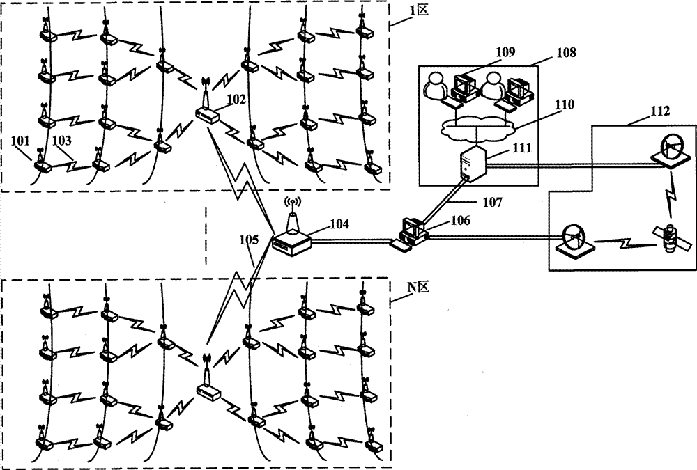
参阅图1,光伏组件排列呈阵列状,对光伏阵列进行区域性划分,将光伏阵列分为N个区,即图1中的1区至N区,形成一个以子区域为单元的分布式网络结构,这样有利于本发明系统取得最大化监测覆盖面积。本发明整个系统包括:多个无线测控器101、至少一无线网关102、一无线收发器104、一本地主控中心106、一异地主控中心108、以及一卫星通信系统112,其中:Referring to Figure 1, the photovoltaic modules are arranged in an array, and the photovoltaic array is divided regionally, and the photovoltaic array is divided into N areas, that is, Area 1 to Area N in Figure 1, forming a distributed network with sub-areas as units. structure, which is beneficial for the system of the present invention to maximize the monitoring coverage area. The whole system of the present invention includes: a plurality of wireless measuring and controlling
无线测控器101用于光伏阵列生存环境、状态信息的数据采集,自主控制光伏组件进行维护与故障预测。一无线测控器101以短程无线通信链路103与相邻的另一无线测控器101实现通信,多个无线测控器101通过短程无线通信链路103与至少一无线网关102实现通信,无线测控器101经过短程无线通信链路103与相邻的无线测控器101交互数据,最终将交互的数据经过短程无线通信链路103传送至无线网关102。The wireless measurement and
至少一无线网关102置于每个子区域中心,可减少子区域内无线网络系统扫描时间。至少一无线网关102通过中程无线通信链路105与子区域外的一无线收发器104通信,无线网关102将本子区域内的所有无线测控器101采集所得的数据经中程无线通信链路105发送至子区域外的无线收发器104。无线网关102在广播信息时,采用功率放大电路,发射范围覆盖子区域全局。At least one
无线收发器104通过接口与一本地主控中心106通信,将所接收的各子区域的无线网关102的数据信息转发至本地主控中心106。The
本地主控中心106,记录和处理整个光伏阵列的实时监测信息,检查所有记录数据的一致性和间隙,识别出明显的异常,直观、清晰的表示每个光伏组件的状态信息。本地主控中心106通过Internet网络107或经卫星通信系统112连接一异地主控中心108,通过Internet网络107或者卫星通信系统112将数据发送至异地主控中心108。异地主控中心108包括主控服务器111、具备联网功能的电子器件109和内部局域网110。当本地有Internet网络107时,本地主控中心106通过Internet网络107将数据发送至异地主控中心108的主控服务器111;当本地无Internet网络107时,本地主控中心106的数据经卫星通信系统112发送至异地主控中心108的主控服务器111,实现数据的远程传输。The local
异地主控中心108通过监视软件和数据库处理与备份全国范围内光伏阵列运行情况,跟踪调查分析单个光伏组件或整体光伏阵列性能。个人计算机、智能手机、PDA等具备联网功能的电子器件109在经过系统允许后通过内部局域网110访问主控服务器111,进行数据查询和命令控制。The remote
参阅图2,无线测控器101和无线网关102包括一嵌入式微控制器201,以及分别外接该嵌入式微控制器201的一供电单元202,一控制单元206,一固定单元209和一检测单元215,其中:Referring to Fig. 2, the wireless measuring and controlling
嵌入式微控制器201,在已知参数的合理范围内针对检测单元215实时采样的数据进行检验,依据数据性质对供电单元202、控制单元206、固定单元209进行相应操作。The embedded
供电单元202提供电源支持,由电源控制电路203、电源管理模块204和备用电池205组成,电源控制电路203的输出分别连接电源管理模块204和备用电池205。电源控制电路203采用双电源切换控制,意外故障造成电源管理模块204断电事故时能及时切换到备用电池205供电。The
控制单元206,包含一光伏组件转动装置控制电路207和一光伏组件清洗系统控制电路208,用于控制光伏组件角度调整和清洗维护,功能模块可扩展,但所扩展功能模块必须有配套数据采集模块提供全方位的数据支持。The
固定单元209,包括时钟芯片210、预留接口211、存储器212、短程无线通信模块213和功率控制模块214。时钟芯片210用于系统时钟同步。预留接口211用于系统功能扩展和无线网关102硬件模块加载。存储器212用于数据存储。短程无线通信模块213实现与邻近的无线测控器101或无线网关102的数据交互。功率控制模块214对发射功率进行硬件限制,其仅在无线网关102中含功率放大电路。The fixed
检测单元215,至少包括一光伏组件电流检测电路216、一光伏组件电压检测电路217、一光伏组件旁路二极管检测电路218和一光伏组件温度传感器219,可扩展添加各类所需传感器或数据采集电路组成一个数据采集协同系统,实现信息的多元采集。The
参阅图3,无线网关102硬件结构加载包括:一太阳光角度检测电路301、一太阳光强度检测电路302、一环境温度传感器303、一风速传感器304一湿度传感器305及中程无线通信模块306,对于子区域内所有无线测控器101提供数据支持;中程无线通信模块306用于无线网关102与无线收发器104之间的数据无线收发。Referring to Fig. 3, the
参阅图4,无线收发器104包括另一个嵌入式微控制器401,以及分别连接该嵌入式微控制器401的另一供电单元402和一固定单元403,其中:Referring to Fig. 4, the
嵌入式微控制器401,用于无线收发器104的数据收发控制。The embedded micro-controller 401 is used to control the data transmission and reception of the
供电单元402,提供电源支持,由另一电源控制电路404、另一电源管理模块405和另一备用电池406组成,另一电源控制电路404的输出分别连接另一电源管理模块405和另一备用电池406。另一电源控制电路404采用双电源切换控制,意外故障造成另一电源管理模块405断电事故时能及时切换到备另一用电池406供电。The
固定单元403,包括存储器407、USB/RS232/RS485接口408、预留接口409和中程无线通信模块306。存储器407用于数据存储,USB/RS232/RS485接口408用于无线收发器104与本地主控中心106通信,预留接口409用于外设扩展,中程无线通信模块306,用于无线网关102与无线收发器104之间的数据无线收发。The fixed
本发明系统的工作步骤为::The working steps of the system of the present invention are:
第一步:无线网络初始化。无线测控器101上电初始化完成后,对自身坐标值进行确定,并对相邻无线测控器101的坐标值及无线网关102所广播的坐标值进行保存,完成网络拓扑构建。Step 1: Wireless network initialization. After the
第二步:数据采集及上传。由于无线网关102含短程无线通信模块213与中程无线通信模块306,因此,能用于子区域内部无线测控器101与无线收发器104之间数据中继。无线测控器101采用短程无线通信方式,监测光伏组件的工作状态,通过短程无线通信链路103和无线网关102实现子区域内部数据交互,交互的数据包括无线测控器101对光伏阵列的自主定位数据,无线网关102对无线测控器101所监测的光伏组件定期进行数据采集,然后通过中程无线通信链路105的中程无线通信方式上传至子区域外部的无线收发器104。无线收发器104采用中程无线通信方式,负责将各子区域内部数据通过USB、RS232等通信方式传递至本地主控中心106,有助于扩大监测区域。数据传递经无线网关102、无线收发器104、本地主控中心106,直至异地主控中心108;The second step: data collection and upload. Since the
第三步:数据分析及命令下发。本地主控中心106及异地主控中心108对所上传的数据进行校验、分析,并依据分析结果对无线测控器101远程控制或对人员进行调配。Step 3: Data analysis and order issuance. The local
无线测控器101在监测光伏组件的工作状态时,具有对光伏阵列自主定位功能,自主定位的方法包括发射半径确定方法、初步定位算法、边界问题处理方法、Y值冲突处理方法,参阅图5,其中,图5(a)为发射半径确定方法原理示意图;图5(b)为初步定位算法、图5(c)为边界问题处理方法原理示意图、图5(d)为Y值冲突处理方法原理示意图。图5中多个无线测控器101呈行列排列,以A、B、C、D、E、F、G、H、I、J、L、M分别表示多个无线测控器101中的某单个无线测控器。When the wireless measurement and
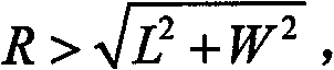
如图5(a)所示,光伏组件在实际应用现场虽呈阵列式排列,在无遮蔽情况下光伏组件排列尽可能紧凑,位于子区域内的两个无线测控器101在不同方向上的间距会存在差异性,采用功率控制模块214将无线测控器101的发射功率进行限制,控制其覆盖范围501。发射半径为其中L为无线测控器101间距较大值,W为无线测控器101间距较小值,保证其邻居无线测控器101数量大于等于8,确保其具备较高的网络连通性。发射半径R<2L,减小网络的冲突域,降低网络的平均竞争强度,有助于减少网络整体能量消耗,提升网络容量。As shown in Figure 5(a), although the photovoltaic modules are arranged in an array in the actual application site, the arrangement of the photovoltaic modules is as compact as possible under the condition of no shelter. There will be differences, and the
见图5(b)所示,依据实际现场子区域内光伏组件所处行列,在子区域内建立直角坐标系,X轴(对应行)为无线测控器101间距相对较大的一侧子区域边沿,Y轴(对应列)为相邻一侧子区域边沿,顶点坐标为(1,1),XY轴上单个无线测控器A坐标点事先设定。所有无线测控器101置于接收状态,无线测控器101的覆盖范围501内已确定坐标点存入邻居表中,其余则存入临时数据表中用作数据处理,待确认坐标点后丢弃临时数据表。依据图5(a)中无线测控器101发射半径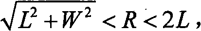
图5(c)是无线测控器101定位算法初步中的边界问题处理。当无线测控器101位于边界(即无线测控器B不存在或暂不可知),图5(b)示X值确认方法已不可行,无线测控器101置于接收状态,覆盖范围501内存在X值相邻、Y值相同的单个无线测控器C、D至少两组,单个无线测控器C仅存在一侧相邻的单个无线测控器D,单个无线测控器D存在左右相邻的另两单个无线测控器C、E,唯一确定无线测控器101所处X值。据此,已最终确定坐标点的无线测控器所发送消息中必须包含其邻居表中是否存在左右相邻无线测控器的说明信息。如果可以确定X值,因数据传播遍历方向,则初步判定Y值为邻居表中一坐标点(X,Ymax)Ymax值加1。待初步判定坐标点后,无线测控器101置发送状态并发送含坐标点的临时信息,后转入接收状态。Fig. 5(c) is the boundary problem processing in the preliminary positioning algorithm of the
图5(d)是无线测控器101定位算法初步中的Y值冲突处理。依图5(b)、图5(c)示Y值初步判定方法,当一组X值相邻、Y值相同的无线测控器503可以初步判定无线测控器F、G具有相同的XY值,即无线测控器F、G的Y值冲突。无线测控器F、G的实际Y值是不同的,即其覆盖范围和邻居表是有差别的。因数据传播遍历方向,两者邻居表中X-1坐标点最先在Y值上表现出差异性。为防边界影响,无线测控器F、G初步判定后所发送的临时信息中应含邻居表中两个单个无线测控器H的坐标点(X-1,Ymax),单个无线测控器I的坐标点(X-1,Ymin)。因数据传播遍历方向和下边界影响,首先比较Ymax,当其Ymax大于所接收到的Ymax时,其Y值加1,小于则Y值不变,如相等则跳转进入Ymin比较,其操作与Ymax比较雷同。如两次比较均相等,则延时等待接收新信息后再次发送临时信息进行比较。如Y值变化,无线测控器F置发送状态并发送临时信息,后转入接收状态。如Y值无变化,则等待规定时间,如在规定时间内其Y值没有冲突,则确定其坐标值并置发送状态发送确定信息。FIG. 5( d ) shows the Y value conflict processing in the preliminary positioning algorithm of the
参阅图6,无线测控器101数据传递规则含:无线网关102位置确定,数据传递主路径确定及发生故障后数据传递路径优选。因无线测控器101本身能耗低且能量充足,网络建立后,无线网关102广播其坐标值,以经过无线网关102并且与X轴平行的直线和与Y轴平行的直线作为数据传递主路径。无线测控器101以无线网关102为最终目的地址发现数据传递路径。数据传递过程中每一跳的目的地址都由这一跳的源地址决定。比较源地址和最终目的地址,从邻居表的中选取靠近最终目的地址一侧且坐标XY值均变化最大的坐标点作为此跳的目的地址,直至最终目的地址。若邻居表中尚未出现最终目的地址,但存在坐标点X值或Y值与最终目的地址X值或Y值一致,则选取靠近最终目的地址一侧且坐标X值或Y值与最终目的地址X值或Y值一致并变化最大的无线测控器J作为这一跳的目的地址,直至最终目的地址。Referring to FIG. 6 , the data transmission rules of the
无线测控器101地址经定位算法确定后固定,单个无线测控器故障不会造成网络拓扑的大规模改变,仅改变经过此无线测控器101的数据传递路径。数据传递采用按需路由,基于目的地址逐跳计算临时路由。如图6,当遇故障点K时仅需单个无线测控器101重新计算路由。当无线测控器101在规定时间内没有收到回复帧,记录故障点K,选择与故障点K坐标X值相同且Y值邻近的无线测控器L作为第一优选目的地址。如第一优选目的地址同样发生故障,则选取邻居表中任一靠近无线网关102的无线测控器M作为目的地址。The address of the
Claims (3)
Priority Applications (1)
| Application Number | Priority Date | Filing Date | Title |
|---|---|---|---|
| CN2010102788938A CN101995862B (en) | 2010-09-10 | 2010-09-10 | Photovoltaic array positioning tracking monitoring system based on internet of things and operating method |
Applications Claiming Priority (1)
| Application Number | Priority Date | Filing Date | Title |
|---|---|---|---|
| CN2010102788938A CN101995862B (en) | 2010-09-10 | 2010-09-10 | Photovoltaic array positioning tracking monitoring system based on internet of things and operating method |
Publications (2)
| Publication Number | Publication Date |
|---|---|
| CN101995862A CN101995862A (en) | 2011-03-30 |
| CN101995862B true CN101995862B (en) | 2012-11-07 |
Family
ID=43786122
Family Applications (1)
| Application Number | Title | Priority Date | Filing Date |
|---|---|---|---|
| CN2010102788938A Expired - Fee Related CN101995862B (en) | 2010-09-10 | 2010-09-10 | Photovoltaic array positioning tracking monitoring system based on internet of things and operating method |
Country Status (1)
| Country | Link |
|---|---|
| CN (1) | CN101995862B (en) |
Families Citing this family (19)
| Publication number | Priority date | Publication date | Assignee | Title |
|---|---|---|---|---|
| CN103197613B (en) * | 2012-01-09 | 2016-03-30 | 中国科学院沈阳自动化研究所 | A kind of photovoltaic power station monitoring system based on industry wireless network |
| CN102541033A (en) * | 2012-02-13 | 2012-07-04 | 无锡泰克塞斯新能源科技有限公司 | Tracking type photovoltaic power generation system capable of preventing disastrous weathers and implementation method thereof |
| CN103581228A (en) * | 2012-07-26 | 2014-02-12 | 深圳市生基科技有限公司 | Method and system for device communication in Internet of Things |
| CN102902248A (en) * | 2012-09-07 | 2013-01-30 | 苏州市职业大学 | Roof photovoltaic power station measurement and control system based on Internet of things (IOT) |
| CN103399580B (en) * | 2013-06-26 | 2016-01-13 | 大连理工大学 | A kind of solar tracking system of internet of things oriented application |
| CN103823927B (en) * | 2014-02-12 | 2016-08-17 | 西安建筑科技大学 | The array arrangement method of tracing type photovoltaic equipment |
| CN103997529B (en) * | 2014-05-24 | 2017-07-14 | 上海新时达电气股份有限公司 | Method, system and the gateway communicated using the gateway with dual identity |
| CN104617872B (en) * | 2015-01-20 | 2018-04-06 | 小米科技有限责任公司 | Solar energy conversion equipment, solar energy conversion method and device |
| CN104868843B (en) * | 2015-06-08 | 2017-05-24 | 江汉大学 | Data processing method for solar photovoltaic module array data collection device |
| CN104868845B (en) * | 2015-06-08 | 2018-08-03 | 江汉大学 | Embedded solar photovoltaic assembly data monitoring device and method |
| CN104868846B (en) * | 2015-06-08 | 2017-10-13 | 江汉大学 | Solar photovoltaic assembly array data acquisition method based on wireless Internet of Things |
| CN105490388B (en) * | 2015-12-31 | 2018-06-19 | 重庆西南集成电路设计有限责任公司 | Photovoltaic plant wireless intelligent monitoring system and method |
| CN105932963B (en) * | 2016-05-12 | 2017-11-28 | 山东华力机电有限公司 | The visual 20000 kilowatts of wisdom power detecting systems of cloud |
| CN106291640A (en) * | 2016-08-22 | 2017-01-04 | 天通精电新科技有限公司 | There is the combined positioning method of spatial positional information and mac address information |
| CN106357220B (en) * | 2016-10-12 | 2018-08-17 | 福州大学 | A kind of distributed photovoltaic string formation and component IV characteristic curve on-line measurement systems |
| CN106712713B (en) * | 2017-03-13 | 2018-01-12 | 广西大学 | The monitoring system and monitoring and abnormal localization method of a kind of photovoltaic plant |
| CN107658976A (en) * | 2017-08-21 | 2018-02-02 | 镇江辉虹电气有限公司 | A kind of new bus warning monitoring system |
| KR101958474B1 (en) * | 2018-11-27 | 2019-03-15 | 주식회사 나눔에너지 | System and method of balancing control for solar photovoltaic generation |
| CN112394319B (en) * | 2019-08-15 | 2025-10-10 | 清研讯科(北京)科技有限公司 | Wireless ranging, direction finding and positioning methods and related equipment |
Citations (3)
| Publication number | Priority date | Publication date | Assignee | Title |
|---|---|---|---|---|
| CN101354577A (en) * | 2008-09-12 | 2009-01-28 | 东南大学 | Remote wireless monitoring method of solar power station |
| CN101674032A (en) * | 2009-10-19 | 2010-03-17 | 浙江大学 | Automatic tracking type photovoltaic power station monitoring system based on wireless network |
| CN101825892A (en) * | 2010-04-26 | 2010-09-08 | 江苏爱康太阳能科技有限公司 | Centralized monitoring system for solar photovoltaic power generation tracking system |
Family Cites Families (1)
| Publication number | Priority date | Publication date | Assignee | Title |
|---|---|---|---|---|
| US8264195B2 (en) * | 2008-10-01 | 2012-09-11 | Paceco Corp. | Network topology for monitoring and controlling a solar panel array |
-
2010
- 2010-09-10 CN CN2010102788938A patent/CN101995862B/en not_active Expired - Fee Related
Patent Citations (3)
| Publication number | Priority date | Publication date | Assignee | Title |
|---|---|---|---|---|
| CN101354577A (en) * | 2008-09-12 | 2009-01-28 | 东南大学 | Remote wireless monitoring method of solar power station |
| CN101674032A (en) * | 2009-10-19 | 2010-03-17 | 浙江大学 | Automatic tracking type photovoltaic power station monitoring system based on wireless network |
| CN101825892A (en) * | 2010-04-26 | 2010-09-08 | 江苏爱康太阳能科技有限公司 | Centralized monitoring system for solar photovoltaic power generation tracking system |
Non-Patent Citations (2)
| Title |
|---|
| 李凌锐等.基于GPRS技术的光伏电站远程监测系统.《太阳能》.2006,(第6期),第27-29页. * |
| 罗存.太阳能分布式发电站远程监控设计.《东北电力技术》.2009,(第8期),第50-52页. * |
Also Published As
| Publication number | Publication date |
|---|---|
| CN101995862A (en) | 2011-03-30 |
Similar Documents
| Publication | Publication Date | Title |
|---|---|---|
| CN101995862B (en) | Photovoltaic array positioning tracking monitoring system based on internet of things and operating method | |
| CN100456188C (en) | Greenhouse variable structure self-organizing wireless sensor network and its construction method | |
| CN102928019A (en) | System and method for monitoring environment based on wireless sensor and geographic information | |
| CN103197613B (en) | A kind of photovoltaic power station monitoring system based on industry wireless network | |
| CN101272330B (en) | Data transmission and positioning system based on wireless sensor network technology | |
| Yong-Min et al. | The architecture and characteristics of wireless sensor network | |
| Song et al. | Design of wireless sensor network-based greenhouse environment monitoring and automatic control system | |
| CN108322187A (en) | Photovoltaic plant monitors and O&M integral system | |
| CN110035468B (en) | High reliability and high security wireless network topology control system | |
| CN109474899A (en) | An automatic monitoring RTU and networking system based on Beidou Cloud IoT | |
| CN103632570A (en) | Wireless transmission method and wireless transmission system | |
| CN111225398B (en) | An energy consumption optimization method for microgrid wireless sensor network based on cooperative coverage | |
| CN102244766A (en) | Remote online monitoring system for wind/solar hybrid power generation equipment | |
| CN101551937B (en) | Mobile wireless environment monitoring system aiming to field cultural relics unearthing site | |
| Costa et al. | Planning and resource allocation of a hybrid IoT network using artificial intelligence | |
| CN101459979B (en) | System networking method based on wireless sensor network | |
| CN109587696B (en) | Method for balancing energy consumption of wireless sensor network in urban comprehensive pipe gallery | |
| CN102573119A (en) | Wireless sensor node for remotely and automatically sampling and measuring air quality | |
| CN110445762A (en) | Intelligent environment protection monitoring management system in highway network based on Internet of Things | |
| CN116634354A (en) | Multi-node communication networking and positioning integrated system and method for underground stations | |
| CN102095890A (en) | Ultrasonic wave wind speed and wind direction measuring device of wind generating set | |
| CN206684585U (en) | Photovoltaic tracking bracket controller small-power multi-hop transmission wireless control system | |
| CN116371855A (en) | Automatic control method of cleaning system of photovoltaic panel cleaning robot | |
| CN207612365U (en) | Unattended field overhead line video monitoring apparatus | |
| CN103697940A (en) | Low-carbon and energy-saving real-time temperature and humidity acquisition system |
Legal Events
| Date | Code | Title | Description |
|---|---|---|---|
| C06 | Publication | ||
| PB01 | Publication | ||
| C10 | Entry into substantive examination | ||
| SE01 | Entry into force of request for substantive examination | ||
| C14 | Grant of patent or utility model | ||
| GR01 | Patent grant | ||
| C41 | Transfer of patent application or patent right or utility model | ||
| TR01 | Transfer of patent right |
Effective date of registration: 20160511 Address after: 212006 No. 666 Mao Mao Road, Yangzhong Economic Development Zone, Jiangsu, Zhenjiang, China Patentee after: Jiangsu Tonglin Electric Co., Ltd. Address before: 212013 Zhenjiang City, Jiangsu Province University Road, No. 301 Patentee before: Jiangsu University |
|
| CF01 | Termination of patent right due to non-payment of annual fee | ||
| CF01 | Termination of patent right due to non-payment of annual fee |
Granted publication date: 20121107 Termination date: 20160910 |