CN101972159A - Six-degree-of-freedom cervical-vertebra grinding parallel robot - Google Patents
Six-degree-of-freedom cervical-vertebra grinding parallel robot Download PDFInfo
- Publication number
- CN101972159A CN101972159A CN 201010557067 CN201010557067A CN101972159A CN 101972159 A CN101972159 A CN 101972159A CN 201010557067 CN201010557067 CN 201010557067 CN 201010557067 A CN201010557067 A CN 201010557067A CN 101972159 A CN101972159 A CN 101972159A
- Authority
- CN
- China
- Prior art keywords
- ball
- side chain
- degree
- abrasive drilling
- grinding
- Prior art date
- Legal status (The legal status is an assumption and is not a legal conclusion. Google has not performed a legal analysis and makes no representation as to the accuracy of the status listed.)
- Granted
Links
Images


Landscapes
- Manipulator (AREA)
Abstract
六自由度颈椎骨磨削并联机器人,它涉及一种磨削并联机器人。本发明为了解决现有的人工颈椎间盘置换手术精度不足、辐射过多、医生工作强度大的问题。本发明的定平台与动平台之间通过三对支链连接,球铰机构设置在滚珠丝杆线性驱动机构的上端,胡克铰机构设置在滚珠丝杆线性驱动机构的下端,球铰机构与动平台连接,胡克铰机构与定平台连接,磨钻电机穿设在动平台内,磨钻电机与磨钻电机连接体固定连接,磨钻电机连接体与动平台固定连接,磨钻体固装在磨钻电机连接体上,磨钻体上设有磨钻顶丝孔,磨钻顶丝孔盖安装在磨钻体的磨钻顶丝孔上,磨钻轴通过联轴器与磨钻电机连接,切削头通过收紧螺母与磨钻轴连接。本发明适用于颈椎骨的磨削。

A six-degree-of-freedom cervical vertebra grinding parallel robot relates to a grinding parallel robot. The invention aims to solve the problems of insufficient accuracy, excessive radiation and high work intensity of doctors in the existing artificial cervical intervertebral disc replacement operation. The fixed platform and the moving platform of the present invention are connected by three pairs of branch chains, the ball hinge mechanism is arranged at the upper end of the ball screw linear drive mechanism, the Hooke hinge mechanism is arranged at the lower end of the ball screw linear drive mechanism, the ball hinge mechanism and the moving platform Connection, the Hooke hinge mechanism is connected with the fixed platform, the grinding and drilling motor is installed in the moving platform, the grinding and drilling motor is fixedly connected with the connecting body of the grinding and drilling motor, the connecting body of the grinding and drilling motor is fixedly connected with the moving platform, and the grinding and drilling body is fixed on the grinding and drilling On the motor connecting body, the drill body is provided with a drill top screw hole, and the drill top screw hole cover is installed on the drill top screw hole of the drill body, and the drill shaft is connected with the drill motor through a coupling, and the cutting The head is connected with the drill shaft through a tightening nut. The invention is suitable for grinding of cervical vertebrae.
Description
技术领域technical field
本发明涉及一种颈椎骨磨削并联机器人,具体涉及一种六自由度颈椎骨磨削并联机器人。The invention relates to a cervical vertebra grinding parallel robot, in particular to a six-degree-of-freedom cervical vertebra grinding parallel robot.
背景技术Background technique
人工颈椎间盘置换手术中的最大难点是需要在正确的位置磨削出与假体吻合的骨关节面,保证假体和人骨的配合,治疗效果严重依赖于手术的精度。目前,人工颈椎间盘置换手术中使用夹具系统来进行磨削定位。这种传统的机械定位系统是基于肉眼对肢体和假体的观察,在手术中广泛使用夹具系统进行打磨、磨削定位,操作繁琐,定位精度主要依赖于医生的经验,这无疑增加了手术的不确定性,影响了假体的安装精度。为了提高手术定位精度,医生经常需要使用X光机反复观察,受射线辐射严重。现有的人工颈椎间盘置换手术精度不足、辐射过多、医生工作强度大。The biggest difficulty in artificial cervical disc replacement surgery is the need to grind the articular surface of the prosthesis in the correct position to ensure the cooperation between the prosthesis and the human bone. The therapeutic effect depends heavily on the accuracy of the operation. Currently, a clamp system is used for grinding positioning in artificial cervical disc replacement surgery. This traditional mechanical positioning system is based on the observation of limbs and prostheses with the naked eye. The fixture system is widely used for grinding and grinding positioning during surgery. Uncertainty affects the installation accuracy of the prosthesis. In order to improve the accuracy of surgical positioning, doctors often need to use X-ray machines for repeated observations, and they are severely exposed to radiation. The existing artificial cervical disc replacement surgery has insufficient precision, excessive radiation, and high workload for doctors.
发明内容Contents of the invention
本发明的目的是为了解决现有的人工颈椎间盘置换手术精度不足、辐射过多、医生工作强度大的问题,进而提供一种六自由度颈椎骨磨削并联机器人。The purpose of the present invention is to solve the problems of insufficient accuracy, excessive radiation, and high work intensity of doctors in the existing artificial cervical disc replacement operation, and further provide a six-degree-of-freedom cervical vertebra grinding parallel robot.
本发明为解决上述技术问题采取的技术方案是:六自由度颈椎骨磨削并联机器人包括定平台、动平台、磨钻和三对支链,定平台与动平台之间通过三对支链连接,每对支链包括两个支链,每个支链均包括球铰机构、滚珠丝杆线性驱动机构和胡克铰机构,球铰机构设置在滚珠丝杆线性驱动机构的上端,胡克铰机构设置在滚珠丝杆线性驱动机构的下端,球铰机构与动平台连接,胡克铰机构与定平台连接,磨钻包括磨钻电机、磨钻电机连接体、联轴器、磨钻顶丝孔盖、磨钻体、轴承端盖、磨钻轴、收紧螺母、切削头和两个第一轴承,磨钻电机穿设在动平台内,磨钻电机与磨钻电机连接体固定连接,磨钻电机连接体与动平台固定连接,磨钻体固装在磨钻电机连接体上,磨钻体上设有磨钻顶丝孔,磨钻顶丝孔盖安装在磨钻体的磨钻顶丝孔上,磨钻轴通过联轴器与磨钻电机连接,磨钻轴与磨钻体之间设有两个第一轴承,第一组轴承通过轴承端盖设置在磨钻体内,切削头通过收紧螺母与磨钻轴连接。The technical solution adopted by the present invention to solve the above-mentioned technical problems is: the six-degree-of-freedom cervical vertebra grinding parallel robot includes a fixed platform, a moving platform, a grinding drill and three pairs of branch chains, and the fixed platform and the moving platform are connected by three pairs of branch chains , each pair of branch chains includes two branch chains, each branch chain includes a ball hinge mechanism, a ball screw linear drive mechanism and a Hooke hinge mechanism, the ball hinge mechanism is set on the upper end of the ball screw linear drive mechanism, and the Hooke hinge mechanism is set on the ball The lower end of the screw linear drive mechanism, the ball hinge mechanism is connected with the moving platform, the Hooke hinge mechanism is connected with the fixed platform, and the grinding drill includes the grinding drill motor, the connecting body of the grinding drill motor, the coupling, the top screw hole cover of the grinding drill, and the grinding drill body , bearing end cover, grinding and drilling shaft, tightening nut, cutting head and two first bearings, the grinding and drilling motor is installed in the moving platform, the grinding and drilling motor is fixedly connected with the connecting body of the grinding and drilling motor, and the connecting body of the grinding and drilling motor is connected with the The moving platform is fixedly connected, the grinding drill body is fixed on the grinding drill motor connecting body, the grinding drill body is provided with a grinding drill top screw hole, and the grinding drill top screw hole cover is installed on the grinding drill top screw hole of the grinding drill body. The drill shaft is connected with the drill motor through a coupling. There are two first bearings between the drill shaft and the drill body. The first set of bearings is set in the drill body through the bearing end cover. The cutting head is connected to the drill body by tightening the nut Grinding drill shaft connection.
本发明的有益效果是:1.本发明是一种医疗用六自由度颈椎骨磨削并联机器人,将并联机器人技术用于在人工颈椎间盘置换手术中,完成人工颈椎间盘置换手术中假体和骨配合面的定位与磨削,取代繁琐的机械定位装置,以此获得精确的假体配合面,提高置换手术精度,并减少了由于人为因素带来的手术风险和并发症。2.本发明实现了假体和骨配合面的定位与磨削,大大降低了医生的工作强度,在X射线检查时,六自由度颈椎骨磨削并联机器人能够代替医生受辐射,减小了医生手术过程中承受的X射线辐射剂量,避免了X光射线对医生造成的伤害,也减少了患者的痛苦,缩短了恢复时间。3.本发明结构紧凑,刚度高,定位精度高,运行平缓,安全性高,承载能力强。可以实现手术最小损伤、提高了疾病诊断和手术治疗的精度与质量。The beneficial effects of the present invention are as follows: 1. The present invention is a medical parallel robot with six degrees of freedom for cervical vertebra grinding, which uses parallel robot technology in artificial cervical intervertebral disc replacement surgery to complete prosthesis and artificial cervical intervertebral disc replacement surgery. The positioning and grinding of the bone mating surface replaces the cumbersome mechanical positioning device, so as to obtain an accurate prosthetic mating surface, improve the accuracy of replacement surgery, and reduce surgical risks and complications caused by human factors. 2. The present invention realizes the positioning and grinding of the prosthesis and the bone mating surface, which greatly reduces the doctor’s work intensity. During X-ray examination, the six-degree-of-freedom cervical vertebra grinding parallel robot can replace the doctor’s exposure to radiation, reducing the The X-ray radiation dose that the doctor receives during the operation avoids the harm caused by the X-ray to the doctor, reduces the pain of the patient, and shortens the recovery time. 3. The present invention has the advantages of compact structure, high rigidity, high positioning accuracy, smooth operation, high safety and strong bearing capacity. It can realize minimal surgical damage and improve the accuracy and quality of disease diagnosis and surgical treatment.
附图说明Description of drawings
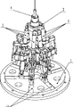
图1是本发明的结构示意图;图2是本发明的俯视图;图3是一个支链3的结构示意图;图4是图3的左视图(拆去定平台1);图5是图3的A-A处的剖视图;图6是图5的B-B处的剖视图;图7是磨钻4的结构示意图;图8是定平台1的结构示意图,图9是动平台2的结构示意图。Fig. 1 is a schematic structural view of the present invention; Fig. 2 is a top view of the present invention; Fig. 3 is a schematic structural view of a
具体实施方式Detailed ways
具体实施方式一:结合图1-图3、图5、图7或图8、图9说明本实施方式,本实施方式的六自由度颈椎骨磨削并联机器人包括定平台1、动平台2、磨钻4和三对支链,定平台1与动平台2之间通过三对支链连接,每对支链包括两个支链3,每个支链3均包括球铰机构3-1、滚珠丝杆线性驱动机构和胡克铰机构3-12,球铰机构3-1设置在滚珠丝杆线性驱动机构的上端,胡克铰机构3-12设置在滚珠丝杆线性驱动机构的下端,球铰机构3-1与动平台2连接,胡克铰机构3-12与定平台1连接,磨钻4包括磨钻电机4-1、磨钻电机连接体4-2、联轴器4-3、磨钻顶丝孔盖4-4、磨钻体4-5、轴承端盖4-6、磨钻轴4-7、收紧螺母4-8、切削头4-9和两个第一轴承4-10,磨钻电机4-1穿设在动平台2内,磨钻电机4-1与磨钻电机连接体4-2固定连接,磨钻电机连接体4-2与动平台2固定连接,磨钻体4-5固装在磨钻电机连接体4-2上,磨钻体4-5上设有磨钻顶丝孔,磨钻顶丝孔盖4-4安装在磨钻体4-5的磨钻顶丝孔上,磨钻轴4-7通过联轴器4-3与磨钻电机4-1连接,磨钻轴4-7与磨钻体4-5之间设有两个第一轴承4-10,第一组轴承4-10通过轴承端盖4-6设置在磨钻体4-5内,切削头4-9通过收紧螺母4-8与磨钻轴4-7连接。Specific Embodiment 1: This embodiment is described in conjunction with Fig. 1-Fig. 3, Fig. 5, Fig. 7 or Fig. 8, Fig. Grinding drill 4 and three pairs of branch chains, the
本发明的机构本体设计采用超硬铝和钢材料。机器人重量≤5Kg,上平台半径:25mm,下平台半径:60mm,高度:200mm;机器人工作空间:线性X向≥30mm、Y向≥10mm、Z向≥30mm,转动X向±5度、Y向±5度;机器人运动分辨率:线性X、Y、Z向优于100μm,转动X、Y向优于1角分;磨削径向承载能力≥50N。6个支链结构完全相同。The design of the mechanism body of the present invention adopts super duralumin and steel materials. Robot weight ≤5Kg, upper platform radius: 25mm, lower platform radius: 60mm, height: 200mm; robot working space: linear X direction ≥ 30mm, Y direction ≥ 10mm, Z direction ≥ 30mm, rotation X direction ± 5 degrees, Y direction ±5 degrees; robot motion resolution: linear X, Y, Z direction is better than 100 μm, rotational X, Y direction is better than 1 arc minute; grinding radial load capacity ≥ 50N. The six branched chain structures are identical.
具体实施方式二:结合图3-图6说明本实施方式,本实施方式的滚珠丝杆线性驱动机构包括支链前伸缩杆3-2、滚珠螺杆3-3、滚珠螺母3-4、轴承端盖3-5、支链电机连接体3-6、轴承隔套3-7、锁紧螺母3-8、支链后杆3-10、支链电机3-11、胡克铰3-12、圆导轨3-13、直线滚珠导套3-14、两个传感器3-15、定位挡块3-16、两个第二轴承3-18,支链电机连接体3-6包括第一连接腔3-6-1和与第一连接腔平行且偏置一定距离的第二连接腔3-6-2,滚珠螺杆3-3的一端穿设在支链前伸缩杆3-2内,滚珠螺杆3-3的一端安装在滚珠螺母3-4内,滚珠螺母3-4固连在支链前伸缩杆3-2上,滚珠螺杆3-3的另一端与支链电机3-11连接,滚珠螺杆3-3的连接端上装有两个第二轴承3-18,两个第二轴承3-18之间通过轴承隔套3-7隔开,并通过锁紧螺母3-8将两个第二轴承3-18固定在滚珠螺杆3-3的输入端上,轴承端盖3-5封装在支链电机连接体3-6上,支链电机连接体3-6的第一连接腔3-6-1套装在第二轴承3-18上,支链电机3-11位于支链后杆3-10内,支链后杆3-10与胡克铰3-12固装,圆导轨3-13设置在支链前伸缩杆3-2上,直线滚珠导套3-14套装在圆导轨3-13上,直线滚珠导套3-14套装在支链电机连接体3-6的第二连接腔3-6-2内,两个传感器3-15固装在支链电机连接体3-6上,定位挡块3-16设置在支链前伸缩杆3-2上,每个支链3的胡克铰3-12的中心沿定平台1呈圆周分布。如此设置,支链电机3-11把运动传递给滚珠螺杆3-3,滚珠螺杆3-3把旋转运动转换成螺母3-4的直线运动,支链前伸缩杆3-2带着圆导轨3-13沿直线滚珠导套3-14进行直线运动,完成了线性驱动的功能。两个光电传感器3-15和定位挡块3-16在六自由度颈椎骨磨削并联机器人的初始化过程中设置增量式编码器的计数零点,在行程范围内设置正、负限位保证机器人的运动安全,两个传感器3-15中一个开关起到限位和设置零位的作用,另一个开关只有限位的作用。其它组成及连接关系与具体实施方式一相同。Specific embodiment two: This embodiment is described in conjunction with Fig. 3-Fig. 6. The ball screw linear drive mechanism of this embodiment includes a branch chain front telescopic rod 3-2, a ball screw 3-3, a ball nut 3-4, and a bearing end Cover 3-5, branch chain motor connector 3-6, bearing spacer 3-7, lock nut 3-8, branch chain rear rod 3-10, branch chain motor 3-11, Hooke hinge 3-12, circular guide rail 3-13, linear ball guide bushing 3-14, two sensors 3-15, positioning block 3-16, two second bearings 3-18, branch chain motor connecting body 3-6 including the first connecting chamber 3- 6-1 and the second connection chamber 3-6-2 parallel to the first connection chamber and offset by a certain distance, one end of the ball screw 3-3 is installed in the front expansion rod 3-2 of the branch chain, and the ball screw 3- One end of 3 is installed in the ball nut 3-4, and the ball nut 3-4 is fixedly connected on the telescopic rod 3-2 before the branch chain, and the other end of the ball screw 3-3 is connected with the branch chain motor 3-11, and the
具体实施方式三:结合图5说明本实施方式,本实施方式的滚珠丝杆线性驱动机构还包括顶丝盖3-9和顶丝3-17,支链电机连接体3-6上设有顶丝孔,顶丝盖3-9设置在顶丝孔上,滚珠螺杆3-3输入端与支链电机3-11的输出轴端之间通过顶丝3-17连接。如此设置,便于顶丝3-18的安装,同时便于顶丝3-18的更换和拧紧。其它组成及连接关系与具体实施方式二相同。Specific Embodiment Three: This embodiment is described in conjunction with FIG. 5. The ball screw linear drive mechanism of this embodiment also includes a jacking screw cover 3-9 and a jacking screw 3-17. The screw hole, the jacking screw cover 3-9 is arranged on the jacking screw hole, and the input end of the ball screw 3-3 is connected with the output shaft end of the branch chain motor 3-11 by a jacking screw 3-17. Such setting facilitates the installation of the top wire 3-18, and facilitates the replacement and tightening of the top wire 3-18. Other components and connections are the same as those in the second embodiment.
具体实施方式四:结合图3-图5说明本实施方式,本实施方式的球铰机构3-1包括球铰钢球体3-1-1和球铰钢球夹持体3-1-2,球铰钢球夹持体3-1-2的连接处安装在支链前伸缩杆3-2上,球铰钢球体3-1-1的钢球在球铰钢球夹持体3-1-2中自由运动。如此设置,球铰钢球体3-1-1的轴线的运动范围是一个以球铰钢球体3-1-1上的球心为顶点的圆锥,有效的满足了每个支链3的活动范围。其它组成及连接关系与具体实施方式一、二或三相同。Specific Embodiment 4: This embodiment is described in conjunction with Fig. 3-Fig. 5. The ball hinge mechanism 3-1 of this embodiment includes a ball hinge steel ball 3-1-1 and a ball hinge steel ball clamping body 3-1-2. The connection of the ball hinge steel ball clamping body 3-1-2 is installed on the front telescopic rod 3-2 of the branch chain, and the steel ball of the ball hinge steel ball 3-1-1 is mounted on the ball hinge steel ball clamping body 3-1. -2 medium free movement. In this way, the movement range of the axis of the ball hinge steel sphere 3-1-1 is a cone with the center of the ball on the ball hinge steel sphere 3-1-1 as the apex, effectively satisfying the movement range of each
具体实施方式五:结合图3-图6说明本实施方式,本实施方式的虎克铰3-12包括上铰链座3-12-1、下铰链座3-12-2、十字顶尖块3-12-3和四个顶针3-12-4,十字顶尖块3-12-3的两对外表面上分别设有锥形顶尖孔,每两个锥形顶尖孔的小径端相对且中心线重合,四个顶针3-12-4分别与上铰链座3-12-1和下铰链座3-12-2的两个侧壁螺纹连接且四个顶针3-12-4分别置于十字顶尖块3-12-3的锥形顶尖孔内,上铰链座3-12-1与支链后杆3-10连接。如此设置,四个顶针3-12-4与十字顶尖块3-12-3形成两个转动副,使得上铰链座3-12-1相对于下铰链座3-12-2沿两个独立的轴进行旋转,实现二维的相对转动。其它组成及连接关系与具体实施方式四相同。Specific embodiment five: This embodiment is described in conjunction with Fig. 3-Fig. 6. The Hooke hinge 3-12 of this embodiment includes an upper hinge seat 3-12-1, a lower hinge seat 3-12-2, a cross top block 3- 12-3 and four thimbles 3-12-4, the two outer surfaces of the cross tip block 3-12-3 are respectively provided with conical tip holes, the small diameter ends of each two conical tip holes are opposite and the center lines coincide, The four thimbles 3-12-4 are threadedly connected with the two side walls of the upper hinge seat 3-12-1 and the lower hinge seat 3-12-2 respectively and the four thimbles 3-12-4 are respectively placed on the
具体实施方式六:结合图2说明本实施方式,本实施方式的所述三对支链,定平台1上胡克铰3-12在360度范围内呈60度间隔均匀分布,动平台2上所述三对球铰链,在360度范围内每对铰链之间的夹角均为30度,每相邻两对铰链之间的夹角均为90度。如此设置,使得机器人具有六个自由度,且结构紧凑,刚度高,定位精度高,运行平缓,安全性高,同时还具有相同工作空间能力时拥有最小的体积,且在工作空间内任何位置均具有给定的承载能力。其它组成及连接关系与具体实施方式一相同。Specific embodiment six: This embodiment is described in conjunction with FIG. 2. For the three pairs of branch chains in this embodiment, the Hooke hinges 3-12 on the
具体实施方式七:结合图3-图9说明本实施方式,本实施方式的定平台1、动平台2、支链前伸缩杆3-2、轴承端盖3-5、支链电机连接体3-6、顶丝空盖3-9、支链后杆3-10、上铰链座3-12-1、下铰链座3-12-2、定位挡块3-16、磨钻电机连接体4-2、磨钻顶丝孔盖4-4、磨钻体4-5和轴承端盖4-6的材料均为铝合金。如此设置,可以减轻六自由度颈椎骨磨削并联机器人的自身重量,同时具有足够的强度,满足了颈椎骨磨削的要求。其它组成及连接关系与具体实施方式一、二、三、五或六相同。Specific Embodiment Seven: This embodiment is described in conjunction with Fig. 3-Fig. -6, top wire empty cover 3-9, branch chain rear rod 3-10, upper hinge seat 3-12-1, lower hinge seat 3-12-2, positioning block 3-16, grinding and drilling motor connector 4 -2, the material of the drill top screw hole cover 4-4, the drill body 4-5 and the bearing end cover 4-6 is aluminum alloy. Such setting can reduce the weight of the parallel robot for cervical vertebra grinding with six degrees of freedom, and at the same time have sufficient strength to meet the requirements of cervical vertebra grinding. The other components and connections are the same as those in
具体实施方式八:结合图1、图2或图8说明本实施方式,本实施方式的定平台1在360度范围内呈60度间隔均匀开有六个圆孔1-2,经过圆孔1-2开设三对定位槽,每个定位槽1-1的中线穿过圆孔1-2的圆心,每对定位槽1-1之间的夹角为30度,每相邻两对定位槽1-1之间的夹角为90度,虎克铰3-12的下铰链座3-12-2通过圆孔1-2安装在定位槽1-1内。如此设置,便于每对支链能够在定平台1上合理分布,使胡克铰的初始转角较小,具有最佳的初始位置,从而提供最大的灵活的运动空间。其它组成及连接关系与具体实施方式一相同。Embodiment 8: This embodiment is described in conjunction with Fig. 1, Fig. 2 or Fig. 8. The fixed
具体实施方式九:结合图1、图2或图9说明本实施方式,本实施方式的动平台2沿径向方向各开设三对圆孔2-3,垂直每个圆孔中心线开设三对外定位平面2-1和三对内定位平面2-2,每对外定位平面2-1之间的夹角为30度,每相邻两对外定位平面2-1之间的夹角为90度,球铰3-1的球铰钢球体3-1-1通过圆孔2-3安装在外定位平面2-1和内定位平面2-2上。如此设置,可以避免结构上的奇异性,同时使得每对支链能够牢固的安装在动平台2上。其它组成及连接关系与具体实施方式一相同。Ninth specific embodiment: This embodiment is described in conjunction with Fig. 1, Fig. 2 or Fig. 9. The moving
具体实施方式十:结合图3或图5说明本实施方式,本实施方式传感器3-15为L型光电传感器。如此设置,在六自由度颈椎骨磨削并联机器人的初始化过程中设置增量式编码器的计数零点,提供一种精确快速机器人零位设置方法,并且保证在行程范围内设置正、负限位,保证机器人的运动安全。其它组成及连接关系与具体实施方式二相同。Embodiment 10: This embodiment is described with reference to FIG. 3 or FIG. 5 . The sensor 3-15 in this embodiment is an L-shaped photoelectric sensor. With this setting, the counting zero point of the incremental encoder is set during the initialization process of the six-degree-of-freedom cervical vertebra grinding parallel robot, providing an accurate and fast method for setting the zero position of the robot, and ensuring that the positive and negative limits are set within the travel range , to ensure the safety of the robot's movement. Other components and connections are the same as those in the second embodiment.
本发明的工作原理是:由医生将六自由度颈椎骨磨削并联机器人安装在可以在手术床上进行上下、左右、前后三个方位可调的支架上,病人躺在手术床上。把三维图像导航技术引入手术之中,通过图像引导和姿态调整确定并联机器人磨钻切削头4-9同病人颈椎骨之间的相对位置,由计算机控制系统把术前的磨削规划轨迹变成驱动脉冲,驱动脉冲对各支链3上的支链电机3-11进行驱动,每个支链3上的支链电机3-11把运动传递给滚珠螺杆3-3,滚珠螺杆3-3把旋转运动转换成螺母3-4的直线伸缩运动(参照图1),支链前伸缩杆3-2带着圆导轨3-13沿直线滚珠导套3-14进行直线上、下运动。两个L型光电传感器3-15在机器人的初始化过程中设置增量式编码器的计数零点,在行程范围内设置正、负限位,以保证机器人的运动安全。每个支链3的线性运动带动动平台2进行相应的运动,动平台2带动磨钻4完成相应的运动轨迹,然后磨钻4的切削头4-9按照规定的轨迹将所需切除的骨骼切除。The working principle of the present invention is as follows: the doctor installs the six-degree-of-freedom cervical vertebra grinding parallel robot on a support that can be adjusted in up and down, left and right, and front and rear directions on the operating bed, and the patient lies on the operating bed. The three-dimensional image navigation technology is introduced into the operation, and the relative position between the grinding, drilling and cutting head 4-9 of the parallel robot and the patient's cervical vertebra is determined through image guidance and posture adjustment, and the preoperative grinding planning trajectory is transformed by the computer control system Driving pulse, the driving pulse drives the branch chain motor 3-11 on each
Claims (10)
Priority Applications (1)
| Application Number | Priority Date | Filing Date | Title |
|---|---|---|---|
| CN201010557067A CN101972159B (en) | 2010-11-24 | 2010-11-24 | Six-degree-of-freedom cervical-vertebra grinding parallel robot |
Applications Claiming Priority (1)
| Application Number | Priority Date | Filing Date | Title |
|---|---|---|---|
| CN201010557067A CN101972159B (en) | 2010-11-24 | 2010-11-24 | Six-degree-of-freedom cervical-vertebra grinding parallel robot |
Publications (2)
| Publication Number | Publication Date |
|---|---|
| CN101972159A true CN101972159A (en) | 2011-02-16 |
| CN101972159B CN101972159B (en) | 2012-09-26 |
Family
ID=43572091
Family Applications (1)
| Application Number | Title | Priority Date | Filing Date |
|---|---|---|---|
| CN201010557067A Expired - Fee Related CN101972159B (en) | 2010-11-24 | 2010-11-24 | Six-degree-of-freedom cervical-vertebra grinding parallel robot |
Country Status (1)
| Country | Link |
|---|---|
| CN (1) | CN101972159B (en) |
Cited By (13)
| Publication number | Priority date | Publication date | Assignee | Title |
|---|---|---|---|---|
| CN102283688A (en) * | 2011-07-27 | 2011-12-21 | 哈尔滨工业大学 | Abrasion drill for robot-assisted cervical disc replacement surgery system |
| CN104323861A (en) * | 2014-11-21 | 2015-02-04 | 山东科技大学 | Three-degree-of-freedom parallel serial joint plastic operation robot |
| CN105662587A (en) * | 2016-04-18 | 2016-06-15 | 山东科技大学 | Orthopaedics operation robot |
| CN106886227A (en) * | 2016-12-26 | 2017-06-23 | 中国科学院长春光学精密机械与物理研究所 | A kind of six degree of freedom high accuracy adjustment alignment system based on 6RRRPRR |
| CN107496004A (en) * | 2017-10-21 | 2017-12-22 | 长沙展朔轩兴信息科技有限公司 | Abrasive drilling for robot-assisted cervical disc replacement surgery system |
| CN109475384A (en) * | 2016-05-25 | 2019-03-15 | 赞克特机器人有限公司 | automatic insertion device |
| CN111227940A (en) * | 2020-01-23 | 2020-06-05 | 诺创智能医疗科技(杭州)有限公司 | Surgical Manipulator and Surgical Robot |
| CN111227944A (en) * | 2020-01-23 | 2020-06-05 | 诺创智能医疗科技(杭州)有限公司 | Operation arm and operation robot |
| US11406397B2 (en) | 2017-11-21 | 2022-08-09 | Qingdao university of technology | Electrostatic atomization ultrasonic aided low-damage and controllable biologic bone grinding process and device |
| US12082893B2 (en) | 2015-11-24 | 2024-09-10 | Think Surgical, Inc. | Robotic pin placement |
| US12161429B2 (en) | 2015-11-24 | 2024-12-10 | Think Surgical, Inc. | Active robotic pin placement in total knee arthroplasty |
| US12178532B2 (en) | 2015-11-24 | 2024-12-31 | Think Surgical, Inc. | Robotic alignment of a tool or pin with a virtual plane |
| US12220137B2 (en) | 2015-11-24 | 2025-02-11 | Think Surgical, Inc. | Cut guide for arthroplasty procedures |
Families Citing this family (1)
| Publication number | Priority date | Publication date | Assignee | Title |
|---|---|---|---|---|
| CN110192920A (en) * | 2019-06-19 | 2019-09-03 | 雅客智慧(北京)科技有限公司 | A kind of operating robot |
Citations (4)
| Publication number | Priority date | Publication date | Assignee | Title |
|---|---|---|---|---|
| WO1999037220A1 (en) * | 1998-01-23 | 1999-07-29 | Sm Scienzia Machinale S.R.L. | Orthopaedic surgery apparatus for guiding a tool and for supporting a limb |
| CN101548904A (en) * | 2009-05-22 | 2009-10-07 | 四川大学 | Robot arm for operation |
| CN101579250A (en) * | 2009-06-18 | 2009-11-18 | 北京科技大学 | Intelligent control device of surgical electric drill |
| WO2010026398A2 (en) * | 2008-09-06 | 2010-03-11 | Comois Orthopaedics Limited | Targeting apparatus |
-
2010
- 2010-11-24 CN CN201010557067A patent/CN101972159B/en not_active Expired - Fee Related
Patent Citations (4)
| Publication number | Priority date | Publication date | Assignee | Title |
|---|---|---|---|---|
| WO1999037220A1 (en) * | 1998-01-23 | 1999-07-29 | Sm Scienzia Machinale S.R.L. | Orthopaedic surgery apparatus for guiding a tool and for supporting a limb |
| WO2010026398A2 (en) * | 2008-09-06 | 2010-03-11 | Comois Orthopaedics Limited | Targeting apparatus |
| CN101548904A (en) * | 2009-05-22 | 2009-10-07 | 四川大学 | Robot arm for operation |
| CN101579250A (en) * | 2009-06-18 | 2009-11-18 | 北京科技大学 | Intelligent control device of surgical electric drill |
Cited By (21)
| Publication number | Priority date | Publication date | Assignee | Title |
|---|---|---|---|---|
| CN102283688A (en) * | 2011-07-27 | 2011-12-21 | 哈尔滨工业大学 | Abrasion drill for robot-assisted cervical disc replacement surgery system |
| CN104323861A (en) * | 2014-11-21 | 2015-02-04 | 山东科技大学 | Three-degree-of-freedom parallel serial joint plastic operation robot |
| CN104323861B (en) * | 2014-11-21 | 2016-08-31 | 山东科技大学 | Three Degree Of Freedom serial-parallel mirror arthroplasty operating robot |
| US12290322B2 (en) | 2015-11-24 | 2025-05-06 | Think Surgical, Inc. | Active robotic pin placement in total knee arthroplasty |
| US12082893B2 (en) | 2015-11-24 | 2024-09-10 | Think Surgical, Inc. | Robotic pin placement |
| US12178532B2 (en) | 2015-11-24 | 2024-12-31 | Think Surgical, Inc. | Robotic alignment of a tool or pin with a virtual plane |
| US12161429B2 (en) | 2015-11-24 | 2024-12-10 | Think Surgical, Inc. | Active robotic pin placement in total knee arthroplasty |
| US12220137B2 (en) | 2015-11-24 | 2025-02-11 | Think Surgical, Inc. | Cut guide for arthroplasty procedures |
| CN105662587A (en) * | 2016-04-18 | 2016-06-15 | 山东科技大学 | Orthopaedics operation robot |
| CN109475384B (en) * | 2016-05-25 | 2022-02-18 | 赞克特机器人有限公司 | Automatic insertion device |
| EP3463142A4 (en) * | 2016-05-25 | 2020-02-26 | Xact Robotics Ltd. | AUTOMATED INTRODUCTION DEVICE |
| US11202684B2 (en) | 2016-05-25 | 2021-12-21 | Xact Robotics Ltd. | Automated insertion device |
| JP2019520183A (en) * | 2016-05-25 | 2019-07-18 | イグザクト ロボティックス リミテッド | Automatic insertion device |
| CN109475384A (en) * | 2016-05-25 | 2019-03-15 | 赞克特机器人有限公司 | automatic insertion device |
| JP7131834B2 (en) | 2016-05-25 | 2022-09-06 | ザクト ロボティクス リミテッド | Automatic insertion device |
| US11751956B2 (en) | 2016-05-25 | 2023-09-12 | Xact Robotics Ltd. | Automated insertion device |
| CN106886227A (en) * | 2016-12-26 | 2017-06-23 | 中国科学院长春光学精密机械与物理研究所 | A kind of six degree of freedom high accuracy adjustment alignment system based on 6RRRPRR |
| CN107496004A (en) * | 2017-10-21 | 2017-12-22 | 长沙展朔轩兴信息科技有限公司 | Abrasive drilling for robot-assisted cervical disc replacement surgery system |
| US11406397B2 (en) | 2017-11-21 | 2022-08-09 | Qingdao university of technology | Electrostatic atomization ultrasonic aided low-damage and controllable biologic bone grinding process and device |
| CN111227944A (en) * | 2020-01-23 | 2020-06-05 | 诺创智能医疗科技(杭州)有限公司 | Operation arm and operation robot |
| CN111227940A (en) * | 2020-01-23 | 2020-06-05 | 诺创智能医疗科技(杭州)有限公司 | Surgical Manipulator and Surgical Robot |
Also Published As
| Publication number | Publication date |
|---|---|
| CN101972159B (en) | 2012-09-26 |
Similar Documents
| Publication | Publication Date | Title |
|---|---|---|
| CN101972159A (en) | Six-degree-of-freedom cervical-vertebra grinding parallel robot | |
| JP7291170B2 (en) | System and method for navigating a pin guide driver | |
| CN112568997B (en) | Direct blade guidance system | |
| CN112568996B (en) | Surgical systems | |
| CN108478266A (en) | Three branch parallel connection Orthopaedic external fixator of free linking | |
| KR102601195B1 (en) | Dental Robots and Method of Oral Navigation | |
| CN110384555A (en) | Videoendoscopic surgery robot is held based on distal center movement mechanism | |
| WO2019140533A1 (en) | Robotic surgical tool | |
| US20250352247A1 (en) | Fracture reduction mechanism for pelvic fracture minimally invasive surgery | |
| CN105662587A (en) | Orthopaedics operation robot | |
| CN109259865B (en) | Intelligent minimally invasive spine surgery robot | |
| CN105916463A (en) | Detachable-mountable arc-shaped precise positioning equipment | |
| CN109998685A (en) | A kind of single, double arm assisted minimally invasive surgical operation robot and cooperative inclusion robot system | |
| CN105496579B (en) | Plant tooth drilling robot based on small cavity | |
| CN104323861B (en) | Three Degree Of Freedom serial-parallel mirror arthroplasty operating robot | |
| CN106175917A (en) | Intersection of sliding perspective orthopaedics pedicle screw inserts auxiliary equipment | |
| CN101933841B (en) | Four degree-of-freedom parallel robot with bipolar coordinate | |
| CN101933840B (en) | Three-drive four degree-of-freedom parallel robot with bipolar coordinate | |
| CN110279469A (en) | A kind of robot | |
| CN101474090A (en) | Six-freedom degree wearing type auxiliary bone-knitting parallel-connected robot | |
| CN114288024B (en) | Systems for robotic-assisted knee arthroplasty | |
| CN206651872U (en) | Spinal movement half restricts formula spinal operation robot | |
| CN105287001A (en) | Robot arm rectoscope system | |
| KR101802486B1 (en) | A grinding machine of grinding temperature online detection and nano-fluid phase change heat transfer type | |
| Ye et al. | Development of a six degree of freedom (DOF) hybrid robot for femur shaft fracture reduction |
Legal Events
| Date | Code | Title | Description |
|---|---|---|---|
| C06 | Publication | ||
| PB01 | Publication | ||
| C10 | Entry into substantive examination | ||
| SE01 | Entry into force of request for substantive examination | ||
| C14 | Grant of patent or utility model | ||
| GR01 | Patent grant | ||
| CF01 | Termination of patent right due to non-payment of annual fee |
Granted publication date: 20120926 Termination date: 20211124 |
|
| CF01 | Termination of patent right due to non-payment of annual fee |