CN101971612B - Image processing device and method - Google Patents
Image processing device and method Download PDFInfo
- Publication number
- CN101971612B CN101971612B CN2008801256681A CN200880125668A CN101971612B CN 101971612 B CN101971612 B CN 101971612B CN 2008801256681 A CN2008801256681 A CN 2008801256681A CN 200880125668 A CN200880125668 A CN 200880125668A CN 101971612 B CN101971612 B CN 101971612B
- Authority
- CN
- China
- Prior art keywords
- image
- value
- signal
- gain
- section
- Prior art date
- Legal status (The legal status is an assumption and is not a legal conclusion. Google has not performed a legal analysis and makes no representation as to the accuracy of the status listed.)
- Expired - Fee Related
Links
Images


Classifications
-
- G—PHYSICS
- G06—COMPUTING OR CALCULATING; COUNTING
- G06T—IMAGE DATA PROCESSING OR GENERATION, IN GENERAL
- G06T5/00—Image enhancement or restoration
- G06T5/90—Dynamic range modification of images or parts thereof
- G06T5/94—Dynamic range modification of images or parts thereof based on local image properties, e.g. for local contrast enhancement
-
- G—PHYSICS
- G06—COMPUTING OR CALCULATING; COUNTING
- G06T—IMAGE DATA PROCESSING OR GENERATION, IN GENERAL
- G06T5/00—Image enhancement or restoration
- G06T5/20—Image enhancement or restoration using local operators
-
- G—PHYSICS
- G06—COMPUTING OR CALCULATING; COUNTING
- G06T—IMAGE DATA PROCESSING OR GENERATION, IN GENERAL
- G06T5/00—Image enhancement or restoration
- G06T5/40—Image enhancement or restoration using histogram techniques
-
- G—PHYSICS
- G06—COMPUTING OR CALCULATING; COUNTING
- G06T—IMAGE DATA PROCESSING OR GENERATION, IN GENERAL
- G06T5/00—Image enhancement or restoration
- G06T5/70—Denoising; Smoothing
-
- G—PHYSICS
- G06—COMPUTING OR CALCULATING; COUNTING
- G06T—IMAGE DATA PROCESSING OR GENERATION, IN GENERAL
- G06T7/00—Image analysis
- G06T7/10—Segmentation; Edge detection
- G06T7/136—Segmentation; Edge detection involving thresholding
-
- H—ELECTRICITY
- H04—ELECTRIC COMMUNICATION TECHNIQUE
- H04N—PICTORIAL COMMUNICATION, e.g. TELEVISION
- H04N1/00—Scanning, transmission or reproduction of documents or the like, e.g. facsimile transmission; Details thereof
- H04N1/40—Picture signal circuits
- H04N1/407—Control or modification of tonal gradation or of extreme levels, e.g. background level
- H04N1/4072—Control or modification of tonal gradation or of extreme levels, e.g. background level dependent on the contents of the original
-
- H—ELECTRICITY
- H04—ELECTRIC COMMUNICATION TECHNIQUE
- H04N—PICTORIAL COMMUNICATION, e.g. TELEVISION
- H04N1/00—Scanning, transmission or reproduction of documents or the like, e.g. facsimile transmission; Details thereof
- H04N1/40—Picture signal circuits
- H04N1/409—Edge or detail enhancement; Noise or error suppression
- H04N1/4092—Edge or detail enhancement
-
- H—ELECTRICITY
- H04—ELECTRIC COMMUNICATION TECHNIQUE
- H04N—PICTORIAL COMMUNICATION, e.g. TELEVISION
- H04N21/00—Selective content distribution, e.g. interactive television or video on demand [VOD]
- H04N21/40—Client devices specifically adapted for the reception of or interaction with content, e.g. set-top-box [STB]; Operations thereof
- H04N21/43—Processing of content or additional data, e.g. demultiplexing additional data from a digital video stream; Elementary client operations, e.g. monitoring of home network or synchronising decoder's clock; Client middleware
- H04N21/44—Processing of video elementary streams, e.g. splicing a video clip retrieved from local storage with an incoming video stream or rendering scenes according to encoded video stream scene graphs
- H04N21/44008—Processing of video elementary streams, e.g. splicing a video clip retrieved from local storage with an incoming video stream or rendering scenes according to encoded video stream scene graphs involving operations for analysing video streams, e.g. detecting features or characteristics in the video stream
-
- H—ELECTRICITY
- H04—ELECTRIC COMMUNICATION TECHNIQUE
- H04N—PICTORIAL COMMUNICATION, e.g. TELEVISION
- H04N23/00—Cameras or camera modules comprising electronic image sensors; Control thereof
- H04N23/70—Circuitry for compensating brightness variation in the scene
- H04N23/76—Circuitry for compensating brightness variation in the scene by influencing the image signals
-
- H—ELECTRICITY
- H04—ELECTRIC COMMUNICATION TECHNIQUE
- H04N—PICTORIAL COMMUNICATION, e.g. TELEVISION
- H04N5/00—Details of television systems
- H04N5/14—Picture signal circuitry for video frequency region
- H04N5/142—Edging; Contouring
-
- H—ELECTRICITY
- H04—ELECTRIC COMMUNICATION TECHNIQUE
- H04N—PICTORIAL COMMUNICATION, e.g. TELEVISION
- H04N5/00—Details of television systems
- H04N5/14—Picture signal circuitry for video frequency region
- H04N5/21—Circuitry for suppressing or minimising disturbance, e.g. moiré or halo
-
- H—ELECTRICITY
- H04—ELECTRIC COMMUNICATION TECHNIQUE
- H04N—PICTORIAL COMMUNICATION, e.g. TELEVISION
- H04N5/00—Details of television systems
- H04N5/44—Receiver circuitry for the reception of television signals according to analogue transmission standards
- H04N5/57—Control of contrast or brightness
-
- G—PHYSICS
- G06—COMPUTING OR CALCULATING; COUNTING
- G06T—IMAGE DATA PROCESSING OR GENERATION, IN GENERAL
- G06T2200/00—Indexing scheme for image data processing or generation, in general
- G06T2200/21—Indexing scheme for image data processing or generation, in general involving computational photography
-
- G—PHYSICS
- G06—COMPUTING OR CALCULATING; COUNTING
- G06T—IMAGE DATA PROCESSING OR GENERATION, IN GENERAL
- G06T2207/00—Indexing scheme for image analysis or image enhancement
- G06T2207/20—Special algorithmic details
- G06T2207/20172—Image enhancement details
- G06T2207/20192—Edge enhancement; Edge preservation
Landscapes
- Engineering & Computer Science (AREA)
- Multimedia (AREA)
- Signal Processing (AREA)
- Physics & Mathematics (AREA)
- General Physics & Mathematics (AREA)
- Theoretical Computer Science (AREA)
- Computer Vision & Pattern Recognition (AREA)
- Image Processing (AREA)
- Picture Signal Circuits (AREA)
- Studio Devices (AREA)
Abstract
Description
技术领域 technical field
本发明涉及图像处理装置和方法、程序和记录介质,并且更具体地,涉及用于实现能够使用简单配置抑制图像质量恶化的灰度(grayscale)压缩的图像处理装置和方法、程序和记录介质。 The present invention relates to an image processing device and method, a program, and a recording medium, and more particularly, to an image processing device and method, a program, and a recording medium for realizing grayscale compression capable of suppressing deterioration of image quality with a simple configuration. the
背景技术Background technique
例如,使用诸如CCD的成像元件的传统相机在背光条件下成像期间,由于它们与使用光学胶卷的相机相比较窄的动态范围,容易过曝光或曝光不足。过曝光导致亮区的灰度损失,而曝光不足导致暗区的灰度损失。然而,固态成像元件(更低噪声)和包围(bracket)曝光合成技术的新近进展使得可以获得能与光学胶卷照片相比的具有宽动态范围的亮度灰度的RAW图像信号。 For example, conventional cameras using imaging elements such as CCDs are prone to overexposure or underexposure during imaging under backlight conditions due to their narrower dynamic range compared to cameras using optical film. Overexposure results in a loss of gray in bright areas, while underexposure results in a loss of gray in dark areas. However, recent advances in solid-state imaging elements (lower noise) and bracket exposure synthesis technology have made it possible to obtain RAW image signals having a wide dynamic range of luminance gradations comparable to optical film photographs. the
另一方面,用来存储所捕捉的运动和静止图像的文件格式(例如,JPEG和MPEG)以及诸如CRT、LCD和打印机的一般显示装置即使在今天在能被表达的亮度灰度级方面也具有局限。即,能由显示装置表达的图像的动态范围较窄。因而,即使获得了能与光学胶卷照片相比的具有宽动态范围的亮度灰度级的RAW图像信号(下文中,称为宽动态范围图像),也不能存储或表达(例如,显示或打印)图像。应注意,RAW图像信号是所谓成像器输出信号。 On the other hand, file formats (e.g., JPEG and MPEG) used to store captured moving and still images, and general display devices such as CRTs, LCDs, and printers have limitations in the gray scales of brightness that can be expressed even today. limited. That is, the dynamic range of images that can be expressed by the display device is narrow. Thus, even if a RAW image signal (hereinafter, referred to as a wide dynamic range image) of brightness grayscales having a wide dynamic range comparable to optical film photographs is obtained, it cannot be stored or expressed (for example, displayed or printed) image. It should be noted that the RAW image signal is a so-called imager output signal. the
因此,需要一种动态范围压缩技术,该技术将宽动态范围图像的亮度灰度级压缩为较窄的动态范围以便将宽动态范围图像转换为能由显示装置和其他传统设备表达的图像(下文中,称为窄动态范围图像)。 Therefore, there is a need for a dynamic range compression technique that compresses the brightness grayscale of a wide dynamic range image into a narrower dynamic range so as to convert the wide dynamic range image into an image that can be expressed by display devices and other conventional devices (below Herein, it is called a narrow dynamic range image). the
例如,可采用基于宽动态范围图像的亮度直方图以可适应的方式确定灰度级的重新分布的技术(参照专利文档1)。例如,该技术将宽动态范围图像的灰度级变换为直方图,由此根据具有较窄动态范围并生成窄动态范围图像的显示装置或其他设备来重新分布灰度级。另外,该技术确定灰度转换曲线,通过该曲线,靠近直方图峰值的亮度值被分配给尽可能多的灰度级,由此抑制基本主体(subject)对比度的下降。被设计为响应于输入图像亮度以全域(across-the-board)方式确定输出亮度的方法如同该技术一样被称为全局灰度压缩技术。 For example, a technique of determining redistribution of gray levels in an adaptive manner based on a brightness histogram of a wide dynamic range image (refer to Patent Document 1) may be employed. For example, this technique transforms the gray levels of a wide dynamic range image into a histogram, thereby redistributing the gray levels according to a display device or other device that has a narrower dynamic range and generates the narrow dynamic range image. In addition, this technique determines a grayscale conversion curve by which luminance values near the peak of the histogram are assigned to as many grayscale levels as possible, thereby suppressing a drop in basic subject contrast. A method designed to determine output luminance across-the-board in response to input image luminance is called a global grayscale compression technique as this technique. the
然而,全局灰度压缩技术导致灰度转换曲线的导数较小的亮度级(灰度范围减少的亮度级)上的小的亮度变化,产生乏味的图像,缺乏小幅对比度和主体的三维表现(下文中,将统称为纹理或细节感觉)。 However, global grayscale compression techniques lead to small brightness changes at luminance levels where the derivative of the grayscale transfer curve is small (luminance levels with reduced grayscale range), producing dull images that lack small contrast and three-dimensional representation of the subject (below In this paper, it will be collectively referred to as texture or detail sense). the
结果,局部灰度压缩技术可用作解决伴随着全局灰度压缩技术的弱表现问题的灰度压缩技术。该技术基于具有大动态范围的图像通常由于高对比度发光而非主体自己的对比度而产生这一知识,通过仅仅压缩发光分量的灰度级,缩窄动态范围。该技术不响应于输入图像亮度以全域方式确定输出亮度,而相反,输入亮度和输出亮度之间的关系随着像素变化。这是该技术与全局灰度压缩技术相比被称为局部压缩技术的原因。 As a result, the local grayscale compression technique can be used as a grayscale compression technique that solves the problem of weak representation accompanying the global grayscale compression technique. This technique narrows the dynamic range by compressing only the gray levels of the luminescence component, based on the knowledge that images with a large dynamic range are usually produced due to high-contrast luminescence rather than the subject's own contrast. This technique does not globally determine output luminance in response to input image luminance, but rather, the relationship between input luminance and output luminance varies pixel by pixel. This is why this technique is called a local compression technique compared to a global grayscale compression technique. the
在使用局部灰度压缩技术的技术中,有适合于在借助于全局灰度压缩技术暂时进行图像的灰度压缩之后补偿除了发光分量之外的分量的技术(例如,参照专利文档2)。除了上述以外,公开了另一技术,例如,在文档:Z.Rahman、D.J.Jobson和G.A.Woodell“Multi-Scale Retinex for Color Image Enhancement”Proc.of International Conference on Image Processing 1996,1996,pp.19P9中。该技术将宽动态范围图像分为多个频率分量图像,使得这些图像进行彼此不同的幅值调制,并将这些图像叠加和组合为单个图像。 Among techniques using the local grayscale compression technique, there is a technique suitable for compensating components other than the luminescence component after temporarily performing grayscale compression of an image by means of the global grayscale compression technique (for example, refer to Patent Document 2). In addition to the above, another technique is disclosed, for example, in the document: Z. Rahman, D.J. Jobson and G.A. Woodell "Multi-Scale Retinex for Color Image Enhancement" Proc. of International Conference on Image Processing 1996, 1996, pp.19P9 . This technique divides a wide dynamic range image into multiple frequency component images such that these images are amplitude modulated differently from each other, and superimposes and combines these images into a single image. the
这些技术使用低通滤波器将图像分为频带,并基于公共发光分布在除了边缘以外的区域中轻缓地倾斜的特性,将低频图像分量处理为发光分量。 These techniques divide an image into frequency bands using a low-pass filter, and process low-frequency image components as luminescence components based on the characteristic that the common luminescence distribution is gently sloped in regions other than the edges. the
专利文档1:日本专利特开平9-331469 Patent Document 1: Japanese Patent Laid-Open No. 9-331469
专利文档2:日本专利特开No.2004-221644 Patent Document 2: Japanese Patent Laid-Open No.2004-221644
发明内容 Contents of the invention
技术问题 technical problem
然而,仅仅使用低通滤波器将图像简单地分为频带,可能导致发光分量边缘处的低分离准确度,导致沿着主体轮廓的灰度倒置,并导致图像质量恶化。因为该倒置类似光环(halo),所以这种恶化被称为光环假象(或简称为光环)。 However, simply dividing the image into frequency bands using only a low-pass filter can lead to low separation accuracy at the edges of the luminescence component, lead to grayscale inversion along the subject contour, and lead to image quality degradation. Because this inversion resembles a halo, this deterioration is called halo artifact (or simply halo). the
为了解决这种光环假象,公开了局部灰度压缩技术,例如,在文档: F.Durand和J.Dorsey,“Fast bilateral filtering for the display of High-dynamic-range images”Proc.SIGGRAPH 02,pp.257-266,2002和文档:R.Sobol,“Improving the Retinex algorithm for rendering wide dynamic range photographs”,Journal of Electronic Imaging,Vol.13(1),pp.65-74,2004。该技术使用边缘保留非线性低通滤波器(双边滤波器)分离发光分量。然而,对于非线性过滤的计算代价过高以及由于缺少确定在过滤器的边缘确定时使用的阈值的方针而不能自动调整阈值参数的实现方式,即使这些技术也仍然有问题。 To address this halo artifact, local grayscale compression techniques are disclosed, e.g., in the document: F. Durand and J. Dorsey, "Fast bilateral filtering for the display of High-dynamic-range images" Proc.SIGGRAPH 02, pp. 257-266, 2002 and Documentation: R. Sobol, "Improving the Retinex algorithm for rendering wide dynamic range photographs", Journal of Electronic Imaging, Vol.13(1), pp.65-74, 2004. This technique uses an edge-preserving nonlinear low-pass filter (a bilateral filter) to separate the luminescent component. However, even these techniques remain problematic for implementations where non-linear filtering is computationally prohibitively expensive and cannot automatically adjust the threshold parameter due to lack of guidelines for determining the threshold used in filter edge determination. the
另外,当对彩色图像进行灰度压缩时,产生彩色图像所特有的问题。这些问题包括在灰度压缩之后部分彩色灰度的损失,其结果是图像看起来单调,色彩偏离以及某些不自然的色彩。 In addition, when grayscale compression is performed on a color image, problems unique to color images arise. These problems include the loss of some color grayscale after grayscale compression, and the result is that the image looks flat, with color deviation and some unnatural colors. the
当亮度的灰度压缩结果反映到输入彩色图像上时,由RGB信号的饱和引起由于彩色灰度的部分损失带来的单调图像。色彩偏离也是由信号饱和引起的。三个RGB频道信号之一的饱和引起不平衡的RGB,导致色彩偏离。 When the grayscale compression result of brightness is reflected on the input color image, the saturation of the RGB signal causes a monotonous image due to the partial loss of the color grayscale. Color shift is also caused by signal saturation. Saturation of one of the three RGB channel signals causes unbalanced RGB, resulting in color shifting. the
为此,由以下文档提出的技术非线性地调制RGB信号,以便调整灰度压缩算法中的饱和度:L.Wang、T.Horiuchi和H.Kotera,“HDR Image Compression based on Local Adaptation for Scene and Display Using Retinal Model”,Proc.14th Color Imaging Conference,pp.327-332,2006。该技术有利之处在于它能使用简单的数学表达式调整饱和度,但是不利之处在于作为色域压缩它提供差的性能,并且具有低的调整自由度。非线性调制可能导致不平衡的RGB,由此导致不自然的色彩或者输出装置的色域的不合适的校正。 To this end, the technique proposed by the following document nonlinearly modulates the RGB signal in order to adjust the saturation in the grayscale compression algorithm: L. Wang, T. Horiuchi and H. Kotera, "HDR Image Compression based on Local Adaptation for Scene and Display Using Retinal Model”, Proc.14th Color Imaging Conference, pp.327-332, 2006. This technique is advantageous in that it can adjust saturation using a simple mathematical expression, but disadvantageous in that it provides poor performance as a gamut compression and has low adjustment freedom. Non-linear modulation may result in unbalanced RGB, thereby causing unnatural colors or improper correction of the color gamut of the output device.
另外,彩色图像的压缩导致高色度区域的不自然的辉度(brightness)。该问题由于以下事实引起:当使用亮度信号估计发光的辉度时,该估计在高色度区域有大误差,结果,该区域的辉度被估计为比它真实情况更暗。 Additionally, compression of color images results in unnatural brightness in high chrominance areas. This problem arises from the fact that when luminance signals are used to estimate the luminance of luminescence, the estimation has a large error in high chroma regions, and as a result, the luminance of this region is estimated to be darker than it really is. the
再者,上述灰度压缩技术隐含假设一种理想系统,其中动态范围足够大。因而,如果任何上述技术被合并到相机信号处理中进行操作,则由于输入信号或信号处理局限而产生问题。 Furthermore, the above grayscale compression techniques implicitly assume an ideal system in which the dynamic range is sufficiently large. Thus, if any of the above techniques are incorporated into camera signal processing to operate, problems arise due to input signal or signal processing limitations. the
问题之一是由于成像元件的饱和引起的图像质量故障。无论成像元件中饱和的区域在灰度上压缩(在亮度上抑制)得有多好,该区域的灰度不会变明显。如果有的话,则图像的白点变得更暗,导致图像质量恶化。另外,在 颜色传感器的某些颜色饱和的区域中,作为灰度压缩的结果,除了主体的颜色之外的颜色可能突出自己,导致图像质量恶化。 One of the problems is image quality failure due to saturation of imaging elements. No matter how well a saturated area in an imaging element is compressed in gray (suppressed in brightness), the gray in that area will not become noticeable. If anything, the white point of the image becomes darker, causing image quality to deteriorate. Also, in certain color-saturated areas of the color sensor, as a result of grayscale compression, colors other than the subject's color may stand out by themselves, causing image quality to deteriorate. the
另一问题是由于缺少与相机信号处理参数的协调而引起的图像质量恶化。在相机信号处理中,当开发RAW信号时,通过调整高亮度区域中的灰度曲线,初始地执行更多或更少的全局灰度压缩。根据全局灰度压缩确定成像曝光。如果这里增加了不同的灰度压缩,则成像曝光设置和灰度曲线之间的关系被打乱,阻碍了如所期望那样的进行开发。除了上述以外,由于灰度压缩引起的噪声增加,噪声减少不如预期的那样有效,导致噪声的更差的感觉。 Another problem is image quality degradation due to lack of coordination with camera signal processing parameters. In camera signal processing, when developing a RAW signal, more or less global grayscale compression is initially performed by adjusting the grayscale curve in high brightness areas. Determine imaging exposure based on global grayscale compression. If different grayscale compressions were added here, the relationship between imaging exposure settings and grayscale curves would be disrupted, preventing development as desired. In addition to the above, noise reduction is not as effective as expected due to the noise increase caused by grayscale compression, resulting in a worse perception of noise. the
另外,尽管已经提出了许多局部灰度压缩技术,但所有这些技术中发光分量的压缩技术由给定算法定义。这导致在应用于相机信号处理时图像质量设置的自由度较低。 In addition, although many local grayscale compression techniques have been proposed, the compression technique of the luminescence component in all these techniques is defined by a given algorithm. This results in less freedom of image quality setting when applied to camera signal processing. the
鉴于上文,本发明的一个目的是实现能够使用简单的配置抑制图像质量恶化的灰度压缩。 In view of the above, an object of the present invention is to realize gradation compression capable of suppressing deterioration of image quality with a simple configuration. the
技术方案 Technical solutions
本发明的一个方面是图像处理装置。该成像处理装置包括边缘保留低通滤波器、平均亮度计算部件和阈值计算部件。边缘保留低通滤波器基于对要处理的目标像素确定的参考像素值和阈值,确定输入图像中与要处理的目标像素临近的每个像素是否有效。然后,边缘保留低通滤波器使用已经被确定为有效的临近像素的值进行平滑。平均亮度计算部件基于输入图像的亮度分布将输入图像划分为多个区域,以计算每个区域的平均亮度值。阈值计算部件基于由平均亮度计算部件计算的每个区域的平均亮度值,计算要在边缘保留低通滤波器中设置的阈值。 One aspect of the present invention is an image processing device. The imaging processing device includes an edge-preserving low-pass filter, an average brightness calculation unit, and a threshold value calculation unit. The edge-preserving low-pass filter determines whether each pixel in the input image adjacent to the target pixel to be processed is valid based on a reference pixel value determined for the target pixel to be processed and a threshold value. An edge-preserving low-pass filter is then smoothed using the values of neighboring pixels that have been determined to be valid. The average luminance calculation section divides the input image into a plurality of regions based on the luminance distribution of the input image to calculate an average luminance value for each region. The threshold calculation section calculates a threshold to be set in the edge-preserving low-pass filter based on the average luminance value of each area calculated by the average luminance calculation section. the
阈值计算部件可通过将平均亮度值(每个区域一个)之间的绝对差乘以预定固定值而计算阈值。 The threshold calculation section may calculate the threshold by multiplying the absolute difference between the average luminance values (one for each area) by a predetermined fixed value. the
成像处理装置还可包括提取部件、标识部件和细节分量校正部件。提取部件使用边缘保留低通滤波器从输入图像中提取具有发光信号的大幅值周期的发光分量,以提取细节分量作为输入图像的亮度信号和发光分量之间的差。标识部件标识被确定为与发光分量相称的增益。细节分量校正部件将细节分量乘以由标识部件标识的增益,以校正细节分量。 The imaging processing device may further include extraction means, identification means, and detail component correction means. The extracting section extracts a luminescence component having a large-value period of the luminescence signal from the input image using an edge-preserving low-pass filter to extract a detail component as a difference between the luminance signal and the luminescence component of the input image. The identification means identifies a gain determined to be commensurate with the luminescence component. The detail component correcting section multiplies the detail component by the gain identified by the identifying section to correct the detail component. the
标识部件可基于增益特性标识与图像的亮度值相关联的多个区域中的 每一个。基于完全自适应增益获得增益特性。通过基于每个区域的平均亮度值的算术运算找到的完全自适应增益是用于完全自适应的乘数(multiplier)。 The identifying component can identify each of the plurality of regions associated with a brightness value of the image based on the gain characteristic. Gain characteristics are obtained based on fully adaptive gains. The full adaptation gain found by arithmetic operation based on the average luminance value of each region is a multiplier for full adaptation. the
标识部件可基于增益特性标识与图像的亮度值相关联的多个区域中的每一个。基于校正增益获得增益特性。通过对完全自适应增益进行预定算术运算而找到校正增益。基于每个区域的平均亮度值的算术运算而找到的完全自适应增益是用于完全自适应的乘数。 The identifying component can identify each of the plurality of regions associated with a brightness value of the image based on the gain characteristic. A gain characteristic is obtained based on the correction gain. The correction gain is found by performing a predetermined arithmetic operation on the fully adaptive gain. The full adaptation gain, which is found based on the arithmetic operation of the average luminance value of each region, is a multiplier for full adaptation. the
在适用于找到校正增益的算术运算中,可使用自适应级。基于根据动态范围值确定的预设自适应级特性标识自适应级。基于与图像的亮度值相关联的多个区域中的每一个的平均亮度值计算动态范围值。 In the arithmetic operation applied to find the correction gain, an adaptive stage can be used. An adaptation level is identified based on preset adaptation level characteristics determined from the dynamic range value. A dynamic range value is calculated based on an average luminance value for each of a plurality of regions associated with luminance values of the image. the
标识部件可通过设置第一值为校正增益的上限并设置第二值为校正增益的下限而确定增益特性。第一值通过基于自适应级校正与所有多个区域中最暗的区域相关联的完全自适应增益而获得。第二值通过基于自适应级校正与所有多个区域中最亮的区域相关联的完全自适应增益而获得。 The identification means may determine the gain characteristic by setting the first value as an upper limit of the correction gain and setting the second value as a lower limit of the correction gain. The first value is obtained by correcting the full adaptive gain associated with the darkest region of all the plurality of regions based on the adaptive level. The second value is obtained by correcting the full adaptive gain associated with the brightest region of all the plurality of regions based on the adaptive level. the
成像处理装置还可包括稀疏部件和增加部件。稀疏部件稀疏化输入图像中的像素数目。增加部件将已经被稀疏部件稀疏了像素的图像的像素数目增加为原始数目。已经被稀疏部件稀疏了像素的图像被馈送到边缘保留低通滤波器。与从边缘保留低通滤波器输出的信号相关联的图像被馈送到增加部件。 The imaging processing device may further include a thinning component and an augmenting component. The sparse component thins out the number of pixels in the input image. The increasing means increases the number of pixels of the image whose pixels have been thinned out by the thinning means to the original number. The image that has been thinned out by the thinning component is fed to an edge preserving low pass filter. The image associated with the signal output from the edge-preserving low-pass filter is fed to an augmentation component. the
本发明的另一方面是图像处理方法。该图像处理方法包括基于对要处理的目标像素确定的参考像素值和阈值确定输入图像中与要处理的目标像素临近的每个像素是否有效的步骤。该图像处理方法还包括使用已经被确定为有效的临近像素的值进行平滑的步骤。该图像处理方法还包括基于输入图像的亮度分布将输入图像划分为多个区域以计算每个区域的平均亮度值的步骤。该图像处理方法还包括基于每个区域的平均亮度值算阈值的步骤。 Another aspect of the invention is an image processing method. The image processing method includes the step of determining whether each pixel in the input image adjacent to the target pixel to be processed is valid based on a reference pixel value determined for the target pixel to be processed and a threshold value. The image processing method also includes the step of smoothing using values of neighboring pixels that have been determined to be valid. The image processing method further includes the step of dividing the input image into a plurality of regions based on the brightness distribution of the input image to calculate an average brightness value of each region. The image processing method also includes a step of calculating a threshold based on the average brightness value of each region. the
本发明的再一方面是用于使得计算机执行图像处理的程序。该图像处理包括基于对要处理的目标像素确定的参考像素值和阈值确定输入图像中与要处理的目标像素临近的每个像素是否有效的步骤。该图像处理还包括使用已经被确定为有效的临近像素的值进行平滑的步骤。该图像处理还包括基于输入图像的亮度分布将输入图像划分为多个区域以计算每个区域的平均亮度值的步骤。该图像处理还包括基于每个区域的平均亮度值算阈值的步骤。 Still another aspect of the present invention is a program for causing a computer to execute image processing. The image processing includes the step of determining whether each pixel in the input image adjacent to the target pixel to be processed is valid based on the reference pixel value determined for the target pixel to be processed and a threshold value. The image processing also includes a smoothing step using the values of neighboring pixels that have been determined to be valid. The image processing also includes the step of dividing the input image into a plurality of regions based on the brightness distribution of the input image to calculate an average brightness value for each region. The image processing also includes a step of calculating a threshold based on the average brightness value of each region. the
本发明的再一方面是记录介质,该记录介质上记录程序。该程序使得计 算机执行图像处理。该图像处理方法包括基于对要处理的目标像素确定的参考像素值和阈值确定输入图像中与要处理的目标像素临近的每个像素是否有效的步骤。该图像处理方法还包括使用已经被确定为有效的临近像素的值进行平滑的步骤。该图像处理方法还包括基于输入图像的亮度分布将输入图像划分为多个区域以计算每个区域的平均亮度值的步骤。该图像处理方法还包括基于每个区域的平均亮度值算阈值的步骤。 Still another aspect of the present invention is a recording medium on which a program is recorded. The program causes the computer to perform image processing. The image processing method includes the step of determining whether each pixel in the input image adjacent to the target pixel to be processed is valid based on a reference pixel value determined for the target pixel to be processed and a threshold value. The image processing method also includes the step of smoothing using values of neighboring pixels that have been determined to be valid. The image processing method further includes the step of dividing the input image into a plurality of regions based on the brightness distribution of the input image to calculate an average brightness value of each region. The image processing method also includes a step of calculating a threshold based on the average brightness value of each region. the
在本发明的一个方面中,基于对要处理的目标像素确定的参考像素值和阈值确定输入图像中与要处理的目标像素临近的每个像素是否有效。另外,使用已经被确定为有效的临近像素的值进行平滑。另外,基于输入图像的亮度分布将输入图像划分为多个区域以计算每个区域的平均亮度值。另外,基于每个区域的平均亮度值算阈值。 In one aspect of the present invention, whether each pixel in the input image adjacent to the target pixel to be processed is valid or not is determined based on a reference pixel value determined for the target pixel to be processed and a threshold value. In addition, smoothing is performed using the values of neighboring pixels that have been determined to be valid. In addition, the input image is divided into a plurality of regions based on the brightness distribution of the input image to calculate an average brightness value of each region. In addition, a threshold is calculated based on the average brightness value of each region. the
有益效果 Beneficial effect
本发明实现了能够使用简单的配置抑制图像质量恶化的灰度压缩。 The present invention realizes gradation compression capable of suppressing deterioration of image quality with a simple configuration. the
附图说明 Description of drawings
图1是例示了根据本发明实施例的成像装置的配置例子的图。 FIG. 1 is a diagram illustrating a configuration example of an imaging device according to an embodiment of the present invention. the
图2是例示了图1中所示的灰度压缩部分的详细配置例子的图。 FIG. 2 is a diagram illustrating a detailed configuration example of a gradation compression section shown in FIG. 1 . the
图3是例示了检测期间执行的处理的图。 FIG. 3 is a diagram illustrating processing performed during detection. the
图4a和4b是描述图像直方图的图。 Figures 4a and 4b are diagrams depicting image histograms. the
图5a和5b是描述图4中所示的图像的亮和暗区域以及动态范围的图。 Figures 5a and 5b are graphs depicting the bright and dark areas and dynamic range of the image shown in Figure 4 . the
图6是例示了自适应增益LUT的例子的图。 FIG. 6 is a diagram illustrating an example of an adaptive gain LUT. the
图7是描述自适应增益设置的图。 FIG. 7 is a diagram describing adaptive gain settings. the
图8是描述伊普西龙(epsilon)滤波器阈值设置的图。 FIG. 8 is a diagram depicting epsilon filter threshold settings. the
图9a和图9b是描述伊普西龙滤波器的操作的图。 Figures 9a and 9b are diagrams describing the operation of the ipsilon filter. the
图10a和10b是描述由伊普西龙滤波器执行的处理的图。 Figures 10a and 10b are diagrams describing the processing performed by the Ipsilon filter. the
图11是例示了图2中所示的边缘保留LPF的详细配置例子的图。 FIG. 11 is a diagram illustrating a detailed configuration example of the edge-preserving LPF shown in FIG. 2 . the
图12是例示了由图11中所示的边缘保留LPF的处理生成的图像的例子的图。 FIG. 12 is a diagram illustrating an example of an image generated by the processing of the edge-preserving LPF shown in FIG. 11 . the
图13是例示了由图11中所示的边缘保留LPF的处理生成的图像的另一例子的图。 FIG. 13 is a diagram illustrating another example of an image generated by the processing of the edge-preserving LPF shown in FIG. 11 . the
图14是例示了由图11中所示的边缘保留LPF的处理生成的图像的再一 例子的图。 Fig. 14 is a diagram illustrating still another example of an image generated by the processing of the edge-preserving LPF shown in Fig. 11 . the
图15是例示了由图11中所示的边缘保留LPF的处理生成的图像的再一例子的图。 FIG. 15 is a diagram illustrating still another example of an image generated by the processing of the edge-preserving LPF shown in FIG. 11 . the
图16是描述由图12中所示的边缘保留上采样器执行的处理的图。 FIG. 16 is a diagram describing processing performed by the edge-preserving upsampler shown in FIG. 12 . the
图17是例示了图2中所示的校正增益LUT的例子的图。 FIG. 17 is a diagram illustrating an example of the correction gain LUT shown in FIG. 2 . the
图18是描述NR处理中自适应增益的效果的图。 Fig. 18 is a graph describing the effect of adaptive gain in NR processing. the
图19是例示了用来找到噪声信号的标准偏差σ的函数的例子的图。 FIG. 19 is a diagram illustrating an example of a function used to find the standard deviation σ of a noise signal. the
图20是例示了用来找到图像质量因子的函数的例子的图。 FIG. 20 is a diagram illustrating an example of a function used to find an image quality factor. the
图21是描述成像处理的例子的流程图。 Fig. 21 is a flowchart describing an example of imaging processing. the
图22是描述检测处理的例子的流程图。 Fig. 22 is a flowchart describing an example of detection processing. the
图23是描述灰度压缩处理的例子的流程图。 Fig. 23 is a flowchart describing an example of gradation compression processing. the
图24是描述边缘保留低通滤波处理的例子的流程图。 Fig. 24 is a flowchart describing an example of edge-preserving low-pass filtering processing. the
图25是例示了传统灰度压缩处理中RGB伽玛校正的例子的图。 Fig. 25 is a diagram illustrating an example of RGB gamma correction in conventional gradation compression processing. the
图26是例示了传统灰度压缩处理中Y伽玛校正的例子的图。 FIG. 26 is a diagram illustrating an example of Y gamma correction in conventional gradation compression processing. the
图27是例示了本发明中使用的RGB伽玛表的例子的图。 FIG. 27 is a diagram illustrating an example of an RGB gamma table used in the present invention. the
图28是例示了本发明中使用的Y伽玛表的例子的图。 FIG. 28 is a diagram illustrating an example of a Y gamma table used in the present invention. the
图29是描述发光分量的灰度压缩和细节分量的灰度压缩的图。 Fig. 29 is a diagram describing gradation compression of luminance components and gradation compression of detail components. the
图30是例示了图1中所示的灰度压缩部分的另一详细配置例子的图。 Fig. 30 is a diagram illustrating another detailed configuration example of the gradation compression section shown in Fig. 1 . the
图31是描述由图30中所示的灰度压缩部分执行的灰度压缩处理的例子的流程图。 FIG. 31 is a flowchart describing an example of gradation compression processing performed by the gradation compression section shown in FIG. 30 . the
图32是例示了根据本发明的成像装置的另一配置例子的图。 FIG. 32 is a diagram illustrating another configuration example of the imaging device according to the present invention. the
图33是例示了根据本发明的成像装置的再一配置例子的图。 FIG. 33 is a diagram illustrating still another configuration example of the imaging device according to the present invention. the
图34是例示了根据本发明的成像装置的再一配置例子的图。 FIG. 34 is a diagram illustrating still another configuration example of the imaging device according to the present invention. the
图35是例示了边缘保留低通滤波器的配置例子的框图。 Fig. 35 is a block diagram illustrating a configuration example of an edge-preserving low-pass filter. the
图36是描述加法系数的图。 Fig. 36 is a diagram describing addition coefficients. the
图37是描述滤波器系数的图。 Fig. 37 is a diagram describing filter coefficients. the
图38是描述由边缘保留低通滤波器执行的滤波处理的流程图。 Fig. 38 is a flowchart describing filtering processing performed by an edge-preserving low-pass filter. the
图39是例示了边缘保留低通滤波器的另一配置例子的框图。 Fig. 39 is a block diagram illustrating another configuration example of an edge-preserving low-pass filter. the
图40是例示了边缘保留低通滤波器的再一配置例子的框图。 Fig. 40 is a block diagram illustrating still another configuration example of an edge-preserving low-pass filter. the
图41是描述加法系数的另一例子的图。 Fig. 41 is a diagram describing another example of addition coefficients. the
图42是描述滤波器系数的另一例子的图。 Fig. 42 is a diagram describing another example of filter coefficients. the
图43是例示了馈送到边缘保留低通滤波器的图像的例子的图。 FIG. 43 is a diagram illustrating an example of an image fed to an edge-preserving low-pass filter. the
图44是例示了当阈值小于合适值时从边缘保留低通滤波器输出的图像的图。 FIG. 44 is a diagram illustrating an image output from an edge-preserving low-pass filter when the threshold value is smaller than an appropriate value. the
图45是例示了当阈值合适时从边缘保留低通滤波器输出的图像的图。 Fig. 45 is a diagram illustrating an image output from an edge-preserving low-pass filter when the threshold is appropriate. the
图46是例示了当阈值大于合适值时从边缘保留低通滤波器输出的图像的图。 FIG. 46 is a diagram illustrating an image output from an edge-preserving low-pass filter when the threshold value is larger than an appropriate value. the
图47与图44相关联,是例示了从细节提取部分66输出的图像的例子的图。
FIG. 47 is associated with FIG. 44 and is a diagram illustrating an example of an image output from the
图48与图45相关联,是例示了从细节提取部分66输出的图像的例子的图。
FIG. 48 is associated with FIG. 45 and is a diagram illustrating an example of an image output from the
图49与图46相关联,是例示了从细节提取部分66输出的图像的例子的图。
FIG. 49 is associated with FIG. 46 and is a diagram illustrating an example of an image output from the
图50是描述合适阈值的例子的图。 Fig. 50 is a diagram describing an example of a suitable threshold. the
图51是描述合适阈值的另一例子的图。 Fig. 51 is a diagram describing another example of a suitable threshold. the
图52是描述合适阈值的再一例子的图。 Fig. 52 is a diagram describing still another example of a suitable threshold. the
图53是描述合适阈值的再一例子的图。 Fig. 53 is a diagram describing still another example of a suitable threshold. the
图54是例示了校正图像的细节分量的效果的图。 Fig. 54 is a diagram illustrating the effect of correcting the detail component of an image. the
图55是例示了校正图像的细节分量的效果的图。 Fig. 55 is a diagram illustrating the effect of correcting the detail component of an image. the
图56是例示了校正图像的细节分量的效果的图。 Fig. 56 is a diagram illustrating the effect of correcting the detail component of an image. the
图57是例示了图2中所示的校正增益LUT的另一例子的图。 Fig. 57 is a diagram illustrating another example of the correction gain LUT shown in Fig. 2 . the
图58是例示了图2中所示的校正增益LUT的再一例子的图。 FIG. 58 is a diagram illustrating still another example of the correction gain LUT shown in FIG. 2 . the
图59是例示了图2中所示的校正增益LUT的再一例子的图。 FIG. 59 is a diagram illustrating still another example of the correction gain LUT shown in FIG. 2 . the
图60是例示了图2中所示的校正增益LUT的再一例子的图。 FIG. 60 is a diagram illustrating still another example of the correction gain LUT shown in FIG. 2 . the
图61是描述校正增益LUT设置处理的流程图。 Fig. 61 is a flowchart describing correction gain LUT setting processing. the
图62是例示了当使用自适应级(adaptation level)设置乘以细节分量的增益时从细节调整部分输出的图像的例子的图。 Fig. 62 is a diagram illustrating an example of an image output from a detail adjustment section when a gain multiplied by a detail component is set using an adaptation level. the
图63是描述校正增益LUT设置处理的另一例子的流程图。 Fig. 63 is a flowchart describing another example of correction gain LUT setting processing. the
图64是例示了个人计算机的配置例子的框图。 Fig. 64 is a block diagram illustrating a configuration example of a personal computer. the
附图标记说明 Explanation of reference signs
10:成像装置,31:CCD,32:白平衡部分,33:解拼部分,34:灰度压缩部分,35:线性矩阵部分,36:RGB伽玛校正部分,37:BT.601矩阵部分,38:Y伽玛校正部分,39:色差矩阵部分,40:装置色阶压缩部分,42:sRGB伽玛校正部分,43:RGB德尔塔/伽玛校正部分,61:亮度信号生产部分,62:感觉均衡部分,63:检测部分,64:控制MPU,65:边缘保留LPF,66:细节提取部分,67:细节调整部分,68:色调曲线处理部分,69:加法器,70:NR处理部分,71:RGB调制部分,351:下采样器,352:缓冲器,353:多尺度滤波器,354:缓冲器,356:边缘保留上采样器,361:超宽带边缘保留LPF,362:宽带边缘保留LPF,601:加法系数确定处理部分,602:系数归一化处理部分,605:积分部分,606:积分结束确定部分,611:参考级计算部分,613:加法系数计算部分,622:积分部分,623:积分结束确定部分 10: Imaging device, 31: CCD, 32: White balance part, 33: Unscramble part, 34: Grayscale compression part, 35: Linear matrix part, 36: RGB gamma correction part, 37: BT.601 matrix part, 38: Y gamma correction section, 39: color difference matrix section, 40: device color scale compression section, 42: sRGB gamma correction section, 43: RGB delta/gamma correction section, 61: luminance signal production section, 62: Perceptual equalization section, 63: detection section, 64: control MPU, 65: edge preservation LPF, 66: detail extraction section, 67: detail adjustment section, 68: tone curve processing section, 69: adder, 70: NR processing section, 71: RGB modulation section, 351: downsampler, 352: buffer, 353: multiscale filter, 354: buffer, 356: edge-preserving upsampler, 361: ultra-wideband edge-preserving LPF, 362: wideband edge-preserving LPF, 601: addition coefficient determination processing part, 602: coefficient normalization processing part, 605: integration part, 606: integration end determination part, 611: reference level calculation part, 613: addition coefficient calculation part, 622: integration part, 623: Determining part of the end of integration
具体实施方式 Detailed ways
下面参照附图,将描述本发明的优选实施例。 Preferred embodiments of the present invention will be described below with reference to the accompanying drawings. the
图1是根据本发明实施例例示了根据实施例的成像装置10的配置例子的框图。
FIG. 1 is a block diagram illustrating a configuration example of an
图1中所示的CCD 31将从CCD成像元件获得的图像输出到白平衡部分32。
The
白平衡部分32通过将从CCD 31输出的图像的每个像素值乘以合适的系数,调整图像的白平衡,使得主体的消色(achromatic)区域的白平衡实际变为消色。白平衡部分32将调整了白平衡的图像提供给解拼(demosaicing)部分33。
The
解拼部分33获得拼嵌(mosaiced)图像。拼嵌图像是通过由例如A/D转换器对从白平衡部分32提供的图像的A/D转换而获得的图像数据。拼嵌图像是如下图像,其中与R、G和B颜色分量相关联的图像被存储在像素中从而使得像素被排列为称为Bayer模式的颜色模式。这样,解拼部分33将拼嵌图像转换(解拼)为RGB信号,并将RGB信号输出到灰度压缩部分34。
The
灰度压缩部分34使得从解拼部分33提供的RGB信号进行后面所述的灰度压缩,并将进行了灰度压缩处理的RGB信号提供给线性矩阵部分35。
The
线性矩阵部分35通过根据预设等式并基于预定矩阵系数计算RGB信号,生成着色的RGB信号,其特性类似于人眼所看到的。
The
RGB伽玛校正部分36使得从线性矩阵部分35输出的RGB信号进行伽玛校正,并将所得信号输出到BT.601矩阵部分37。BT.601矩阵部分37将从RGB伽玛校正部分36输出的RGB信号转换为兼容ITU-R BT.601标准的形式。
The RGB
BT.601矩阵部分37将图像数据信号分为亮度信号和色差信号,并将亮度信号输出到Y伽玛校正部分38。Y伽玛校正部分38使得亮度信号进行伽玛校正。色差信号被输出到色差矩阵部分39,其中色差信号的图像数据进行矩阵运算处理,以校正着色。
The BT.601
从Y伽玛校正部分38和色差矩阵部分39输出的信号的图像数据被组合并由装置色阶压缩部分40根据输出装置的色阶进行色阶压缩处理。这里,可使用任一方法作为色阶压缩处理。例如,在日本专利特开No.2000-278546(相关联的美国专利No.6347792)中公开的方法用来按照防止色彩偏离或灰度损失的方式压缩色阶。应注意,如果输出装置的色阶仍有待确定,则装置色阶压缩部分40进行符合诸如sRGB、AdobeRGB或scRGB的输出图像格式的色阶的色阶压缩处理。
Image data of signals output from the Y
在本实施例中,在装置色阶压缩部分40按照输出装置的色阶对图像进行色阶压缩处理之后,由灰度压缩部分34生成具有压缩的动态范围(压缩的灰度)的图像。如下面所述,灰度压缩部分34从RGB提取代表辉度的信号,并将代表辉度的信号乘以增益,以进行灰度压缩处理。因而,当从已经进行灰度压缩处理的信号生成RGB信号时,该信号将超出装置的颜色再现范围,可能产生不同于原始图像的色彩。如在本实施例中所做的那样在在生成具有压缩灰度的图像之后进行色阶压缩处理,防止诸如由于部分颜色灰度的损失或色彩偏离而引起的单调图像的问题。
In this embodiment, an image with a compressed dynamic range (compressed grayscale) is generated by the
然后,从装置色阶压缩部分40输出的图像数据被存储在存储文件41中。
Then, the image data output from the device
图2是例示了灰度压缩部分34的详细配置例子的框图。
FIG. 2 is a block diagram illustrating a detailed configuration example of the
图2中所示的亮度信号生成部分61从馈送到灰度压缩部分34的RGB信号中提取代表考虑了物体反射率的辉度的信号Y。应注意,通过计算RGB信号的线性和而获得的亮度信号可“原样”用作信号Y。可替换地,通过对亮度信号进行以下计算而获得的信号可用作信号Y。
The luminance
例如,可通过使用具有R、G和B信道的最大值的信道对亮度信号进行预定计算以及亮度信号的加权和,获得信号Y。 For example, the signal Y can be obtained by performing predetermined calculation on the luminance signal using a channel having the maximum value of the R, G, and B channels and weighted sum of the luminance signal. the
可替换地,可通过使用主体的色度信息(其使用曝光计获得)进行适合于校正亮度信号的计算,获得信号Y。应注意,例如在专利公开No.2634897中公开了关于曝光计的详细信息。 Alternatively, the signal Y may be obtained by performing calculation suitable for correcting the luminance signal using chromaticity information of the subject, which is obtained using an exposure meter. It should be noted that detailed information on the exposure meter is disclosed in, for example, Patent Publication No. 2634897. the
另外,可通过基于所捕捉的图像识别主体和基于与所识别的主体相关联的预设反射率进行适合于校正亮度信号的计算,获得信号Y。 Additionally, the signal Y may be obtained by identifying the subject based on the captured image and performing a calculation suitable for correcting the luminance signal based on a preset reflectivity associated with the identified subject. the
感觉均衡部分62非线性地转换信号Y以生成感觉均衡辉度信号Y’,以便于在后续检测处理和低通滤波处理中确保匹配人类感觉的信号处理。例如,如果输入的RGB信号是线性信号,则使用sRGB伽玛曲线进行非线性转换。
The
可通过使用适合于将线性RGB转换为非线性RGB的等式,获得伽玛曲线。例如,在sRGB(IEC61966-2-1)中使用该等式。除了上述以外,例如,还可借助于在1976 CIE L*a*b*颜色空间中使用的非线性转换、对数转换(Y’=log(Y))和幂(Y’=Y^(1/2.2))进行非线性转换。 The gamma curve can be obtained by using an equation suitable for converting linear RGB to non-linear RGB. For example, this equation is used in sRGB (IEC61966-2-1). In addition to the above, for example, nonlinear transformations used in the 1976 CIE L * a * b * color space, logarithmic transformations (Y'=log(Y)) and powers (Y'=Y^(1 /2.2)) for nonlinear transformation.
应注意,在下面给出的描述中,除非另外指明,具有单撇号(prime)的变量表示非线性值,而不具有单撇号的变量表示线性值。 It should be noted that in the description given below, unless otherwise specified, variables with a prime represent non-linear values, and variables without a prime represent linear values. the
检测部分63执行信号Y’的检测处理。
The
首先,检测部分63进行输入信号(信号Y’)的低通滤波。这去除了频率比预定水平高的输入信号的分量。该处理被设计为检测信号Y’的宽空间图案(pattern),而忽略其细空间图案。这防止检测结果作为基于图像的细空间图案的检测的结果而向极端值倾斜。
First, the
作为检测部分63进行的处理的结果,如后面将描述的,估计出输入图像的亮区中的平均发光强度及其暗区的平均发光强度。另外,作为检测部分63进行的处理的结果,如后面将描述的,对具有等于或大于饱和水平的值的像素的数目进行计数。基于像素数目确定成像曝光是否合适。如果确定为成像曝光不合适,则由控制MPU 64控制成像装置10以便减少曝光。再者,如后面将描述的,控制MPU 64基于由检测部分63估计的亮区和暗区中的平均发光强度找到要在边缘保留LPF 65中设置的阈值。
As a result of processing by the
下面将参照图3给出由检测部分63进行的处理的详细描述。
A detailed description of processing performed by the
馈送到检测部分63的原始图像91的信号被下采样器92转换为稀疏(thinned-out)图像93。在此例子中,由3888乘2608个像素构成的10M像素原始图像91被稀疏化并转换为由X乘Y个像素构成的稀疏图像93。
The signal of the
稀疏图像93的信号被提供到图3中所示的算术运算器94,其中生成如算术运算器94上方所示的直方图。该直方图示出了横轴上的像素亮度值和纵轴上的频率(像素计数)。算术运算器94计算稀疏图像93的所有像素的平均亮度值(图3中的条111)。这里获得的平均亮度值充当后面将描述的值Ym的初值。
The signal of the
算术运算器95利用条111划分由算术运算器94生成的直方图(即,平均亮度值)。这将稀疏图像93的所有像素划分为具有比平均值更大的亮度值的那些像素和具有比平均值更小的亮度值的其他像素。
The
在算术运算器95的处理所划分的像素中,具有比平均值(条111)更大的亮度值的那些像素被提供给算术运算器96,其中计算像素的平均值。另一方面,在算术运算器95的处理所划分的像素中,具有比平均值(条111)更小的亮度值的那些像素被提供给算术运算器97,其中计算像素的平均值。结果,如图3中的算术运算器96上方的直方图所示,找到条112(具有比条111更大的亮度值的像素的平均值)和条113(具有比条111更小的亮度值的像素的平均值)。这里获得的具有大亮度值的像素的平均值和具有小亮度值的像素的平均值分别充当后面将描述的值Yh和Yl的初值。
Among the pixels divided by the processing of the
另外,作为算术运算器96和97的计算结果而获得的值被提供给算术运算器98,其中计算两个值的平均值。这里获得的平均值与图3中算术运算器98上方所示的直方图的条121相关联。
In addition, the values obtained as the calculation results of the
然后,算术运算器99再次利用条121划分该直方图。算术运算器100和101分别计算具有比条121更大的亮度值的像素的平均值和具有比条121更小的亮度值的像素的平均值。结果,如图3中算术运算器100上方的直方图中所示,找到条132(具有比条121更大的亮度值的像素的平均值)和条133(具有比条121更小的亮度值的像素的平均值).
Then, the
另外,作为算术运算100和101的计算结果而获得的值被提供给算术运算器102,其中计算两个值的平均值。重复上述处理,直到这里获得的平均值收敛。应注意,这里使用的术语“收敛”是指如下事实:算术运算器98计算的平均值和算术运算器102计算的平均值之间的绝对差值等于或小于预定阈值。
In addition, the values obtained as the calculation results of the
作为上述处理的结果而收敛的平均值被设置为值Ym。具有比值Ym更大的亮度值的像素的平均值,即图像的亮区中的像素的平均值被设置为值 Yh。具有比值Ym更小的亮度值的像素的平均值,即图像的暗区中的像素的平均值被设置为值Yl。例如,这些值被存储在内部存储器中。 The average value converged as a result of the above processing is set as the value Ym. The average value of the pixels having a luminance value greater than the value Ym, i.e. the average value of the pixels in the bright region of the image is set to the value Yh. The average value of pixels having luminance values smaller than the value Ym, that is, the average value of pixels in the dark area of the image is set as the value Y1. For example, these values are stored in internal memory. the
应注意,尽管在上面的描述中,为了描述的方便,这里为了算术运算器94至102的计算而生成直方图,但是这些计算是想要使用阈值计算平均值。因而,事实上,算术运算器94至102不生成任何直方图,相反,进行平均值计算或划分。
It should be noted that although in the above description, histograms are generated here for the calculations of the
从现在起,假设如上所述获得的值Yh和Yl分别等于图像的亮区的平均发光强度LA和图像的暗区的平均发光强度LB。 From now on, it is assumed that the values Yh and Yl obtained as described above are equal to the average luminous intensity LA of the bright area of the image and the average luminous intensity LB of the dark area of the image, respectively. the
检测部分63进行的处理找到图像的亮区的平均发光强度LA和图像的暗区的平均发光强度LB,并且控制MPU 64按以下方式找到图像的动态范围大小DR。
The processing by the
例如,假设馈送到检测部分63的信号的图像如图4a所示,并且图像的直方图如图4b所示。应注意,在横轴上示出像素亮度值并在纵轴上示出频率(像素计数)的图4b是图4a中所示的图像的像素值。
For example, assume that the image of the signal fed to the
在检测部分63进行的处理之后,图4a所示的图像被分为两个区域,如图5a所示的图像的亮区A及其暗区B,以找到检测值。然后,如图5b的直方图中所示,由下面所示的等式分别基于图像的区域A和B的平均发光强度LA和LB获得图像的动态范围DR。
After the processing by the
DR=log2(Yh/Yl) DR=log 2 (Yh/Yl)
另外,检测部分63进行的处理找到图像的亮区的平均发光强度LA和图像的暗区的平均发光强度LB,并且控制MPU 64找到图像的亮区和暗区的自适应级。这里,例如,术语“自适应级”是指用来控制适合于正确获得与亮区或暗区中的发光强度相称的主体图像的曝光值的系数。
In addition, the processing by the
首先,控制MPU 64例如通过使用以下所示的等式的计算,获得默认曝光值EV0.
First, control the
EV0=-log2(2Ym) EV0=-log 2 (2Ym)
可替换地,无需计算默认曝光值EV0。相反,可获得在成像装置10中预先设置的曝光值,作为默认曝光值EV0。应注意,默认曝光值EV0代表成像装置10(相机)的标准曝光值。
Alternatively, there is no need to calculate a default exposure value EVO. Instead, an exposure value previously set in the
在获得默认曝光值EV0之后,控制MPU 64使用以下所示的等式计算增益K0。增益K0用于将所捕捉的图像转换为具有默认曝光值的图像。
After obtaining the default exposure value EV0, the
K0=2EV0 K0= 2EV0
另外,控制MPU 64使用以下所示的等式,找到完全适合于图像亮区的曝光值EVh和完全适合于其暗区的曝光值EVl。
In addition, the
EVh=-log2(2Yh) EVh=-log 2 (2Yh)
EVl=-log2(2Yl) EVl=-log 2 (2Yl)
使用完全适合的曝光捕捉图像,这提供了显示出与各个区域的发光强度正确相称的主体的图像。例如,如果利用被设置为EVh的曝光值对位于亮区中的主体成像,并且利用被设置为EVl的曝光值对位于暗区中的另一主体成像,则在主体具有相同的反射率的条件下,两个图像显示出具有相同辉度的主体。 The image is captured using a perfectly adapted exposure, which provides an image of the subject showing the correct proportion of the luminous intensity of the various areas. For example, if a subject located in a bright area is imaged with an exposure value set to EVh, and another subject located in a dark area is imaged with an exposure value set to EV1, under the condition that the subject has the same reflectance Below, both images show subjects with the same luminance. the
另外,控制MPU 64使用以下示出的等式,找到图像的亮区的完全自适应增益kA和其暗区的完全自适应增益kB。
In addition, the
kA=2EVh kA= 2EVh
kB=2EVl kB=2 EVl
使用增益kA和kB使得可以将所捕捉的图像转换为具有完全适合于亮区的曝光值的图像和具有完全适合于暗区的曝光值的另一图像。 Using the gains kA and kB makes it possible to convert the captured image into an image with an exposure value perfectly suited for bright areas and another image with an exposure value perfectly suited for dark areas. the
然而,当显示图像(一个完全适合于亮区,另一个完全适合于暗区)时,在这些图像中的亮区和暗区之间没有对比度差异,使得它们看起来不自然。为此,使用本实施例中的自适应级校正增益kA和kB。 However, when the images are displayed (one fits perfectly in bright areas and the other fits perfectly in dark areas), there is no contrast difference between light and dark areas in these images, making them look unnatural. For this purpose, the adaptive stage correction gains kA and kB in this embodiment are used. the
自适应级是等于或小于1的值,其被确定为与图像动态范围相称。例如,自适应级预先以查找表(LUT)的形式存储在控制MPU 64中。
The adaptive level is a value equal to or smaller than 1, which is determined to be commensurate with the image dynamic range. For example, the adaptive stages are stored in the
图6是例示了适合于标识自适应级的LUT的内容的例子的图。该图示出了横轴上的动态范围值和数轴上的自适应级,其中线201代表每个动态范围值的自适应级。
FIG. 6 is a diagram illustrating an example of content of a LUT suitable for identifying an adaptation level. The figure shows dynamic range values on the horizontal axis and adaptation levels on the numerical axis, where
如图6所示,图像动态范围越大,即,图像亮区和暗区的平均强度之间的差越大,则自适应级越接近1,从而采用强自适应。 As shown in Fig. 6, the larger the dynamic range of the image, ie, the larger the difference between the average intensities of the bright and dark regions of the image, the closer the adaptation level is to 1, thereby adopting strong adaptation. the
这里,术语“强自适应”是指更加接近于完全自适应的自适应。 Here, the term "strongly adaptive" refers to an adaptation that is closer to complete adaptation. the
另外,如图6所示,线201在动态范围值是4或更大时变为水平。即,当动态范围增长到某一程度或更多时,自适应级将不再增加。
Also, as shown in FIG. 6, the
控制MPU 64借助于以下所示的等式,使用图6所示的LUT所标识的自适应级Adl,校正图像亮区的完全自适应增益kA及其暗区的完全自适应 增益kB,以分别找到图像亮区的校正自适应增益kAr及其暗区的校正自适应增益kBr。
The
kAr=2(EV0-Adl×(EVh-EV0)) kAr=2 (EV0-Adl×(EVh-EV0))
kBr=2(EV0-Adl×(EVl-EV0)) kBr=2 (EVO-Adl×(EVl-EV0))
下面将参照图7给出更详细的描述。 A more detailed description will be given below with reference to FIG. 7 . the
假设使用默认曝光值EV0捕捉图像220。在使用默认曝光值EV0捕捉的图像中,通过在图像220下方所示的图的线241,输出信号的亮度值(Y-out)被确定为与输入信号的亮度值(Y-in)相称。
Assume that
使用完全适合于图像220的亮区A的曝光值EVh捕捉图像221。在使用曝光值EVh捕捉的图像中,通过在图像221上方所示的图的线242,输出信号的亮度值(Y-out)被确定为与输入信号的亮度值(Y-in)相称。即,通过将由线241确定的值乘以完全自适应增益kA,确定亮度值(Y-out)。
Image 221 is captured using an exposure value EVh well suited for bright region A of
换言之,以与图像220的区域A相称的全域方式减少图像221的曝光。因而,通过与亮区相称地全局压缩图像220的灰度而获得图像221。另一方面,只要关心亮区中的主体(部分主体),则可以说,由于赋予之前过曝光的图像220的像素的合适的辉度,图像221提供了物体的改善的视图。
In other words, the exposure of image 221 is reduced in a global manner commensurate with area A of
当由线241确定的值乘以图像亮区的校正自适应增益kAr时,通过在图像222上方所示的图的线243,输出信号的亮度值(Y-out)被确定为与输入信号的亮度值(Y-in)相称。结果,获得适合于亮区的与图像220的动态范围相称的图像222。
When the value determined by
使用完全适合于图像220的暗区B的曝光值EVl捕捉图像223。在使用曝光值EVl捕捉的图像中,通过在图像223下方所示的图的线244,输出信号的亮度值(Y-out)被确定为与输入信号的亮度值(Y-in)相称。即,通过将由线241确定的值乘以完全自适应增益kB,确定亮度值(Y-out)。
换言之,以与图像220的区域B相称的全域方式增加图像223的曝光。因而,通过与暗区相称地全局压缩图像220的灰度而获得图像223。另一方面,只要关心暗区中的主体(部分主体),则可以说,由于赋予之前曝光不足的图像220的像素的合适的辉度,图像223提供了物体的改善的视图。
In other words, the exposure of
当由线241确定的值乘以图像亮区的校正自适应增益kBr时,通过在图像224下方所示的图的线245,输出信号的亮度值(Y-out)被确定为与输入信号的亮度值(Y-in)相称。结果,获得适合于暗区的与图像220的动态范 围相称的图像224。
When the value determined by
如上所述,通过使用由图6中所示的LUT标识的自适应级Adl找到自适应增益和乘以与图像区域中的发光强度相称的自适应增益,可以获得具有图像亮区和暗区的合适的曝光值的图像。如此获得的图像已经作为整体在动态范围上压缩,并且在图像的各个区域中提供了物体的改善视图。另外,不像完全适合于图像亮区或暗区的图像,这些图像看起来是自然的。这种动态范围的压缩将被适当称为灰度压缩。 As mentioned above, by finding the adaptive gain using the adaptive stage Adl identified by the LUT shown in Fig. Image with proper exposure value. The image so obtained has been compressed in dynamic range as a whole and provides an improved view of objects in various regions of the image. Also, unlike images that fit perfectly into bright or dark areas of an image, these images look natural. This compression of dynamic range will be properly referred to as grayscale compression. the
在成像装置10中,控制MPU 64基于检测部分63进行的处理的结果预先找到自适应增益kAr和kBr。然后,在细节调整部分67和色调曲线处理部分68进行的后续处理中,使用自适应增益kAr和kBr对图像进行灰度压缩。
In the
即,在成像装置10中,使用基于图像动态范围而标识的自适应级Adl,校正图像亮区的完全自适应增益kA及其暗区的完全自适应增益kB,以找到如参照图6所述的自适应增益kAr和kBr。然后,基于自适应增益kAr和kBr生成图2中所示的校正增益LUT 72。应注意,后面将参照图17给出校正增益LUT 72的描述。
That is, in the
另外,检测部分63进行的处理找到图像亮区的平均发光强度LA及其暗区的平均发光强度LB,并且控制MPU 64找到要提供给边缘保留LPF 65的阈值ε。
In addition, the processing by the
使用以下所示的等式,基于平均强度LA和LB找到阈值ε。 The threshold ε is found based on the average intensities LA and LB using the equation shown below. the
ε=R×|LA-LB| ε=R×|LA-LB|
这里,适合于调整滤波器的边缘保留强度的系数R是固定值。即,如图8所示标识ε。图8是所捕捉的图像的直方图,其在纵轴上显示频率(像素计数),并在横轴上显示辉度(例如,亮度值)。 Here, the coefficient R suitable for adjusting the edge-preserving strength of the filter is a fixed value. That is, ε is identified as shown in FIG. 8 . 8 is a histogram of a captured image showing frequency (pixel count) on the vertical axis and luminance (eg, brightness value) on the horizontal axis. the
边缘保留LPF 65是适合于用参考级代替落到参考级之上或之下的范围ε外的像素值以进行平滑的非线性平滑滤波器。该滤波器是通过改善所谓伊普西龙滤波器而获得的低通滤波器。下面将参照图9a和图9b给出该低通滤波器的操作的描述。应注意,图9a和图9b两者均在横轴上示出像素位置而在纵轴上示出辉度值。每个像素位置处的像素的辉度值由线301或302所示。
The
例如,如果每个像素位置处的像素的辉度值由图9a中的线301所示,则例如作为用于找到滤波器在点311处的输出值的处理,边缘保留LPF 65 设置滤波器中值(滤波器窗口的中间值)作为参考级。例如,边缘保留LPF65暂时用点313的辉度代替点312所示的位置处的像素值(其落到参考级之上和之下的范围ε外),并计算落入滤波器窗口范围内的像素的平均值以进行平滑。结果,按照全域方式,位于像素位置的宽度W内的像素的辉度被设置为图9b中的点314所示的值。
For example, if the luminance value of the pixel at each pixel location is shown by line 301 in FIG. value (median value of the filter window) as the reference level. For example, the edge-preserving
然后,重复上述处理,直到逐个像素地平移宽度W的位置,从而以使得将图像分为亮区和暗区的方式平滑图像。 Then, the above-described processing is repeated until the position of the width W is shifted pixel by pixel, thereby smoothing the image in such a manner that the image is divided into bright areas and dark areas. the
例如,如上所述操作的边缘保留LPF 65的处理从如图10a所示的输入图像产生如图10b所示的输出图像。图10a和图10b均例示了具有背景和黑色人影的图像。图10a的区域A(背景)是亮区,而图10b的区域B(人影)是暗区。这样,假设边缘保留LPF 65的滤波器窗口被设置为如图10a中的圆321所示。由同一图中的星形所示的像素322代表滤波器中值,其是参考辉度级。
For example, processing of an edge-preserving
如上所述,图10b中所示的已经经过边缘保留LPF 65的处理的输出图像不再具有负载的背景图案,但保留充当背景和人影之间的边界的边缘。即,边缘保留LPF 65的处理从信号Y’中去除了高频分量,允许高准确度地提取每个区域的发光分量。
As mentioned above, the output image shown in FIG. 10b that has been processed by the edge-preserving
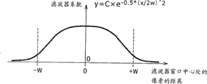
尽管使用位于滤波器窗口中心处的像素值作为伊普西龙滤波器中的参考级是常见的,但是在该情况下像素中的特定点不平滑。为此,边缘保留LPF 65包括低通滤波器,其利用被设置为位于滤波器窗口中心的像素和在邻近该像素的预定位置处排列的多个像素的加权平均值的参考值进行操作。应注意,可替换地,可使用位于滤波器窗口中心的像素和在邻近该像素的预定位置处排列的多个像素的简单平均值作为参考级。
Although it is common to use the pixel value at the center of the filter window as a reference level in an Ipsilon filter, certain points in the pixel are not smooth in this case. To this end, the edge-preserving
另一方面,在单个伊普西龙滤波器进行的处理中,可平滑的频带被偏置。因而,组合通过具有彼此不同的阈值的多个低通滤波器的处理获得的信号,以在本实施例中使用。 On the other hand, in the processing by a single Ipsilon filter, smoothable frequency bands are biased. Thus, signals obtained through processing of a plurality of low-pass filters having thresholds different from each other are combined for use in this embodiment. the
图11是例示了边缘保留LPF 65的详细配置例子的图。如上所述,边缘保留LPF 65是低通滤波器,被设计为从输入信号Y’的原始图像中去除细节分量,以正确地仅仅提取原始图像的发光分量。
FIG. 11 is a diagram illustrating a detailed configuration example of the edge-preserving
馈送到边缘保留LPF 65的信号Y’的图像被下采样器351稀疏化为具有较少数目的像素的图像,并被存储在缓冲器352中。由此,在稀疏像素数目 之后对图像滤波,提供更快的滤波。
The image of the signal Y' fed to the edge-preserving
此时,例如,生成如图12所示的图像,其像素数目被稀疏为原始图像的十六分之一。结果,如图13所示的图像被存储在缓冲器352中。在该例子中,原始图像显示出钟塔作为主体,相对于作为背景的天空。应注意,尽管这里将像素已经被稀疏为原始图像的十六分之一的图像被示出为在尺寸上小于原始图像以有助于描述,但是作为下采样器351的稀疏处理的结果,图像尺寸不必减小。
At this time, for example, an image as shown in FIG. 12 is generated, the number of pixels of which is thinned out to one sixteenth of the original image. As a result, an image as shown in FIG. 13 is stored in the
缓冲器352中存储的图像被提供给多尺度滤波器353。多尺度滤波器353包括超宽带边缘保留LPF 361和宽带边缘保留LPF 362。宽带边缘保留LPF362具有例如在尺寸上等于输入图像短边上的像素的2至20%的滤波器窗口。这里,术语“输入图像的短边”是指当成像元件的格式垂直和水平不对称时具有较少数目的像素的那条边。超宽带边缘保留LPF 361是一个滤波器窗口为宽带边缘保留LPF 362的滤波器窗口例如两至十倍的边缘保留LPF。
The images stored in the
从缓冲器352输出的信号被提供超宽带边缘保留LPF 361和宽带边缘保留LPF 362。由加法器363组合由两个LPF进行低通滤波的信号。
The signal output from the
例如,多尺度滤波器353处理过的图像表现为例如图14所示并被存储在缓冲器354中。 For example, the image processed by the multi-scale filter 353 appears, for example, as shown in FIG. 14 and is stored in the buffer 354 . the
与图13所示的图像相比,作为多尺度滤波器353滤波的结果,图14中所示的图像不再具有例如钟塔的时钟、墙上的图案和背景中的云。 Compared to the image shown in FIG. 13 , the image shown in FIG. 14 no longer has clocks such as clock towers, patterns on the wall and clouds in the background as a result of filtering by the multi-scale filter 353 . the
缓冲器354中存储的图像被提供给边缘保留上采样器356。边缘保留上采样器356基于从信号Y’获得的原始图像的边缘信息,增加在缓冲器354中存储的图像中的像素数目。即,边缘保留上采样器356将其像素已经被下采样器351稀疏化的图像恢复为具有原始像素数目的图像。 The images stored in buffer 354 are provided to edge preserving upsampler 356 . The edge-preserving upsampler 356 increases the number of pixels in the image stored in the buffer 354 based on the edge information of the original image obtained from the signal Y'. That is, the edge-preserving upsampler 356 restores the image whose pixels have been thinned out by the downsampler 351 into an image with the original number of pixels. the
此时,生成例如图15所示的图像,其像素数目已经增加到缓冲器354中存储的图像的十六倍。图15中的图像显示出作为暗物体的钟塔或主题,相对于作为亮物体的天空或背景。即,图像不在具有钟塔或天空中的精细图案,并且由暗区和亮区构成。在本实施例中,这样的图像被称为原始图像的发光分量。 At this time, an image such as that shown in FIG. 15 is generated, the number of pixels of which has been increased to sixteen times that of the image stored in the buffer 354 . The image in Figure 15 shows the clock tower or subject as a dark object, against the sky or background as a bright object. That is, the image no longer has clock towers or fine patterns in the sky, and is made up of dark and bright areas. In this embodiment, such an image is referred to as a luminous component of the original image. the
另外,在本实施例中,当增加图像的像素数目时,边缘保留上采样器356去除边缘钝感(bluntness)。 In addition, in this embodiment, the edge-preserving upsampler 356 removes edge bluntness when increasing the number of pixels of the image. the
下面将参照图16给出边缘保留上采样器的详细描述。 A detailed description of the edge-preserving upsampler will be given below with reference to FIG. 16 . the
简单地将像素数目已经稀疏化为其原始图像的十六分之一的图像的像素数增加16倍(像素计数的简单增加)产生如图像381所示的图像,在图像的暗区和亮区之间具有模糊的边缘或界限。在图像381右侧显示图表。该图表在横轴上显示像素位置,在纵轴上显示像素辉度,线383代表图像381的每个像素的辉度。
Simply increasing the pixel count of an image that has been thinned out to one sixteenth of its original image's pixel count by a factor of 16 (a simple increase in pixel count) produces an image such as that shown in
作为像素计数的简单增加的结果,线383具有接近梯形的形状,而它应该是接近矩形的形状。即,像素计数的简单增加使得像素辉度缓慢改变,而它应该急剧改变。因此,图像中不再清晰显示的边缘变得迟钝。
As a result of the simple increase in pixel count,
为此,本实施例提取作为像素计数的简单增加的结果而具有迟钝边缘的图像和原始图像之间的差,从所提取的差信号中去除边缘钝感,以恢复到原始图像。 To this end, the present embodiment extracts the difference between an image having dull edges as a result of a simple increase in pixel count and the original image, and removes edge dullness from the extracted difference signal to restore the original image. the
在原始图像382的右侧示出图表。该图表在横轴上显示像素位置,在纵轴上显示像素辉度,线384代表原始图像382的每个像素的辉度。线384所示的原始图像没有边缘钝感,但包含细节分量,因为它还必须由多尺度滤波器353进行滤波处理。在该例子中,线384的区域384a中包含的精细幅值是细节分量。
A graph is shown to the right of the
通过提取由线383所示的信号和由线384所示的信号之间的差而获得的信号的图像看起来例如如同图像385。在图像385下方示出图表。该图表在横轴上显示像素位置,在纵轴上显示像素辉度,线386代表图像385的每个像素的辉度。由线386所示的信号包含图像381的边缘钝感分量和原始图像382的细节分量。
An image of a signal obtained by extracting the difference between the signal shown by
为此,边缘保留上采样器将线386所示的信号乘以具有线387所示的特性的增益,以去除钝感分量。线387代表具有横轴上的输入和纵轴上的输出的增益的哦特性。该特性使得输出信号值随着输入信号值的改变而改变。线387具有所谓S形函数的特性。
To this end, the edge-preserving upsampler multiplies the signal shown by
与信号中包含的原始图像382的细节分量相比,信号中包含的图像381的边缘钝感分量的幅值更大。结果,线386所示的信号通过S形函数处理,提供如图像388所示的具有减少的钝感分量的图像。应注意,这里可使用固定值作为S形函数。然而,如果信号被调制为例如使得在非常有可能存在边缘的区域中强化S形特性,则可更有效地恢复边缘。
Compared with the detail component of the
在图像388下方示出图表。该图表在横轴上显示像素位置,在纵轴上显 示像素辉度,线389代表图像388的每个像素的辉度。与线386所示的信号相比,由于边缘钝感分量,由线389所示的信号的幅值更小。
Below the image 388 a graph is shown. The graph shows pixel location on the horizontal axis and pixel intensity on the vertical axis, with line 389 representing the intensity of each pixel of
如上所述,在减少边缘钝感分量之后组合信号(由线382所示的信号)和原始图像382的信号(由线384所示的信号),这提供了像素计数增加的图像或图像391。在图像391下方示出图表。该图表在横轴上显示像素位置,在纵轴上显示像素辉度,线392代表图像391的每个像素的辉度。不同于由线383所示的信号,由线392所示的信号没有边缘钝感。此外,不同于由线384所示的信号,由线392所示的信号没有由于细节分量导致的精细幅值。
Combining the signal (signal shown by line 382 ) with the signal of the original image 382 (signal shown by line 384 ) after reducing the edge-sensitivity component, as described above, provides an image or
即,不同于像素计数简单增加的图像381,图像391清晰地显示出仅仅提取了图像的发光分量的图像中的边缘。
That is, unlike the
应注意,上采样处理不仅可以如本实施例所述那样实现,还可使用在J.Kopf和M.Cohen和D.Lischinski和M.Uyttendaele,“Joint Bilateral Upsampling”,Proc.SIGGRAPH 07,2007中公开的方法。然而,本实施例的上述方法确保采样处理的改善的效率和更高的准确度。 It should be noted that the upsampling process can not only be implemented as described in this example, but can also be used in J.Kopf and M.Cohen and D.Lischinski and M.Uyttendaele, "Joint Bilateral Upsampling", Proc.SIGGRAPH 07, 2007 public method. However, the above-described method of the present embodiment ensures improved efficiency and higher accuracy of sampling processing. the
如上所述,本实施例允许从图像中提取发光和细节分量,同时去除边缘钝感。另外,边缘保留LPF 65的滤波参数(例如,阈值)根据图像的动态范围自动设置,由此无需用户操作。
As described above, the present embodiment allows extraction of glow and detail components from an image while removing edge bluntness. In addition, the filter parameters (eg, threshold) of the edge-preserving
另外,本发明使得其像素已经被下采样器351稀疏化的图像被多尺度滤波器353进行滤波处理,之后由边缘保留上采样器356进行上采样操作以恢复具有原始像素数目的图像。这有助于显著减小滤波处理所需的时间和成本。 In addition, the present invention enables the image whose pixels have been thinned out by the downsampler 351 to be filtered by the multi-scale filter 353, and then upsampled by the edge-preserving upsampler 356 to restore the image with the original number of pixels. This helps to significantly reduce the time and cost required for the filtering process. the
如上所述,利用边缘保留LPF 65处理信号Y’提供了信号Y’的图像的发光分量信号Y’lp。发光分量信号Y’lp被提供给细节提取部分66、细节调整部分67和色调曲线处理部分68。
As described above, processing signal Y' with
细节提取部分66计算信号Y’和发光分量信号Y’lp之间的差,由此提取信号Y’的细节分量信号Y’de。细节分量信号Y’de被提供给细节调整部分67。此后,信号Y’的发光分量由色调曲线处理部分68进行灰度压缩,而信号Y’的细节分量由细节调整部分67进行灰度压缩。然而,应注意,细节调整部分67的灰度压缩实际上被设计为提供图像的细节的改善视图,而非压缩图像的动态范围。
The
细节调整部分67将细节分量信号Y’de乘以基于校正增益LUT 72获得 的增益,由此校正图像的细节分量。
The
图17例示了校正增益LUT的例子。校正增益LUT 72是将发光强度与增益相关联的表。在该例子中,由线411与发光强度相关联地定义增益。使用发光分量信号Y’lp的值作为发光强度,线411具有通过利用满足单调递增条件的平滑曲线对增益边界条件插值而获得的特性,从而当发光强度为0时,DetailGain(0)=kBr,并且当发光强度为上限Y’sup时,DetailGain(Y’sup)=kAr。然而,应注意,如果增益小于1,则图像在信号饱和区域变差。因而,增益被限制为始终是1或更大。
FIG. 17 illustrates an example of the correction gain LUT. The
由控制MPU 64基于预先结合检测部分63进行的处理而找到的自适应增益kAr和kBr,设置图17中所示的校正增益LUT 72。
The
基于如此获得的信号而获得的图像在亮区和暗区中的每个物体中具有更少的过曝光或曝光不足,由此按照可正确感知像素之间的辉度差的方式提供了具有细节分量(物体)的改善视图的图像。 The image obtained based on the signal thus obtained has less overexposure or underexposure in each object in the bright and dark areas, thereby providing images with details in such a way that the brightness difference between pixels can be correctly perceived. An image of an improved view of the component (object). the
另外,预先在校正增益LUT 72中存储增益使得可以例如通过简单地覆写部分LUT数据,容易地调整执行灰度压缩的程度。
In addition, storing the gain in the
色调曲线处理部分68将发光分量信号Y’lp乘以被确定为与发光分量信号Y’lp的值相称的色调曲线的增益,以便使得发光分量信号Y’lp进行灰度压缩。该色调曲线根据校正增益LUT 72确定,并且由以下所示的等式获得的值充当增益:
The tone
ToneCurve(Y’lp)=Y’lp×DetailGain(Y’lp) ToneCurve(Y’lp)=Y’lp×DetailGain(Y’lp)
这里,DetailGain(Y’lp)表示基于校正增益LUT 72获得的增益,并且ToneCurve(Y’lp)表示由色调曲线处理部分68使用的增益。
Here, DetailGain(Y'lp) denotes a gain obtained based on the
以上过程允许考虑到人眼的适应强度而压缩动态范围(灰度压缩)。 The above process allows the dynamic range to be compressed (grayscale compression) in consideration of the adaptation strength of the human eye. the
另一方面,例如,如果使用色调曲线处理部分68的处理作为成像装置10的图像质量参数,则装置设计者可例如设置期望的典型值,而非根据校正增益LUT 72设置色调曲线。在此情况下,仅仅需要基于检测部分63的处理结果来选择典型值。然而应注意,即使在此情况下,ToneCurve(Y’lp)/Y’lP必须限于始终为1或更大,以防止图像在信号饱和区域变差。
On the other hand, for example, if the processing of the tone
如上所述,例如,使用色调曲线处理部分68的处理作为图像质量参数使得可以独立于每个区域的自适应级来设置发光分量的灰度压缩色调曲线,由此允许没有约束的图像质量设计。
As described above, for example, using the processing of the tone
由加法器69组合信号(一个经过细节调整部分67的处理,另一个经过色调曲线处理部分68的处理),并且所得的信号被提供给RGB调制部分71作为信号Y’out。RGB调制部分71还接收通过对RGB信号进行减噪(NR)处理而获得的GRBNR信号。
The signals (one processed by the
在常用减噪处理中,通过基于ISO速度设置噪声强度而去除噪声。然而,当图像进行灰度压缩时,输出图像中噪声的视图受到增益的影响。 In common noise reduction processing, noise is removed by setting the noise intensity based on the ISO speed. However, when an image is compressed in grayscale, the view of noise in the output image is affected by the gain. the
例如,如果图18中所示的利用ISO速度s捕捉的图像431进行减噪处理432并进一步进行灰度压缩处理433,则作为灰度压缩处理的结果,图像431的亮区A中的像素值乘以增益kAr,而其暗区B中的像素值乘以增益kBr。 For example, if an image 431 captured with ISO speed s shown in FIG. 18 is subjected to noise reduction processing 432 and further to grayscale compression processing 433, as a result of the grayscale compression processing, the pixel value in the bright area A of the image 431 Multiplied by the gain kAr, while the pixel value in its dark area B is multiplied by the gain kBr. the
结果,当由于减噪处理432而没有噪声的图像进行灰度压缩处理433时,可通过区域A和B的增益再次增强噪声。在本实施例中,为此,减噪处理432将ISO速度设置为(kAr×s)以用作图像431的区域A中的像素的噪声密度,并将ISO速度设置为(kBr×s)以用作其区域B中的像素的噪声密度。更具体地,通过设置与基于校正增益LUT 72确定的增益相称的阈值,正确地去除噪声。
As a result, when the image without noise due to the noise reduction process 432 is subjected to the gray scale compression process 433, the noise can be enhanced again by the gains of the regions A and B. In this embodiment, for this purpose, the noise reduction processing 432 sets the ISO speed to (kAr×s) to be used as the noise density of the pixels in the region A of the image 431, and sets the ISO speed to (kBr×s) to use used as the noise density for pixels in its region B. More specifically, by setting a threshold commensurate with the gain determined based on the
在NR处理中,逐像素地调整伊普西龙滤波器的阈值εNR,以从输入信号中去除噪声分量。基于噪声标准偏差σ确定阈值εNR。当确定像素电荷x和ISO速度时,通过函数σ=fs(x)找到噪声标准偏差σ。应注意,确定与像素电荷x相称的该像素的亮度值。 In NR processing, the threshold εNR of the Ipsilon filter is adjusted pixel by pixel to remove noise components from the input signal. The threshold εNR is determined based on the noise standard deviation σ. When determining pixel charge x and ISO speed, the noise standard deviation σ is found by the function σ=fs(x). It should be noted that the brightness value of the pixel is determined commensurate with the pixel charge x. the
图19是例示了具有横轴上的噪声标准偏差σ和纵轴上的电子数x的上述函数的例子。在图19中,作为例子示出了两个函数,一个用于高灵敏度增益,另一个用于标准增益。 FIG. 19 illustrates an example of the above-described function with the noise standard deviation σ on the horizontal axis and the number of electrons x on the vertical axis. In FIG. 19, two functions are shown as an example, one for the high sensitivity gain and the other for the standard gain. the
另一方面,在NR处理中,在计算阈值εNR时考虑例如由装置设计者设置的图像质量因子。假设用于ISO速度s的图像质量因子是g(x,s),通过函数εNR=g(x,s)×fs(x)。 On the other hand, in the NR processing, an image quality factor set, for example, by a device designer is taken into account in calculating the threshold εNR. Assuming that the image quality factor for ISO speed s is g(x, s), by the function εNR = g(x, s) x fs(x). the
图20是例示了上述函数g(x,s)的例子的图,具有横轴上的图像质量因子g和纵轴上的电子数x。在该例子中,作为例子示出了两个函数,一个用于高灵敏度增益,另一个用于标准增益。 FIG. 20 is a graph illustrating an example of the above-mentioned function g(x, s), having the image quality factor g on the horizontal axis and the number of electrons x on the vertical axis. In this example, two functions are shown as examples, one for high sensitivity gain and the other for standard gain. the
在本实施例中,通过下面给出的等式找到反应增益效果的阈值εNRmod,以允许NR处理部分70使用阈值εNRmod进行NR处理。
In the present embodiment, the threshold εNRmod of the reaction gain effect is found by the equation given below to allow the
εNRmod=g(Gain×x,Gain×s)/Gain×fs(x) εNRmod=g(Gain×x, Gain×s)/Gain×fs(x)
这里,变量Gain是基于校正增益LUT 72确定的增益。
Here, the variable Gain is a gain determined based on the
以上过程确保在图像的任何区域中考虑了与增益的乘法的最优NR处理。 The above process ensures optimal NR processing that takes multiplication with gain into account in any region of the image. the
NR处理部分70使用如上所述确定的阈值εNRmod对RGB信号进行NR处理,生成信号RGBNR作为输出信号并将信号RGBNR提供到RGB调制部分71。
The
RGB调制部分71基于来自加法器69的信号调制来自NR处理部分70的信号RGBNR,输出通过以下所示的等式获得的信号RGBNRout作为代表由灰度压缩部分34进行的处理的结果的信号。
The
RGBNRout=(Yout/Y)×RGBNR RGBNRout=(Yout/Y)×RGBNR
这里,信号Yout和Y是分别由感觉均衡部分62进行的信号Y’out和Y’的非线性转换处理的逆转换处理所生成的线性信号。即,馈送到灰度压缩部分34的图像的RGB信号被亮度信号生成部分61转换为代表辉度的信号Y,并且图像基于信号Y进行灰度压缩。然后,进行灰度压缩的图像从灰度压缩部分34输出,再次充当RGB信号(信号RGBNRout)。
Here, the signals Yout and Y are linear signals generated by inverse conversion processing of the nonlinear conversion processing of the signals Y'out and Y' performed by the
接着将参照图21所示的流程图给出成像装置10的成像处理的描述。
Next, a description will be given of the imaging process of the
在步骤S11中,成像装置10捕捉预备图像。该预备图像的捕捉是为了在捕捉要记录正式(definitive)图像之前设置成像装置10的多种参数。
In step S11, the
在步骤S12中,成像装置10使得在步骤S11中的处理之后从图1的CCD31输出的信号首先进行白平衡部分32的处理。然后,解拼部分33将所得信号转换为RGB信号,并将RGB信号输出到灰度压缩部分34。
In step S12 , the
在步骤S13中,图2所示的亮度信号生成部分61从亏送到灰度压缩部分34的RGB信号中提取代表考虑了物体反射率的辉度的信号Y。应注意,此时,感觉均衡部分62非线性地转换信号Y以生成感觉均衡的辉度信号Y’,以便在后续检测处理和低通滤波处理中确保匹配人类感觉的信号处理。
In step S13, the luminance
在步骤S14中,检测部分63进行后面将参照图22描述的检测处理。这允许检测部分63对信号Y’进行检测处理。
In step S14, the
这里将参照图22中所示的流程图给出图21的步骤S14中的检测处理的详细描述。 Here, a detailed description will be given of the detection processing in step S14 of FIG. 21 with reference to the flowchart shown in FIG. 22 . the
在步骤S41中,检测部分63对输入信号(信号Y’)进行低通滤波处理。 这从图像中去除了频率比预设水平更高的分量。
In step S41, the
在步骤S42中,检测部分63计算平均值Ym,以将图像分为两个区域。在步骤S43中,检测部分63计算两个区域的平均值Yh和Yl,以再次计算平均值Ym。
In step S42, the
在步骤S44中,检测部分63确定值Ym是否收敛。检测部分63重复步骤S42至S44,直到检测部分63确定值Ym已经收敛。
In step S44, the
如上所述参照图3执行这些处理步骤。 These processing steps are performed as described above with reference to FIG. 3 . the
如果在步骤S44中确定值Ym已经收敛,则处理前进到步骤S45。 If it is determined in step S44 that the value Ym has converged, the process proceeds to step S45. the
检测部分63在步骤S45中暂时确定曝光参数。
The
如上所述进行检测处理。 Detection processing is performed as described above. the
返回参照图21,在步骤S14中的处理之后的步骤S15中,控制MPU 64对具有等于或大于饱和水平的值的像素的数目进行计数,并基于该像素数目确定成像曝光是否合适。
Referring back to FIG. 21 , in step S15 following the processing in step S14, the
如果在步骤S15中确定曝光不合适,则处理返回步骤S11,其中例如成像装置10被控制MPU 64控制为减少曝光和再次捕捉预备图像。
If it is determined in step S15 that the exposure is not appropriate, the process returns to step S11, where, for example, the
如果在步骤S15中确定曝光合适,则处理前进到步骤S16。 If it is determined in step S15 that the exposure is appropriate, the process proceeds to step S16. the
在步骤S16中,控制MPU 64最终确定曝光参数,如自适应增益kAr和kBr。此时,提供到边缘保留LPF 65的阈值ε也被设置为参数。此时,另一方面,基于由步骤S14中的检测处理找到的平均值Yh获得的曝光值EVh可被重新设置为默认曝光值。这样做的原因是如果使用与亮区相称的曝光水平捕捉图像,则可以防止图像中的噪声变得过强。在此情况下,重新找到自适应增益kAr和kBr以最终确定曝光参数。
In step S16, the
由于所获得的自适应增益kAr和kBr,另一方面,控制MPU 64在此时设置校正增益LUT 72,由此具体生成例如图17中所示的线411。线411将发光强度与增益相关联。
Due to the obtained adaptive gains kAr and kBr, on the other hand, the
成像装置10在步骤S17中捕捉正式图像。结果,从CCD 31输出的信号首先进行白平衡部分32的处理。然后,所得信号被解拼部分33转换为RGB信号,其被输出到灰度压缩部分34。
The
在步骤S18中,灰度压缩部分34进行后面将参照图23中所示的流程图描述的灰度压缩处理。
In step S18, the
在步骤S19中,成像装置10进行多种预定信号处理任务。这些处理与 图1中所示的线性矩阵部分35、RGB伽玛校正部分36、BT.601矩阵部分37、Y伽玛校正部分38和色差矩阵部分39所处理的那些相关联。
In step S19, the
在步骤S20中,装置色阶压缩部分40例如根据输出装置的色阶进行色阶压缩处理。如上所述,在本实施例中,在灰度压缩(步骤S18)之后进行色阶压缩处理,由此防止诸如由于部分颜色灰度的损失或色彩偏离而引起的单调图像等的问题。
In step S20, the device
然后,在步骤S21中,从装置色阶压缩部分40输出的图像数据被存储在存储文件41中。
Then, the image data output from the device
如上所述进行成像处理。 Imaging processing was performed as described above. the
接着将参照图23中所示的流程图给出图21中所示的步骤S18中的灰度压缩处理的详细描述。 Next, a detailed description will be given of the gradation compression processing in step S18 shown in FIG. 21 with reference to the flowchart shown in FIG. 23 . the
在步骤S61中,进行后面将参照图24所述的边缘保留LPF 65的处理。
In step S61, processing of the
这里将参照图24中所示的流程图给出图23的步骤S61中的边缘保留低通滤波处理的详细描述。 Here, a detailed description will be given of the edge-preserving low-pass filtering process in step S61 of FIG. 23 with reference to the flowchart shown in FIG. 24 . the
在步骤S81中,下采样器351稀疏化来自馈送到边缘保留LPF 65的信号Y’的图像的像素,由此产生具有更少像素的图像,并将图像存储在缓冲器352中。此时,例如,生成如图12所示的图像,其像素数目已经被稀疏化为原始图像的十六分之一。结果,在缓冲器352中存储如图13所示的图像。
In step S81, the down-sampler 351 thins out the pixels of the image from the signal Y' fed to the edge-preserving
在步骤S82和S83中,缓冲器352中存储的图像被提供给多尺度滤波器353,其中图像进行超宽带边缘保留LPF 361和宽带边缘保留LPF 362的处理。然后,在步骤S84中,由加法器363组合两个信号(一个进行超宽带边缘保留LPF 361的处理,另一个进行宽带边缘保留LPF 362的处理)并存储在缓冲器354中。
In steps S82 and S83, the image stored in the
在步骤S85中,存储在缓冲器354中的图像被提供给边缘保留上采样器356。此时,如上面参照图16所述,例如,提取两个图像(作为像素计数的简单增加的结果而具有边缘顿感的图像和原始图像)之间的差。所提取的差信号进行适合于去除边缘顿感的处理。然后,所得信号与原始图像组合,以产生像素计数增加的图像。 In step S85 , the image stored in the buffer 354 is supplied to the edge-preserving upsampler 356 . At this time, as described above with reference to FIG. 16 , for example, a difference between two images (an image having edge blur as a result of a simple increase in the pixel count and an original image) is extracted. The extracted difference signal is processed suitable for removing edge stuttering. The resulting signal is then combined with the original image to produce an image with an increased pixel count. the
如上所述进行边缘保留低通滤波处理。 The edge-preserving low-pass filtering process is performed as described above. the
返回参照图23,在步骤S61中的处理之后,细节提取部分66在步骤S62 中计算信号Y’和发光分量信号Y’lp之间的差,由此提取信号Y’的图像的细节分量信号Y’de,并将细节分量信号Y’de提供给细节调整部分67。
Referring back to FIG. 23, after the processing in step S61, the
在步骤S63中,细节调整部分67基于校正增益LUT 72设置增益。此时,如上参考图17所述,基于发光分量信号Y’lp设置增益。
In step S63, the
在步骤S64中,细节调整部67通过将细节分量信号Y’de乘以在步骤63的处理中设置的增益,校正图像的细节分量。
In step S64, the
在步骤S65中,NR处理部分70找到如上所述反应增益的效果的阈值εNRmod,并基于阈值εNRmod设置噪声参数。
In step S65, the
在步骤S66中,基于在步骤S65的处理中设置的噪声参数进行NR处理。此时,信号RGBNR被提供给RGB调制部分71作为输出信号。
In step S66, NR processing is performed based on the noise parameters set in the processing of step S65. At this time, the signal RGBNR is supplied to the
在步骤S67中,色调曲线处理部分68通过将发光分量信号Y’lp的值乘以被确定为与发光分量信号Y’lp相称的色调曲线的增益,对发光分量信号Y’lp进行灰度压缩。
In step S67, the tone
在步骤S68中,加法器69组合两个信号,一个来自步骤S64中的处理之后的细节调整部分67,另一个来自步骤S67中的处理之后的色调曲线处理部分68,并将所得信号提供给RGB调制部分71作为信号Y’out。
In step S68, the
在步骤S69中,RGB调制部分71基于从基于在步骤S68中的处理之后从加法器69提供的信号,调制从NR处理部分70提供的信号RGBNR。
In step S69, the
在步骤S70中,输出信号RGBNRout作为代表步骤S69中的处理的结果的信号,还作为代表由灰度压缩部分34进行的处理的结果的信号。
In step S70 , the signal RGBNRout is output as a signal representing the result of the processing in step S69 and also as a signal representing the result of the processing by the
如上所述进行灰度压缩。这确保输入信号对比度的正确压缩,由此提供在亮区和暗区中细节感觉均丰富的图像。 Grayscale compression is performed as described above. This ensures correct compression of the contrast of the input signal, thereby providing an image with a rich sense of detail in both bright and dark areas. the
另外,如果仅仅通过细节调整部分67的处理增强细节分量而不金子那个色调曲线处理部分68的处理,则有可能逐个区域地提供图像的改善视图,同时维持输入图像对比度不变。
In addition, if only the detail component is enhanced by the processing of the
顺带地,在传统数字静态相机的信号处理中,例如,通过调整RAW信号(成像器输出信号)的高亮度区域中的灰度曲线来进行更多或更少的全局灰度压缩。根据全局灰度压缩确定成像曝光。如果另外添加不同的灰度压缩处理,则成像曝光设置和灰度曲线之间的关系混乱,使得不能生成所期望的图像。此外,减噪不如预期那样有效,导致噪声的更差的感觉。如果本发明应用于诸如数字静态相机的能够通过调整RAW信号的高亮度区域中的灰度 曲线来进行更多或更少的全局灰度压缩的成像装置,则按照以下所述的方式相对于彼此高效地进行一般相机信号处理和本实施例的处理。 Incidentally, in the signal processing of a conventional digital still camera, for example, more or less global gradation compression is performed by adjusting a gradation curve in a high-brightness region of a RAW signal (imager output signal). Determine imaging exposure based on global grayscale compression. If different gradation compression processing is additionally added, the relationship between the imaging exposure setting and the gradation curve is confused, so that a desired image cannot be generated. Furthermore, noise reduction is not as effective as expected, resulting in a worse perception of noise. If the present invention is applied to an imaging device such as a digital still camera capable of more or less global grayscale compression by adjusting the grayscale curve in the high-brightness region of the RAW signal, then relative to each other in the manner described below General camera signal processing and the processing of this embodiment are efficiently performed. the
在传统的相机信号处理中,RGB信号和信号Y(亮度信号)进行与代表输入信号的动态范围的值DRIN相称的伽玛校正,由此通过图像的高亮度区域的膝状压缩(knee compression)而压缩动态范围。 In conventional camera signal processing, the RGB signal and the signal Y (luminance signal) undergo gamma correction commensurate with the value DRIN representing the dynamic range of the input signal, thereby passing knee compression in the high-brightness areas of the image while compressing the dynamic range. the
图25是例示了传统灰度压缩处理中的RGB伽玛校正的例子的图。如该图中所述,线501至503分别例示了当代表输入信号的动态范围的值DRIN是150%(D范围:150%)、300%(D范围:300%)和600%(D范围600%)时在与主体亮度相称的校正之后RGB信号的输出值(RGBout)的特性。 FIG. 25 is a diagram illustrating an example of RGB gamma correction in conventional gradation compression processing. As described in the figure, lines 501 to 503 respectively illustrate when the value DRIN representing the dynamic range of the input signal is 150% (D range: 150%), 300% (D range: 300%), and 600% (D range 600%) characteristics of the output value (RGBout) of the RGB signal after correction commensurate with the brightness of the subject. the
图26是例示了传统灰度压缩处理中Y伽玛校正的例子的图。如图所示,线511至513分别例示了当代表输入信号的动态范围的值DRIN是150%(D范围:150%)、300%(D范围:300%)和600%(D范围600%)时在与主体亮度相称的校正之后信号Y的输出值(Yout)的特性。
FIG. 26 is a diagram illustrating an example of Y gamma correction in conventional gradation compression processing. As shown,
例如,基于相机的内部存储器中存储的RGB伽玛表和Y伽玛表,进行这样的信号校正。 Such signal correction is performed, for example, based on an RGB gamma table and a Y gamma table stored in the camera's internal memory. the
在能够在开发RAW信号时通过调整高亮度区域中的灰度曲线而进行全局灰度压缩的数字静态相机等中,如图25和图26所示自动校正输入信号。 In a digital still camera or the like capable of global gradation compression by adjusting a gradation curve in a high-brightness area when developing a RAW signal, an input signal is automatically corrected as shown in FIGS. 25 and 26 . the
如果向能够在开发RAW信号时通过调整高亮度区域中的灰度曲线而进行全局灰度压缩的数字静态相机等添加例如上面参照图1至24所述的处理,即,如果在图21的步骤S19中的处理期间将本发明应用于例如适合于如图25和图26所示校正输入信号的数字静态相机,则仅仅需要设置具有被设为(kBr/kAr)×DRIN的动态范围的RGB伽玛和Y伽玛表。 If, for example, the processing described above with reference to FIGS. Applying the present invention during the processing in S19 to, for example, a digital still camera suitable for correcting an input signal as shown in FIGS. Ma and Y gamma tables. the
这样做的原因是作为图21的步骤S18中的处理的结果,已经通过kBr/kAr折叠(fold)压缩输入图像的动态范围DRIN。 The reason for this is that the dynamic range DRIN of the input image has been compressed by kBr/kAr folding as a result of the processing in step S18 of FIG. 21 . the
图27和图28是例示了具有被设置为(kBr/kAr)×DRIN的动态范围的RGB伽玛和Y伽玛表的例子的图。 27 and 28 are diagrams illustrating examples of RGB gamma and Y gamma tables having a dynamic range set to (kBr/kAr)×DRIN. the
图27示出了横轴上的RGB信号的输入值(RGBin)和纵轴上的RGB信号的输出值(RGBout)。线521至523分别例示了当代表输入信号的动态范围的值DRIN是150%(D范围:150%)、300%(D范围:300%)和600%(D范围600%)时在与RGB信号的输入值相称的校正之后RGB信号的输出值(Yout)的特性。
FIG. 27 shows input values (RGBin) of RGB signals on the horizontal axis and output values (RGBout) of RGB signals on the vertical axis.
图28示出了横轴上的信号Y的输入值(Yin)和纵轴上的信号Y的输出值(Yout)。线531至533分别例示了当代表输入信号的动态范围的值DRIN是150%(D范围:150%)、300%(D范围:300%)和600%(D范围600%)时在与信号Y的输入值相称的校正之后信号Y的输出值(Yout)的特性。
FIG. 28 shows the input value (Yin) of the signal Y on the horizontal axis and the output value (Yout) of the signal Y on the vertical axis.
由此,如果再次基于自适应增益kBr和kAr设置RGB和Y伽玛表,则可以将本发明应用于传统的数字静态相机等,而不会显著地改变其配置。 Thus, if the RGB and Y gamma tables are set again based on the adaptive gains kBr and kAr, the present invention can be applied to a conventional digital still camera or the like without significantly changing its configuration. the
由此,为了校正RGB和Y伽玛表,仅仅需要将信号(一个代表自适应增益kBr,另一个代表自适应增益kAr)从灰度压缩部分34经由成像装置10的未示出的总线提供给RGB伽玛校正部分36和Y伽玛校正部分38,从而分别由RGB伽玛校正部分36和Y伽玛校正部分38校正RGB和Y伽玛表。
Thus, in order to correct the RGB and Y gamma tables, it is only necessary to supply signals (one representing the adaptive gain kBr and the other representing the adaptive gain kAr) from the gray
另外,如上所述,色调曲线处理部分68将发光分量信号Y’lp乘以被确定为与发光分量信号Y’lp的值相称的色调取消的增益,以便对发光分量信号Y’lp进行灰度压缩。根据校正增益LUT 72确定该色调曲线。
In addition, as described above, the tone
现在假设在色调曲线中,装置设计者不设置任何期望的典型值,并且由组合两个信号的加法器69生成的信号的值是Y’out,则保持如下所示的等式。
Assuming now that in the tone curve, the device designer does not set any desired typical value, and the value of the signal generated by the
Y’out=ToneCurve(Y’lp)+DetailGain(Y’lp)×Y’de Y'out=ToneCurve(Y'lp)+DetailGain(Y'lp)×Y'de
=Y’lp×DetailGain(Y’lp)+DetailGain(Y’lp)×Y’de =Y’lp×DetailGain(Y’lp)+DetailGain(Y’lp)×Y’de
=DetailGain(Y’lp)×(Y’lp+Y’de) =DetailGain(Y’lp)×(Y’lp+Y’de)
即,如果色调曲线处理部分68的色调曲线完全与校正增益LUT 72有关,则通过简单地将信号Y’(=Y’lp+Y’de)即原始图像乘以由校正增益LUT 72确定的增益(DetailGain(Y’lp))而获得由组合两个信号的加法器69生成的信号。
That is, if the tone curve of the tone
如果色调曲线处理部分68的色调曲线完全与校正增益LUT 72有关,则可以共用色调曲线处理部分68和细节调整部分67,由此提供装置的更加简单的配置。
If the tone curve of the tone
如果由被配置为如上参照图2所述的灰度压缩部分34进行灰度压缩,则两个差增益被用作图像的发光分量和细节分量的乘数。即,如果通过发光分量的灰度压缩获得的信号的特性如图29的线552所示,则通过细节分量的灰度压缩获得的信号的特性如图29中的线551所示。
If gradation compression is performed by the
图29示出了横轴上的发光分量信号Y’lp的输入值Y’lpin和纵轴上的在 灰度压缩后输出的发光分量信号Y’lp的输出值Y’lpout。如果在图29的图表上叠加显示出横轴上的细节分量信号的输入值和纵轴上的在灰度压缩后输出的细节分量信号的输出值的图表,则获得由线551所示的特性。
Fig. 29 shows the input value Y'lpin of the luminescence component signal Y'lp on the horizontal axis and the output value Y'lpout of the luminescence component signal Y'lp output after gradation compression on the vertical axis. If a graph showing the input value of the detail component signal on the horizontal axis and the output value of the detail component signal output after gradation compression on the vertical axis is superimposed on the graph of FIG. 29 , the characteristic shown by the
色调曲线处理部分68的色调曲线完全与校正增益LUT 72有关的事实意味着线511一开始所示的细节分量信号的输出值的特性与图29中线552所示的相似。
The fact that the tone curve of the tone
图30是例示了图1中所示的灰度压缩部分34的另一详细配置例子的图。该图示出了具有比图2所示更简单的配置的灰度压缩部分34的例子。
FIG. 30 is a diagram illustrating another detailed configuration example of the
省略了该图中亮度信号生成部分61和边缘保留LPF 65的详细描述,因为它们与上面参照图2所述的相同。
Detailed descriptions of the luminance
不同于图2中所示的灰度压缩部分34,图30所示的灰度压缩部分34没有细节调整部分67、色调曲线处理部分68和加法器69,但具有增益处理部分73。合并类似于校正增益LUT 72的LUT,增益处理部分73基于LUT标识从边缘保留LPF 65输出的与发光分量信号Y’lp相称的增益,并将增益输出到NR处理部分70和RGB调制部分71。
Unlike the
在图30所示的例子中,增益处理部分73的输出信号(增益)被提供给NR处理部分70。NR处理部分70使用如上所述确定的阈值εNRmod对RGB信号进行NR处理,生成信号RGBNR作为输出信号并将信号RGBNR提供给RGB调制部分71。
In the example shown in FIG. 30 , the output signal (gain) of the
RGB调制部分71将RGB信号乘以来自增益处理部分73的增益。RGB调制部分71还调制来自NR处理部分70的信号RGBNR,输出通过以下所示等式获得的信号RGBNRout,作为代表由灰度压缩部分34进行的处理的结果的信号。在图30所示的例子的情况下,由以下所示的等式表示信号RGBNRout。
The
RGBNRout={DetailGain(Y’lp)}1/γ×RGBNR RGBNRout={DetailGain(Y'lp)} 1/γ ×RGBNR
其中{}1/γ是非线性到线性转换。 where {} 1/γ is the nonlinear to linear conversion.
接着将参照图31所示的流程图给出当灰度压缩部分34被配置为如图30所示时的灰度压缩处理的例子的描述。
Next, a description will be given of an example of gradation compression processing when the
在步骤S101中,边缘保留LPF 65进行处理。该处理与上面参照图24所示的流程图所述的相同。因而省略其详细描述。
In step S101, the
在步骤S102中,增益处理部分73基于内部LUT设置增益。此时,如 上参照图17所述,基于发光分量信号Y’lp的值设置增益。
In step S102, the
在步骤S103中,NR处理部分70如上所述找到反映增益效果的阈值εNRmod,并基于阈值εNRmod设置噪声参数。
In step S103, the
在步骤S104中,基于在步骤S103的处理中设置的噪声参数,进行NR处理。此时,信号RGBNR被提供给RGB调制部分71作为输出信号。
In step S104, NR processing is performed based on the noise parameters set in the processing of step S103. At this time, the signal RGBNR is supplied to the
在步骤S105中,RGB调制部分71将RGB信号(即发光分量信号Y’lp+细节分量信号Y’de)乘以在步骤S102的处理中设置的增益,由此进行灰度压缩。
In step S105, the
在步骤S106中,RGB调制部分71基于来自增益处理部分73的信号调制来自NR处理部分70的信号RGBNR。
In step S106 , the
然后,在步骤S107中,输出信号RGBNRout,作为代表由灰度压缩部分34进行的处理的结果的信号。
Then, in step S107 , the signal RGBNRout is output as a signal representing the result of the processing performed by the
如上所述进行灰度压缩处理。这确保输入信号对比度的正确压缩,由此提供在整个灰度上的细节感觉丰富的图像,并且与图23所示的情况相比简化了处理。 Grayscale compression processing is performed as described above. This ensures correct compression of the input signal contrast, thereby providing an image that is perceptually rich in detail across grayscale, and simplifies processing compared to the situation shown in FIG. 23 . the
另外,本实施例提供例如通过传统RGB色调曲线处理获得的图像的改善的质量。例如,传统RGB色调曲线处理可能由于全局灰度压缩而导致细节丢失或者由于RGB信号的非线性处理而导致色彩偏离,由此导致图像质量恶化。 In addition, the present embodiment provides improved quality of images such as obtained by conventional RGB tone curve processing. For example, conventional RGB tone curve processing may result in loss of detail due to global grayscale compression or color deviation due to non-linear processing of RGB signals, thereby deteriorating image quality. the
例如,根据本实施例使用边缘保留LPF 65和细节提取部分66从图像中提取发光和细节分量。然后,进行局部处理,其中基于传统RGB色调曲线处理中的预设色调曲线对图像的发光和细节部分进行不同的色调曲线处理(灰度校正处理)。与传统RGB色调曲线处理相比,这提供了图像的改善的质量。
For example, according to the present embodiment, the light emission and detail components are extracted from the image using the
在此情况下,当在传统RGB色调曲线处理中给出的预设色调曲线的增益由UserToneCurve(Y’)表示时,要乘以细节分量的增益DetailGain(Y’lp)通过以下所示的等式找到。 In this case, when the gain of the preset tone curve given in conventional RGB tone curve processing is represented by UserToneCurve(Y'), the gain DetailGain(Y'lp) to be multiplied by the detail component is obtained by the equation shown below format found. the
DetailGain(Y’lp)=UserToneCurve(Y’lp)/Y’lp DetailGain(Y’lp)=UserToneCurve(Y’lp)/Y’lp
然后,仅仅需要通过以下所示的等式找到要乘以发光分量的增益ToneCurve(Y’lp)。 Then, it is only necessary to find the gain ToneCurve(Y'lp) to be multiplied by the luminescence component by the equation shown below. the
ToneCurve(Y’lp)=UserToneCurve(Y’lp) ToneCurve(Y'lp)=UserToneCurve(Y'lp)
这容易地实现了通过色调曲线处理获得图像的改善的质量。 This easily achieves improved quality of images obtained by tone curve processing. the
在图1中,另一方面,给出了描述,使得解拼部分33将拼嵌图像转换(解拼)为RGB信号并将RGB信号输出到灰度压缩部分34。然而可替换地,拼嵌图像信号,即Bayer RAW信号可“原样”输出到灰度压缩部分34。
In FIG. 1 , on the other hand, a description is given such that the
在此情况下,灰度压缩部分34的亮度信号生成部分61使用通过插值Bayer RAW信号而获得的RGB信号生成信号Y。NR处理部分70进行BayerRAW信号的NR处理。然后,RGB调制部分71仅仅需要调制Bayer RAW信号而非RGB信号。
In this case, the luminance
如果Bayer RAW信号被“原样”输出到灰度压缩部分34,则成像装置10被配置为如图32所示。在图32中,与图1中相同的部分用相同的附图标记表示。在图32所示的例子中,在白平衡部分32和解拼部分33之间提供灰度压缩部分34。图32所示的成像装置10在所有其他方面中与图1所示的相同。
If the Bayer RAW signal is output to the
可替换地,成像装置10可被配置为如图33所示。在图33中,与图1中相同的部分用相同的附图标记表示。在图33所示的例子中,在线性矩阵部分35和RGB伽玛校正部分36之间提供灰度压缩部分34。图33所示的成像装置10在所有其他方面中与图1所示的相同。
Alternatively, the
另外,成像装置10可被配置为在伽玛校正之后进行灰度压缩。在此情况下,在灰度压缩之前进行理想的sRGB伽玛校正,之后,进行灰度压缩。然后,在灰度压缩之后,伽玛图像质量和膝状压缩分量由RGB德尔塔/伽玛校正部分进行校正。
In addition, the
图34是例示了适合于在伽玛校正处理之后进行灰度压缩的成像装置10的配置例子的图。在图34中,与图1中相同的部分用相同的附图标记表示。不同于图1中所示的成像装置,图34的例子中所示的成像装置10没有RGB伽玛校正部分36,但有sRGB伽玛校正部分42和RGB德尔塔/伽玛校正部分43。sRGB伽玛校正部分42进行理想sRGB伽玛校正处理。RGB德尔塔/伽玛校正部分43校正伽玛图像质量和膝状压缩分量。在图34中,在sRGB伽玛校正部分42和RGB德尔塔/伽玛校正部分43之间提供灰度压缩部分34。图34中所示的成像装置10在所有其他方面中与图1所示的相同。
FIG. 34 is a diagram illustrating a configuration example of the
图35是例示了图11中所示的超宽带边缘保留LPF 361或宽带边缘保留LPF 362的详细配置例子的框图。如上所述,缓冲器352的输出信号被提供 给超宽带边缘保留LPF 361或宽带边缘保留LPF 362。在这些滤波器之一中进行了边缘保留地通滤波处理的信号被输出到加法器363。这些滤波器被设计为平滑图像的所有区域而非边缘,同时保留边缘完整。
FIG. 35 is a block diagram illustrating a detailed configuration example of the ultra-wideband edge-preserving LPF 361 or the wideband edge-preserving LPF 362 shown in FIG. 11 . As mentioned above, the output signal of
应注意,在图2的框图中所示的边缘保留LPF 65中,如图11所示,为了描述方便,包括例如下采样器351和边缘保留上采样器356的功能块被称为边缘保留LPF。然而,如果除了一般线性低通滤波器(LPF)的功能之外,滤波器还能够根据输入值和给定参考级(例如,滤波器窗口的中心值)之间的差调整滤波器窗口中的输入值的效果在滤波处理的输出上的比例,则该滤波器也称为边缘保留LPF。即,被配置为图11中的超宽带边缘保留LPF 361或宽带边缘保留LPF 362的每个滤波器可被称为边缘保留LPF。
It should be noted that in the edge-preserving
如图35所示,超宽带边缘保留LPF 361或宽带边缘保留LPF 362(这里简称为边缘保留LPF)包括加法系数确定处理部分601、系数归一化处理部分602、乘法器603和604、积分部分605和积分结束确定部分606。
As shown in FIG. 35 , the ultra-wideband edge-preserving LPF 361 or the wideband edge-preserving LPF 362 (abbreviated as edge-preserving LPF herein) includes an addition coefficient
缓冲器352中存储的图像中的滤波器窗口的中心处的像素被提供给加法系数确定处理部分601的参考级计算部分611。参考级计算部分611基于所提供的像素的值计算参考级。例如,如上参照图9所述,位于滤波器窗口中心处的像素值被“原样”用作参考级。
The pixel at the center of the filter window in the image stored in the
从参考级计算部分611输出的参考级被提供给减法器612。减法器612基于馈送到该边缘保留LPF的每个像素值和参考级之间的差,并将计算结果提供给加法系数输出部分613。
The reference level output from the reference
加法系数输出部分613基于减法器612的输出值和从图2中所示的控制MPU 64提供的阈值ε,输出加法系数。加法系数是在边缘保留LPF的滤波处理中使用的信号方向上的权重。另一方面,该系数是范围滤波器系数。此时,例如,如图36所示输出加法系数。
The addition
图36是在横轴上示出减法器612的输出值并且在纵轴上示出从加法系数输出部分613输出的加法系数的图。如该图所示,当减法器612的输出值(即,每个像素值和参考级之间的差)落入+ε和-ε之间的范围内时,加法系数输出部分613输出值1作为加法系数。另一方面,当减法器612的输出值落在+ε和-ε之间的范围外时,加法系数输出部分613输出值0作为加法系数。
FIG. 36 is a graph showing the output value of the
乘法器603将从加法系数输出部分613输出的加法系数与馈送到边缘保留LPF的每个像素值相乘。乘法器603的加法系数的乘法防止像素值(其与参考级之间的差不落入+ε和-ε之间的范围内)被提供给乘法器604。
The
乘法器604将乘法器603的输出值和滤波器系数相乘。滤波器系数是在边缘保留LPF的滤波处理中使用的空间方向上的权重。另一方面,该系数是域滤波器系数。这里,根据感兴趣的像素和位于滤波器窗口中心处的像素之间的距离确定要乘的滤波器系数。
The
图37是描述滤波器系数的图。该图在横轴上例示了感兴趣的像素和位于滤波器窗口中心处的像素之间的距离,并且在纵轴上例示了滤波器系数。如该图所示,当要处理的像素(感兴趣的像素)和位于滤波器窗口中心处的像素之间的距离落入范围+W和-W内时,提供给定滤波器系数。另一方面,如果要处理的像素(感兴趣的像素)和位于滤波器窗口中心处的像素之间的距离落入范围+W和-W外,则提供滤波器系数0。另外,当感兴趣的像素和位于滤波器窗口中心处的像素之间的距离落入范围+W和-W内时,滤波器系数的积分为1。这里,参考数字W是与上面参照图9所述的像素位置宽度W相关联的值,并且预先设置在边缘保留LPF中。 Fig. 37 is a diagram describing filter coefficients. The figure illustrates the distance between the pixel of interest and the pixel located at the center of the filter window on the horizontal axis, and the filter coefficient on the vertical axis. As shown in the figure, when the distance between the pixel to be processed (pixel of interest) and the pixel located at the center of the filter window falls within the range +W and −W, a given filter coefficient is provided. On the other hand, if the distance between the pixel to be processed (pixel of interest) and the pixel located at the center of the filter window falls outside the range +W and -W, a filter coefficient of 0 is provided. Additionally, the integral of the filter coefficients is 1 when the distance between the pixel of interest and the pixel located at the center of the filter window falls within the range +W and -W. Here, the reference numeral W is a value associated with the pixel position width W described above with reference to FIG. 9 , and is set in advance in the edge preserving LPF. the
由于乘法器603的滤波器系数的乘法和后面将描述的归一化,能通过求和获得滤波器窗口中的平均像素值。
Due to multiplication of filter coefficients by the
从乘法器604输出的值均被提供到积分部分605以求和。当从乘法器604输出的用于位于滤波器窗口内的像素的所有值被提供给积分部分605并求和时,积分结束确定部分606将求和结果输出到除法器624。
The values output from the
另一方面,乘法器621将从加法系数输出部分613输出的加法系数和上述滤波器系数相乘。从乘法器621输出的值均被提供到积分部分622以求和。当从乘法器621输出的用于位于滤波器窗口内的像素的所有值被提供给积分部分622并求和时,积分结束确定部分623将求和结果输出到除法器624作为归一化系数。这是的可以找到滤波器窗口的所有像素中与参考级之间的差落入范围+ε和-ε内的像素的平均亮度值。
On the other hand, the
除法器624的输出是进行了边缘保留LPF的处理的像素值。结果,已经进行了边缘保留LPF的处理的像素值用滤波器窗口的所有像素中与参考级之间的差落入范围+ε和-ε内的像素的平均亮度值代替。
The output of the
即,边缘保留LPF基于与要处理的目标像素相关联的参考像素值(参考级)和阈值ε,确定临近要处理的目标像素的每个像素的值与参考级之间的差是否落入+ε和-ε之间的范围内。然后,仅仅其值和参考级之间的差落入+ε 和-ε之间的范围内的那些像素才被确定为有效并用于计算上述平均值以进行平滑。 That is, the edge-preserving LPF determines whether the difference between the value of each pixel adjacent to the target pixel to be processed and the reference level falls within + In the range between ε and -ε. Then, only those pixels whose value and the difference between the reference level fall within the range between +ε and −ε are determined to be valid and used to calculate the above average for smoothing. the
应注意,给出了描述,使得图35示出了图11中超宽带边缘保留LPF 361或宽带边缘保留LPF 362的详细配置例子,图11中的多尺度滤波器可被配置为如图35所示。即,图2中被示出为边缘保留LPF 65的功能块不必包括超宽带边缘保留LPF 361和宽带边缘保留LPF 362。
It should be noted that the description is given so that Fig. 35 shows a detailed configuration example of the ultra-wideband edge-preserving LPF 361 or the wideband edge-preserving LPF 362 in Fig. 11, the multi-scale filter in Fig. 11 can be configured as shown in Fig. 35 . That is, the functional block shown as edge-preserving
下面将参照图38中所示的流程图给出图35所示的边缘保留LPF的滤波处理的描述。例如,该处理被执行为图24的步骤S82或S83中的处理。 A description will be given below of the filtering process of the edge preserving LPF shown in FIG. 35 with reference to the flowchart shown in FIG. 38 . For example, this processing is performed as the processing in step S82 or S83 of FIG. 24 . the
在步骤S131中,参考级计算部分611基于所提供的像素值计算参考级。例如,如上面参照图9所述,位于滤波器窗口中心处的像素值被“原样”用作参考级。
In step S131, the reference
在步骤S132中,积分器605和622重置。
In step S132, the
在步骤S133中,滤波器窗口中的未处理像素被选择和提供给减法器612。
In step S133 , unprocessed pixels in the filter window are selected and supplied to the
在步骤S134中,加法系数输出部分613基于减法器612的输出值和从图2中所示的控制MPU 64提供的阈值ε,输出加法系数。此时,如图36所示,当加法器612的输出值落入+ε和-ε之间的范围内时,加法系数输出部分613输出值1作为加法系数。另一方面,当加法器612的输出值落在+ε和-ε之间的范围外时,加法系数输出部分613输出值0作为加法系数。
In step S134, the addition
然后,乘法器603将从加法系数输出部分613输出的加法系数与馈送到边缘保留LPF的每个像素值相乘。
Then, the
在步骤S135中,乘法器604将乘法器603的输出值和滤波器系数相乘。另一方面,乘法器621将从加法系数输出部分613输出的加法系数和滤波器系数相乘。此时,例如,当在步骤S133的处理中选择的像素(感兴趣的像素)和位于滤波器窗口中心处的像素之间的距离落入+W和-W之间的范围内时,提供值1作为滤波器系数。另一方面,当感兴趣的像素和位于滤波器窗口中心处的像素之间的距离落入+W和-W之间的范围外时,提供值0作为滤波器系数。
In step S135, the
在步骤S136中,积分部分605对作为步骤S135中的处理的结果而产生的值求和(相加)。
In step S136, the integrating
在步骤S137中,积分结束确定部分606和623确定滤波器窗口中的所有像素的值是否已经被求和。如果积分结束确定部分606和623确定滤波器窗口中的所有像素的值还必须要被求和,则处理返回到步骤S133。
In step S137, the integration
当积分结束确定部分606和623在步骤S137中确定滤波器窗口中的所有像素的值已经被求和,则积分结束确定部分606和623将求和结果输出到除法器624。
When the integration
在步骤S138中,除法器624进行除法并输出归一化值。
In step S138, the
如上所述进行边缘保留LPF的滤波处理。 The filtering processing of the edge-preserving LPF is performed as described above. the
图39是例示了边缘保留LPF的另一配置例子的框图。在图39中,与图35中相同的功能块用相同的附图标记表示,并且省略其详细描述。 Fig. 39 is a block diagram illustrating another configuration example of the edge preserving LPF. In FIG. 39 , the same functional blocks as those in FIG. 35 are denoted by the same reference numerals, and their detailed descriptions are omitted. the
在图39所示的例子中,加法系数输出部分613的输出被提供给乘法器603和减法器607。然后,减法器607计算从加法系数输出部分613输出的加法系数和值1.0之间的差。减法器607的输出被提供给乘法器608。乘法器608将从减法器607输出的差和从参考级计算部分611输出的参考级相乘并将乘积提供给加法器609。加法器609将从乘法器603提供的值和从乘法器608提供的值加在一起,并将和提供给乘法器604。
In the example shown in FIG. 39 , the output of the addition
在如图39所示配置的边缘保留LPF中,无需提供(可省略)图35中所示的系数归一化处理部分602。
In the edge preserving LPF configured as shown in FIG. 39, the coefficient
图40是例示了边缘保留LPF的再一配置例子的框图。该图例示了在配置上比图39中所示更加简单的边缘保留LPF。在图40中,与图35和图39中相同的功能块用相同的附图标记表示,并且省略其详细描述。 Fig. 40 is a block diagram illustrating still another configuration example of an edge-preserving LPF. This figure illustrates an edge-preserving LPF that is simpler in configuration than that shown in FIG. 39 . In FIG. 40 , the same functional blocks as those in FIGS. 35 and 39 are denoted by the same reference numerals, and their detailed descriptions are omitted. the
在图40所示的例子中,减法器612的输出与加法系数输出部分613的输出一起提供给乘法器603。然后,加法器609将从乘法器603提供的值和从参考级计算部分611输出的参考级加在一起,并将和提供给乘法器604。
In the example shown in FIG. 40 , the output of the
这里,在例子中描述了边缘保留LPF包括伊普西龙滤波器(即,非线性数字滤波器)的情况。然而,可替换地,边缘保留LPF可包括双边滤波器,它是具有更高的调整自由度的非线性数字滤波器。包括双边滤波器的边缘保留LPF按照如上参照图35、39和40所述的相同方式配置。然而应注意,包括双边滤波器的边缘保留LPF不同于包括伊普西龙滤波器的边缘保留LPF之处在于,从加法系数输出部分613输出的加法系数和滤波器系数被提供给乘法器604或621。
Here, the case where the edge-preserving LPF includes an Epsilon filter (ie, a nonlinear digital filter) is described in an example. Alternatively, however, the edge-preserving LPF may comprise a bilateral filter, which is a non-linear digital filter with a higher degree of adjustment freedom. The edge-preserving LPF including the bilateral filter is configured in the same manner as described above with reference to FIGS. 35 , 39 and 40 . It should be noted, however, that the edge-preserving LPF including the bilateral filter is different from the edge-preserving LPF including the Ipsilon filter in that the addition coefficient and the filter coefficient output from the addition
图41是描述当边缘保留LPF包括双边滤波器时的加法系数的图。如同 图36,图41是在横轴上示出减法器612的输出值并在纵轴上示出从加法系数输出部分613输出的加法系数的图。如该图所示,当减法器612的输出值(即,每个像素值和参考级之间的差)为0时,加法系数输出部分613输出值1作为加法系数。另一方面,当减法器612的输出值落在+ε和-ε之间的范围外时,加法系数输出部分613输出大约接近0的值作为加法系数。
Fig. 41 is a diagram describing addition coefficients when an edge-preserving LPF includes a bilateral filter. Like FIG. 36, FIG. 41 is a graph showing the output value of the
不同于图36中所示的加法系数,图41的例子中所示的加法系数随着减法器612的输出值的改变而不断改变。例如,通过在图41的右上角处所示的等式给出作为减法器612的输出值的改变的结果的加法系数的特性。应注意,等式中的变量y是加法系数,并且变量x是减法器612的输出值。
Unlike the addition coefficient shown in FIG. 36 , the addition coefficient shown in the example of FIG. 41 is constantly changed as the output value of the
图42是描述当边缘保留LPF包括双边滤波器时的滤波器系数的图。如同图37,图42在横轴上示出了感兴趣的像素和位于滤波器窗口中心处的像素之间的距离,并且在纵轴上示出了滤波器系数。如该图所示,当感兴趣的像素和位于滤波器窗口中心处的像素之间的距离为0时,提供最高滤波器系数。另一方面,当感兴趣的像素和位于滤波器窗口中心处的像素之间的距离落在+W和-W之间的范围外时,提供大约接近0的值作为滤波器系数。另一方面,当感兴趣的像素和位于滤波器窗口中心处的像素之间的距离落入+W和-W之间的范围内时,滤波器系数的积分为1。 Fig. 42 is a diagram describing filter coefficients when an edge-preserving LPF includes a bilateral filter. Like FIG. 37 , FIG. 42 shows the distance between the pixel of interest and the pixel located at the center of the filter window on the horizontal axis, and shows the filter coefficient on the vertical axis. As shown in the figure, the highest filter coefficient is provided when the distance between the pixel of interest and the pixel located at the center of the filter window is 0. On the other hand, when the distance between the pixel of interest and the pixel located at the center of the filter window falls outside the range between +W and -W, a value approximately close to 0 is provided as the filter coefficient. On the other hand, when the distance between the pixel of interest and the pixel located at the center of the filter window falls within the range between +W and -W, the integral of the filter coefficients is 1. the
不同于图37中所示的滤波器系数,图42的例子中所示的滤波器系数随着感兴趣的像素和位于滤波器窗口中心处的像素之间的距离的改变而不断改变。例如,通过在图42的右上角处所示的等式给出作为感兴趣的像素和位于滤波器窗口中心处的像素之间的距离的改变的结果的滤波器系数的特性。应注意,等式中的变量y是滤波器系数,并且变量x是感兴趣的像素和位于滤波器窗口中心处的像素之间的距离,并且参考数字C是给定常数。 Unlike the filter coefficients shown in FIG. 37, the filter coefficients shown in the example of FIG. 42 are constantly changing as the distance between the pixel of interest and the pixel located at the center of the filter window changes. For example, the characteristics of the filter coefficients as a result of changes in the distance between the pixel of interest and the pixel located at the center of the filter window are given by the equation shown at the upper right corner of FIG. 42 . It should be noted that the variable y in the equation is the filter coefficient, and the variable x is the distance between the pixel of interest and the pixel located at the center of the filter window, and the reference number C is a given constant. the
如果图2所示的控制MPU 64正确地计算要提供给图35、39或40中的边缘保留LPF的加法系数输出部分613的阈值ε,则在边缘保留LPF 65的滤波处理之后从图像中正确地提取发光和细节分量。
If the
接着将给出通过将正确的阈值ε提供给边缘保留LPF的事实而产生的效果的进一步的描述。假设图43中所示的图像被馈送到图2中所示的边缘保留LPF 65。该图顶部的图像例示了木地板,左侧的区域是暗的而右侧的区域是亮的。
Next, a further description will be given of the effect produced by the fact that the correct threshold ε is given to the edge-preserving LPF. Assume that the image shown in FIG. 43 is fed to the edge-preserving
图43底部的图表例示了图像的中心行中的像素的亮度值的改变,在横 轴上示出像素位置,在纵轴上示出亮度值。如图43的图表所示,左侧暗区中的像素作为整体亮度值较低,具有图表中的小幅值。即,左侧暗区中的每个像素仅仅较小程度地改变亮度值。另一方面,右侧亮区中的像素作为整体亮度值较高,具有图表中的大幅值。即,左侧暗区中的每个像素较大程度地改变亮度值。同时,在该图顶部,图像的亮区和暗区之间的边界接近图的水平中心。结果,在图底部的图表中接近水平中心的地方,像素亮度值急剧变化。 The graph at the bottom of Figure 43 illustrates changes in luminance values for pixels in the center row of the image, showing pixel locations on the horizontal axis and luminance values on the vertical axis. As shown in the graph of FIG. 43, the pixels in the dark area on the left have lower luminance values as a whole, with small magnitudes in the graph. That is, each pixel in the dark area on the left changes the luminance value only to a small extent. On the other hand, the pixels in the bright area on the right have higher brightness values as a whole, with large values in the graph. That is, each pixel in the dark area on the left largely changes the luminance value. Also, at the top of the figure, the border between the light and dark regions of the image is close to the horizontal center of the figure. As a result, near the horizontal center of the graph at the bottom of the figure, there is a sharp change in pixel brightness value. the
如上参照图12至15所述,已经进行了边缘保留LPF 65的滤波处理的图像优选地应该没有图像中的精细图案,并且由暗区和亮区(原始图像的发光组件)构成。
As described above with reference to FIGS. 12 to 15 , the image that has been subjected to the filtering process of the edge-preserving
图44至46是例示了在边缘保留LPF 65的滤波处理之后从图43所示的边缘保留LPF 65输出的图像的例子的图。
44 to 46 are diagrams illustrating examples of images output from the
图44是作为例子例示了小于合适值的阈值ε被提供给(设置于)边缘保留LPF 65的情况的图。应注意,如图43中那样,在图44中,底部所示的图表例示了图像的中心行中的像素的亮度值的变化。
FIG. 44 is a diagram illustrating, as an example, a case where a threshold ε smaller than an appropriate value is supplied (set) to the edge-preserving
如图44顶部的图像所示,左侧暗区不再具有精细图案,但右侧亮区仍然具有精细图案。即,如图44底部的图表所示,图表中的幅值在左侧暗区中足够小。然而在右侧亮区中,图表中的幅值不是非常小。换言之,在图44的情况下,在亮区中没有充分平滑亮度值。 As shown in the top image of Figure 44, the dark area on the left no longer has a fine pattern, but the bright area on the right still has a fine pattern. That is, as shown in the graph at the bottom of FIG. 44 , the magnitude in the graph is sufficiently small in the dark area on the left. However, in the bright area on the right, the magnitudes in the graph are not very small. In other words, in the case of FIG. 44 , the luminance value is not sufficiently smoothed in the bright area. the
图45是作为例子例示了合适的阈值ε被提供给边缘保留LPF 65的情况的图。应注意,如图43中那样,在图44中,底部所示的图表例示了图像的中心行中的像素的亮度值的变化。
FIG. 45 is a diagram illustrating, as an example, a case where an appropriate threshold ε is supplied to the edge-preserving
如图45顶部的图像所示,图像中左侧暗区和右侧亮区不再具有精细图案,它们之间的边界可清晰地标识。即,如图45顶部的图表所示,图表中的幅值在左侧暗区和右侧两组中均足够小。在接近图中水平中心的地方,像素亮度值急剧地较大程度地变化。换言之,在图45的情况下,在亮区和暗区中均已充分平滑亮度值,正确保留了发光分量的边界的边缘。 As shown in the top image of Figure 45, the dark area on the left and the bright area on the right no longer have fine patterns in the image, and the boundary between them can be clearly identified. That is, as shown in the graph at the top of FIG. 45 , the magnitudes in the graph are sufficiently small in both the dark area on the left and both groups on the right. Near the horizontal center of the graph, pixel brightness values change sharply and to a greater extent. In other words, in the case of FIG. 45 , the luminance values have been sufficiently smoothed in both bright and dark areas, correctly preserving the edges of the boundaries of the luminous components. the
图46是作为例子例示了大于合适值的阈值ε被提供给边缘保留LPF 65的情况的图。应注意,如图43中那样,在图46中,底部所示的图表例示了图像的中心行中的像素的亮度值的变化。
FIG. 46 is a diagram illustrating, as an example, a case where a threshold value ε larger than an appropriate value is supplied to the edge-preserving
如图46顶部的图像所示,图像中左侧暗区和右侧亮区不再具有精细图 案。然而,暗区和亮区之间的边界不清楚(模糊)。即,如图46底部的图表所示,图表中的幅值在左侧暗区和右侧亮区中均足够小。换言之,在图46的情况下,在亮区和暗区中均已充分平滑亮度值。然而,未正确保留发光分量的边界的边缘。 As shown in the top image of Figure 46, the dark areas on the left and bright areas on the right no longer have fine patterns in the image. However, the boundary between dark and bright areas is unclear (fuzzy). That is, as shown in the graph at the bottom of FIG. 46 , the magnitudes in the graph are sufficiently small in both the dark region on the left and the bright region on the right. In other words, in the case of FIG. 46 , the luminance values have been sufficiently smoothed in both bright and dark areas. However, the edges of the boundaries of the luminous components are not preserved correctly. the
如上参照图35和图36所述,已经进行边缘保留LPF的处理的像素值用滤波器窗口的所有像素中与参考级之间的差落入+ε和-ε之间的范围内的像素的平均亮度值代替。结果,如果阈值ε为0,则即使在边缘保留LPF的处理之后,像素值也保持不变。因而,如果如图44所示提供小于合适值的阈值ε,则原始图像中具有大亮度值变化的区域(图44中的亮区)未被充分平滑。 As described above with reference to FIG. 35 and FIG. 36 , the pixel values that have been subjected to edge-preserving LPF are calculated with the values of pixels whose difference from the reference level falls within the range between +ε and −ε among all the pixels of the filter window. Average brightness value instead. As a result, if the threshold ε is 0, the pixel value remains unchanged even after the processing of the edge-preserving LPF. Thus, if a threshold value ε smaller than an appropriate value is provided as shown in FIG. 44, a region having a large change in luminance value (a bright region in FIG. 44) in the original image is not sufficiently smoothed. the
另一方面,如果阈值ε无限大,则已经进行了边缘保留LPF的处理的像素值全部用给定值代替。结果,如果如图46所示提供大于合适值的阈值ε,则原始图像中亮区和暗区之间的边界模糊。 On the other hand, if the threshold ε is infinitely large, all pixel values that have been subjected to edge-preserving LPF processing are replaced with given values. As a result, if the threshold ε larger than an appropriate value is provided as shown in FIG. 46, the boundary between the bright area and the dark area in the original image is blurred. the
图47至49是分别例示了当从图2中的边缘保留LPF 65输出图44至46所示的图像时从细节提取部分66输出的图像的例子的图。
47 to 49 are diagrams respectively illustrating examples of images output from the
图47例示了当从图2的边缘保留LPF 65输入图44所示的图像时从细节提取部分66输出的图像的例子。在图47中,如图43中那样,底部所示的图表例示了图像的中心行中的像素的亮度值的变化。如该图顶部的图像和底部的图表所示,例如,图像中未清楚地显示精细图案,并且图表中的幅值小。
FIG. 47 illustrates an example of an image output from the
图48例示了当从图2的边缘保留LPF 65输入图45所示的图像时从细节提取部分66输出的图像的例子。在图48中,如图43中那样,底部所示的图表例示了图像的中心行中的像素的亮度值的变化。如该图顶部的图像和底部的图表所示,例如,图像中清楚地显示精细图案,并且图表中的幅值相对大。
FIG. 48 illustrates an example of an image output from the
图49例示了当从图2的边缘保留LPF 65输入图46所示的图像时从细节提取部分66输出的图像的例子。在图49中,如图43中那样,底部所示的图表例示了图像的中心行中的像素的亮度值的变化。如该图顶部的图像和底部的图表所示,例如,图像中清楚地显示精细图案,并且图表中的幅值相对大。然而,在原始图像的亮区和暗区之间的边界中,产生应被去除的亮度值变化。
FIG. 49 illustrates an example of an image output from the
由此,除非在边缘保留LPF 65中设置合适的阈值ε,否则不能从信号Y’中去除高频分量以高准确度地提取每个区域的发光分量,由此使得不能高准确度地提取细节分量。
Thus, unless an appropriate threshold ε is set in the edge-preserving
合适的阈值ε随着不同输入图像而不同。图50是例示了馈送到边缘保留LPF 65的图像的例子的图。应注意,如图43中那样,在图50中,底部所示的图表例示了图像的中心行中的像素的亮度值的变化。该图底部的图表中的垂直箭头的长度表示根据该图顶部的图像确定的合适的阈值ε。
The appropriate threshold ε varies with different input images. FIG. 50 is a diagram illustrating an example of an image fed to the edge-preserving
图51是例示了馈送到边缘保留LPF 65的图像的另一例子的图。应注意,如图43中那样,在图51中,底部所示的图表例示了图像的中心行中的像素的亮度值的变化。该图底部的图表中的垂直箭头的长度表示根据该图顶部的图像确定的合适的阈值ε。与图50中的图像相比,图51的图像在亮区和暗区之间亮度值差异更小。因而,在该图底部所示的图表中,接近中心的地方亮度值的变化也比图50中相对更小。结果,合适的阈值ε也更小。
FIG. 51 is a diagram illustrating another example of an image fed to the edge-preserving
图52是例示了馈送到边缘保留LPF 65的图像的再一例子的图。应注意,如图43中那样,在图52中,底部所示的图表例示了图像的中心行中的像素的亮度值的变化。该图底部的图表中的垂直箭头的长度表示根据该图顶部的图像确定的合适的阈值ε。与图50中的图像相比,图51的图像在亮区和暗区之间亮度值差异更大。因而,在该图底部所示的图表中,接近中心的地方亮度值的变化也比图50中相对更大。结果,合适的阈值ε也更大。
FIG. 52 is a diagram illustrating still another example of an image fed to the edge-preserving
图53是例示了馈送到边缘保留LPF 65的图像的再一例子的图。应注意,如图43中那样,在图53中,底部所示的图表例示了图像的中心行中的像素的亮度值的变化。该图底部的图表中的垂直箭头的长度表示根据该图顶部的图像确定的合适的阈值ε。图53中的图像作为整体比图50中的图像更亮,但亮区和暗区之间亮度值差异与图50中的图像相同。因而,尽管作为整体比图50中的图表更靠上,但是图53底部所示的图表具有与图50中的图表相同的波形,包括接近中心的地方亮度值的变化。在此情况下,合适的阈值ε与图50中相同。
FIG. 53 is a diagram illustrating still another example of an image fed to the edge-preserving
由此,为了提供与输入图像相称的合适的阈值ε,通过检测部分63的处理找到图像亮区和暗区的平均发光强度LA和LB。然后,控制MPU 64基于这些平均强度找到阈值ε。如从图50至53底部的图表清楚的,优选地,合适的阈值ε应小于亮区和暗区之间的亮度值差,且大于每个区域中亮度值的 幅值。因而,控制MPU 64通过将平均强度LA和LB之间的绝对差乘以固定值R而计算阈值ε。
Thus, in order to provide an appropriate threshold ε commensurate with the input image, the average luminous intensities LA and LB of the bright and dark areas of the image are found by the processing of the
另外,给出了描述,使得图2中的细节调整部分67通过将细节分量信号Y’de乘以基于校正增益LUT 72获得的图17中所示的增益而校正图像的细节分量。然而,能找到图像的亮区和暗区的自适应增益而不使用由图17所示的LUT所标识的增益。即,设置要乘以细节分量的增益,而不是由图6所标识的自适应级。
In addition, a description is given such that the
下面参照图54至56将给出通过将细节分量信号乘以增益而校正图像的细节分量的效果的描述。 A description will be given below of the effect of correcting the detail component of an image by multiplying the detail component signal by a gain with reference to FIGS. 54 to 56 . the
图54是例示了从图2所示的感觉均衡部分62输出的图像的例子的图。该图顶部的图像例示了木地板,左侧的区域是暗的而右侧的区域是亮的。图54底部的图表例示了图像中心行中的像素的亮度值变化,在横轴上示出像素位置,在纵轴上示出亮度值。如图54的图表所示,左侧暗区中的像素作为整体亮度值较小,具有图表中的小幅值。
FIG. 54 is a diagram illustrating an example of an image output from the
图55和56分别例示了在图2所示的边缘保留LPF 65和细节提取部分66的处理从细节调整部分67输出的图54中所示的图像的例子。图55和图56底部的每个图表例示了图像中心行中的像素的亮度值变化,在横轴上示出像素位置,在纵轴上示出亮度值。
55 and 56 respectively illustrate examples of the image shown in FIG. 54 output from the
图55作为例子例示了细节调整部分67不将细节分量乘以增益的情况。因为在该例子中细节分量不乘以增益,所以左侧区域中的像素具有如该图底部图表中所示的小幅值。结果,例如该图顶部的图像所示,在左侧区域中没有清楚地显示出精细图案。
FIG. 55 illustrates as an example the case where the
图56作为例子例示了细节调整部分67将细节分量乘以完全自适应增益的情况。因为在该例子中细节分量乘以完全自适应增益,所以左侧区域中的像素具有如该图底部图表中所示的大幅值。结果,例如该图顶部的图像所示,如同右侧区域中那样,在左侧区域中清楚地显示出图像中的精细图案。
FIG. 56 illustrates as an example the case where the
如果显示图像(一个完全适合于亮区,另一个适合于暗区),则如前所述,这些图像中亮区和暗区之间没有绝对差异,使得它们看起来不自然。为此,使用由图6标识的自适应级校正增益。在参照图17描述的LUT中,当发光分量信号Y’lp(发光强度)为0时,增益是kBr,即,增益的上限是kBr。另一方面,当发光强度为上限Y’sup时,增益是kAr,即,增益的下限是kAr。 然而,为了提供细节分量的更清楚的视图,优选地应将细节分量乘以完全自适应增益。 If the images are shown (one fit perfectly in the bright areas and the other in the dark areas), then, as mentioned earlier, there is no absolute difference between light and dark areas in these images, making them look unnatural. For this, the adaptive stage correction gains identified by FIG. 6 are used. In the LUT described with reference to FIG. 17, when the luminescence component signal Y'lp (luminescence intensity) is 0, the gain is kBr, that is, the upper limit of the gain is kBr. On the other hand, when the luminous intensity is the upper limit Y'sup, the gain is kAr, that is, the lower limit of the gain is kAr. However, in order to provide a clearer view of the detail component, the detail component should preferably be multiplied by a fully adaptive gain. the
如果细节分量乘以适合于提供细节分量的更清楚的视图的增益,则图2所示的校正增益LUT 72可被设置为使得增益的上限为完全自适应增益kB,而起下限为完全自适应增益kA。
If the detail component is multiplied by a gain suitable to provide a clearer view of the detail component, the
应注意,如前所述,通过分别基于完全适合于图像亮区的曝光值EVh和完全适合于其暗区的曝光值EVl的计算,找到完全自适应增益kA和kB。另一方面,通过分别基于图像亮区中的像素的平均值Yh和其暗区中的像素的平均值Yl的计算,找到曝光值EVh和EVl。通过检测部分63的处理获得平均值Yh和Yl。即,如果标识出图像亮区中的像素的平均值Yh和其暗区中的像素的平均值Yl,则可以使用控制MPU 64通过计算得到完全自适应增益kA和kB。
It should be noted that, as before, the fully adaptive gains kA and kB are found by calculation based on the exposure value EVh fully suited to the bright areas of the image and the exposure value EV1 fully adapted to its dark areas, respectively. On the other hand, the exposure values EVh and EV1 are found by calculation based on the average value Yh of the pixels in the bright area of the image and the average value Yl of the pixels in the dark area thereof, respectively. The average values Yh and Yl are obtained by the processing of the
图57是例示了当细节分量乘以适合于提供细节分量的更清楚的视图时的校正增益LUT 72的例子的图。在该例子中,由线631与发光强度相关联地定义增益。即,使用发光分量信号Y’lp作为发光强度,当发光强度是Y’l时DetailGain(Y’l)=kB,并且当发光强度是Y’h时DetailGain(Y’h)=kA。
FIG. 57 is a diagram illustrating an example of the
由以下所示的等式标识线631。
DetailGain(Y’lp)=kB ×(Y’lp/Y’l) DetailGain(Y'lp)=kB ×(Y'lp/Y'l)
或 or
DetailGain(Y’lp)=kA×(Y’lp/Y’h) DetailGain(Y'lp)=kA×(Y'lp/Y'h)
其中kA≤DetailGain(Y’lp)≤kB where kA≤DetailGain(Y’lp)≤kB
应注意Y’l和Y’h是分别通过上面参照图3所述的图像亮区和暗区中的像素的平均值Yh和Yl的非线性转换而获得的值。 It should be noted that Y'1 and Y'h are values obtained by nonlinear conversion of the average values Yh and Y1 of pixels in the bright and dark regions of the image, respectively, described above with reference to FIG. 3 . the
校正增益LUT 72随着要处理的图像不同而改变。即,线631的形状随着图像亮区和暗区中的像素的平均值Yh和Yl的变化而变化。
The
图58是例示了当细节分量乘以适合于提供细节分量的更清楚的视图时的校正增益LUT 72的另一例子的图。在该图所示的例子中,要处理的图像比图58所示的例子具有更小的对比度差异。
FIG. 58 is a diagram illustrating another example of the
在图58所示的例子中,横轴上的Y’l和Y’h之间的差比图57所示的例子中更小。纵轴上的kA和kB之间的差也比图57所示的例子中更小。 In the example shown in FIG. 58, the difference between Y'l and Y'h on the horizontal axis is smaller than in the example shown in FIG. 57. The difference between kA and kB on the vertical axis is also smaller than in the example shown in FIG. 57 . the
图59是例示了当细节分量乘以适合于提供细节分量的更清楚的视图时 的校正增益LUT 72的再一例子的图。在该图所示的例子中,要处理的图像比图58所示的例子具有更大的对比度差异。
FIG. 59 is a diagram illustrating still another example of the
在图59所示的例子中,横轴上的Y’l和Y’h之间的差比图57所示的例子中更大。纵轴上的kA和kB之间的差也比图57所示的例子中更大。 In the example shown in FIG. 59, the difference between Y'l and Y'h on the horizontal axis is larger than in the example shown in FIG. 57. The difference between kA and kB on the vertical axis is also larger than in the example shown in FIG. 57 . the
图60是例示了当细节分量乘以适合于提供细节分量的更清楚的视图时的校正增益LUT 72的再一例子的图。在该图所示的例子中,要处理的图像作为整体比图58所示的例子更暗。
FIG. 60 is a diagram illustrating still another example of the
在图60所示的例子中,横轴上的Y’l和Y’h之间的差与图57所示的例子中相同。然而,图中横轴上的Y’l和Y’h的位置向左移。另一方面,纵轴上的kA和kB之间的差也与图57所示的例子相同。然而,图中纵轴上的kA和kB的位置向上移。 In the example shown in FIG. 60 , the difference between Y'l and Y'h on the horizontal axis is the same as in the example shown in FIG. 57 . However, the positions of Y'l and Y'h on the horizontal axis in the figure are shifted to the left. On the other hand, the difference between kA and kB on the vertical axis is also the same as the example shown in FIG. 57 . However, the positions of kA and kB on the vertical axis in the figure are shifted upward. the
尽管在图57至图60所示的例子中,增益的上限被设置为完全自适应增益kB,而其下限被设置为完全自适应增益kA,但是增益的上限和下限可被设置为不同于完全自适应增益的值。 Although in the examples shown in FIGS. 57 to 60, the upper limit of the gain is set to the full adaptive gain kB and the lower limit thereof is set to the full adaptive gain kA, the upper and lower limits of the gain may be set differently from the full adaptive gain kA. The value of the adaptive gain. the
由此,实际校正增益LUT 72根据细节分量应该能看到的程度、还根据要处理的图像而改变。
Thus, the actual
下面将参照图61所示的流程图给出校正增益LUT的设置处理的描述。例如,与图21的步骤S16中的处理一起执行该处理。 A description will be given below of setting processing of the correction gain LUT with reference to the flowchart shown in FIG. 61 . For example, this processing is executed together with the processing in step S16 of FIG. 21 . the
在步骤S151中,控制MPU 64确定要乘以细节分量信号的增益的特性。此时,使用图像亮区和暗区中的像素的平均值Yh和Yl确定增益的特性。通过图21的步骤S14中的检测处理获得平均值Yh和Yl。然后,确定例如由图57至图60中的线631所示的特性。
In step S151, the
在步骤S152中,控制MPU 64将由步骤S151中的处理确定的增益特性转换为LUT。
In step S152, the
在步骤S153中,控制MPU 64在校正增益LUT 72中设置通过步骤S152中的处理获得的LUT。
In step S153, the
如上所述设置校正增益LUT 72。
Set the
应注意,尽管给出了描述,使得基于校正增益LUT 72设置要乘以细节分量信号的增益,但是可替换地,可例如通过计算(根据场合要求)设置增益,而不是用校正增益LUT 72。结果,可跳过图61的步骤S153中的处理。
It should be noted that although the description has been given so that the gain to be multiplied by the detail component signal is set based on the
自然,当使用如参照图6所述的自适应级设置要乘以细节分量的增益时 图像看起来更自然。图62例示了当使用自适应级设置要乘以细节分量的增益时在图2所示的边缘保留LPF 65和细节提取部分66的处理之后从细节调整部分67输出的图54的图像的例子。图62底部的每个图表例示了图像中心行中的像素的亮度值变化,在横轴上示出像素位置,在纵轴上示出亮度值。
Naturally, the image looks more natural when the gain to be multiplied by the detail component is set using the adaptive stage as described with reference to FIG. 6 . FIG. 62 illustrates an example of the image of FIG. 54 output from the
尽管在该图所示的例子中,例如左侧区域中的精细图案比右侧区域中多少没那么清楚,但可以说图像作为整体具有细节感。由此,使用自适应级校正增益防止例如图55所示以不清楚的方式在左侧区域中显示精细图案。使用自适应级校正增益还防止如图56所示图像亮区和暗区之间的对比度差异的绝对缺乏。 Although in the example shown in the figure, for example, fine patterns in the left area are somewhat less clear than in the right area, it can be said that the image as a whole has a sense of detail. Thus, using the adaptive stage correction gain prevents fine patterns from being displayed in the left area in an unclear manner, for example, as shown in FIG. 55 . Correcting the gain using an adaptive stage also prevents the absolute lack of contrast difference between bright and dark regions of the image as shown in FIG. 56 . the
例如,如图6所示设置自适应级,以便防止在暗区中以不清楚的方式显示精细图案和图像亮区和暗区之间对比度差异的绝对缺乏。即,图像动态范围越大,则图6中线201所示的自适应级越接近,从而施加强的自适应。
For example, the adaptation level is set as shown in FIG. 6 in order to prevent fine patterns from being displayed in an unclear manner in dark areas and an absolute lack of contrast difference between bright and dark areas of the image. That is, the larger the dynamic range of the image, the closer the adaptation level shown by the
例如,设置图6中的线201使得当动态范围小于2时,自适应级为0。当动态范围足够小时,即,当图像亮区和暗区之间的平均发光强度之差足够小时,例如,几乎以相同的方式显示图像暗区和亮区中的精细图案,而不乘以增益。
For example,
另一方面,例如,设置图6中的线201使得当动态范围为4或更大时,自适应级为常数。这样做的原因是与动态范围成比例的大增益的乘法导致例如当图像亮区和暗区之间的平均发光强度之差足够大时,图像亮区和暗区之间的对比度差异的绝对缺乏。
On the other hand, for example,
另外,设置图6中的线201使得当动态范围在2和4之间时,自适应级与动态范围成比例地增加。
In addition,
控制MPU 64使用如上所述设置的自适应级,校正图像亮区的完全自适应增益kA及其暗区的完全自适应增益kB,由此找到图像亮区的校正自适应增益kAr及其暗区的校正自适应增益kBr。如后面将描述的,分别使用图像亮区和暗区的校正自适应增益kAr和kBr作为校正增益LUT 72中增益的上限和下限。
Control the
应注意,图6中的线201是自适应级的例子。可根据需要确定线201的形状。
It should be noted that
在图17中例示了基于校正自适应增益kAr和kBr获得的校正增益LUT72。如前所述,使用发光分量信号Y’lp的值作为发光强度,图17中的线411 具有通过利用满足单调递增条件的平滑曲线对增益边界条件插值而获得的特性,从而当发光强度为0时,DetailGain(0)=kBr,并且当发光强度为上限Y’sup时,DetailGain(Y’sup)=kAr。
The
例如,通过下面所示的等式标识线411。
For example,
DetailGain(Y’lp)=(kBr-kAr)/(kB-kA)×(Gain(Y’lp)-kA)+kAr DetailGain(Y’lp)=(kBr-kAr)/(kB-kA)×(Gain(Y’lp)-kA)+kAr
其中kAr≤DetailGain(Y’lp)≤kBr where kAr≤DetailGain(Y’lp)≤kBr
应注意,Gain(Y’lp)是使用自适应增益之前的增益。 It should be noted that Gain(Y'lp) is the gain before using the adaptive gain. the
接着将参照图63所示的流程图给出校正增益LUT的设置处理的另一例子的描述。例如该处理与图21的步骤S16中的处理一起执行。图63所示的流程图描述了使用自适应级设置要乘以细节分量的增益时的校正增益LUT的设置处理。 Next, a description will be given of another example of setting processing of the correction gain LUT with reference to the flowchart shown in FIG. 63 . For example, this processing is executed together with the processing in step S16 of FIG. 21 . The flowchart shown in FIG. 63 describes the setting process of the correction gain LUT when the gain to be multiplied by the detail component is set using an adaptive stage. the
在步骤S171中,控制MPU 64确定与图像的动态范围相称的自适应级。此时,使用图像亮区和暗区中的像素的平均值Yh和Yl确定自适应级。通过图21的步骤S14中的检测处理获得平均值Yh和Yl。然后,例如,如上参照图6所述,确定自适应级。
In step S171, the
在步骤S172中,控制MPU 64通过计算找到要乘以细节分量的增益的上限和下限kBr和kAr。
In step S172, the
在步骤S173中,控制MPU 64标识要乘以细节分量信号的增益的特性。此时,使用通过图21的步骤S14中的检测处理获得的图像亮区和暗区中的像素的平均值Yh和Yl,确定增益的特性。然后,确定例如由图17中的线411所示的特性。
In step S173, the
在步骤S174中,控制MPU 64将由步骤S173中的处理确定的增益特性转换为LUT。
In step S174, the
在步骤S175中,控制MPU 64在校正增益LUT 72中设置通过步骤S174中的处理获得的LUT。
In step S175, the
如上所述设置校正增益LUT 72。
Set the
应注意,可替换地,可例如通过计算(根据场合要求)设置增益,而不是用校正增益LUT 72。结果,可跳过图63的步骤S175中的处理。
It should be noted that instead of using the
尽管上面描述了根据本发明的实施例被配置为成像装置的情况,但实施例可被配置为成像装置以外的装置。例如,可由图像处理装置执行以上处理。该图像处理装置被设计为处理由诸如数字静态相机的传统成像装置预先捕 捉的图像。可替换地,本发明可应用于诸如由例如通用计算机执行的RAW开发应用软件的程序。 Although the above describes the case where the embodiment according to the present invention is configured as an imaging device, the embodiment may be configured as a device other than the imaging device. For example, the above processing can be performed by an image processing device. The image processing device is designed to process images previously captured by conventional imaging devices such as digital still cameras. Alternatively, the present invention is applicable to a program such as RAW development application software executed by, for example, a general-purpose computer. the
应注意,以上系列处理可由硬件或软件执行。如果系列处理由软件执行,则从网络或记录介质将构成软件的程序安装到专用硬件中合并的计算机或例如能够在安装了各种程序时执行各种功能的如图64所示的通用个人计算机700中。 It should be noted that the above series of processing can be executed by hardware or software. If the series of processing is executed by software, the programs constituting the software are installed from a network or a recording medium to a computer incorporated in dedicated hardware or, for example, a general-purpose personal computer as shown in FIG. 64 capable of executing various functions when various programs are installed. 700 in. the
在图64中,CPU(中央处理单元)701根据ROM(只读存储器)702中存储的程序或从存储部分708加载到RAM(随机存取存储器)703中的程序执行各种处理。RAM 703还适当存储CPU 701执行各种处理所需的数据。
In FIG. 64 , a CPU (Central Processing Unit) 701 executes various processes according to a program stored in a ROM (Read Only Memory) 702 or a program loaded from a
CPU 701、ROM 702和RAM 703经由总线704彼此连接。I/O接口705也连接到总线704。
The
输入部分706和输出部分707连接到I/O接口705。输入部分706包括例如键盘和鼠标。输出部分707包括例如显示器和扬声器。显示器包括例如CRT(阴极射线管)或LCD(液晶显示器)。另外,存储部分708和通信部分709连接到I/O接口705。存储部分708包括例如硬盘。通信部分709包括例如调制解调器和诸如LAN卡的网络接口卡。通信部分709经由包括因特网的网络进行通信。
An
必要时,驱动器710也连接到I/O接口705。诸如磁盘、光盘、磁光盘或半导体存储器的可移除介质711也适当地插入驱动器710中。必要时,从可移除介质711读取的计算机程序被安装到存储部分708。
A drive 710 is also connected to the I/
如果由软件执行系列处理,则从诸如因特网的网络或从诸如可移除介质711的记录介质安装构成软件的程序。 If the series of processing is executed by software, the programs constituting the software are installed from a network such as the Internet or from a recording medium such as the removable medium 711 . the
应注意,该记录介质包括由其中存储程序和独立于装置本身分发以向用户传递程序的诸如以下的可移除介质7111构成的那些:磁盘(包括软盘(注册商标))、光盘(包括CD-ROM(紧致盘-只读存储器)和DVD(数字多用盘))、磁光盘(包括MD(迷你盘)(注册商标))或半导体存储器。该记录介质还包括由其中存储程序的ROM 702或被包含在预先合并到装置本身中并传递给用户的存储部分708中包含的硬盘构成的其他记录介质。
It should be noted that the recording medium includes those composed of removable media 7111 such as the following: magnetic disks (including floppy disks (registered trademark)), optical disks (including CD- ROM (Compact Disc - Read Only Memory) and DVD (Digital Versatile Disc)), magneto-optical disks (including MD (MiniDisk) (registered trademark)), or semiconductor memory. The recording medium also includes other recording media composed of a
应注意,适合于上面在本说明书描述的系列处理的步骤不仅包括根据所述次序顺序执行的那些处理,还包括不必顺序执行而同时或单独执行的其他处理。 It should be noted that steps suitable for the series of processes described above in this specification include not only those processes performed sequentially according to the stated order, but also other processes performed not necessarily sequentially but simultaneously or individually. the
Claims (8)
Applications Claiming Priority (3)
| Application Number | Priority Date | Filing Date | Title |
|---|---|---|---|
| JP313711/07 | 2007-12-04 | ||
| JP2007313711 | 2007-12-04 | ||
| PCT/JP2008/072009 WO2009072537A1 (en) | 2007-12-04 | 2008-12-04 | Image processing device and method, program, and recording medium |
Publications (2)
| Publication Number | Publication Date |
|---|---|
| CN101971612A CN101971612A (en) | 2011-02-09 |
| CN101971612B true CN101971612B (en) | 2013-05-01 |
Family
ID=40717714
Family Applications (1)
| Application Number | Title | Priority Date | Filing Date |
|---|---|---|---|
| CN2008801256681A Expired - Fee Related CN101971612B (en) | 2007-12-04 | 2008-12-04 | Image processing device and method |
Country Status (6)
| Country | Link |
|---|---|
| US (1) | US8417064B2 (en) |
| EP (1) | EP2216988B1 (en) |
| JP (1) | JP5105209B2 (en) |
| KR (1) | KR20100099686A (en) |
| CN (1) | CN101971612B (en) |
| WO (1) | WO2009072537A1 (en) |
Families Citing this family (56)
| Publication number | Priority date | Publication date | Assignee | Title |
|---|---|---|---|---|
| US8717435B2 (en) * | 2008-04-09 | 2014-05-06 | Hbc Solutions, Inc. | Video monitoring device providing parametric signal curve display features and related methods |
| JP4585602B1 (en) * | 2009-09-18 | 2010-11-24 | 株式会社東芝 | Image processing apparatus, display apparatus, and image processing method |
| JP5569042B2 (en) * | 2010-03-02 | 2014-08-13 | 株式会社リコー | Image processing apparatus, imaging apparatus, and image processing method |
| US9204113B1 (en) * | 2010-06-28 | 2015-12-01 | Ambarella, Inc. | Method and/or apparatus for implementing high dynamic range image processing in a video processing system |
| CN102376082B (en) * | 2010-08-06 | 2014-11-05 | 株式会社理光 | Image processing method and device based on gamma correction |
| US8600188B2 (en) | 2010-09-15 | 2013-12-03 | Sharp Laboratories Of America, Inc. | Methods and systems for noise reduction and image enhancement |
| US8588535B2 (en) | 2010-09-15 | 2013-11-19 | Sharp Laboratories Of America, Inc. | Methods and systems for estimation of compression noise |
| US8532429B2 (en) | 2010-09-28 | 2013-09-10 | Sharp Laboratories Of America, Inc. | Methods and systems for noise reduction and image enhancement involving selection of noise-control parameter |
| US8175411B2 (en) | 2010-09-28 | 2012-05-08 | Sharp Laboratories Of America, Inc. | Methods and systems for estimation of compression noise |
| US8538193B2 (en) | 2010-09-28 | 2013-09-17 | Sharp Laboratories Of America, Inc. | Methods and systems for image enhancement and estimation of compression noise |
| JP2012247874A (en) | 2011-05-25 | 2012-12-13 | Sony Corp | Image processing apparatus and method |
| FR2977054A1 (en) * | 2011-06-23 | 2012-12-28 | St Microelectronics Grenoble 2 | METHOD FOR IMPROVING THE VISUAL PERCEPTION OF A DIGITAL IMAGE |
| US8457418B2 (en) * | 2011-08-02 | 2013-06-04 | Raytheon Company | Local area contrast enhancement |
| KR20130040611A (en) * | 2011-10-14 | 2013-04-24 | 삼성전자주식회사 | Image output apparatus and method for outputting image thereof |
| CN102497490B (en) * | 2011-12-16 | 2014-08-13 | 上海富瀚微电子有限公司 | System and method for realizing image high dynamic range compression |
| JP5470415B2 (en) | 2012-03-30 | 2014-04-16 | Eizo株式会社 | Epsilon filter threshold determination method and low-pass filter coefficient determination method |
| JP2013223152A (en) * | 2012-04-18 | 2013-10-28 | Clarion Co Ltd | Image pickup device |
| JP2013242527A (en) * | 2012-04-27 | 2013-12-05 | Mitsubishi Electric Corp | Image processing device, image processing method, and image display device |
| JP6035153B2 (en) * | 2013-01-17 | 2016-11-30 | シャープ株式会社 | Image processing apparatus, image display apparatus, program, and storage medium |
| CA2908323C (en) * | 2013-07-15 | 2021-07-06 | Mediatek Inc. | Method of sample adaptive offset processing for video coding |
| KR102025184B1 (en) * | 2013-07-31 | 2019-09-25 | 엘지디스플레이 주식회사 | Apparatus for converting data and display apparatus using the same |
| JP2015056013A (en) * | 2013-09-11 | 2015-03-23 | 株式会社リコー | Image processing device |
| US9076236B2 (en) | 2013-09-12 | 2015-07-07 | At&T Intellectual Property I, L.P. | Guided image upsampling using bitmap tracing |
| US9280811B2 (en) | 2014-03-06 | 2016-03-08 | Samsung Electronics Co., Ltd. | Multi-scale large radius edge-preserving low-pass filtering |
| US10349896B2 (en) * | 2013-12-06 | 2019-07-16 | The Regents Of The Universtiy Of Michigan | Epsilon-tube filter for blunt noise removal |
| WO2015103739A1 (en) * | 2014-01-08 | 2015-07-16 | 富士通株式会社 | Apparatus, electronic device and method for enhancing image contrast |
| CN105100769B (en) * | 2014-05-05 | 2018-08-28 | 浙江大学 | The generation method and device of a kind of visual effect image or video pair |
| US9245214B2 (en) * | 2014-06-27 | 2016-01-26 | Ricoh Company Ltd. | Image processing compression with a defined pixel window in a linear array |
| JP2016086347A (en) * | 2014-10-28 | 2016-05-19 | 三星ディスプレイ株式會社Samsung Display Co.,Ltd. | Image processing system, image processing method and program |
| KR101643229B1 (en) * | 2014-11-18 | 2016-07-27 | 엘지전자 주식회사 | Digital device and method for controlling the same |
| US10362288B2 (en) * | 2015-01-09 | 2019-07-23 | Sony Corporation | Method and system for improving detail information in digital images |
| JP6396596B2 (en) * | 2015-01-09 | 2018-09-26 | コーニンクレッカ フィリップス エヌ ヴェKoninklijke Philips N.V. | Luminance modified image processing with color constancy |
| TWI558207B (en) * | 2015-06-29 | 2016-11-11 | 瑞昱半導體股份有限公司 | Wide dynamic range image method |
| JP6600216B2 (en) * | 2015-09-29 | 2019-10-30 | キヤノン株式会社 | Image processing apparatus, image processing method, program, and storage medium |
| JP6342085B2 (en) * | 2015-11-17 | 2018-06-13 | Eizo株式会社 | Image conversion method and apparatus |
| CN105491301B (en) * | 2015-12-03 | 2018-09-28 | 浙江大华技术股份有限公司 | A kind of image formation control method and device |
| TWI594635B (en) * | 2016-01-14 | 2017-08-01 | 瑞昱半導體股份有限公司 | Method for generating target gain value of wide dynamic range operation |
| JPWO2017154367A1 (en) * | 2016-03-09 | 2019-01-10 | ソニー株式会社 | Image processing apparatus, image processing method, imaging apparatus, and program |
| JP6912869B2 (en) * | 2016-06-15 | 2021-08-04 | オリンパス株式会社 | Image processing device, image processing program, image processing method |
| KR101938207B1 (en) * | 2016-07-27 | 2019-04-11 | 주식회사 아이오로라 | Method for generating photo ticket and photo ticket generating apparatus implementing the same |
| US10720091B2 (en) * | 2017-02-16 | 2020-07-21 | Microsoft Technology Licensing, Llc | Content mastering with an energy-preserving bloom operator during playback of high dynamic range video |
| WO2018150627A1 (en) * | 2017-02-16 | 2018-08-23 | オリンパス株式会社 | Image processing device, image processing method, and image processing program |
| CN109729280B (en) * | 2018-12-28 | 2021-08-06 | 维沃移动通信有限公司 | An image processing method and mobile terminal |
| KR20200090347A (en) * | 2019-01-21 | 2020-07-29 | 엘지전자 주식회사 | Camera device, and electronic apparatus including the same |
| US10949959B2 (en) * | 2019-02-18 | 2021-03-16 | Samsung Electronics Co., Ltd. | Processing image data in a composite image |
| CN109767658B (en) * | 2019-03-25 | 2021-05-04 | 重庆医药高等专科学校 | A method and system for sharing English video example sentences |
| CN110113510B (en) * | 2019-05-27 | 2021-02-26 | 杭州国翌科技有限公司 | Real-time video image enhancement method and high-speed camera system |
| CN112131414B (en) * | 2020-09-23 | 2024-06-25 | 阿波罗智联(北京)科技有限公司 | Method and device for labeling image of signal lamp, electronic equipment and road side equipment |
| CN112188178B (en) * | 2020-09-30 | 2022-02-22 | Tcl华星光电技术有限公司 | Image display method and image display device |
| CN112862697A (en) * | 2021-01-07 | 2021-05-28 | 上海富瀚微电子股份有限公司 | Method and device for compressing high dynamic range image |
| CN113850757B (en) * | 2021-08-24 | 2025-03-25 | 北京百度网讯科技有限公司 | Mosaic detection method, device, electronic device and readable storage medium |
| CN114418846B (en) * | 2021-12-30 | 2024-09-10 | 深圳市安健科技股份有限公司 | A method and terminal for removing moiré of filter grid |
| CN114677340B (en) * | 2022-03-14 | 2024-05-24 | 上海第二工业大学 | Concrete surface roughness detection method based on image edge |
| CN117078549A (en) * | 2023-08-22 | 2023-11-17 | 赛诺微医疗科技(北京)有限公司 | Image processing methods and devices |
| CN119784659A (en) * | 2024-12-16 | 2025-04-08 | 珠海视新医用科技股份有限公司 | Image processing method, device, endoscope, equipment and storage medium |
| CN119863726B (en) * | 2025-03-21 | 2025-06-10 | 浙江水利水电学院 | A method and system for automatically identifying bare soil based on real-time images from unmanned aerial vehicles |
Citations (4)
| Publication number | Priority date | Publication date | Assignee | Title |
|---|---|---|---|---|
| JP2001298621A (en) * | 2000-02-07 | 2001-10-26 | Sony Corp | Image processing apparatus and method |
| JP2003008935A (en) * | 2001-06-20 | 2003-01-10 | Sony Corp | Image processing method and apparatus |
| JP2003008898A (en) * | 2001-06-20 | 2003-01-10 | Sony Corp | Image processing method and apparatus |
| JP2007128206A (en) * | 2005-11-02 | 2007-05-24 | Sony Corp | Signal processing apparatus and method, recording medium, and program |
Family Cites Families (11)
| Publication number | Priority date | Publication date | Assignee | Title |
|---|---|---|---|---|
| JP2634897B2 (en) | 1989-02-17 | 1997-07-30 | オリンパス光学工業株式会社 | Light meter |
| JP3959769B2 (en) | 1996-04-12 | 2007-08-15 | ソニー株式会社 | Video camera apparatus, video signal processing apparatus, and video signal gradation conversion method |
| JP2000278546A (en) | 1999-01-22 | 2000-10-06 | Sony Corp | Image processing device and image processing method, color gamut conversion table creation device and color gamut conversion table creation method, recording medium recording image processing program, and recording medium recording color gamut conversion table creation program |
| EP1137267A3 (en) * | 2000-02-07 | 2005-09-14 | Sony Corporation | Device and method for image processing |
| JP4214457B2 (en) | 2003-01-09 | 2009-01-28 | ソニー株式会社 | Image processing apparatus and method, recording medium, and program |
| KR101051604B1 (en) * | 2003-01-09 | 2011-07-22 | 소니 주식회사 | Image processing apparatus and method |
| JP3949684B2 (en) * | 2004-04-30 | 2007-07-25 | 三菱電機株式会社 | Gradation correction apparatus, gradation correction program, portable terminal device, and personal computer |
| US7683948B2 (en) * | 2005-03-31 | 2010-03-23 | Freescale Semiconductor, Inc. | System and method for bad pixel replacement in image processing |
| JP2007096509A (en) * | 2005-09-27 | 2007-04-12 | Fujifilm Corp | Image processing apparatus and image processing method |
| US7929798B2 (en) * | 2005-12-07 | 2011-04-19 | Micron Technology, Inc. | Method and apparatus providing noise reduction while preserving edges for imagers |
| US7843493B2 (en) * | 2006-01-31 | 2010-11-30 | Konica Minolta Holdings, Inc. | Image sensing apparatus and image processing method |
-
2008
- 2008-12-04 CN CN2008801256681A patent/CN101971612B/en not_active Expired - Fee Related
- 2008-12-04 EP EP08857216A patent/EP2216988B1/en not_active Not-in-force
- 2008-12-04 US US12/734,878 patent/US8417064B2/en not_active Expired - Fee Related
- 2008-12-04 JP JP2009544698A patent/JP5105209B2/en not_active Expired - Fee Related
- 2008-12-04 KR KR1020107011626A patent/KR20100099686A/en not_active Withdrawn
- 2008-12-04 WO PCT/JP2008/072009 patent/WO2009072537A1/en not_active Ceased
Patent Citations (4)
| Publication number | Priority date | Publication date | Assignee | Title |
|---|---|---|---|---|
| JP2001298621A (en) * | 2000-02-07 | 2001-10-26 | Sony Corp | Image processing apparatus and method |
| JP2003008935A (en) * | 2001-06-20 | 2003-01-10 | Sony Corp | Image processing method and apparatus |
| JP2003008898A (en) * | 2001-06-20 | 2003-01-10 | Sony Corp | Image processing method and apparatus |
| JP2007128206A (en) * | 2005-11-02 | 2007-05-24 | Sony Corp | Signal processing apparatus and method, recording medium, and program |
Non-Patent Citations (1)
| Title |
|---|
| Masami Ogata,et al.DYNAMIC RANGE COMPRESSION BASED ON ILLUMINATION COMPENSATION.《IEEE Transaction on Consumer Electronics》.2001,第47卷(第3期),548-558. * |
Also Published As
| Publication number | Publication date |
|---|---|
| US8417064B2 (en) | 2013-04-09 |
| JPWO2009072537A1 (en) | 2011-04-28 |
| JP5105209B2 (en) | 2012-12-26 |
| KR20100099686A (en) | 2010-09-13 |
| EP2216988A1 (en) | 2010-08-11 |
| WO2009072537A1 (en) | 2009-06-11 |
| EP2216988B1 (en) | 2013-02-13 |
| CN101971612A (en) | 2011-02-09 |
| EP2216988A4 (en) | 2010-12-15 |
| US20100310189A1 (en) | 2010-12-09 |
Similar Documents
| Publication | Publication Date | Title |
|---|---|---|
| CN101971612B (en) | Image processing device and method | |
| EP2076013B1 (en) | Method of high dynamic range compression | |
| US7023580B2 (en) | System and method for digital image tone mapping using an adaptive sigmoidal function based on perceptual preference guidelines | |
| KR101309498B1 (en) | Histogram adjustment for high dynamic range image mapping | |
| KR101309497B1 (en) | Histogram adjustment for high dynamic range image mapping | |
| EP2833317B1 (en) | Image display device and/or method therefor | |
| JP5343726B2 (en) | Image processing apparatus and image processing program | |
| US20040066979A1 (en) | Enhancing the tonal characteristics of digital images using expansive and compressive tone scale functions | |
| JP2004030670A (en) | Enhancement method for color tone feature of digital image | |
| EP1397780A2 (en) | Image enhancement methods and apparatus therefor | |
| JP2004158006A (en) | Method for emphasizing tonal and spatial characteristics of digital image | |
| CN102341826A (en) | Method for converting input image data into output image data, image conversion unit for converting input image data into output image data, image processing device, display device | |
| KR20070046010A (en) | How to improve digital image | |
| JP4021261B2 (en) | Image processing device | |
| WO2001041425A1 (en) | Contour correction device | |
| Albu et al. | One scan shadow compensation and visual enhancement of color images | |
| Tamburrino et al. | Digital camera workflow for high dynamic range images using a model of retinal processing | |
| US7613338B2 (en) | Image processing method and apparatus, program, and storage medium | |
| JP6335614B2 (en) | Image processing apparatus, control method thereof, and program | |
| JP4013699B2 (en) | Image processing apparatus and image processing method | |
| Asari et al. | Nonlinear enhancement of extremely high contrast images for visibility improvement | |
| CN1965570A (en) | Image processing device, method and program | |
| Tao et al. | An efficient illuminance-reflectance nonlinear video stream enhancement model | |
| Wang et al. | Adaptive enhancement for low-contrast color images via histogram modification and saturation adjustment | |
| Unaldi et al. | Nonlinear technique for the enhancement of extremely high contrast color images |
Legal Events
| Date | Code | Title | Description |
|---|---|---|---|
| C06 | Publication | ||
| PB01 | Publication | ||
| C10 | Entry into substantive examination | ||
| SE01 | Entry into force of request for substantive examination | ||
| C14 | Grant of patent or utility model | ||
| GR01 | Patent grant | ||
| CF01 | Termination of patent right due to non-payment of annual fee |
Granted publication date: 20130501 Termination date: 20151204 |
|
| EXPY | Termination of patent right or utility model |