CN101960591A - Semiconductor device, semiconductor device manufacturing method, printed circuit board and electronic device - Google Patents
Semiconductor device, semiconductor device manufacturing method, printed circuit board and electronic device Download PDFInfo
- Publication number
- CN101960591A CN101960591A CN2009801071196A CN200980107119A CN101960591A CN 101960591 A CN101960591 A CN 101960591A CN 2009801071196 A CN2009801071196 A CN 2009801071196A CN 200980107119 A CN200980107119 A CN 200980107119A CN 101960591 A CN101960591 A CN 101960591A
- Authority
- CN
- China
- Prior art keywords
- semiconductor device
- supporting mass
- flexible pcb
- outer electrode
- circuit board
- Prior art date
- Legal status (The legal status is an assumption and is not a legal conclusion. Google has not performed a legal analysis and makes no representation as to the accuracy of the status listed.)
- Pending
Links
Images


Classifications
-
- H10W95/00—
-
- H10W70/688—
-
- H10W90/00—
-
- H10W72/5522—
-
- H10W72/884—
-
- H10W74/15—
-
- H10W90/231—
-
- H10W90/288—
-
- H10W90/722—
-
- H10W90/724—
-
- H10W90/732—
-
- H10W90/734—
-
- H10W90/754—
Landscapes
- Engineering & Computer Science (AREA)
- Microelectronics & Electronic Packaging (AREA)
- Power Engineering (AREA)
- Structures For Mounting Electric Components On Printed Circuit Boards (AREA)
- Physics & Mathematics (AREA)
- Condensed Matter Physics & Semiconductors (AREA)
- General Physics & Mathematics (AREA)
- Computer Hardware Design (AREA)
- Manufacturing & Machinery (AREA)
- Semiconductor Integrated Circuits (AREA)
- Cooling Or The Like Of Semiconductors Or Solid State Devices (AREA)
Abstract
Description
技术领域technical field
本发明涉及半导体装置、半导体装置的制造方法、以及搭载有该半导体装置的印刷电路板及电子设备。特别是涉及将运算处理器和多个存储器件以及/或者多个无源部件组合而制成的小型半导体装置及其制造方法等。The present invention relates to a semiconductor device, a method of manufacturing the semiconductor device, and a printed circuit board and electronic equipment on which the semiconductor device is mounted. In particular, it relates to a small semiconductor device that combines an arithmetic processor, a plurality of memory devices, and/or a plurality of passive components, a method for manufacturing the same, and the like.
背景技术Background technique
图20示出采用相关的安装技术(表面装配技术[SMT,SurfaceMount Technology])安装了半导体部件的印刷电路板,是相关的半导体装置(之一)。该半导体装置的特征在于在运算处理器封装101的周围二维地排列安装多个存储器封装102(例如DRAM封装)和多个无源部件103(电容器、电阻器、电感器等)而成的构造,该半导体装置用在很多电子设备中。FIG. 20 shows a printed circuit board on which semiconductor components are mounted using a related mounting technology (Surface Mount Technology [SMT, Surface Mount Technology]), which is (one of) related semiconductor devices. This semiconductor device is characterized by a structure in which a plurality of memory packages 102 (for example, DRAM packages) and a plurality of passive components 103 (capacitors, resistors, inductors, etc.) are arranged two-dimensionally around an
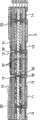
此外,图21示出相关的半导体装置(之二)的剖视图,该半导体装置的特征在于下述构造:将半导体的裸片204、205层叠成棱锥状(裸片之间利用被称作芯片粘接膜(die attach film)的粘接薄膜粘接),利用引线接合将各个裸片的外部端子连接在内插板(interposer)206的外部端子上,并对整体进行树脂封固。该半导体装置是采用了多个器件的半导体装置,而且是能够使器件的安装面积小型化的封装技术,是在移动电话机中广泛使用的三维安装型半导体装置之一。In addition, FIG. 21 shows a cross-sectional view of a related semiconductor device (No. 2), which is characterized by the following structure: the
此外,图22示出专利文献1(日本特开2006-190834号公报)中所记载的半导体装置(之三)的剖视图,是一种三维安装型半导体装置,其特征在于,使外型尺寸不同的第一半导体芯片301和第二半导体302的外部端子(焊盘304)彼此面对并利用凸点303使彼此连接,并且,利用凸点303将在中心部设有孔309的内插板(柔性电路板306)和位于外形尺寸较大一方的半导体芯片(在图中为301)的外周部的外部端子(焊盘304)彼此连接,在所述孔309中收纳有外形尺寸较小一方的半导体芯片(在图22中为302)。In addition, FIG. 22 shows a cross-sectional view of the semiconductor device (Part 3) described in Patent Document 1 (Japanese Patent Laid-Open No. 2006-190834), which is a three-dimensional mounting semiconductor device characterized in that the external dimensions are different. The external terminals (pads 304) of the
此外,图23示出专利文献2(日本特开2007-188921号公报)所记载的半导体装置(之四)的剖视图,是一种三维安装型半导体装置,其特征在于,采用使刚性配线板402和柔性配线板403合成一体而成的内插板,在刚性配线板402的局部的两面安装半导体元件(LSI401),将柔性配线板403的局部折弯,并将柔性板403固定于一方的LSI 401的背面侧(外部端子面的相反面侧)。In addition, FIG. 23 shows a cross-sectional view of a semiconductor device (No. 4) described in Patent Document 2 (Japanese Patent Application Laid-Open No. 2007-188921), which is a three-dimensional mounting semiconductor device characterized in that a rigid wiring board is used. 402 and the
发明想要解决的课题:The problem that the invention wants to solve:
关于图20所示的半导体装置(之一)的构造,形成为在运算处理器封装101的周围二维地排列安装了多个DRAM封装102和多个无源部件103(电阻器、电容器、电感器等)而成的构造(采用了所谓的表面装配技术(SMT)的构造),上述的运算处理器和多个DRAM的安装总面积变大,存在难以使应用该半导体装置的电子设备小型化的课题。而且,如果运算处理器和DRAM的工作时钟频率变高(例如100MHz以上),则在图20所示的构造中,运算处理器与DRAM之间的配线距离长,因此存在信号延迟的问题变得显著、而且信号损失变大从而引起工作不良的课题。此外,在为了缩小半导体装置的外形尺寸、以及为了缩短器件之间的配线距离而在多个器件中采用裸片的情况下,由于将半导体的裸片作为KGD(确好芯片,Known GoodDie)而获得的情况是不可能的或者非常困难,所以存在半导体的组装成品率变低、制造成本变高的课题。Regarding the structure of the semiconductor device (one) shown in FIG. 20, a plurality of
此外,如果采用图21所示的芯片堆叠(chip stack)型半导体装置(之二)的构造制成三维安装了运算处理器(裸片)204和存储器(裸片)205的半导体装置,则其构造成为裸片彼此之间隔着薄粘接层207而接触的构造。例如在运算处理器采用三维图像处理器且存储器采用DRAM的情况下,由于三维图像处理器的发热量大、一般为大约5W以上,因此存在从处理器产生的热直接传递到DRAM、导致DRAM的温度为DRAM的工作保证温度(一般在大约70~80℃以下)以上从而半导体装置无法工作的课题。In addition, if a semiconductor device in which an arithmetic processor (die) 204 and a memory (die) 205 are three-dimensionally mounted using the structure of the chip stack (chip stack) type semiconductor device (Part 2) shown in FIG. The structure has a structure in which dies are in contact with each other through a thin
此外,在图22所示的专利文献1所记载的半导体装置(之三)中形成为如下的构造:使外型尺寸不同的半导体芯片(在图中为301和302)的外部端子(焊盘304)彼此相对并利用凸点303使彼此的外部端子连接,并且,使在中心部设有孔309的内插板(柔性电路板306)和位于外形尺寸较大一方的半导体芯片(在图中为301)的外周部的外部端子(焊盘304)连接,并将外形尺寸较小一方的半导体芯片(在图中为302)收纳于设在内插板306的中心的孔309中。但是,能够实现本构造的多个半导体芯片被互相限定成预先对外部端子的布局进行专门设计的半导体芯片,存在半导体装置的设计自由度低的课题。而且,由于需要专门设计半导体芯片,因此存在需要较长的开发时间、制造成本变高、存储器容量无法根据顾客的需求自由变更的课题。再进一步,由于难以将电阻器、电容器、电感器等多个无源部件安装在半导体芯片(特别是存储器芯片)的附近,因此存在难以使由高速的运算处理器和高速的DRAM等存储器组合而成的半导体装置工作的课题。In addition, in the semiconductor device (third) described in
此外,在图23所示的专利文献2所记载的半导体装置(之四)中形成为如下的构造:采用使刚性配线板402和柔性配线板403合成一体而成的内插板,在刚性配线板402的局部的两面安装半导体元件(LSI 401),将柔性配线板403的局部折弯,并将柔性板403固定于一方的LSI 401的背面侧(外部端子面的相反面侧)。但是,存在最初使刚性配线板402和柔性配线板403合成一体而成的内插板的制造成本高的课题。而且,在安装于内插板的器件的外形大的情况下或是安装的器件有多个的情况下,存在内插板的面积变大、板的翘曲变大、容易招致安装不良的课题。此外,还考虑了为了改善上述情况而加厚内插板的方法,但是这样的话则存在半导体装置的厚度增加的课题。Furthermore, in the semiconductor device (Part 4) described in
此外,与上述的技术相关,不论使用存储器件还是不使用存储器件,当在电路板、电子设备中使用例如以时钟频率超过数百MHz那样的高速来工作的运算处理器的情况下,如果运算处理器以高速进行开关(switching)(工作的ON、OFF),则例如图24所示,存在因存在于从直流电源505到器件的配线、以及印刷电路板的过孔(via)、通孔中的寄生电感(L)而引起向器件供给的直流电压V瞬时降低(变动;ΔV)、引起工作不良的课题。In addition, in connection with the above-mentioned technology, regardless of whether a memory device is used or not, when an arithmetic processor operating at a high speed such as a clock frequency exceeding several hundred MHz is used in a circuit board or an electronic device, if the operation If the processor performs switching (switching) (operational ON, OFF) at high speed, for example, as shown in FIG. The parasitic inductance (L) in the hole causes an instantaneous drop (fluctuation; ΔV) of the DC voltage V supplied to the device, causing a problem of malfunction.
图24示出将以上升时间t1高速地开关的运算处理器504安装于印刷电路板507的情况下的、向运算处理器504供给的直流电压(V)的变动(ΔV)。在图24中,在印刷电路板507上并未安装对直流电压V的变动(ΔV)进行抑制或者补偿的去耦电容器。图25示出图24的等价电路。如果运算处理器504以高速进行开关,则由于存在于直流电源和运算处理器504之间的配线、或印刷电路板507的过孔、通孔506中的寄生电感L(=L1+L2+L3+L4+L5+L6),向运算处理器504供给的直流电压V会发生变动(ΔV)。此处,直流电压的变动量ΔV以(1)式表示。L的符号为-是因为感应电动势以抵消瞬时产生的电流i的方式产生。FIG. 24 shows variation (ΔV) of the DC voltage (V) supplied to the arithmetic processor 504 when the arithmetic processor 504 switching at high speed with the rise time t1 is mounted on the printed circuit board 507 . In FIG. 24 , a decoupling capacitor for suppressing or compensating for a variation (ΔV) of the DC voltage V is not mounted on the printed circuit board 507 . FIG. 25 shows an equivalent circuit of FIG. 24 . If the arithmetic processor 504 performs switching at high speed, due to the wiring existing between the DC power supply and the arithmetic processor 504, or the via hole of the printed circuit board 507, the parasitic inductance L(=L1+L2+ L3+L4+L5+L6), the DC voltage V supplied to the arithmetic processor 504 fluctuates (ΔV). Here, the fluctuation amount ΔV of the DC voltage is represented by the formula (1). The sign of L is - because the induced electromotive force is generated in a way that cancels the instantaneously generated current i.
ΔV=-L×di/dt......(1)ΔV=-L×di/dt...(1)
因此,存在于配线501、502、503、过孔、通孔506中的寄生电感、和电流的时间变动率(di/dt)越大,则电压变动量ΔV越大。若时钟频率变高,则上升时间t1变短,因此,根据(1)式可知电压变动量ΔV变得更大。而且,除此之外,近年来,在运算处理器504中,为了减少耗电量,正在推进输入电压V的低电压化(例如从3.3V向1.8V),电压变动率(ΔV/V)有越来越大的倾向,导致ΔV/V超过运算处理器的工作规范允许值(例如一般为大约5%)。虽然只要开关电源能够对该电压的变动进行补偿即可,但由于通过开关电源进行补偿需要100ns~数十μs的时间,所以无法追随以高速进行开关(数百ps~1ns)的器件的电压变动。Therefore, the larger the parasitic inductance existing in the wirings 501, 502, 503, the via hole, and the through hole 506, and the time variation rate (di/dt) of the current, the larger the voltage variation ΔV. As the clock frequency becomes higher, the rise time t1 becomes shorter, and therefore, from the formula (1), it can be seen that the voltage fluctuation amount ΔV becomes larger. In addition, in recent years, in order to reduce power consumption in the arithmetic processor 504, the input voltage V has been lowered (for example, from 3.3V to 1.8V), and the voltage fluctuation rate (ΔV/V) There is an increasing tendency, causing ΔV/V to exceed the value allowed by the operating specification of the operational processor (eg, typically about 5%). As long as the switching power supply can compensate for this voltage fluctuation, it takes 100 ns to tens of μs to compensate for the switching power supply, so it cannot follow the voltage fluctuation of devices that switch at high speed (hundreds of ps to 1 ns). .
因此,为了防止由这种电压变动导致的误操作,如图26所示,在运算处理器604的电源线-地(接地)线之间并联地连接有所谓的去耦电容器607。去耦电容器607具有以下两个效果:使从运算处理器604产生的高速开关信号分流(bypath)而缩短高速信号的路径,从而使寄生电感L变小(其结果是,使ΔV=-L×di/dt变小)(效果1);通过从去耦电容器607供给电荷(放电)而对在高速开关时暂时下降的电压进行补偿(效果2)。根据(1)式,为了缩小ΔV,只要使存在于高速信号的路径中的电感L(存在于配线、过孔、通孔中的L等)最小即可,一般情况下,为了使该L最小,如图26所示,将去耦电容器607安装于运算处理器604的正侧方或者隔着印刷电路板608安装于运算处理器604的正下方。其结果是,基于去耦电容器607的效果1和效果2,向运算处理器604供给的直流电压的变动ΔV降低。Therefore, in order to prevent malfunctions caused by such voltage fluctuations, a so-called
图27示出图26的等价电路。基于去耦电容器(在图27中简记为DCC)的效果1和效果2,向运算处理器供给的直流电压的变动ΔV如图27右上部的曲线图中的虚线所示那样降低。但是,一般情况下,为了抑制这种直流电压的变动而采用的去耦电容器的数量多,安装占用面积大,存在印刷电路板大面积化和随之而来的成本变高的课题。而且,如果去耦电容器与运算处理器之间的配线距离长,则存在于配线路径中的寄生电感变大,存在无法防止瞬时的电压降低、无法实现半导体装置的稳定的工作的课题。即,去耦电容器与运算处理器之间的配线距离越短越能够实现工作稳定的半导体装置。FIG. 27 shows an equivalent circuit of FIG. 26 . Due to the
发明内容Contents of the invention
本发明就是鉴于以上的课题而做出的,其目的在于一种如下的三维安装型半导体装置及其制造方法:该三维安装型半导体装置是组合了运算处理器、多个存储器件、多个无源部件等多个器件而成的半导体装置,并且是小型薄型的,即便是在采用高速工作的处理器和存储器的情况下也能够工作,散热特性也好,能够不受处理器的耗电量的影响地自由地选择处理器,组装成品率高,且安装可靠性高,成本低。The present invention has been made in view of the above problems, and its object is a three-dimensional mounting type semiconductor device that combines an arithmetic processor, a plurality of memory devices, a plurality of wireless devices, and a method for manufacturing the same. A semiconductor device composed of multiple components such as source parts, and is small and thin, can work even with a high-speed processor and memory, and has good heat dissipation characteristics, and can not be affected by the power consumption of the processor. The processor can be freely selected without influence, the assembly yield is high, and the installation reliability is high, and the cost is low.
此外,本发明的目的在于提供一种由于搭载这样的三维安装型半导体装置而外形面积和体积进一步变小、其结果是能够实现更低成本的印刷电路板及电子设备。Furthermore, an object of the present invention is to provide a printed circuit board and an electronic device that can further reduce the external area and volume by mounting such a three-dimensionally mounted semiconductor device, resulting in a lower cost.
用于解决课题的手段:Means used to solve the problem:
(1)为了达成上述目的,本发明的第一观点所涉及的半导体装置包括:一个柔性电路板,该柔性电路板在第一面设有第一外部电极,在第二面设有第二外部电极和第三外部电极,并且该柔性电路板具有至少两层以上的配线层;多个存储器件;多个无源部件,该无源部件包含电阻器、电容器以及电感器中的至少一种以上;支承体,该支承体设有收纳所述多个存储器件和所述多个无源部件的至少一个以上的槽;以及一个运算处理器,其特征在于,(1) In order to achieve the above object, the semiconductor device according to the first aspect of the present invention includes: a flexible circuit board provided with a first external electrode on a first surface and a second external electrode on a second surface. electrode and a third external electrode, and the flexible circuit board has at least two or more wiring layers; a plurality of storage devices; a plurality of passive components, the passive components including at least one of resistors, capacitors and inductors The above; a support body, the support body is provided with at least one or more slots for accommodating the plurality of storage devices and the plurality of passive components; and an arithmetic processor, characterized in that,
所述柔性电路板具有比所述支承体的面积大的面积,所述多个存储器件和所述多个无源部件平面安装于所述柔性电路板的第一面上并与所述第一面的第一外部电极电连接,并且,所述无源部件安装在所述存储器件的附近,所述支承体以包围所述多个存储器件和所述多个无源部件的方式粘接于所述柔性电路板的第一面上,或者与设在第一面上的第一外部电极电连接,该多个存储器件和该无源部件被收纳在该支承体的槽的内侧,所述柔性电路板沿着所述支承体的外周被折弯,并至少包裹所述支承体的一个以上的侧面和该支承体的表面中的形成有槽的面的表里相反侧的面的至少一部分,该柔性电路板粘接于所述支承体的表面的至少一部分上,在安装有所述多个存储器件和所述无源部件的所述第一外部电极的表里相反侧的第二面上具有所述柔性电路板的第二外部电极,所述运算处理器与所述第二外部电极电连接,所述运算处理器的外部端子面以隔着所述柔性电路板而与所述多个存储器件的外部端子面及多个无源部件彼此面对的方式安装,在所述支承体的表面中的形成有槽的面的表里相反侧的面上具有所述柔性电路板的第三外部电极,在所述第三外部电极上形成有钎料凸点,当将所述钎料凸点定义为下面时,所述运算处理器安装在最上面。The flexible circuit board has an area larger than that of the supporting body, and the plurality of storage devices and the plurality of passive components are planarly mounted on the first surface of the flexible circuit board and connected to the first surface of the flexible circuit board. The first external electrode on the surface is electrically connected, and the passive component is installed in the vicinity of the storage device, and the support body is bonded to the storage device and the passive component in such a manner as to surround the plurality of storage devices and the plurality of passive components. The first surface of the flexible circuit board is electrically connected to the first external electrode provided on the first surface, the plurality of storage devices and the passive components are accommodated inside the groove of the support body, the The flexible circuit board is bent along the outer periphery of the support body, and wraps at least one or more side surfaces of the support body and at least a part of the surface on the opposite side of the surface on which the groove is formed on the surface of the support body. , the flexible circuit board is bonded to at least a part of the surface of the support body, on the second surface on the opposite side of the first external electrode on which the plurality of storage devices and the passive components are mounted. There is a second external electrode of the flexible circuit board on it, and the operation processor is electrically connected to the second external electrode, and the external terminal surface of the operation processor is connected to the multiple terminals via the flexible circuit board. The external terminal surface of a memory device and a plurality of passive components are mounted in such a manner that they face each other, and the first surface of the flexible circuit board is provided on the surface of the surface of the support body opposite to the surface on which the groove is formed. Three external electrodes, a solder bump is formed on the third external electrode, and when the solder bump is defined as the bottom, the arithmetic processor is mounted on the uppermost.
根据该发明,由于是如下的三维安装构造:多个存储器件和多个无源部件平面安装于柔性电路板的一方的面上并电连接,运算处理器与安装有多个存储器件和多个无源部件的面的表里相反侧的面电连接,运算处理器的外部端子面以隔着柔性电路板而与多个存储器件的外部端子面及多个无源部件彼此面对的方式安装,因此,能够实现采用多个器件的半导体装置,且能够实现小型的半导体装置,并且,由于多个存储器件和多个无源部件平面安装于柔性电路板的同一面上,因此能够实现薄型的半导体装置,并且由于能够缩短运算处理器与多个存储器件之间的配线距离,因此,即便是在所使用的器件的工作频率为高速(例如大约100MHz以上)的情况下也能够减少信号延迟和信号损失,能够实现稳定的工作。According to this invention, due to the following three-dimensional mounting structure: a plurality of storage devices and a plurality of passive components are mounted on one side of the flexible circuit board and electrically connected, and the arithmetic processor and the plurality of storage devices and a plurality of The surface on the opposite side of the surface of the passive component is electrically connected, and the external terminal surface of the arithmetic processor is mounted so that the external terminal surface of the plurality of memory devices and the plurality of passive components face each other through the flexible circuit board. , therefore, it is possible to realize a semiconductor device using a plurality of devices, and a small semiconductor device can be realized, and since a plurality of memory devices and a plurality of passive components are planarly mounted on the same surface of a flexible circuit board, it is possible to realize a thin A semiconductor device, and since the wiring distance between an arithmetic processor and a plurality of memory devices can be shortened, signal delay can be reduced even when the operating frequency of the device used is high-speed (for example, about 100 MHz or higher) and signal loss, enabling stable work.
并且,根据本发明,即便是在运算处理器的耗电量大的情况下,也由于运算处理器位于半导体装置的最上面,因此是容易散热的构造,其结果是,即便运算处理器发热也能够抑制相邻接的存储器件的温度上升,能够容易地将环境温度保持在存储器件的工作保证温度以下。此外,根据该发明,由于多个无源部件(电容器、电阻器等)安装在运算处理器和存储器件的附近,因此即便是在所使用的器件的工作频率为例如大约100MHz以上的高速的情况下也能够有效地降低高速信号传播中的以开关噪声为首的各种噪声,能够实现半导体装置的稳定的工作。此外,根据该发明,由于是利用设有槽的支承体包围多个存储器件和多个无源部件并利用柔性电路板包裹支承体的周围,并且将半导体装置的外部电极设在支承体的表面中的形成有槽的面的表里相反侧的面(该侧为平坦的面)的构造,因此能够获得平坦性良好且安装成品率高的半导体装置。Moreover, according to the present invention, even if the power consumption of the arithmetic processor is large, since the arithmetic processor is located on the top of the semiconductor device, it is a structure that is easy to dissipate heat. As a result, even if the arithmetic processor generates heat, The temperature rise of the adjacent memory device can be suppressed, and the ambient temperature can be easily kept below the guaranteed operation temperature of the memory device. Furthermore, according to this invention, since a plurality of passive components (capacitors, resistors, etc.) It is also possible to effectively reduce various noises such as switching noise in high-speed signal propagation, and to achieve stable operation of the semiconductor device. In addition, according to this invention, since a plurality of storage devices and a plurality of passive components are surrounded by a support body provided with grooves, and the periphery of the support body is wrapped with a flexible circuit board, and the external electrodes of the semiconductor device are provided on the surface of the support body Because of the structure of the surface opposite to the surface on which the groove is formed (this side is a flat surface), a semiconductor device with good flatness and high mounting yield can be obtained.
(2)本发明的半导体装置,在上述第一观点所涉及的半导体装置中,构成为所述运算处理器的面积比所述多个存储器件和所述多个无源部件的合计的面积大。(2) In the semiconductor device according to the present invention, in the semiconductor device according to the above-mentioned first aspect, the area of the arithmetic processor is larger than the total area of the plurality of memory devices and the plurality of passive components. .
在上述第一观点所涉及的半导体装置中,运算处理器搭载在最上面,根据本发明,如果以形成本发明的半导体装置的核心的运算处理器(由于在半导体装置的设计的最初就决定运算处理器的规范,因此定义为核心)的面积作为基础,以多个存储器件和多个无源部件的合计的面积比运算处理器的面积小的方式设计半导体装置的话,则能够将半导体装置整体的外形尺寸抑制在最小限度。In the semiconductor device related to the above-mentioned first viewpoint, the arithmetic processor is mounted on the top. The specifications of the processor, so it is defined as the area of the core), and if the semiconductor device is designed so that the total area of the multiple memory devices and the multiple passive components is smaller than the area of the arithmetic processor, the overall semiconductor device can be The external dimensions are kept to a minimum.
(3)为了达成上述目的,本发明的第二观点所涉及的半导体装置包括:一个柔性电路板,该柔性电路板在第一面设有第一外部电极,在第二面设有第二外部电极和第三外部电极,并且该柔性电路板具有至少两层以上的配线层;多个无源部件,该无源部件包含电阻器、电容器以及电感器中的至少一种以上;支承体,该支承体设有收纳所述多个无源部件的至少一个以上的槽;以及一个运算处理器,其特征在于,(3) In order to achieve the above object, the semiconductor device according to the second aspect of the present invention includes: a flexible circuit board provided with a first external electrode on a first surface and a second external electrode on a second surface. An electrode and a third external electrode, and the flexible circuit board has at least two or more wiring layers; a plurality of passive components, the passive components include at least one of resistors, capacitors, and inductors; a support body, The supporting body is provided with at least one groove for accommodating the plurality of passive components; and an arithmetic processor, characterized in that,
所述柔性电路板具有比所述支承体的面积大的面积,所述多个无源部件平面安装于所述柔性电路板的第一面上并与所述第一面的第一外部电极电连接,所述支承体以包围所述多个无源部件的方式粘接于所述柔性电路板的第一面上,或者与设在第一面上的第一外部电极电连接,所述多个无源部件被收纳在所述支承体的槽的内侧,所述柔性电路板沿着所述支承体的外周被折弯,并至少包裹所述支承体的一个以上的侧面和该支承体的表面中的形成有槽的面的表里相反侧的面的至少一部分,该柔性电路板粘接于所述支承体的表面的至少一部分上,在安装有所述多个无源部件的所述第一外部电极的表里相反侧的第二面上具有所述柔性电路板的第二外部电极,所述运算处理器与所述第二外部电极电连接,所述运算处理器的外部端子面以隔着所述柔性电路板而与所述多个无源部件彼此面对的方式安装,在所述支承体的表面中的形成有槽的面的表里相反侧的面上具有所述柔性电路板的第三外部电极,在所述第三外部电极上形成有钎料凸点,当将所述钎料凸点定义为下面时,所述运算处理器安装在最上面。The flexible circuit board has an area larger than that of the supporting body, and the plurality of passive components are planarly mounted on the first surface of the flexible circuit board and electrically connected to the first external electrodes of the first surface. Connecting, the support body is bonded to the first surface of the flexible circuit board in a manner surrounding the multiple passive components, or is electrically connected to the first external electrode provided on the first surface, the multiple two passive components are accommodated inside the groove of the support body, the flexible circuit board is bent along the outer periphery of the support body, and wraps at least one or more side surfaces of the support body and the support body At least a part of the surface on the opposite side of the surface on which the grooves are formed, the flexible circuit board is bonded to at least a part of the surface of the support body, and the flexible circuit board is mounted on the plurality of passive components. There is a second external electrode of the flexible circuit board on the second surface of the opposite side of the first external electrode, the operation processor is electrically connected to the second external electrode, and the external terminal surface of the operation processor is The flexible circuit board is installed so as to face each other with the plurality of passive components across the flexible circuit board, and the flexible circuit board is provided on a surface opposite to a surface in which grooves are formed on the surface of the support body. The third external electrode of the circuit board has a solder bump formed on the third external electrode, and when the solder bump is defined as the bottom, the arithmetic processor is mounted on the uppermost.
根据该发明,由于能够将原本安装于运算处理器的正侧方、或是隔着印刷电路板安装在运算处理器的相反面上的主要是多个去耦电容器(也称为旁路电容器)放入半导体装置中,因此能够实现印刷电路板的小型化。而且,特别是在本发明中内插板采用配线层数为两层以上的柔性电路板,与以往的刚性电路板(厚度:大约0.8mm~1.0mm)相比,柔性电路板的厚度薄、通常为大约0.09mm~0.15mm,能够缩小存在于基板内部的配线、过孔、通孔等中的寄生电感,因此具有能够进一步降低高频信号的噪声的优点。According to this invention, since it is possible to install a plurality of decoupling capacitors (also called bypass capacitors) that are originally installed on the front side of the arithmetic processor or on the opposite side of the arithmetic processor through a printed circuit board, Since it is incorporated into a semiconductor device, the miniaturization of the printed circuit board can be realized. Furthermore, especially in the present invention, the interposer uses a flexible circuit board with two or more wiring layers, and the thickness of the flexible circuit board is thinner than that of conventional rigid circuit boards (thickness: about 0.8 mm to 1.0 mm). , usually about 0.09 mm ~ 0.15 mm, can reduce the parasitic inductance existing in the wiring, vias, through holes, etc. inside the substrate, so it has the advantage of further reducing the noise of high-frequency signals.
此外,由于能够将去耦电容器配置在印刷电路板(主板)与运算处理器之间、且在运算处理器的电源端子和接地端子的附近,因此,与以往的安装形态相比能够缩小存在于运算处理器与去耦电容器之间的寄生电感,能够缩小运算处理器在开关操作时所产生的电压变动,能够获得工作稳定的半导体装置。In addition, since the decoupling capacitor can be arranged between the printed circuit board (main board) and the arithmetic processor, and in the vicinity of the power supply terminal and the ground terminal of the arithmetic processor, it is possible to reduce the existing The parasitic inductance between the arithmetic processor and the decoupling capacitor can reduce the voltage variation generated during the switching operation of the arithmetic processor, and a semiconductor device with stable operation can be obtained.
(4)为了达成上述目的,本发明的第三观点所涉及的半导体装置包括:一个柔性电路板,该柔性电路板在第一面设有第一外部电极,在第二面设有第二外部电极和第三外部电极,并且该柔性电路板具有至少两层以上的配线层;多个存储器件;支承体,该支承体设有收纳所述多个存储器件的至少一个以上的槽;以及一个运算处理器,其特征在于,(4) In order to achieve the above object, the semiconductor device according to the third aspect of the present invention includes: a flexible circuit board provided with a first external electrode on a first surface and a second external electrode on a second surface. An electrode and a third external electrode, and the flexible circuit board has at least two or more wiring layers; a plurality of memory devices; a support body provided with at least one or more grooves for receiving the plurality of memory devices; and An arithmetic processor characterized in that,
所述柔性电路板具有比所述支承体的面积大的面积,所述多个存储器件平面安装于所述柔性电路板的第一面上并与所述第一面的第一外部电极电连接,所述支承体以包围所述多个存储器件的方式粘接于所述柔性电路板的第一面上,或者与设在第一面上的第一外部电极电连接,所述多个存储器件被收纳在所述支承体的槽的内侧,所述柔性电路板沿着所述支承体的外周被折弯,并至少包裹所述支承体的一个以上的侧面和该支承体的表面中的形成有槽的面的表里相反侧的面的至少一部分,该柔性电路板粘接于所述支承体的表面的至少一部分上,在安装有所述多个存储器件的所述第一外部电极的表里相反侧的第二面上具有所述柔性电路板的第二外部电极,所述运算处理器与所述第二外部电极电连接,所述运算处理器的外部端子面以隔着所述柔性电路板而与所述多个存储器件的外部端子面彼此面对的方式安装,在所述支承体的表面中的形成有槽的面的表里相反侧的面上具有所述柔性电路板的第三外部电极,在所述第三外部电极上形成有钎料凸点,当将所述钎料凸点定义为下面时,所述运算处理器安装在最上面。The flexible circuit board has an area larger than that of the supporting body, and the plurality of memory devices are planarly mounted on the first surface of the flexible circuit board and electrically connected to the first external electrodes on the first surface , the support body is bonded to the first surface of the flexible circuit board in a manner to surround the plurality of memory devices, or is electrically connected to the first external electrode provided on the first surface, and the plurality of memory devices The parts are accommodated inside the groove of the support body, the flexible circuit board is bent along the outer periphery of the support body, and wraps at least one or more side surfaces of the support body and the surface of the support body At least a part of the surface opposite to the surface on which the groove is formed, the flexible circuit board is bonded to at least a part of the surface of the support body, and the first external electrode on which the plurality of memory devices are mounted There is a second external electrode of the flexible circuit board on the second surface on the opposite side of the front and back, the operation processor is electrically connected to the second external electrode, and the external terminal surface of the operation processor is separated by the The flexible circuit board is installed in such a manner that the external terminal surfaces of the plurality of memory devices face each other, and the flexible circuit board is provided on the surface of the surface of the support body opposite to the surface on which the groove is formed. A third external electrode of the board on which a solder bump is formed, and when the solder bump is defined as the lower side, the arithmetic processor is mounted uppermost.
该结构与上述第一观点所涉及的半导体装置类似,但是,在半导体装置内部未安装多个无源部件这点不同。例如,在半导体装置被面向移动设备来使用且运算处理器和多个存储器件的工作频率在大约100MHz以下的情况等、即使在半导体装置内部没有无源部件半导体装置也能够单独工作的情况,可以是该第三观点所涉及的结构。如果不在半导体装置内部安装多个无源部件的话,则有能够使半导体装置相应地小型化的优点。而且,还存在基于使用者的情况而想要在以后将无源部件安装于主板上的半导体装置的周围的情况,因此,在这种情况下,该第三观点的结构是优选的。This structure is similar to the semiconductor device according to the above-mentioned first viewpoint, but differs in that a plurality of passive components are not mounted inside the semiconductor device. For example, in the case where the semiconductor device is used for mobile devices and the operation frequency of the arithmetic processor and a plurality of memory devices is about 100 MHz or less, the semiconductor device can operate independently without passive components inside the semiconductor device. is the structure involved in this third viewpoint. There is an advantage that the semiconductor device can be miniaturized accordingly if a large number of passive components are not mounted inside the semiconductor device. Furthermore, there may be cases where the user wants to mount passive components around the semiconductor device on the main board later, so in such a case, the configuration of the third viewpoint is preferable.
(5)本发明的半导体装置,在上述第一观点~第三观点所涉及的半导体装置中,构成为所述运算处理器具有散热器和热沉中的至少某一个。(5) In the semiconductor device according to the present invention, in the semiconductor device according to the above-mentioned first aspect to the third aspect, the arithmetic processor includes at least one of a heat sink and a heat sink.
根据该发明,能够进一步提高半导体装置的冷却效果,能够进一步抑制半导体装置的温度上升,能够实现工作稳定的半导体装置。According to this invention, the cooling effect of the semiconductor device can be further improved, the temperature rise of the semiconductor device can be further suppressed, and a semiconductor device with stable operation can be realized.
(6)本发明的半导体装置,在上述第一~第三观点所涉及的半导体装置中,构成为所述运算处理器和多个存储器件、或者所述运算处理器是BGA(球栅阵列,Ball Grid Array)类型的封装。(6) In the semiconductor device according to the present invention, in the semiconductor device according to the above-mentioned first to third aspects, the arithmetic processor and a plurality of memory devices are configured, or the arithmetic processor is a BGA (Ball Grid Array, Ball Grid Array) type encapsulation.
根据该发明,由于多个存储器件和一个运算处理器、或者一个运算处理器不是裸片,而是经过质量保证的BGA类型的封装,因此能够获得高组装成品率的半导体装置。此外,作为经过质量保证的封装,除了BGA类型,还有TSOP(薄型小尺寸封装,Thin Small OutlinePackage)、SOP(小尺寸封装,Small Outline Package)、GFP(方形扁平封装,Quad Flat Package)以及TCP(带载封装,Tape CarrierPackage)类型等各种形态的封装,其中,BGA类型的封装尤其小型,因此能够通过采用BGA类型的封装使半导体装置更加小型化。另外,所谓BGA类型的封装有例如μ(微,Micro)-BGA、FBGA(精确栅距BGA,Fine pitch BGA)、晶圆级封装(Wafer Level CSP)等,也包含其他的BGA类型的封装,是指作为外部端子具有钎料球(或者钎料凸点)的封装。According to this invention, since a plurality of memory devices and an arithmetic processor, or an arithmetic processor are not bare chips but are packaged in a quality-guaranteed BGA type, it is possible to obtain a semiconductor device with a high assembly yield. In addition, as quality-guaranteed packages, in addition to BGA types, there are TSOP (Thin Small Outline Package), SOP (Small Outline Package), GFP (Quad Flat Package), and TCP (Tape Carrier Package, Tape Carrier Package) types and other types of packages, among which, the BGA type package is particularly small, so the semiconductor device can be further miniaturized by adopting the BGA type package. In addition, the so-called BGA type packages include μ (micro, Micro)-BGA, FBGA (precise grid pitch BGA, Fine pitch BGA), wafer level package (Wafer Level CSP), etc., and also include other BGA type packages, Refers to a package that has solder balls (or solder bumps) as external terminals.
(7)本发明的半导体装置,在上述第一~第三观点所涉及的半导体装置(除了上述(3)的发明之外)中,所述多个存储器件为DRAM(动态随机存取存储器,Dynamic Random Access Memory),且所述运算处理器是图像处理器。(7) In the semiconductor device of the present invention, in the semiconductor device according to the above-mentioned first to third aspects (in addition to the invention of (3) above), the plurality of storage devices are DRAMs (Dynamic Random Access Memory, Dynamic Random Access Memory), and the operation processor is an image processor.
根据该发明,由于存储器件采用多个DRAM,运算处理器采用图像处理器,能够高速地处理大容量的信息,因此能够实现能够在画面上映出高精细的图像和三维动画图像的小型的图像处理模块。According to this invention, since a plurality of DRAMs are used as a storage device, and an image processor is used as an arithmetic processor, large-capacity information can be processed at high speed, so it is possible to realize compact image processing capable of displaying high-definition images and three-dimensional animation images on the screen. module.
(8)本发明的半导体装置,在上述第一~第三观点所涉及的半导体装置(除了上述(3)的发明之外)中,所述多个存储器件的至少一个是多芯片封装或者彼此层叠而成的层叠封装构造。(8) In the semiconductor device of the present invention, in the semiconductor device according to the above-mentioned first to third aspects (in addition to the invention of (3) above), at least one of the plurality of memory devices is a multi-chip package or mutually Stacked package structure.
根据该发明,由于存储器件中的至少一个采用多芯片封装或者彼此层叠而成的层叠封装(Package on Package)构造,因此能够在相同面积中安装更多的存储器件,能够实现半导体装置的存储器的大容量化。According to this invention, since at least one of the memory devices is structured in a multi-chip package or stacked package (Package on Package), it is possible to mount more memory devices in the same area, and it is possible to realize the memory capacity of the semiconductor device. Larger capacity.
(9)本发明的半导体装置,在上述第一~第三观点所涉及的半导体装置中,构成为所述支承体由金属材料形成,并与所述柔性电路板的地线电连接。(9) In the semiconductor device according to the present invention, in the semiconductor device according to the above first to third aspects, the support body is formed of a metal material and is electrically connected to the ground of the flexible wiring board.
根据该发明,由于支承体采用金属材料,且将该支承体与柔性电路板的地线连接,因此,即便是在支承体采用金属材料的情况下,支承体的电位也不会变得不稳定,而且能够强化半导体装置的地线整体,因此能够实现没有电位变动、或者电位变动少的地线,能够实现半导体装置的稳定的工作。According to this invention, since the supporting body is made of a metal material, and the supporting body is connected to the ground of the flexible circuit board, even if the supporting body is made of a metal material, the potential of the supporting body will not become unstable. , and the entire ground of the semiconductor device can be strengthened, so a ground with no or little potential fluctuation can be realized, and stable operation of the semiconductor device can be realized.
(10)本发明的半导体装置,在上述第一~第三观点所涉及的半导体装置中,构成为所述支承体的至少一部分由42合金、科瓦铁镍钴合金等含Ni的合金、陶瓷以及Si中的任一种材料构成。(10) In the semiconductor device according to the present invention, in the semiconductor device according to the above-mentioned first to third viewpoints, at least a part of the support body is made of Ni-containing alloy such as 42 alloy, Kovar, or ceramics. And any material in Si.
根据该发明,由于支承体的至少一部分由42合金、科瓦铁镍钴合金等含Ni的合金、陶瓷以及Si中的任一种材料构成,这些材料的线膨胀率小,大约为3ppm~5ppm,因此能够防止配置在支承体的槽上的柔性电路板的挠曲和凹凸,能够防止安装在槽之上的柔性电路板上的运算处理器的安装不良。其结果是,能够实现组装成品率高的半导体装置。According to this invention, since at least a part of the support body is made of any one of Ni-containing alloys such as 42 alloys, Kovar alloys, ceramics, and Si, the coefficients of linear expansion of these materials are small, approximately 3 ppm to 5 ppm. Therefore, it is possible to prevent deflection and unevenness of the flexible circuit board disposed on the groove of the support body, and to prevent mounting defects of the arithmetic processor mounted on the flexible circuit board on the groove. As a result, a semiconductor device with a high assembly yield can be realized.
(11)本发明的半导体装置,在上述第一~第三观点所涉及的半导体装置中,构成为所述支承体由设有用于收纳所述多个存储器件和所述多个无源部件的至少一个以上的贯通孔的至少一片以上的板、和一片平板层叠而制成。(11) In the semiconductor device according to the present invention, in the semiconductor device according to the above-mentioned first to third viewpoints, the support body is configured such that the support body is provided with a storage device for accommodating the plurality of memory devices and the plurality of passive components. At least one plate having at least one through hole and one flat plate are laminated.
根据该发明,由于由设有用于收纳多个存储器件和多个无源部件的至少一个以上的贯通孔的至少一片以上的板和一片平板层叠而制成具有槽的支承体,因此,与通过蚀刻或采用金属模在一个平板材料上形成槽的方法相比,能够廉价地制造。而且,由于能够组合多种材料制成支承体,因此,与利用一种材料制成支承体的情况相比较,能够容易地实现支承体所期望的低线膨胀率、轻量、廉价等。According to this invention, since at least one board provided with at least one through-hole for accommodating a plurality of memory devices and a plurality of passive components is stacked with a flat plate to form a support body having a groove, it is different from the It can be manufactured cheaply compared to the method of forming grooves in a flat material by etching or using a metal mold. Furthermore, since the support body can be formed by combining a plurality of materials, it is easier to realize the desired low coefficient of linear expansion, light weight, and low cost of the support body, compared with the case where the support body is formed from a single material.
(12)本发明的半导体装置,在上述(11)的发明所涉及的半导体装置中,所述支承体中的至少设有贯通孔的板的部分由42合金、科瓦铁镍钴合金等含Ni的合金制成。(12) In the semiconductor device of the present invention, in the semiconductor device according to the invention of (11) above, at least the portion of the plate provided with the through hole in the support is made of 42 alloy, Kovar, or the like. Made of Ni alloy.
根据该发明,与柔性电路板粘接或连接的至少设有贯通孔的板的部分由42合金、科瓦铁镍钴合金等含Ni的合金制成,这些材料的线膨胀率小、大约为3ppm~5ppm,因此能够防止配置在支承体的槽上的柔性电路板的挠曲和凹凸,能够防止安装在槽之上的柔性电路板上的运算处理器的安装不良。其结果是,能够实现组装成品率高的半导体装置。而且,由于与柔性电路板粘接或连接的至少设有贯通孔的板部分是42合金、科瓦铁镍钴合金等含有Ni的合金,因此能够将其与柔性电路板的地线连接来强化地线。其结果是,能够实现地线电位没有变动、或者电位变动少的地线,能够实现半导体装置的稳定的工作。According to this invention, at least the part of the plate provided with the through hole that is bonded or connected with the flexible circuit board is made of Ni-containing alloys such as 42 alloy, Kovar, etc., and the linear expansion rate of these materials is small, about 3ppm to 5ppm, therefore, it is possible to prevent warping and unevenness of the flexible printed circuit board arranged on the groove of the support body, and to prevent mounting defects of the arithmetic processor mounted on the flexible printed circuit board on the groove. As a result, a semiconductor device with a high assembly yield can be realized. Moreover, since at least the part of the board that is bonded or connected to the flexible circuit board is provided with a through hole is an alloy containing Ni such as 42 alloy, Kovar, etc., it can be connected to the ground wire of the flexible circuit board to strengthen ground wire. As a result, it is possible to realize a ground with little or no potential fluctuation in the ground potential, and to achieve stable operation of the semiconductor device.
(13)本发明的半导体装置,在上述(11)的发明所涉及的半导体装置中,构成为,构成所述支承体的材料中的至少所述一片平板由铝、铝合金、钛、钛合金、陶瓷、以及Si中的任一种材料制成。(13) In the semiconductor device of the present invention, in the semiconductor device according to the invention of (11) above, at least one of the flat plates among the materials constituting the support is made of aluminum, aluminum alloy, titanium, titanium alloy , ceramics, and any one of Si materials.
根据该发明,由于构成支承体的材料中的至少一片平板由铝、铝合金、钛、钛合金、陶瓷、以及Si中的任一种材料制作,这些材料的比重小,因此能够使支承体轻量化。如果支承体的重量增加,则当将半导体装置二次安装于印刷基板上时,由于半导体装置的自重导致外部端子的钎料球的压溃量变大,容易与相邻的钎料球短路,存在安装成品率低的课题,但是,通过采用该结构,能够改善短路不良,能够实现组装成品率高的半导体装置。According to this invention, since at least one flat plate in the material constituting the supporting body is made of any material in aluminum, aluminum alloy, titanium, titanium alloy, ceramics, and Si, the specific gravity of these materials is small, so the supporting body can be made light. Quantify. If the weight of the support body increases, when the semiconductor device is secondarily mounted on the printed circuit board, the amount of crushing of the solder balls of the external terminals due to the self-weight of the semiconductor device increases, and it is easy to short-circuit with the adjacent solder balls, causing Although there is a problem of low mounting yield, by employing this structure, it is possible to improve short-circuit defects and realize a semiconductor device with high assembly yield.
(14)本发明的半导体装置,在上述(11)~(13)的发明所涉及的半导体装置中,构成为,构成所述支承体的层叠的材料至少一部分彼此经由导电性材料或绝缘性材料粘接或连接,或者至少一部分彼此焊接。(14) In the semiconductor device of the present invention, in the semiconductor device according to the inventions (11) to (13) above, at least a part of the stacked materials constituting the support body is configured such that a conductive material or an insulating material is interposed therebetween. Bonded or connected, or at least partially welded to each other.
根据该发明,在构成支承体的设有贯通孔的板和平板中,各自的至少一部分彼此经由导电性材料或绝缘性材料粘接或连接,或者至少一部分彼此焊接,因此,在将柔性电路板折弯并粘接于支承体的周围的工序中,能够实现稳定的形状的支承体(在使柔性电路板粘接的工序中支承体不会分解而散乱),其结果是,能够实现组装成品率高的半导体装置。According to this invention, in the plate and the flat plate provided with the through hole constituting the support body, at least a part of each is bonded or connected to each other via a conductive material or an insulating material, or at least a part of it is welded to each other. In the process of bending and bonding around the support body, a support body with a stable shape can be realized (the support body will not be disassembled and scattered in the process of bonding the flexible circuit board), and as a result, an assembled product can be realized High-efficiency semiconductor devices.
(15)本发明的半导体装置,在上述(11)~(13)的发明所涉及的半导体装置中,构成为,在构成所述支承体的层叠的材料中的一方的材料的表面上形成有突起,在与所述材料彼此重合的另一方的材料上形成有接纳所述突起的贯通孔或槽,层叠的材料彼此在所述突起与所述贯通孔或槽的部分连接。(15) In the semiconductor device of the present invention, in the semiconductor device according to the inventions (11) to (13) above, the surface of one of the laminated materials constituting the support is formed with: As for the protrusion, a through hole or a groove for receiving the protrusion is formed in the other material that overlaps with the above material, and the laminated materials are connected to each other at the portion of the protrusion and the through hole or groove.
根据该发明,由于在构成所述支承体的层叠的材料中的一方的材料的表面上形成有突起,在与所述材料彼此重合的另一方的材料上形成有接纳所述突起的贯通孔或槽,层叠的材料彼此在所述突起与所述贯通孔或槽的部分连接,因此,与(14)同样,能够实现稳定的形状的支承体,且不使用粘接材料和焊接工艺就能够实现支承体,因此能够以比(14)的半导体装置还低的成本制造支承体。According to this invention, since the protrusion is formed on the surface of one material of the laminated materials constituting the support body, a through-hole for receiving the protrusion is formed in the other material overlapping with the material. In the groove, the laminated materials are connected to each other at the portion of the protrusion and the through hole or groove. Therefore, similar to (14), a support body with a stable shape can be realized, and it can be realized without using an adhesive material or a welding process. Therefore, the support body can be manufactured at a lower cost than the semiconductor device of (14).
(16)本发明的半导体装置,在上述第一~第三观点所涉及的半导体装置中,构成为在所述支承体的槽的周围、构成所述支承体的设有贯通孔的板中的所述贯通孔的周围、以及构成所述支承体的一片平板内之中的至少任一个部位设有多个贯通孔。(16) In the semiconductor device according to the present invention, in the semiconductor device according to the above-mentioned first to third viewpoints, in the periphery of the groove of the support body, in the plate provided with the through hole constituting the support body, A plurality of through-holes are provided around the through-hole and at least any one of the flat plates constituting the support.
根据该发明,通过在支承体的槽的周围、构成支承体的设有贯通孔的板中的贯通孔的周围、或构成支承体的一片平板内之中的至少任一个部位设有多个贯通孔,能够减少构成支承体的材料的实质的体积,因此能够减少支承体的重量。其结果是,当将半导体装置二次安装于印刷基板上时,能够抑制因半导体装置的自重导致的外部端子的钎料球的压溃量的增加,能够改善与相邻的钎料球之间的短路不良的课题,能够实现组装成品率高的半导体装置。According to this invention, by providing a plurality of through-holes around the groove of the support body, around the through-holes in the plate with the through-holes constituting the support body, or in at least any one of a flat plate constituting the support body. The holes can reduce the substantial volume of the material constituting the support body, and thus can reduce the weight of the support body. As a result, when the semiconductor device is secondarily mounted on the printed circuit board, the increase in the amount of crushing of the solder balls of the external terminals due to the self-weight of the semiconductor device can be suppressed, and the gap between the solder balls and the adjacent solder balls can be improved. The problem of short-circuit defects can be solved, and semiconductor devices with high assembly yield can be realized.
(17)本发明的半导体装置,在上述第一~第三观点所涉及的半导体装置中,所述存储器件与所述支承体经由导热材料而接触。(17) In the semiconductor device according to the present invention, in the semiconductor device according to the above-mentioned first to third aspects, the memory device and the support are in contact through a heat conductive material.
根据该发明,即便是在存储器件的耗电量大的情况下,也能够经由导热材料使从存储器件产生的热散发到支承体(支承体起到存储器件的热沉的作用),因此能够实现半导体装置的稳定的工作。According to this invention, even when the power consumption of the storage device is large, the heat generated from the storage device can be dissipated to the support through the heat-conducting material (the support functions as a heat sink of the storage device), so it is possible to Stable operation of the semiconductor device is realized.
(18)本发明的半导体装置,在上述第一~第三观点所涉及的半导体装置中,构成为,在所述柔性电路板的第一面的一部分上粘贴有用于与所述支承体的表面粘接的热塑性粘接树脂薄膜或固化处理前的热固性粘接树脂薄膜。(18) In the semiconductor device according to the present invention, in the semiconductor device according to the above-mentioned first to third viewpoints, a portion of the first surface of the flexible circuit board is affixed with a surface for bonding to the support. Bonded thermoplastic adhesive resin film or thermosetting adhesive resin film before curing treatment.
根据该发明,由于在柔性电路板的第一面的一部分上且是粘接于支承体的表面上的区域粘贴有热塑性粘接树脂薄膜或固化处理前的热固性粘接树脂薄膜,因此能够一边对柔性电路板进行加热一边折弯并容易地粘接于支承体的表面上,能够实现组装成品率高的半导体装置。而且,由于粘接材料采用薄膜形态的材料,所以能够使粘接层的厚度大致恒定,能够减小粘接在了支承体的表面上的柔性电路板的表面的凹凸,能够获得平坦性佳的半导体装置,其结果是,当将半导体装置二次安装于印刷基板上时能够获得高安装组装成品率。According to this invention, since a thermoplastic adhesive resin film or a thermosetting adhesive resin film before curing treatment is pasted on a part of the first surface of the flexible circuit board and the area that is bonded to the surface of the support body, it is possible to The flexible wiring board can be easily bonded to the surface of the support while being bent while being heated, and a semiconductor device with high assembly yield can be realized. Moreover, since the adhesive material is in the form of a thin film, the thickness of the adhesive layer can be made substantially constant, and the unevenness of the surface of the flexible circuit board bonded to the surface of the support body can be reduced, and a flat surface with good flatness can be obtained. As a result, when the semiconductor device is secondarily mounted on the printed circuit board, a high mounting and assembling yield can be obtained.
而且,由于采用热塑性粘接树脂薄膜作为粘接层,如果对柔性电路板进行加热则这些材料的弹性率显著变小(几MPa~几十MPa的程度)、变软,因此即便柔性电路板的厚度增加与粘接层相当的量,也能够容易地将柔性电路板折弯,并能够容易地与支承体粘接。此外,通过粘接层采用热固化前(所谓的B阶段状态)的热固性粘接树脂薄膜,与热塑性树脂同样,该材料的弹性率小(一般在100MPa以下),因此即便柔性电路板的厚度增加也能够容易地将柔性电路板折弯,并能够容易地与支承体粘接。Furthermore, since a thermoplastic adhesive resin film is used as an adhesive layer, if the flexible circuit board is heated, the elastic modulus of these materials will be significantly reduced (on the order of several MPa to several tens of MPa) and will become soft, so even the flexible circuit board Even if the thickness is increased by an amount equivalent to that of the adhesive layer, the flexible wiring board can be easily bent and bonded to the support easily. In addition, the thermosetting adhesive resin film before thermosetting (so-called B-stage state) is used for the adhesive layer. Like thermoplastic resin, the elastic modulus of this material is small (generally below 100MPa), so even if the thickness of the flexible circuit board increases The flexible wiring board can also be easily bent and bonded to the support easily.
(19)本发明的半导体装置,在上述第一~第三观点所涉及的半导体装置中,构成为在所述运算处理器上安装有热沉,该热沉是覆盖半导体模块整体的形状。(19) In the semiconductor device according to the present invention, in the semiconductor device according to the above-mentioned first to third aspects, the arithmetic processor is provided with a heat sink having a shape covering the entire semiconductor module.
根据该发明,由于在位于半导体装置的最上面侧的运算处理器安装有热沉,且热沉是覆盖半导体模块整体的形状,因此能够使热沉整体的表面积大,能够实现散热性能佳的半导体装置。According to this invention, since the heat sink is mounted on the arithmetic processor located on the uppermost side of the semiconductor device, and the heat sink has a shape covering the entire semiconductor module, the surface area of the entire heat sink can be increased, and a semiconductor device with good heat dissipation performance can be realized. device.
(20)本发明的半导体装置,在上述第一~第三观点所涉及的半导体装置中,构成为所述柔性电路板中的沿着所述支承体被折弯的区域的配线层数比未被折弯的其他区域的配线层数少。(20) In the semiconductor device according to the present invention, in the semiconductor device according to the above-mentioned first to third aspects, the ratio of the number of wiring layers in the region of the flexible circuit board that is bent along the support body to Other regions that are not bent have fewer wiring layers.
一般情况下,在柔性电路板中,如果配线层数增加,则配线材料(一般为金属材料)的体积增加,因此难以进行将柔性电路板折弯并粘接于支承体的表面的工序(如果柔性电路板的配线层数增加,则折弯时柔性电路板想要返回原来的形状的反力变大,因此难以粘接固定于支承体的表面)。In general, in a flexible circuit board, if the number of wiring layers increases, the volume of the wiring material (generally a metal material) increases, so it is difficult to perform the process of bending the flexible circuit board and bonding it to the surface of the support (If the number of wiring layers of the flexible wiring board increases, the reaction force for the flexible wiring board to return to its original shape when bent becomes large, so it is difficult to adhere and fix it to the surface of the support body).
根据该发明,柔性电路板中的沿着支承体折弯的区域的配线层数比未折弯的其他区域的配线层数少,因此,即便是在柔性电路板为多层配线板的情况下也能够更容易地折弯,能够实现组装成品率高的半导体装置。According to this invention, the number of wiring layers in the area where the flexible circuit board is bent along the support body is smaller than that in other areas that are not bent. Therefore, even if the flexible circuit board is a multilayer wiring board It can be bent more easily even in the case of assembling, and a semiconductor device with a high assembly yield can be realized.
(21)为了达成上述目的,本发明的印刷电路板的特征在于搭载有上述第一~第三观点所涉及的(1)~(20)中的任一半导体装置。(21) In order to achieve the above object, the printed wiring board of the present invention is characterized in that any one of the semiconductor devices in (1) to (20) according to the above first to third viewpoints is mounted.
根据该发明,由于是搭载有本发明的任一半导体装置的印刷电路板,因此能够使外形尺寸比以往的表面装配型的印刷电路板的外形尺寸小。According to this invention, since it is a printed wiring board on which any one of the semiconductor devices of the present invention is mounted, the outer dimensions can be made smaller than those of conventional surface mount type printed wiring boards.
(22)为了达成上述目的,本发明的电子设备的特征在于搭载有上述第一~第三观点所涉及的(1)~(20)中的任一半导体装置。(22) In order to achieve the above object, the electronic device of the present invention is characterized in that any one of the semiconductor devices in (1) to (20) according to the above first to third viewpoints is mounted.
(23)为了达成上述目的,本发明的电子设备的特征在于搭载有上述(21)所涉及的印刷电路板。(23) In order to achieve the above object, the electronic device of the present invention is characterized in that the printed circuit board according to the above (21) is mounted.
根据这些(22)、(23)的发明,由于是搭载有本发明的任一半导体装置或者印刷电路板的电子设备,因此能够实现比搭载有以往的半导体装置或以往的印刷基板的电子设备更小型的电子设备。According to the inventions of (22) and (23), since it is an electronic device equipped with any one of the semiconductor devices or printed circuit boards of the present invention, it is possible to realize a more efficient electronic device than a conventional semiconductor device or a conventional printed circuit board. Small electronic devices.
(24)为了达成上述目的,本发明的第一观点所涉及的半导体装置的制造方法的特征在于,包含以下工序:(a)将多个无源部件安装在柔性电路板的第一面上的工序;(b)将多个存储器件安装在所述柔性电路板的第一面上的工序;(c)以覆盖安装在该柔性电路板的第一面上的所述多个存储器件和所述多个无源部件的方式进行支承体向所述柔性电路板的第一面安装的工序,所述支承体具有用于收纳所述多个存储器件和所述多个无源部件的槽;(d)将所述柔性电路板沿着所述支承体的外周折弯,并至少包裹所述支承体的一个以上的侧面和该支承体的表面中的形成有槽的面的表里相反侧的面的至少一部分,并且将该柔性电路板粘接于所述支承体的表面的至少一部分上的工序;(e)将运算处理器安装在所述柔性电路板的第二外部电极上的工序,所述第二外部电极形成于安装有所述多个存储器件和所述多个无源部件的所述柔性电路板的第一外部电极的表里相反侧的第二面上;以及(f)在粘接于所述支承体的表面中的形成有槽的面的表里相反侧的面上的所述柔性电路板的第三外部电极上形成钎料凸点的工序。另外,以下的制造方法的发明是分别与上述第一~第三观点所涉及的半导体装置对应的制造方法,因此直接使用在第一、第二、第三观点所涉及的半导体装置中采用的用语。(24) In order to achieve the above object, the method of manufacturing a semiconductor device according to the first aspect of the present invention is characterized by including the following steps: (a) mounting a plurality of passive components on the first surface of the flexible circuit board process; (b) a process of mounting a plurality of memory devices on the first side of the flexible circuit board; (c) to cover the plurality of memory devices and all the memory devices mounted on the first side of the flexible circuit board The process of installing the support body on the first surface of the flexible circuit board by means of the plurality of passive components, the support body has grooves for accommodating the plurality of storage devices and the plurality of passive components; (d) bending the flexible circuit board along the outer periphery of the support body, and wrapping at least one or more side surfaces of the support body and the opposite side of the surface on which the groove is formed on the surface of the support body (e) a process of mounting an arithmetic processor on the second external electrode of the flexible circuit board , the second external electrode is formed on the second surface on the opposite side of the first external electrode of the flexible circuit board on which the plurality of memory devices and the plurality of passive components are mounted; and (f ) A step of forming solder bumps on the third external electrode of the flexible printed circuit bonded to the surface of the support body opposite to the surface on which the grooves are formed. In addition, the following manufacturing method inventions are manufacturing methods corresponding to the semiconductor devices according to the above-mentioned first to third viewpoints, respectively, so the terms used in the semiconductor devices according to the first, second and third viewpoints are used as they are .
根据本发明,能够容易地制成组合了运算处理器、多个存储器件以及多个无源部件的三维安装型半导体装置。According to the present invention, it is possible to easily manufacture a three-dimensionally mounted semiconductor device in which an arithmetic processor, a plurality of memory devices, and a plurality of passive components are combined.
(25)本发明的半导体装置的制造方法,在上述第一观点所涉及的半导体装置的制造方法中,构成为(a)和(b)的工序、(a)和(b)和(c)的工序、(e)和(f)的工序中的至少任一组工序同时进行。(25) The method for manufacturing a semiconductor device according to the present invention, in the method for manufacturing a semiconductor device according to the above-mentioned first aspect, is constituted by steps (a) and (b), (a) and (b) and (c) At least any one set of processes in the process of (e) and (f) is carried out simultaneously.
根据该发明,与上述(24)的半导体装置的制造工序相比,能够减少制造工序,能够降低制造成本。而且,由于能够减少回流工序,因此能够将存储器件、无源部件以及运算处理器的热过程减少至最小限度,能够获得高组装成品率的半导体装置。According to this invention, compared with the manufacturing steps of the semiconductor device of (24) above, the number of manufacturing steps can be reduced, and the manufacturing cost can be reduced. Furthermore, since the reflow process can be reduced, the thermal history of the memory device, passive components, and arithmetic processor can be minimized, and a semiconductor device with high assembly yield can be obtained.
(26)为了达成上述目的,本发明的第二观点所涉及的半导体装置的制造方法的特征在于,包含以下工序:a)将多个无源部件安装于柔性电路板的第一面上的工序;(b)以覆盖安装于该柔性电路板的第一面上的所述多个无源部件的方式进行支承体向所述柔性电路板的第一面安装的工序,所述支承体具有用于收纳所述多个无源部件的槽;(c)将所述柔性电路板沿着所述支承体的外周折弯,并至少包裹所述支承体的一个以上的侧面和该支承体的表面中的形成有槽的面的表里相反侧的面的至少一部分,并且将该柔性电路板粘接于所述支承体的表面的至少一部分上的工序;(d)将运算处理器安装在所述柔性电路板的第二外部电极上的工序,所述第二外部电极形成于安装有所述多个无源部件的所述柔性电路板的第一外部电极的表里相反侧的第二面上;以及(e)在粘接于所述支承体的表面中的形成有槽的面的表里相反侧的面上的所述柔性电路板的第三外部电极上形成钎料凸点的工序。(26) In order to achieve the above object, the method of manufacturing a semiconductor device according to the second aspect of the present invention is characterized by including the following steps: a) a step of mounting a plurality of passive components on the first surface of the flexible printed circuit board (b) performing a process of mounting a support body on the first surface of the flexible circuit board in a manner covering the plurality of passive components mounted on the first surface of the flexible circuit board, the support body having a (c) bending the flexible circuit board along the outer periphery of the support body, and wrapping at least one or more side surfaces of the support body and the surface of the support body The process of bonding the flexible circuit board to at least a part of the surface of the support body on at least a part of the surface opposite to the surface on which the groove is formed; (d) installing the arithmetic processor on the The process on the second external electrode of the flexible circuit board, the second external electrode is formed on the second surface on the opposite side of the first external electrode of the flexible circuit board on which the plurality of passive components are mounted and (e) a step of forming a solder bump on the third external electrode of the flexible printed circuit bonded to the surface of the support body on the surface opposite to the surface on which the groove is formed .
根据该发明,能够容易地制成组合了运算处理器和多个无源部件的三维安装型半导体装置。According to this invention, it is possible to easily manufacture a three-dimensionally mounted semiconductor device in which an arithmetic processor and a plurality of passive components are combined.
(27)本发明的半导体装置的制造方法,在上述第二观点所涉及的半导体装置的制造方法中,构成为(a)和(b)的工序、(d)和(e)的工序中的至少任一组工序同时进行。(27) In the method for manufacturing a semiconductor device of the present invention, in the method for manufacturing a semiconductor device according to the second aspect, steps (a) and (b) and steps (d) and (e) are configured as At least any one set of processes is carried out simultaneously.
根据该发明,与上述(26)的半导体装置的制造工序相比,能够减少制造工序,能够降低制造成本。而且,由于能够减少回流工序,因此能够将无源部件以及运算处理器的热过程减少至最小限度,能够获得高组装成品率的半导体装置。According to this invention, compared with the manufacturing steps of the semiconductor device of (26) above, the number of manufacturing steps can be reduced, and the manufacturing cost can be reduced. Furthermore, since the reflow process can be reduced, the thermal history of passive components and arithmetic processors can be minimized, and a semiconductor device with high assembly yield can be obtained.
28)为了达成上述目的,本发明的第三观点所涉及的半导体装置的制造方法的特征在于,包含以下工序:(a)将多个存储器件安装于柔性电路板的第一面上的工序;(b)以覆盖安装于该柔性电路板的第一面上的所述多个存储器件的方式进行支承体向所述柔性电路板的第一面安装的工序,所述支承体具有用于收纳所述多个存储器件的槽;(c)将所述柔性电路板沿着所述支承体的外周折弯,并至少包裹所述支承体的一个以上的侧面和该支承体的表面中的形成有槽的面的表里相反侧的面的至少一部分,并且将该柔性电路板粘接于所述支承体的表面的至少一部分上的工序;(d)将运算处理器安装于所述柔性电路板的第二外部电极上的工序,所述第二外部电极形成于安装有所述多个存储器件的所述柔性电路板的第一外部电极的表里相反侧的第二面上;以及(e)在粘接于所述支承体的表面中的形成有槽的面的表里相反侧的面上的所述柔性电路板的第三外部电极上形成钎料凸点的工序。28) In order to achieve the above object, the method of manufacturing a semiconductor device according to the third aspect of the present invention is characterized in that it includes the following steps: (a) a step of mounting a plurality of memory devices on the first surface of the flexible circuit board; (b) A step of mounting a support body on the first surface of the flexible circuit board in such a manner as to cover the plurality of memory devices mounted on the first surface of the flexible circuit board, the support body having a structure for accommodating The grooves of the plurality of storage devices; (c) bending the flexible circuit board along the periphery of the support body, and wrapping at least one or more side surfaces of the support body and the formation on the surface of the support body A step of bonding the flexible circuit board to at least a part of the surface of the support on at least a part of the surface on the opposite side of the grooved surface; (d) mounting an arithmetic processor on the flexible circuit A process on the second external electrode of the board, the second external electrode is formed on the second surface on the opposite side of the first external electrode of the flexible circuit board on which the plurality of memory devices are mounted; and ( e) A step of forming solder bumps on the third external electrode of the flexible wiring board bonded to the surface of the support body opposite to the surface in which the grooves are formed.
根据该发明,能够容易地制成组合了运算处理器和多个存储器件的三维安装型半导体装置。According to this invention, it is possible to easily manufacture a three-dimensionally mounted semiconductor device in which an arithmetic processor and a plurality of memory devices are combined.
(29)本发明的半导体装置的制造方法,在上述第三观点所涉及的半导体装置的制造方法中,构成为(a)和(b)的工序、(d)和(e)的工序中的至少任一组工序同时进行。(29) The method for manufacturing a semiconductor device according to the present invention is, in the method for manufacturing a semiconductor device according to the above-mentioned third aspect, the steps (a) and (b) and the steps (d) and (e) At least any one set of processes is carried out simultaneously.
根据该发明,与上述(28)的半导体装置的制造工序相比,能够减少制造工序,能够降低制造成本。并且,由于能够减少回流工序,因此能够将运算处理器的热过程减少至最小限度,能够获得高组装成品率的三维安装型半导体装置。According to this invention, compared with the manufacturing steps of the semiconductor device of (28) above, the number of manufacturing steps can be reduced, and the manufacturing cost can be reduced. Furthermore, since the reflow process can be reduced, the thermal history of the arithmetic processor can be minimized, and a three-dimensionally mounted semiconductor device with high assembly yield can be obtained.
发明的效果The effect of the invention
如以上所说明的那样,根据本发明,具有能够提供如下的三维安装型半导体装置的效果,即:该三维安装型半导体装置是组合了运算处理器、多个存储器件、多个无源部件等许多器件而成的半导体装置,并且是小型薄型的,即便是在采用高速工作的处理器或存储器的情况下也能够工作,由于采用多个存储器,因此性能更高,散热特性也好,能够不受处理器的耗电量影响地自由地选择处理器,组装成品率高,且安装可靠性高,成本低。As described above, according to the present invention, there is an effect that it is possible to provide a three-dimensionally mounted semiconductor device in which an arithmetic processor, a plurality of memory devices, a plurality of passive components, and the like are combined. A semiconductor device made of many devices, and is small and thin, can work even with a high-speed processor or memory. Since multiple memories are used, the performance is higher and the heat dissipation characteristics are good. The processor can be freely selected by the influence of the power consumption of the processor, the assembly yield is high, and the installation reliability is high, and the cost is low.
此外,通过将本发明那样的小型的半导体装置搭载于印刷电路板上,具有以下效果:能够提供外形面积更小的印刷电路板,能够缩小外形面积,由此能够使印刷电路板的成本更低。In addition, by mounting a small semiconductor device such as the present invention on a printed circuit board, there is an effect that a printed circuit board with a smaller external area can be provided, and the external area can be reduced, thereby reducing the cost of the printed circuit board. .
此外,通过将本发明那样的小型的半导体装置或印刷电路板搭载于以娱乐设备、家庭用游戏机、医疗设备、个人计算机、车辆导航系统、车载模块等为代表的电子设备,能够实现这些电子设备的小型化、轻量化、高性能化。In addition, by mounting a small semiconductor device or a printed circuit board as in the present invention on electronic equipment represented by entertainment equipment, home game machines, medical equipment, personal computers, car navigation systems, in-vehicle modules, etc., these electronic devices can be realized. Equipment miniaturization, light weight, high performance.
附图说明Description of drawings
图1A~图1C是示出本发明的实施方式1的半导体装置的剖视图。1A to 1C are cross-sectional views illustrating a semiconductor device according to
图2是将多个存储器件和多个无源部件平面安装于本发明的半导体装置所采用的柔性电路板的第一面时的图(从正上方观察)。2 is a view (viewed from directly above) when a plurality of memory devices and a plurality of passive components are planarly mounted on the first surface of the flexible circuit board used in the semiconductor device of the present invention.
图3是在将多个存储器件和多个无源部件安装于柔性电路板之后,以包围这些部件的方式将支承体粘接于柔性电路板的第一面上或是与形成在第一面上的第一外部电极连接后的图(从正上方观察),是假定将柔性电路板在支承体的两条边处折弯的图。Fig. 3 is after a plurality of storage devices and a plurality of passive components are mounted on the flexible circuit board, the support body is bonded to the first surface of the flexible circuit board or formed on the first surface in a manner to surround these components. The figure (viewed from directly above) after the first external electrode is connected is a figure assuming that the flexible circuit board is bent at both sides of the support body.
图4是示出沿着图3中的A-A’线的剖面的图。Fig. 4 is a diagram showing a cross section along line A-A' in Fig. 3 .
图5是本发明的半导体装置所采用的柔性电路板的一例的剖视图。5 is a cross-sectional view of an example of a flexible circuit board used in the semiconductor device of the present invention.
图6是示出本发明的实施方式1的变形例的剖视图。FIG. 6 is a cross-sectional view showing a modified example of
图7是在将多个存储器件和多个无源部件安装于柔性电路板之后,以包围这些部件的方式将支承体粘接于柔性电路板的第一面上或是与形成在第一面上的第一外部电极连接后的图(从正上方观察),是假定将柔性电路板在支承体的一条边处折弯的图。Fig. 7 shows that after a plurality of storage devices and a plurality of passive components are mounted on the flexible circuit board, the support body is bonded to the first surface of the flexible circuit board or formed on the first surface in a manner to surround these components. The figure (viewed from directly above) after the first external electrode is connected is a figure assuming that the flexible circuit board is bent at one side of the support body.
图8是在将多个存储器件和多个无源部件安装于柔性电路板之后,以包围这些部件的方式将支承体粘接于柔性电路板的第一面上或是与形成在第一面上的第一外部电极连接后的图(从正上方观察),是假定将柔性电路板在支承体的三条边处折弯的图。Fig. 8 shows that after a plurality of storage devices and a plurality of passive components are mounted on the flexible circuit board, the support body is bonded to the first surface of the flexible circuit board or formed on the first surface in a manner to surround these components. The figure (viewed from directly above) after the first external electrode is connected is a figure assuming that the flexible circuit board is bent at three sides of the support body.
图9是在将多个存储器件和多个无源部件安装于柔性电路板之后,以包围这些部件的方式将支承体粘接于柔性电路板的第一面上或是与形成在第一面上的第一外部电极连接后的图(从正上方观察),是假定将柔性电路板在支承体的四条边处折弯的图。Fig. 9 shows that after a plurality of storage devices and a plurality of passive components are mounted on the flexible circuit board, the support body is bonded to the first surface of the flexible circuit board or formed on the first surface in a manner to surround these components. The figure (viewed from directly above) after the first external electrode is connected is a figure assuming that the flexible circuit board is bent at the four sides of the support body.
图10A~图10E是对本发明的实施方式1的制造方法进行说明的图。10A to 10E are diagrams illustrating a manufacturing method according to
图11是示出本发明的实施方式2的半导体装置的剖视图。11 is a cross-sectional view showing a semiconductor device according to
图12是示出本发明的实施方式3的半导体装置的剖视图。12 is a cross-sectional view showing a semiconductor device according to
图13A~图13E是示出本发明的实施方式4所采用的支承体的特征的图,其中,图13A~图13D示出剖视图,图13E是从槽侧的正上方观察到的俯视图。13A to 13E are diagrams illustrating features of a support used in
图14是示出本发明的实施方式5的半导体装置的剖视图。14 is a cross-sectional view showing a semiconductor device according to
图15A和图15B是示出本发明的实施方式6的半导体装置的剖视图。15A and 15B are cross-sectional views showing a semiconductor device according to
图16是示出本发明的实施方式7的半导体装置的剖视图。16 is a cross-sectional view showing a semiconductor device according to
图17是示出本发明的实施方式8的半导体装置的剖视图。17 is a cross-sectional view showing a semiconductor device according to
图18是示出作为本发明的实施方式9而搭载有本发明的半导体装置的印刷基板的图。18 is a diagram showing a printed circuit board on which the semiconductor device of the present invention is mounted as
图19A是本发明的实施例1的半导体装置所采用的BGA类型的DDR-DRAM封装。19A is a BGA-type DDR-DRAM package used in the semiconductor device according to the first embodiment of the present invention.
图19B是本发明的实施例1的半导体装置所采用的BGA类型的三维图像处理器封装。FIG. 19B is a BGA-type three-dimensional image processor package used in the semiconductor device according to
图19C是本发明的实施例1的半导体装置所采用的支承体。FIG. 19C shows a support used in the semiconductor device according to the first embodiment of the present invention.
图19D是本发明的实施例1的半导体装置所采用的柔性电路板的剖视图。19D is a cross-sectional view of a flexible printed circuit used in the semiconductor device according to
图19E是本发明的实施例1的半导体装置的剖视图。19E is a cross-sectional view of the semiconductor device according to
图19F是用于对本发明的实施例2的半导体装置所采用的支承体进行说明的图。19F is a diagram for explaining a support used in the semiconductor device according to the second embodiment of the present invention.
图20示出采用相关的安装技术(表面装配技术)安装有所制成的半导体部件的印刷电路板,是现有的半导体装置(之一)。FIG. 20 shows a printed circuit board (one of the existing semiconductor devices) on which the fabricated semiconductor components are mounted using a related mounting technology (surface mount technology).
图21示出相关的半导体装置(之二)的剖视图。FIG. 21 shows a cross-sectional view of a related semiconductor device (No. 2).
图22示出专利文献1(日本特开2006-190834号公报)所记载的半导体装置(之三)的剖视图。FIG. 22 is a cross-sectional view of a semiconductor device (Part 3) described in Patent Document 1 (Japanese Unexamined Patent Publication No. 2006-190834).
图23示出专利文献2(日本特开2007-188921号公报)所记载的半导体装置(之四)的剖视图。FIG. 23 is a cross-sectional view of a semiconductor device (Part 4) described in Patent Document 2 (Japanese Patent Laid-Open No. 2007-188921).
图24是示出将以上升时间t1高速地进行开关的运算处理器安装于印刷电路板的情况下的、向运算处理器供给的直流电压(V)的变动(ΔV)的图。FIG. 24 is a graph showing variation (ΔV) of a DC voltage (V) supplied to the arithmetic processor when the arithmetic processor switching at high speed with a rise time t1 is mounted on a printed circuit board.
图25是示出图24的等价电路的图。FIG. 25 is a diagram showing an equivalent circuit of FIG. 24 .
图26示出将运算处理器安装于印刷电路板、并且在运算处理器的电源线-地(接地)线之间连接有去耦电容器的图。FIG. 26 shows a diagram in which an arithmetic processor is mounted on a printed circuit board, and a decoupling capacitor is connected between a power line and a ground (earth) line of the arithmetic processor.
图27是示出图26的等价电路的图。FIG. 27 is a diagram showing an equivalent circuit of FIG. 26 .
图28是本发明的实施方式10的半导体装置的柔性电路板的折弯部的放大剖视图。28 is an enlarged cross-sectional view of a bent portion of a flexible circuit board of the semiconductor device according to
附图标记的说明Explanation of reference signs
1:运算处理器;1: Operation processor;
2:存储器件;2: storage device;
3:柔性电路板;3: flexible circuit board;
4:支承体;4: support body;
5:无源部件;5: Passive components;
6:槽;6: Slot;
7:热沉(heat sink);7: heat sink (heat sink);
8:钎料凸点(或者钎料球);8: solder bump (or solder ball);
9:半导体装置的外部端子;9: External terminals of semiconductor devices;
10:柔性电路板的第一面;10: the first side of the flexible circuit board;
11:柔性电路板的第二面;11: the second side of the flexible circuit board;
12:位于柔性电路板的第一面侧的第一外部电极;12: a first external electrode located on the first side of the flexible circuit board;
13:位于柔性电路板的第二面侧的第二外部电极;13: a second external electrode located on the second side of the flexible circuit board;
14:位于柔性电路板的第二面侧的第三外部电极;14: a third external electrode located on the second side of the flexible circuit board;
15:散热器;15: Radiator;
16:支承体的侧面;16: the side of the support body;
17:在支承体中与形成有槽的面表里相反侧的面;17: the surface on the opposite side to the surface on which the groove is formed in the support body;
18:支承体的边;18: the edge of the support body;
19:运算处理器的外部端子面;19: the external terminal surface of the arithmetic processor;
20:存储器件的外部端子面;20: the external terminal surface of the storage device;
21:设有贯通孔的板(支承体的一部分);21: a plate provided with a through hole (a part of the supporting body);
22:平板;22: tablet;
23:贯通孔;23: through hole;
24:导热材料;24: heat conducting material;
25:印刷电路板;25: printed circuit board;
26:本发明的半导体装置;26: The semiconductor device of the present invention;
27:示出本发明的实施例1的半导体装置;27: shows the semiconductor device of
28:DDR-DRAM的裸片;28: DDR-DRAM bare chip;
29:粘接层;29: adhesive layer;
30:配线图案;30: wiring pattern;
31:第一绝缘层;31: the first insulating layer;
32:第二绝缘层;32: second insulating layer;
33:第三绝缘层;33: the third insulating layer;
34:第四绝缘层;34: the fourth insulating layer;
35:第五绝缘层;35: the fifth insulating layer;
36:第六绝缘层;36: the sixth insulating layer;
37:第七绝缘层;37: the seventh insulating layer;
38:过孔或者通孔;38: Via or through hole;
39:突起;39: protrusion;
40:与突起连接的贯通孔、或者槽;40: a through hole or groove connected with the protrusion;
41:沿着支承体将柔性电路板折弯的区域;41: the area where the flexible circuit board is bent along the support body;
42:配线层数少的区域;42: Areas with few wiring layers;
43:外侧;43: outside;
101:运算处理器封装;101: Operation processor package;
102:存储器封装;102: memory package;
103:无源部件;103: passive components;
104:印刷电路板;104: printed circuit board;
201:封固树脂;201: sealing resin;
202:钎料凸点;202: solder bump;
203:Au导线;203: Au wire;
204:半导体裸片、或者运算处理器(裸片);204: semiconductor bare chip, or computing processor (bare chip);
205:半导体裸片、或者存储器(裸片);205: semiconductor bare chip, or memory (bare chip);
206:内插板;206: Inner board;
207:粘接层;207: adhesive layer;
301:第一半导体芯片;301: the first semiconductor chip;
302:第二半导体芯片;302: the second semiconductor chip;
303:凸点;303: bump;
304:焊盘;304: welding pad;
305:中央加强部件;305: central reinforcement component;
306:柔性电路板(柔性基板);306: flexible circuit board (flexible substrate);
307:钎料球;307: solder ball;
308:板状加强部件;308: plate-shaped reinforcement component;
309:孔;309: hole;
401:LSI;401: LSI;
402:刚性布线板;402: rigid wiring board;
403:柔性布线板;403: flexible wiring board;
404:底部填料(underfill);404: bottom filler (underfill);
405:钎料球;405: solder ball;
406:主板;406: main board;
407:粘接树脂;407: bonding resin;
501:印刷基板的第一层配线;501: the first layer wiring of the printed substrate;
502:印刷基板的第二层和第三层配线;502: the second and third layer wiring of the printed substrate;
503:印刷基板的第四层配线;503: the fourth layer wiring of the printed substrate;
504:运算处理器;504: arithmetic processor;
505:直流电源;505: DC power supply;
506:过孔、通孔;506: via hole, through hole;
507:印刷电路板;507: printed circuit board;
601:印刷基板的第一层配线;601: the first layer wiring of the printed substrate;
602:印刷基板的第二层和第三层配线;602: the second and third layer wiring of the printed substrate;
603:印刷基板的第三层配线;603: the third layer wiring of the printed substrate;
604:运算处理器;604: arithmetic processor;
605:直流电源;605: DC power supply;
606:过孔、通孔;606: via hole, through hole;
607:去耦电容器;607: decoupling capacitor;
608:印刷电路板。608: Printed circuit board.
具体实施方式Detailed ways
[实施方式][implementation mode]
以下,参照附图对本发明的实施方式进行详细叙述。Hereinafter, embodiments of the present invention will be described in detail with reference to the drawings.
(实施方式1)(Embodiment 1)
图1A~图1C是示出本发明的实施方式1的半导体装置的剖视图。图2是将多个存储器件2和多个无源部件5平面安装于本发明的半导体装置所采用的柔性电路板3的第一面时的俯视图(从正上方观察)。图3是将多个存储器件2和多个无源部件5安装于柔性电路板3之后,以包围这些部件的方式将设有用于收纳这些部件的槽6的支承体4粘接于柔性电路板3的第一面10上或是与形成在第一面10上的第一外部电极12连接后的俯视图(从正上方观察)。图4是示出沿着图3中的A-A’线的剖面的图。1A to 1C are cross-sectional views illustrating a semiconductor device according to
图1A所示的本发明的实施方式1的半导体装置具有:一个柔性电路板3,具有至少两层以上的配线层,并且在第一面10上设有第一外部电极12,在第二面11上设有第二外部电极13和第三外部电极14;多个存储器件2;包含电阻器、电容器、电感器中的至少一种以上的多个无源部件5;支承体4,设有至少一个以上的槽6,所述槽6用于收纳多个存储器件2和多个无源部件5;以及具有散热器15和热沉7的一个运算处理器1。The semiconductor device according to
图1B所示的本发明的实施方式1的半导体装置为从图1A所示的构造中仅除去热沉7而成的构造。如果仅利用运算处理器1所具有的散热器15就能够将半导体装置冷却至能够工作的温度,则如图1B所示没有热沉7的构造也可以。The semiconductor device according to
图1C所示的本发明的实施方式1的半导体装置为从图1B所示的构造中仅除去散热器15的构造。即便在运算处理器中不具备散热器15和热沉7,如果能够利用外置的冷却风扇或水冷机构等将半导体装置冷却至能够工作的温度,则如图1C所示没有热沉7和散热器15的构造也可以。上述情况是针对以下所有的实施方式而言的。The semiconductor device according to
柔性电路板3为至少两层以上的配线层构造,以便能够实现信号配线/地线(微带线)的构造。配线层数由于配线宽度/空间的制造余量和配线规则的制约等而被确定为例如三层、四层等。另一方面,如果能够尽可能地减少配线层数,则能够减少柔性电路板3的制造工序,能够低成本地进行制造,因此是优选的。The
多个存储器件2由裸片或者能够进行老化测试(burn in test)和功能测试(function test)的封装形态(TSOP、BGA类型的封装等)的DRAM、SRAM(静态随机存取存储器,Static Random AccessMemory)、闪存等易失性存储器或者非易失性存储器构成,例如可以仅由多个DRAM构成,也可以由DRAM和闪存、DRAM和SRAM等多个种类的存储器构成。A plurality of
进一步地说,作为运算处理器1和多个存储器件2,与裸片相比,采用能够进行老化测试和功能测试的封装形态(TSOP、BGA等)在半导体装置整体的组装成品率高、能够削减检查所需要的设备投资、容易保证质量、可靠性高等方面是优选的。运算处理器1一般情况下大多耗电量大(例如大约5W以上),需要安装散热器15或热沉7。因此,与后安装散热器15、热沉7这些部件相比,优选采用预先具备了散热器15或者热沉7的BGA类型的封装。此外,存储器件2也优选采用能够使外形尺寸比TSOP小的BGA类型的封装。Furthermore, as the
此外,为了实现半导体装置的高性能化,作为存储器件2,优选采用能够与运算处理器1高速地进行随机存取的DDR(双倍数据率,Double Data Rate)-DRAM、DDR2-DRAM、DDR3-DRAM这样的能够以高速(时钟频率:100MHz以上)工作的DRAM、并且是存储容量尽可能大的DRAM。In addition, in order to realize the high performance of the semiconductor device, as the
无源部件5是具有电阻器、电容器、电感器的功能的部件,可以是芯片形状的部件、薄膜形状的部件,关于电容器也可以是像电场电容器等那样的圆柱状的形态。并且,运算处理器1由图像处理器、声音处理器等各种中央运算处理装置(CPU:Central Processor Unit)等构成。The
特别是,本发明由于具有能够缩短运算处理器1与多个存储器件2之间的配线距离的本发明所起到的优点而优选应用于需要大容量且高速的存储器的三维图像处理模块或能够进行高精细的图像处理的电子设备等中。在该情况下,优选多个存储器件2是DRAM,进一步地说,是DDR、DDR2、DDR3这样的高速DRAM,并且运算处理器1是图像处理器。In particular, the present invention is preferably applied to a three-dimensional image processing module or a 3D image processing module that requires a large-capacity and high-speed memory due to the advantages of the present invention that can shorten the wiring distance between the
支承体4由金属材料、陶瓷材料、玻璃、Si、树脂基板、树脂与金属箔的层叠材料等构成,优选廉价且平坦性好的材料。利用化学药品对这些材料进行蚀刻而形成槽6,并且,如果是金属材料、树脂基板、树脂与金属箔的层叠材料的话,也可以利用金属模形成槽6。由于支承体4采用平坦性好、廉价的材料,所以,即便安装有采用钎料球形成的凸点8也能够实现平坦性(共面性,coplanarity)好的半导体装置,能够提供二次安装成品率高的半导体装置。The
进一步,支承体4优选至少一部分由42合金、科瓦铁镍钴合金等含有Ni的合金、陶瓷、Si中的任一种材料构成。特别是,优选与柔性电路板3粘接或者连接的支承体的一部分由42合金、科瓦铁镍钴合金等含有Ni的合金、陶瓷、Si中的任一种材料构成。由于这些材料的线膨胀率小,约为3ppm~5ppm,因此能够防止配置在支承体4的槽6上的柔性电路板3的挠曲、凹凸,能够防止在槽6之上的柔性电路板3上安装的运算处理器1的安装不良(开启不良)。其结果是,能够实现组装成品率高的半导体装置。Further, it is preferable that at least a part of the
此外,在支承体4采用金属材料的情况下、或是支承体4的一部分采用金属材料的情况下,由于该金属材料是导体,因此优选支承体4与柔性电路板3的地线电连接。如果由金属材料形成的支承体4与柔性电路板3的地线电连接的话,则支承体4的电位不会变得不稳定,而且能够强化半导体装置的地线整体,因此能够实现没有电位变动或者电位变动少的地线,能够实现半导体装置的稳定的工作。In addition, when a metal material is used for the
如图2和图3所示,柔性电路板3具有比支承体4的面积大的面积(图3),多个存储器件2和多个无源部件5平面安装于柔性电路板3的第一面10上(图2),并与第一面10的第一外部电极12电连接(在图2中,虽然在第一面10上形成有第一外部电极12,但是由于是从正上方观察到的俯视图,所以第一外部电极12隐藏在存储器件2和无源部件的下方),并且,无源部件5安装在存储器件2的附近,支承体4以包围多个存储器件2和多个无源部件5的方式粘接于柔性电路板3的第一面10上,并与设于第一面10上的第一外部电极12电连接,多个存储器件2和无源部件5被收纳在支承体4的槽6的内侧。As shown in FIGS. 2 and 3 , the
柔性电路板3沿着支承体4的边18(在图3中为支承体4的相面对的两个边)而被折弯。而且,该柔性电路板3包裹支承体4的侧面16(在图3中为两个侧面)和支承体4的表面中的形成有槽的面的表里相反侧的面17,并粘接于支承体4的表面。The
此处,作为柔性电路板3与支承体4之间的粘接方法,有如下方法:预先在支承体4的表面上涂布热固性粘接剂,将柔性电路板3折弯并临时粘接于支承体4的表面上,最后使热固性粘接剂热硬化(固化)。但是,在这种方法中,存在难以使粘接剂的厚度均匀从而粘接于支承体4的表面上的柔性电路板3的表面的凹凸变大的课题。并且,存在液状或者凝胶状的热固性粘接剂从支承体4与柔性电路板3之间的间隙露出至外部,随后将其除去的工序耗费劳力,导致制造成本变高的课题。Here, as a bonding method between the
因此,为了改善这种课题,优选采用在柔性电路板3的第一面上、在粘接于支承体4的表面上的部位的对应部分预先粘贴有热塑性粘接树脂薄膜或者固化处理前的热固性粘接树脂薄膜的柔性电路板3。通过采用这种构造,能够一边对柔性电路板3进行加热一边将柔性电路板3折弯,使柔性电路板3容易地粘接于支承体4的表面,并且粘接材料露出至柔性电路板3和支承体4的外部这一不良情况也能够改善,能够减小粘接材料层的厚度的偏差因此柔性电路板3的表面的凹凸也能够改善,能够实现组装成品率和相对于印刷基板的二次安装可靠性高的半导体装置。Therefore, in order to improve this problem, it is preferable to use a thermoplastic adhesive resin film or a thermosetting resin film before curing treatment on the first surface of the
此外,如图1所示,在第一面10上安装有多个存储器件2和无源部件5,且具有第一外部电极12,该第一面10的表里相反侧的面具有柔性电路板3的第二外部电极13,运算处理器1与第二外部电极13电连接,运算处理器1的外部端子面19以隔着柔性电路板3而与多个存储器件2的外部端子面20和多个无源部件相对的方式安装。此处,在本发明的半导体装置中,大多在半导体装置的设计的最初就决定运算处理器1的规范,运算处理器1大多是例如FCBGA(倒装芯片球栅阵列,Flip Chip BGA)那样的大型器件。在这种情况下,优选以运算处理器1的面积为基础,以使多个存储器件2和多个无源部件5的总计的面积比运算处理器1的面积小的方式设计半导体装置,其结果是,能够将半导体装置整体的外形尺寸抑制在最小限度,因此是优选的。In addition, as shown in FIG. 1, a plurality of
此外,支承体4的表面中的、形成有槽6的面的表里相反侧的面17具有柔性电路板3的第三外部电极14,在第三外部电极14上形成有钎料凸点8,该钎料凸点8成为半导体装置的外部端子9。In addition, among the surfaces of the
此处,当将钎料凸点8(半导体装置的外部端子9)定义为下面时,运算处理器1安装于最上面,进一步地说,安装于运算处理器1上的热沉成为最上面。在构成本发明的半导体装置的器件中耗电量最大的器件一般是运算处理器1,通过形成运算处理器1位于半导体装置的最上面的构造,能够使来自运算处理器1的热量高效地向外部散发,并且能够使热尽量不传导至安装于附近的存储器。Here, when the solder bump 8 (
图5是示出本发明的半导体装置所采用的柔性电路板的一例的剖视图。在图5中举出柔性电路板3的配线层数为4层的情况。在图5中,第一绝缘层31和第七绝缘层37例如采用阻焊剂(solder resist)或预浸(pre-preg)材料,阻焊剂采用能够耐受回流(reflow)时的温度(在SnAg、SnAgCu、SnCu等的无铅钎焊(Pb free soldering)的情况下,峰值温度为大约250℃~260℃)的材料。而且,采用当将柔性电路板3折弯时不会产生裂纹或断裂的材料。此外,第二绝缘层32、第四绝缘层34以及第六绝缘层36一般优选采用聚酰亚胺基材。此外,第三绝缘层33和第五绝缘层35是用于将两侧的绝缘层粘接在一起的粘接剂,这些也采用耐热温度能够耐受回流时的温度(在SnAg、SnAgCu、SnCu等的无铅钎焊的情况下,峰值温度为大约250℃~260℃)的材料。5 is a cross-sectional view showing an example of a flexible circuit board used in the semiconductor device of the present invention. In FIG. 5, the case where the number of wiring layers of the
此外,对于柔性电路板3中的沿着支承体4折弯的区域的部分,为了使柔性电路板3的折弯容易(为了能够以较小的外力折弯)、以及为了减小将柔性电路板3折弯时产生的想要恢复原来的形状的反力(为了减少反力以使与支承体之间的粘接更容易),优选仅在折弯部分的区域减少配线材料的占有率(例如使占有率为大约50%以下)。或者,基于同样的目的,优选形成为仅使折弯区域的配线层数比其他不折弯的区域的配线层数少的构造(其结果是,配线材料的占有率变小),例如优选不折弯的区域的配线层数为四层而仅在折弯的区域使配线层数为三层等。In addition, for the part of the
此外,各层的配线图案30之间的连接通过过孔或通孔38来进行。柔性电路板3具有第一面10和第二面11,在第一面10侧有第一外部电极12,在第二面11侧有第二外部电极13和第三外部电极14。在本实施方式1的情况下,在第一外部电极12上连接有多个存储器件2和多个无源部件5。另一方面,在第二外部电极13上连接有运算处理器1,在第四外部电极14上形成有作为半导体装置的外部端子9的钎料球(或者钎料凸点)8。In addition, the connection between the
进一步,在柔性电路板3的第一面10上,在使支承体4的表面与柔性电路板3粘接的部分形成有作为半导体装置的构成材料之一的粘接层29。作为粘接层29,优选热塑性粘接树脂薄膜或者进行固化处理之前的热固性粘接树脂薄膜。虽然在图5中示出配线层数为四层的例子,但是,作为传送线路只要能够形成微带线且配线能够迂回,则配线层数也可以是两层、三层。而且,也可以是五层以上。此外,虽然在图5中示出在第一面10上形成有粘接层29的例子,但是,也可以采用没有粘接层29的柔性电路板3,并在支承体4的表面预先形成粘接层。此外,虽然在图5中举例示出第一外部电极12为两处、第二外部电极13为两处、第三外部电极14为两处的例子,但是,实际上当然是与所使用的器件的外部端子数相匹配地具有多个。Furthermore, on the
图6是示出本发明的实施方式1的简单的变形例的图。在图1所示的本发明的实施方式1中,在运算处理器1上安装有热沉7,但是,如果不安装热沉7而仅利用散热器15就能够充分地发挥冷却功能的话,则也可以如图6所示的例子那样是没有热沉7的构造。FIG. 6 is a diagram illustrating a simple modification example of
图7~图9是示出柔性电路板3的折弯构造的例子的说明图。在本实施方式1中采取在支承体4的两条边处将柔性电路板3折弯的方法,但是,如图7所示也可以是在支承体的一条边处将柔性电路板3折弯的构造,或者,如图8所示也可以是在支承体4的三条边处将柔性电路板3折弯的构造,或者,如图9所示也可以是在支承体4的四条边处将柔性电路板3折弯的构造。对此,优选在考虑了能够进一步减少配线的层数、或者能够更容易地进行柔性电路板3的折弯工序等的基础上选择最佳的柔性电路板3的折弯方法。7 to 9 are explanatory diagrams showing examples of the bending structure of the
下面对本发明的实施方式1的制造方法进行说明。图10A~图10E是示出本发明的实施方式1的制造方法的一例的工序图。Next, a manufacturing method according to
首先,在柔性电路板3的第一面10的第一外部电极12上涂布助焊剂(flux)或者钎焊膏,将多个存储器件2和多个无源部件5临时安装在第一外部电极上,利用回流工序使钎料熔融,从而将这些器件安装于柔性电路板3的第一面上(图10A)。在该柔性电路板3的制造工序中,如果在柔性电路板3的第一面10上预先安装多个无源部件5能够更容易地制造半导体装置,则也是可以的。First, coat flux (flux) or solder paste on the first
接着,采用钎料或导电性粘接剂将具有用于收纳多个存储器件2和多个无源部件5的槽6的支承体4连接在柔性电路板3的第一面10上的第一外部电极12(与柔性电路板3内的地线连结)上(图10B)。支承体4以包围多个无源部件5的方式安装。由于在利用钎料使支承体4和柔性电路板3连接的情况下使用回流装置,因此,也为了减少热过程,优选同时进行多个存储器件2及多个无源部件5的安装和支承体4的安装。在利用导电性粘接剂进行粘接的情况下,可以在刚刚使支承体4粘接于柔性电路板3之后就利用加热炉或者热板等使导电性粘接剂热固化,也可以在以后的半导体装置的制造工序的中途或最后的工序中使导电性粘接剂热固化。此外,如果采用热固化的时间短的材料,则能够在中途的回流工序中进行热固化,无需特意再增加热固化处理。Next, the
此外,支承体4也可以采用绝缘性粘接剂来与柔性电路板3的表面(绝缘层)粘接。关于使绝缘性粘接剂热固化的工序,与如上所述的采用导电性粘接剂的情况相同。In addition, the
接着,将柔性电路板3沿着支承体4的外周折弯,使柔性电路板3粘接在支承体4的侧面16和支承体4的表面中的形成有槽的面的表里相反侧的面17上(图10C)。Next, the
接着,在柔性电路板3的第二面11的第二外部电极13上涂布助焊剂或者钎焊膏,将运算处理器1与之重叠(层叠),并采用回流装置进行钎焊连接(图10D),其中,上述第二外部电极13形成于安装有多个无源部件5的柔性电路板3的第一外部电极12的表里相反侧的面上。Then, on the second
最后,在柔性电路板3上的第三外部电极14上涂布助焊剂,通过钎料球转印法、或者不涂布助焊剂而直接在第三外部电极上印刷钎焊膏的印刷法进行涂布,并采用回流装置形成钎料凸点8(图10E),其中,上述第三外部电极14粘接于支承体4的表面中的形成有槽6的面的表里相反侧的面17侧。这样,本发明的实施方式1(图1A)完成。Finally, coating flux on the third
此处,优选利用回流装置同时进行以下两个工序:将利用支承体4包围多个存储器件2和多个无源部件5并利用柔性电路板3包裹支承体4的周围而成的形态的封装和运算处理器1层叠的工序(图10D);和在第三外部电极14上形成钎料凸点8的工序(图10E)。在半导体装置的制造工序中尽可能地减少热过程能够进一步提高半导体装置的可靠性。Here, it is preferable to use the reflow device to perform the following two steps at the same time: encapsulation in the form of surrounding the plurality of
通过采用这种构成的制造方法,能够容易地制作像本发明这样的组合了运算处理器和多个无源部件而成的三维安装型半导体装置,并且能够获得可靠性高的三维安装型半导体装置。By adopting the manufacturing method of this structure, it is possible to easily manufacture a three-dimensional mounting type semiconductor device that combines an arithmetic processor and a plurality of passive components like the present invention, and a highly reliable three-dimensional mounting type semiconductor device can be obtained. .
以上,如果在本发明中采用实施方式1,则能够提供如下的三维安装型半导体装置:该三维安装型半导体装置是组合了运算处理器1、多个存储器件2、多个无源部件5等多个器件而成的半导体装置,是小型薄型的,即便是在采用高速工作的处理器和存储器的情况下也能够工作,由于采用了多个存储器因此性能更高,散热特性也好,能够不受处理器的耗电量的影响地自由地选择处理器,组装成品率高,并且安装可靠性高、成本低。As described above, if
(实施方式2)(Embodiment 2)
图11是示出本发明的实施方式2的半导体装置的剖视图。图11所示的本发明的实施方式2是与图1所示的本发明的实施方式1类似的构造,但是,在采用多个层叠了BGA类型的封装而成的结构(所谓的层叠封装(package on package)构造)方面与实施方式1不同。11 is a cross-sectional view showing a semiconductor device according to
在图11中示出将BGA类型的封装2级层叠的构造,但是,并不限于BGA类型的封装,也可以是层叠了在外部端子具有配线的TSOP类型的封装而成的结构。此外,图11中示出采用两组将封装2级层叠的结构的方式,但是,只要面积限制允许,也可以采用三组以上。此外,只要高度限制允许,封装也可以层叠3级以上,也可以包含不层叠的封装单体。进一步,即便是封装单体,也可以包含在内部包含多个存储器裸片那样的多芯片封装。多芯片封装是指在封装单体的内部以三维层叠的方式安装有多个裸片的形态,或者在封装单体的内部平面排列地安装有多个裸片的形态等。关键点在于,只要能够实现半导体装置所需要的存储器容量,可以组合任意形态的器件。通过采用本实施方式,其特点在于能够使半导体装置的存储器容量大容量化。FIG. 11 shows a structure in which BGA-type packages are stacked in two stages. However, the structure is not limited to BGA-type packages, and may be a structure in which TSOP-type packages having wiring on external terminals are stacked. In addition, FIG. 11 shows a configuration in which two sets of packages are stacked in two stages, but three or more sets may be used as long as area constraints permit. In addition, as long as the height limit allows, the package can also be stacked more than 3 levels, and it can also include non-stacked packages. Furthermore, even a single package may include a multi-chip package including a plurality of memory dies inside. The multi-chip package refers to a form in which a plurality of bare chips are mounted in a three-dimensional stacked manner inside a single package, or a form in which a plurality of bare chips are mounted in a planar arrangement inside a single package. The key point is that any form of devices can be combined as long as the memory capacity required by the semiconductor device can be realized. Adoption of this embodiment is characterized in that the memory capacity of the semiconductor device can be increased.
(实施方式3)(Embodiment 3)
图12是示出本发明的实施方式3的半导体装置的剖视图。图12所示的本发明的实施方式3是与图1所示的本发明的实施方式1类似的构造,但是,在支承体4是由设有贯通孔的板21、和平板22层叠而制成的这方面与实施方式1不同。如果采用本实施方式,与图1的本发明的实施方式1所示的在一个平板部件上利用蚀刻或金属模形成槽6的方法相比能够廉价地进行制造。而且,由于能够组合多种材料来制成支承体,因此与利用一种材料制成支承体的情况相比能够容易地实现支承体所期望的低线膨胀率、轻量、廉价等。12 is a cross-sectional view showing a semiconductor device according to
此外,在本发明的实施方式3中,优选支承体4中的至少设有贯通孔的板21的部分采用42合金、科瓦铁镍钴合金等含有Ni的合金来制成。由于这些合金材料的线膨胀率小、约为3ppm~5ppm,因此能够防止配置在支承体4的槽6之上的柔性电路板3的挠曲、凹凸,能够防止安装于槽6之上的柔性电路板3上的运算处理器1的安装不良(开启不良)。其结果是,能够实现组装成品率高的半导体装置。In addition, in
此外,在本发明的实施方式3中,优选构成支承体4的材料中的至少平板22由铝、铝合金、钛、钛合金、陶瓷、Si中的任一种材料制成。这些材料的比重小,因此能够使支承体4轻量化。如果支承体4的重量增加,则当将半导体装置二次安装于印刷基板上时,由于半导体装置的自重而导致外部端子9的钎料球的压溃量变大,容易与相邻的钎料球短路,存在安装成品率低的课题,但是,通过形成为这样的结构,能够改善短路不良,进而能够实现组装成品率高的半导体装置。Furthermore, in
图12中示出设有贯通孔的板21和平板22均各为一片并且它们层叠的构造,但是,设有贯通孔的板21和平板22并不限于各为一片,也可以各为两片以上,或者是例如两片设有贯通孔的板和一片平板层叠的构造。关键点在于,只要能够防止配置在支承体4的槽之上的柔性电路板3的挠曲和凹凸、且能够实现支承体4的轻量化,可以以任意的组合制成支承体4。In Fig. 12, the
此外,优选构成支承体4的层叠的材料各自的至少一部分彼此经由导电性或者绝缘性材料粘接或者连接,或者至少一部分被彼此焊接(例如点焊接等)。如果层叠的材料并未彼此固定,则在将柔性电路板3折弯并粘接在支承体4的周围的工序中,层叠的多种材料移动而容易产生组装不良,但是,通过采用本实施方式,能够实现稳定形状的支承体4,其结果是,能够实现组装成品率高的半导体装置。In addition, it is preferable that at least some of the laminated materials constituting the
(实施方式4)(Embodiment 4)
图13A~图13E是示出本发明的实施方式4所采用的支承体4的特征的图,图13A~图13D示出剖视图,图13E是从槽6侧的正上方观察到的俯视图。13A to 13E are diagrams showing features of the
在本发明的实施方式4中,与其他的实施方式相比仅支承体的构造不同。在该实施方式4中,以支承体4的轻量化为目的,在支承体4的槽6的周围、或者构成支承体4的设有贯通孔的板21中的贯通孔的周围、或者构成支承体的平板22这其中的至少某一个部位设有多个贯通孔23。通过在构成支承体4的材料上设置多个贯通孔23,能够降低材料的实质上的体积,因此能够实现支承体4的轻量化。In
此外,如果支承体4的体积大则热容量也大,因此,在回流工序中如果不提高外部加热温度则难以使钎料熔融而形成钎料凸点8。但是,如果提高外部加热温度,则存在构成柔性电路板3的阻焊剂剥离的课题、或者在柔性电路板3的内部发生层间粘接剂剥离的课题,因此是不优选的。特别是在采用SnAg类的无铅钎料的情况下,如果支承体4的热容量大则支承体4夺取热量,由于如果不使外部温度上升至大约260℃以上则无法使钎料充分熔融,因此上述课题变得显著。另一方面,如果支承体4采用本实施方式4这样的构造,则能够降低支承体4的热容量,因此能够尽可能地降低回流工序中的外部加热温度,能够防止柔性电路板3中的阻焊剂的剥离和层间粘接剂的剥离。In addition, since the heat capacity is also large when the volume of the
(实施方式5)(Embodiment 5)
图14是示出本发明的实施方式5的半导体装置的剖视图。本发明的实施方式5与其他的实施方式之间的构造上的不同点在于:多个存储器件2和支承体4经由导热材料24接触。导热材料24是导电性或者绝缘性的材料,由热固性的材料、凝胶状的材料、橡胶材料等构成。在图14中,存储器件2的表面中的、表面积大的存储器件的外部端子面20的表里相反侧的面与支承体4经由导热材料24接触。14 is a cross-sectional view showing a semiconductor device according to
由于采用这种构造,即便是在存储器件2的耗电量变大的情况下,也由于能够使从存储器件2产生的热经由导热材料24散发至支承体(支承体4起到作为存储器件2的热沉的作用)而能够实现半导体装置的稳定的工作。Due to this configuration, even when the power consumption of the
作为支承体4的材料、特别是经由导热材料24而与存储器件2接触的部分的材料,优选是热导率高、能够廉价地制造的Cu、Al、或者是以这些元素作为主原料的合金。进一步,为了实现轻量化,优选是Al或以Al为主原料的合金。As the material of the
此外,由于采用这样的构造,不仅能够发挥存储器件2自身的冷却效果,而且还能够使从运算处理器1传导至多个存储器件2的热散发至支承体4,从而能够将存储器件2保持在工作保证温度以下的环境中,因此能够实现半导体装置的稳定的工作。In addition, due to such a configuration, not only the cooling effect of the
此外,作为导热材料24,优选凝胶状的材料、橡胶材料(散热用凝胶、作为散热用橡胶在市面上销售的材料等)。如果导热材料24采用导电性或者绝缘性的粘接材料且采用热固性的材料从而将支承体4和存储器件2固定,则存在由于因支承体4与存储器件2之间的热膨胀率之差引起的应力而在导热材料24上产生裂纹,冷却效果降低的课题、和由于上述应力而产生存储器件2与柔性电路板3之间的连接不良的课题。因此,如果导热材料24采用凝胶状的材料从而不将支承体4与存储器件2固定而成为只是相接触的状态,则由于能够缓和上述应力,因此能够实现可靠性高的半导体装置。In addition, as the thermally
(实施方式6)(Embodiment 6)
图15A和图15B是示出本发明的实施方式6的半导体装置的剖视图。本发明的实施方式6与其他的实施方式之间的构造上的不同点在于:安装于运算处理器1上的热沉7是覆盖半导体模块整体的形状。通过采用这样的热沉7的形状,首先能够使热沉整体的表面积更大,能够获得散热性佳的半导体装置。由于图15A和图15B是剖视图,所以虽然能够看到存储器件2和无源部件5,但实际上是热沉在支承体4的四个边方向上进行覆盖的构造。15A and 15B are cross-sectional views showing a semiconductor device according to
此外,如果形成为图15A那样的构造,则还有能够降低包含热沉7在内的半导体装置的安装高度的优点。此处,根据图15那样的构造,热沉7的体积变大,因此,作为热沉7的材料,优选热导率高且轻量的Al或以Al为主成分的合金。In addition, there is an advantage that the mounting height of the semiconductor device including the
(实施方式7)(Embodiment 7)
图16是示出本发明的实施方式7的半导体装置的剖视图。本发明的实施方式7的半导体装置是包含以下部件的半导体装置:一个柔性电路板3,具有至少两层以上的配线层,并且在第一面10上设有第一外部电极12,在第二面11上设有第二、第三外部电极(分别为13、14);包含电阻器、电容器、电感器中的至少一种以上的多个无源部件5;支承体4,设有至少一个以上的槽6,所述槽6用于收纳多个无源部件5;以及具有散热器15或热沉7的一个运算处理器1。16 is a cross-sectional view showing a semiconductor device according to
而且,柔性电路板3具有比支承体4的面积大的面积。多个无源部件5平面安装于柔性电路板3的第一面10上,并与该第一面10的第一外部电极12电连接。支承体4以包围多个无源部件5的方式粘接于柔性电路板3的第一面10上,并与设在第一面10上的第一外部端子12电连接。多个无源部件5被收纳在支承体4的槽6的内侧。柔性电路板3沿着支承体4的外周被折弯,至少包裹支承体4的一个以上的侧面16和支承体4的表面中的形成有槽6的面的表里相反侧的面17的至少一部分,并与支承体4的表面的至少一部分粘接。Also, the
安装有多个无源部件5的第一外部电极12的表里相反侧的面具有柔性电路板3的第二外部电极13。运算处理器1与该第二外部电极13电连接,运算处理器1的外部端子面19以隔着柔性电路板3而与多个无源部件5彼此相对的方式安装。支承体4的表面中的形成有槽6的面的表里相反侧的面17具有柔性电路板3的第三外部电极14。在该第三外部电极14上形成有钎料凸点8,并成为当将该钎料凸点8定义为下面时运算处理器1安装在最上面的构造。The second
本实施方式7与其他的实施方式类似,但是,作为电子器件不包含存储器件2这一点在构造上不同。This seventh embodiment is similar to the other embodiments, but differs in structure in that it does not include the
根据该结构,能够将本来安装于运算处理器1的正侧方的、或是隔着印刷电路板(主板)安装于运算处理器1的相反面上的主要是多个去耦电容器放入半导体装置中。因此,能够实现印刷电路板的小型化。而且,由于能够将去耦电容器配置在印刷电路板与运算处理器1之间且在运算处理器1的电源端子及地线端子附近,因此与以往的实施方式相比能够减小存在于运算处理器1和去耦电容器之间的配线中的寄生电感,能够减小在运算处理器1开关操作时所产生的电压变动,能够获得工作稳定的半导体装置。According to this structure, mainly a plurality of decoupling capacitors mounted on the front side of the
此外,在本实施方式7中是安装有热沉7的构造,但是,只要能够将工作时的环境温度冷却至运算处理器1的工作保证温度以下,也可以是仅具有散热器15的构造、即没有热沉7的构造。In addition, in
下面,对本发明的实施方式7的制造方法进行说明。该制造方法的说明图与图10A~图10E所示的本发明的实施方式1的制造方法类似,因此省略。从图10A~图10E中除去多个存储器件2而成的图就是用于说明本发明的实施方式7的制造方法的图。Next, a manufacturing method according to
首先,在柔性电路板3的第一面10的第一外部电极12上涂布钎焊膏,将多个无源部件5临时安装在第一外部电极12上,利用回流装置进行无源部件5与柔性电路板3之间的钎焊连接。First, solder paste is applied on the first
接着,采用钎料或者导电性粘接剂将具有用于收纳多个无源部件5的槽6的支承体4连接在柔性电路板3的第一面10上的第一外部电极12(与柔性电路板3内的地线连结)上。支承体4以包围多个无源部件5的方式安装。由于在利用钎料使支承体4与柔性电路板3连接的情况下使用回流装置,因此也为了减少热过程,优选同时进行无源部件5的安装和支承体4的安装。在利用导电性粘接剂进行粘接的情况下,可以在刚刚将支承体4粘接于柔性电路板3之后就利用加热炉或者热板等使导电性粘接剂固化,也可以在以后的半导体装置的制造工序的中途或最后的工序中使导电性粘接剂热固化。此外,如果采用热固化的时间短的材料的话,则能够利用中途的回流工序进行热固化,无需特意再增加热硬化处理。Next, the
此外,支承体4也可以采用绝缘性粘接剂来与柔性电路板3的表面(绝缘层)粘接。关于使绝缘性粘接剂热固化的工序,与如上所述的采用导电性粘接剂的情况相同。In addition, the
接着,将柔性电路板3沿着支承体4的外周折弯,使柔性电路板3粘接于支承体4的侧面16以及支承体4的表面中的形成有槽的面的表里相反侧的面17上。Next, the
接着,在柔性电路板3的第二面11的第二外部电极13上涂布助焊剂或者钎焊膏,将运算处理器1与之重叠(层叠),并采用回流装置进行钎焊连接,其中,上述第二外部电极13形成于安装有多个无源部件5的柔性电路板3的第一外部电极12的表里相反侧的面上。Next, apply flux or solder paste on the second
最后,在柔性电路板3上的第三外部电极14上涂布助焊剂,通过钎料球转印法、或者不涂布助焊剂而直接在第三外部电极上印刷钎焊膏的印刷法进行涂布,并采用回流装置形成钎料凸点8,其中,上述第三外部电极14粘接于支承体4的表面中的形成有槽6的面的表里相反侧的面17侧。这样,本发明的实施方式7完成。Finally, coating flux on the third
此处,优选利用回流装置同时进行以下两个工序:将利用支承体4包围多个无源部件5并利用柔性电路板3包裹支承体4的周围而成的形态的封装和运算处理器1层叠的工序;和在第三外部电极14上形成钎料凸点8的工序。在半导体装置的制造工序中尽可能地减少热过程能够进一步提高半导体装置的可靠性。Here, it is preferable to use the reflow device to perform the following two steps at the same time: the package and the
通过采用这种结构的制造方法,能够容易地制作像本发明这样的组合了运算处理器和多个无源部件而成的三维安装型半导体装置,并且能够获得可靠性高的三维安装型半导体装置。By adopting the manufacturing method of this structure, it is possible to easily manufacture a three-dimensional mounting type semiconductor device that combines an arithmetic processor and a plurality of passive components like the present invention, and a highly reliable three-dimensional mounting type semiconductor device can be obtained. .
(实施方式8)(Embodiment 8)
图17是示出本发明的实施方式8的半导体装置的剖视图。本实施方式8与图1B所示的本发明的实施方式1类似,只是在半导体装置的内部未安装多个无源部件这方面在构造上与实施方式1不同。17 is a cross-sectional view showing a semiconductor device according to
作为采用本实施方式8的实例,例如有半导体装置被面向移动设备来使用且运算处理器1和多个存储器件2的工作频率在大约100MHz以下的情况等、即使在半导体装置内部没有无源部件半导体装置也能够单独工作的情况,适合需要更小型的半导体装置的用途。As an example of this eighth embodiment, for example, there is a case where the semiconductor device is used for mobile devices and the operation frequency of the
此外,还存在基于使用者方的情况而想要在以后将无源部件安装于主板上的半导体装置的周围的情况,因此,在这种情况下,本实施方式的结构是优选的。制造方法与此前叙述的其他的实施方式的制造方法大致同样,因此省略说明。In addition, there may be a case where the user wants to mount passive components around the semiconductor device on the main board later, and therefore, in such a case, the configuration of the present embodiment is preferable. The manufacturing method is substantially the same as the manufacturing method of the other embodiments described above, and thus description thereof will be omitted.
此外,在图17中示出了运算处理器1采用具有散热器15的器件的例子,但是,只要能够将半导体装置冷却至工作保证温度以下,搭载了热沉7的例子、或是既没有散热器15也没有热沉7的构造当然也可以。In addition, in Fig. 17, an example in which the
(实施方式9)(Embodiment 9)
图18是作为本发明的实施方式9示出搭载了本发明的半导体装置的印刷基板的剖视图。图18示出利用表面装配技术搭载了运算处理器1、多个存储器件2以及多个无源部件的印刷电路板。18 is a cross-sectional view showing a printed circuit board on which the semiconductor device of the present invention is mounted, as
本发明的半导体装置采用三维安装。此前,器件的安装面积是各个器件的安装面积之和,但是,根据本发明,如图18所示,能够使器件的安装面积大致为运算处理器1的外形尺寸。其结果是,能够使印刷电路板25变小多个存储器件2的安装总面积及多个无源部件5的安装总面积的合计量,制造成本也便宜。而且,通过采用本发明,能够对在以往的表面装配中由于安装面积不足、或者想要缩短配线距离而双面安装于印刷电路板25上的器件进行单面安装,因此,还能够减少印刷电路板25的配线层数,其结果是,能够使印刷电路板25的制造成本便宜。The semiconductor device of the present invention employs three-dimensional mounting. Heretofore, the mounting area of the device was the sum of the mounting areas of the respective devices, but according to the present invention, as shown in FIG. As a result, the printed
(实施方式10)(Embodiment 10)
省略采用图进行的说明,如果采用此前叙述的本发明的半导体装置、或者是图18所示的本发明的实施方式9那样的安装有本发明的半导体装置的印刷电路板来组装电子设备,则能够形成比以往小型的电子设备,能够实现印刷电路板的小型化,能够减少配线层数。其结果是,能够实现低成本的电子设备。作为所应用的电子设备,例如需要在画面上映出高精细的图像或三维动画图像的娱乐设备、家庭用游戏机、医疗设备、个人计算机、汽车导航系统、车载模块等是合适的。Omitting the description using the drawings, if electronic equipment is assembled using the semiconductor device of the present invention described above or a printed circuit board on which the semiconductor device of the present invention is mounted as shown in FIG. 18 according to
(实施方式11)(Embodiment 11)
图28是本发明的实施方式10的半导体装置的柔性电路板3的折弯部的放大剖视图。在本发明的半导体装置的柔性电路板3中,只是将柔性电路板3沿着支承体16折弯的区域41的配线3的层数比未将柔性电路板3折弯的其他区域中的配线3的层数少。一般情况下,在柔性电路板3中,若配线3的层数增加,则由于配线材料(一般为金属材料)的体积增加,所以难以进行将柔性电路板3折弯并粘接于支承体16的表面上的工序(若柔性电路板的配线层数增加,则折弯时柔性电路板想要返回原来的形状的反力变得更大,因此难以粘接固定在支承体的表面上)。28 is an enlarged cross-sectional view of a bent portion of the
根据本发明,如图28所示,在柔性电路板3中,沿着支承体16折弯的区域41的配线3的层数(在图28中为三层)比未折弯的其他区域的配线3的层数(在图28中为四层)少,因此,即便是在柔性电路板3为多层配线板的情况下也能够更容易地折弯,能够实现组装成品率高的半导体装置。According to the present invention, as shown in FIG. 28 , in the
在图28中仅示出了一例,但是,例如沿着支承体折弯的区域41的配线3的层数也可以是一层或两层。Although only one example is shown in FIG. 28 , for example, the number of layers of the
此外,使沿着支承体折弯的区域41中的配线3的层数比其他区域少的部位并无特殊限定,但是,优选去掉将柔性电路板3折弯时位于距离支承体16最远的位置的最外侧43的配线层。由于将柔性电路板3折弯时位于外侧43的配线层的机械伸长最大,因此容易断裂,通过去掉位于外侧43的配线,能够改善配线断裂的不良情况。In addition, there is no particular limitation on the location where the number of layers of
以上叙述了多个实施方式,但是,除此之外,只要不超出本发明的主旨,本发明当然不限于上述实施方式。A plurality of embodiments have been described above, but the present invention is of course not limited to the above-mentioned embodiments unless the gist of the present invention is exceeded.
[实施例][Example]
以下,参照附图对本发明的实施例子进行更详细的说明,只要不超出本发明的主旨,本发明不限于以下实施例。Hereinafter, embodiments of the present invention will be described in more detail with reference to the accompanying drawings, but the present invention is not limited to the following embodiments unless the gist of the present invention is exceeded.
(实施例1)(Example 1)
为了制造本发明的半导体装置,准备以下部件:In order to manufacture the semiconductor device of the present invention, the following parts are prepared:
4个图19A所示的BGA类型的DDR-DRAM封装(外形尺寸:大约13mm×13mm×高度0.7mm,存储器容量:256Mbit,外部时钟频率:166MHz,外部端子数:大约170管脚,钎料球间距:0.8mm);1个图19B所示的BGA类型的三维图像处理器封装(大约38mm×38mm×高度2.0mm,外部时钟频率:166MHz,外部端子数:大约800管脚,钎料球间距:1.27mm);16个(100pF~100nF)1005类型的芯片电容器(1.0mm×0.5mm);4个1005类型的芯片电阻器(33Ω:1.0mm×0.5mm);1个图19C所示的由Al形成的支承体(44mm×44mm×厚度1.3mm);和4 BGA-type DDR-DRAM packages shown in Figure 19A (dimensions: about 13mm×13mm×height 0.7mm, memory capacity: 256Mbit, external clock frequency: 166MHz, number of external terminals: about 170 pins, solder balls Pitch: 0.8mm); 1 BGA-type three-dimensional image processor package shown in Figure 19B (about 38mm×38mm×height 2.0mm, external clock frequency: 166MHz, number of external terminals: about 800 pins, solder ball pitch : 1.27mm); 16 (100pF~100nF) 1005 type chip capacitors (1.0mm×0.5mm); 4 1005 type chip resistors (33Ω: 1.0mm×0.5mm); 1 piece shown in Figure 19C A support formed of Al (44 mm x 44 mm x thickness 1.3 mm); and
1个图19D所示的配线层数为4层的柔性电路板(外形尺寸大约为44mm×91mm×厚度0.14mm);并且,作为用作本发明的半导体装置的外部端子的钎料球,准备大约800个直径大约为0.8mm的SnAgCu钎料球。1 flexible printed circuit board (approximately 44mm x 91mm x thickness 0.14mm) shown in Fig. 19D with 4 wiring layers; and, as solder balls used as external terminals of the semiconductor device of the present invention, About 800 SnAgCu solder balls with a diameter of about 0.8 mm were prepared.
此处,如图19A所示,DDR-DRAM封装采用在封装内部平面地排列安装有两个DDR-DRAM裸片28的结构。而且,DDR-DRAM封装采用DDR-DRAM封装内的各个裸片28中的数据端子(一般以DQ表示的端子)分别独立地与DDR-DRAM封装的外部端子(在图19A中,钎料凸点(球)8为外部端子)电连接的规范的器件。两个DDR-DRAM裸片的数据端子并不共同连接,而是这样独立地连接(外部端子数相应地增加),由此,能够扩展数据总线(data bus)宽度,能够实现更高速的数据传送。此外,如图19D所示,在柔性电路板3的第一面10上,预先在与粘接于支承体4的表面上的部位对应的部分粘贴厚度为25μm的热塑性的粘接片来作为粘接层29。热塑性片采用能够在大约150℃以上粘接的材料。而且,支承体通过以点焊接使设有贯通孔的Al板和Al平板局部连接而制成。Here, as shown in FIG. 19A , the DDR-DRAM package adopts a structure in which two DDR-
首先,在柔性电路板的第一面的外部电极上涂布膏状钎料(钎焊膏),采用倒装芯片贴片机和贴片机分别将DDR-DRAM封装以及芯片电容器和芯片电阻器临时搭载于柔性电路板上。然后,采用回流装置将上述器件钎焊连接于柔性电路板上。First, apply paste solder (solder paste) on the external electrodes on the first side of the flexible circuit board, and use a flip-chip mounter and a mounter to package the DDR-DRAM, chip capacitors, and chip resistors, respectively. Temporarily mounted on a flexible circuit board. Then, the above devices are soldered and connected to the flexible circuit board by using a reflow device.
接着,采用导电性粘接剂将支承体以包围DDR-DRAM封装、芯片电容器以及芯片电阻器的方式粘接于柔性电路板的第一面的外部电极上(与地线连接的外部电极)。支承体与柔性电路板之间的粘接采用贴片机进行。Next, the support body was bonded to the external electrodes on the first surface of the flexible circuit board (external electrodes connected to ground) using a conductive adhesive so as to surround the DDR-DRAM package, the chip capacitor and the chip resistor. The bonding between the support body and the flexible circuit board is carried out by a placement machine.
接着,使样品吸附固定在加热至180℃的加热台(heater stage)上,采用加压工具在支承体的两条边处将柔性电路板折弯,并使之粘接于支承体的表面,利用支承体包围多个DDR-DRAM封装和多个电容器、电阻器,并使柔性电路板粘接于支承体的周围,由此制成了封装。在这样制成的封装的面中,在DDR-DRAM封装的外部端子面侧重叠了运算处理器封装、在DDR-DRAM封装的外部端子的表里相反侧的面上利用助焊剂临时搭载了作为半导体装置的外部端子的钎料球,然后投入于回流炉进行钎焊连接,从而完成图19E所示的半导体装置。Next, the sample is adsorbed and fixed on a heater stage heated to 180°C, and the flexible circuit board is bent at the two sides of the support by using a pressure tool, and bonded to the surface of the support. A support body is used to surround a plurality of DDR-DRAM packages and a plurality of capacitors and resistors, and a flexible circuit board is bonded around the support body, thereby producing a package. On the surface of the package produced in this way, the arithmetic processor package is superimposed on the side of the external terminal of the DDR-DRAM package, and the surface of the external terminal of the DDR-DRAM package opposite to the front and back is temporarily mounted as The solder balls of the external terminals of the semiconductor device are then put into a reflow furnace for solder connection, thereby completing the semiconductor device shown in FIG. 19E.
这样制成的半导体封装的外形尺寸大约为44mm×44mm×高度4mm。而且,虽然外形尺寸大,但是组装性良好,在将该半导体封装搭载于个人计算机(PC)的主板时,能够确认实现通常的产品那样的图像。The outer dimensions of the thus manufactured semiconductor package are approximately 44 mm x 44 mm x 4 mm in height. Furthermore, although the external dimensions are large, the assemblability is good, and when this semiconductor package is mounted on a main board of a personal computer (PC), it can be confirmed that an image like a normal product is realized.
而且,通过采用本实施例,能够缩小个人计算机的主板的面积。另外,虽然在图19E中省略,但是,在将本实施例1的半导体装置安装于个人计算机的主板之后,利用导电性粘接剂使热沉粘接在散热器15上。Furthermore, by adopting this embodiment, the area of the motherboard of the personal computer can be reduced. In addition, although omitted in FIG. 19E , after the semiconductor device of the first embodiment is mounted on the motherboard of a personal computer, the heat sink is bonded to the
(实施例2)(Example 2)
为了制造本发明的半导体装置,支承体如下制成:如图19F所示,由在一方的表面上设有多个Al的突起且设有贯通孔的Al板21、和设有多个贯通孔的平板通过使“突起-贯通孔”的部分连接而制成支承体。采用这样的支承体,其他采用与实施例1相同的材料和制造方法来制造半导体装置。In order to manufacture the semiconductor device of the present invention, the support body is made as follows: as shown in FIG. The flat plate of is made into a supporting body by connecting the "protrusion-through-hole" parts. Using such a support, other materials and the same manufacturing method as in Example 1 were used to manufacture a semiconductor device.
这样制成的半导体封装的组装性与实施例1同样地良好,当将该半导体封装搭载于个人计算机(PC)的主板时,能够确认实现通常的产品那样的图像。Assemblability of the semiconductor package produced in this way was good as in Example 1, and when the semiconductor package was mounted on a main board of a personal computer (PC), it was confirmed that an image like a normal product was realized.
此外,与在实施例1中采用的支承体相比,利用上述方法制成的支承体能够更廉价地制造,因此能够实现成本比实施例1的半导体装置的成本低的半导体装置。In addition, since the support produced by the above method can be manufactured more cheaply than the support used in Example 1, it is possible to realize a semiconductor device with a lower cost than that of the semiconductor device of Example 1.
以上说明了本发明的实施例,但是,本发明并不限于上述实施例,当然能够在不脱离发明的主旨的范围内实施更多的改变。As mentioned above, although the Example of this invention was described, this invention is not limited to the said Example, Of course, many changes can be implemented in the range which does not deviate from the summary of invention.
以上参照实施方式和实施例对本申请的发明进行了说明,但是,本申请的发明并不限定于上述实施方式和实施例。本申请的发明的结构和详细情况能够在本申请的发明的范围内进行本领域技术人员能够理解的各种各样的变更。The invention of the present application has been described above with reference to the embodiments and examples, but the invention of the present application is not limited to the above embodiments and examples. The configuration and details of the invention of the present application can be modified in various ways that those skilled in the art can understand within the scope of the invention of the present application.
本申请主张以2008年3月28日提出申请的日本专利申请特愿2008-087138为基础的优先权,其公开的全部内容都写入本申请。This application claims priority based on Japanese Patent Application Japanese Patent Application No. 2008-087138 for which it applied on March 28, 2008, and the entire disclosure content is incorporated in this application.
权利要求书(按照条约第19条的修改)Claims (as amended under
1.(删除)1. (deleted)
2.(删除)2. (deleted)
3.(删除)3. (deleted)
4.(删除)4. (deleted)
5.(删除)5. (deleted)
6.(删除)6. (deleted)
7.(删除)7. (deleted)
8.(删除)8. (deleted)
9.(删除)9. (deleted)
10.(删除)10. (deleted)
11.(删除)11. (deleted)
12.(删除)12. (deleted)
13.(删除)13. (deleted)
14.(删除)14. (deleted)
15.(删除)15. (deleted)
16.(删除)16. (deleted)
17.(删除)17. (deleted)
18.(删除)18. (deleted)
19.(删除)19. (deleted)
20.(删除)20. (deleted)
21.(删除)21. (deleted)
22.(删除)22. (deleted)
23.(删除)23. (deleted)
24.(删除)24. (deleted)
25.(删除)25. (deleted)
26.(删除)26. (deleted)
27.(删除)27. (deleted)
28.(删除)28. (deleted)
29.(删除)29. (deleted)
30.(追加)一种半导体装置,其特征在于,30. (Addition) A semiconductor device characterized in that,
包括:include:
板状的支承体,该支承体具有至少一个以上的槽;A plate-shaped support body, the support body has at least one or more grooves;
柔性电路板,该柔性电路板覆盖所述支承体的设有槽的面和该面的背面的至少一部分,且能够安装至少一个以上的电子部件;A flexible circuit board, the flexible circuit board covers at least a part of the surface provided with the groove and the back of the surface of the support body, and can mount at least one or more electronic components;
至少一个以上的第一电子部件,该第一电子部件安装在所述柔性电路板上,且安装在与所述支承体的槽相对的区域;at least one first electronic component, the first electronic component is mounted on the flexible circuit board, and is mounted in an area opposite to the groove of the support;
至少一个以上的第二电子部件,该第二电子部件安装在所述柔性电路板上,且安装在与所述支承体的槽相对的面相反侧的面上;以及At least one second electronic component mounted on the flexible circuit board and mounted on the surface opposite to the surface opposite to the groove of the support body; and
钎料凸点,该钎料凸点安装在覆盖所述支承体上与设有槽的面表里相反侧的面的所述柔性电路板上。The solder bump is mounted on the flexible circuit board covering the surface of the support body opposite to the surface provided with the groove.
31.(追加)根据权利要求30所述的半导体装置,其特征在于,31. (Addition) The semiconductor device according to
所述第二电子部件的耗电量比所述第一电子部件的耗电量大。The power consumption of the second electronic component is greater than the power consumption of the first electronic component.
32.(追加)根据权利要求30所述的半导体装置,其特征在于,32. (Additionally) The semiconductor device according to
所述第二电子部件的安装面积比所述第一电子部件的安装面积大。The mounting area of the second electronic component is larger than that of the first electronic component.
33.(追加)根据权利要求30所述的半导体装置,其特征在于,33. (Additionally) The semiconductor device according to
所述第二电子部件是运算处理器。The second electronic component is an arithmetic processor.
34.(追加)根据权利要求33所述的半导体装置,其特征在于,34. (Addition) The semiconductor device according to claim 33, wherein
所述运算处理器是图像处理器。The arithmetic processor is an image processor.
35.(追加)根据权利要求30所述的半导体装置,其特征在于,35. (Additionally) The semiconductor device according to
所述第一电子部件包含存储器件和无源部件中的至少一个,所述无源部件包含电阻器、电容器、电感器中的至少一种以上。The first electronic component includes at least one of a memory device and a passive component, and the passive component includes at least one of a resistor, a capacitor, and an inductor.
36.(追加)根据权利要求30所述的半导体装置,其特征在于,36. (Additionally) The semiconductor device according to
所述第一电子部件中的至少一个是DRAM。At least one of the first electronic components is a DRAM.
37.(追加)根据权利要求30所述的半导体装置,其特征在于,37. (Addition) The semiconductor device according to
所述第一电子部件是多个存储器件,且所述多个存储器件中的至少一个是多芯片封装、或彼此层叠而成的层叠封装构造。The first electronic component is a plurality of memory devices, and at least one of the plurality of memory devices is a multi-chip package or a package-on-package structure stacked on each other.
38.(追加)根据权利要求30所述的半导体装置,其特征在于,38. (Additionally) The semiconductor device according to
所述第二电子部件具有散热器和热沉中的至少一个。The second electronic component has at least one of a heat sink and a heat sink.
39.(追加)根据权利要求30所述的半导体装置,其特征在于,39. (Addition) The semiconductor device according to
在所述第二电子部件上安装有热沉,所述热沉是覆盖半导体装置整体的形状。A heat sink having a shape covering the entire semiconductor device is attached to the second electronic component.
40.(追加)根据权利要求30所述的半导体装置,其特征在于,40. (Addition) The semiconductor device according to
所述第一电子部件和所述第二电子部件中的至少一个是BGA类型的封装。At least one of the first electronic component and the second electronic component is a BGA type package.
41.(追加)根据权利要求30所述的半导体装置,其特征在于,41. (Addition) The semiconductor device according to
所述支承体由金属材料形成,并与所述柔性电路板的地线电连接。The supporting body is formed of metal material and is electrically connected to the ground wire of the flexible circuit board.
42.(追加)根据权利要求30所述的半导体装置,其特征在于,42. (Addition) The semiconductor device according to
所述支承体的至少一部分由42合金、科瓦铁镍钴合金等含Ni的合金、陶瓷以及Si中的任一种材料构成。At least a part of the support is made of any one of Ni-containing alloys such as 42 alloys, Kovar, ceramics, and Si.
43.(追加)根据权利要求30所述的半导体装置,其特征在于,43. (Addition) The semiconductor device according to
所述支承体由设有用于收纳所述第一电子部件的至少一个以上的贯通孔的至少一片以上的板、和一片平板层叠而制成。The support body is formed by laminating at least one plate provided with at least one through-hole for housing the first electronic component and a flat plate.
44.(追加)根据权利要求43所述的半导体装置,其特征在于,44. (Addition) The semiconductor device according to claim 43, wherein
构成所述支承体的材料中的至少设有贯通孔的板的部分采用42合金、科瓦铁镍钴合金等含Ni的合金制成。Of the materials constituting the support, at least the portion of the plate provided with the through hole is made of a Ni-containing alloy such as 42 alloy, Kovar, or the like.
45.(追加)根据权利要求43所述的半导体装置,其特征在于,45. (Addition) The semiconductor device according to claim 43, wherein
构成所述支承体的材料中的至少一片平板由铝、铝合金、钛、钛合金、陶瓷、以及Si中的任一种材料制成。Among the materials constituting the support, at least one flat plate is made of any one of aluminum, aluminum alloy, titanium, titanium alloy, ceramics, and Si.
46.(追加)根据权利要求43所述的半导体装置,其特征在于,46. (Addition) The semiconductor device according to claim 43, wherein
构成所述支承体的层叠的材料的至少一部分彼此经由导电性材料或绝缘性材料粘接或者连接,或者至少一部分彼此焊接。At least some of the laminated materials constituting the support are bonded or connected to each other via a conductive material or an insulating material, or at least some of them are welded to each other.
47.(追加)根据权利要求43所述的半导体装置,其特征在于,47. (Addition) The semiconductor device according to claim 43, wherein
在构成所述支承体的层叠的材料中的一方的材料的表面上形成有突起,在与所述材料彼此重合的另一方的材料上形成有接纳所述突起的贯通孔或槽,层叠的材料彼此在突起与贯通孔或槽的部分连接。Protrusions are formed on the surface of one of the laminated materials constituting the support body, and through-holes or grooves for receiving the protrusions are formed on the other material that overlaps with the materials. They are connected to each other at portions of protrusions and through-holes or grooves.
48.(追加)根据权利要求30所述的半导体装置,其特征在于,48. (additional) The semiconductor device according to
在所述支承体的槽的周围设有一个以上的贯通孔。One or more through holes are provided around the groove of the support body.
49.(追加)根据权利要求43所述的半导体装置,其特征在于,49. (Addition) The semiconductor device according to claim 43, wherein
在构成所述支承体的设有贯通孔的板中的所述贯通孔的周围、以及构成所述支承体的一片平板内之中的至少任一个部位设有一个以上的贯通孔。One or more through-holes are provided in at least any one of the periphery of the through-hole in the plate provided with the through-hole constituting the support body and the inside of a flat plate constituting the support body.
50.(追加)根据权利要求30所述的半导体装置,其特征在于,50. (Addition) The semiconductor device according to
所述第一电子部件与所述支承体经由导热材料而接触。The first electronic component is in contact with the support via a thermally conductive material.
51.(追加)根据权利要求30所述的半导体装置,其特征在于,51. (Addition) The semiconductor device according to
在所述柔性电路板中的安装所述第一电子部件的面的一部分上粘贴有用于与所述支承体的表面粘接的热塑性粘接树脂薄膜或固化处理前的热固性粘接树脂薄膜。A thermoplastic adhesive resin film or a thermosetting adhesive resin film before curing treatment is attached to a part of the surface of the flexible wiring board on which the first electronic component is mounted.
52.(追加)根据权利要求30所述的半导体装置,其特征在于,52. (Addition) The semiconductor device according to
所述柔性电路板中的沿着所述支承体折弯的区域的配线层数比未折弯的其他区域的配线层数少。In the flexible printed circuit board, the number of wiring layers in a region bent along the support body is smaller than that in other regions that are not bent.
53.(追加)一种印刷电路板,其特征在于,53. (additional) A printed circuit board, characterized in that,
所述印刷电路板搭载有权利要求30所述的半导体装置。The printed circuit board mounts the semiconductor device according to
54.(追加)一种电子设备,其特征在于,54. (addition) An electronic device, characterized in that,
所述电子设备搭载有权利要求53所述的印刷电路板。The electronic device mounts the printed circuit board according to claim 53 .
55.(追加)一种电子设备,其特征在于,55. (Addition) An electronic device, characterized in that,
所述电子设备搭载有权利要求30所述的印刷电路板。The electronic device mounts the printed circuit board according to
56.(追加)一种半导体装置的制造方法,其特征在于,56. (Addition) A method of manufacturing a semiconductor device, characterized in that,
包含以下工序:Contains the following procedures:
(a)将第一电子部件安装于柔性电路板的一方的面上的工序;(a) a step of mounting the first electronic component on one side of the flexible circuit board;
(b)将具有用于收纳所述第一电子部件的槽的支承体以覆盖所述第一电子部件的方式安装于所述柔性电路板的所述一方的面上的工序;(b) a step of attaching a support having a groove for accommodating the first electronic component to the one surface of the flexible printed circuit so as to cover the first electronic component;
(c)将所述柔性电路板沿着所述支承体的外周折弯,并包裹所述支承体的至少一个以上的侧面和所述支承体的表面中的形成有槽的面的表里相反侧的面的至少一部分,并且将所述柔性电路板粘接于所述支承体的表面的至少一部分上的工序;(c) bending the flexible circuit board along the outer periphery of the support body, and wrapping at least one side surface of the support body and the surface of the support body on which the groove is formed. At least a part of the side surface, and the process of bonding the flexible circuit board to at least a part of the surface of the support body;
(d)将第二电子部件安装于所述柔性电路板中的与安装有所述第一电子部件的面表里相反侧的面上的工序;以及(d) a process of mounting a second electronic component on the surface of the flexible circuit board opposite to the surface on which the first electronic component is mounted; and
(e)在粘接于所述支承体的表面中的形成有槽的面的表里相反侧的面上的所述柔性电路板上形成钎料凸点的工序。(e) A step of forming solder bumps on the flexible wiring board bonded to the surface of the support body opposite to the surface in which the grooves are formed.
57.(追加)根据权利要求56所述的半导体装置的制造方法,其特征在于,57. (Addition) The method of manufacturing a semiconductor device according to claim 56, wherein:
所述(a)的工序和所述(b)的工序、或者是所述(d)的工序和所述(e)的工序同时进行。The process of (a) and the process of (b), or the process of (d) and the process of (e) are performed simultaneously.
Claims (29)
Applications Claiming Priority (3)
| Application Number | Priority Date | Filing Date | Title |
|---|---|---|---|
| JP2008-087138 | 2008-03-28 | ||
| JP2008087138 | 2008-03-28 | ||
| PCT/JP2009/056851 WO2009119904A1 (en) | 2008-03-28 | 2009-03-26 | Semiconductor device, semiconductor device manufacturing method, printed circuit board and electronic device |
Publications (1)
| Publication Number | Publication Date |
|---|---|
| CN101960591A true CN101960591A (en) | 2011-01-26 |
Family
ID=41114082
Family Applications (1)
| Application Number | Title | Priority Date | Filing Date |
|---|---|---|---|
| CN2009801071196A Pending CN101960591A (en) | 2008-03-28 | 2009-03-26 | Semiconductor device, semiconductor device manufacturing method, printed circuit board and electronic device |
Country Status (5)
| Country | Link |
|---|---|
| US (2) | US8338940B2 (en) |
| JP (1) | JPWO2009119904A1 (en) |
| CN (1) | CN101960591A (en) |
| TW (1) | TWI423418B (en) |
| WO (1) | WO2009119904A1 (en) |
Cited By (4)
| Publication number | Priority date | Publication date | Assignee | Title |
|---|---|---|---|---|
| WO2013056561A1 (en) * | 2011-10-19 | 2013-04-25 | 中兴通讯股份有限公司 | Two-layered printed circuit board and mobile communication terminal |
| CN107403735A (en) * | 2016-05-20 | 2017-11-28 | 无锡天芯互联科技有限公司 | A kind of eMCP modular structures and preparation method |
| CN111179750A (en) * | 2019-12-12 | 2020-05-19 | 武汉华星光电技术有限公司 | Structure of display panel and manufacturing method thereof |
| CN113556916A (en) * | 2020-04-26 | 2021-10-26 | 台达电子企业管理(上海)有限公司 | data processing device |
Families Citing this family (49)
| Publication number | Priority date | Publication date | Assignee | Title |
|---|---|---|---|---|
| JP5757573B2 (en) * | 2009-10-08 | 2015-07-29 | 日本電気株式会社 | Semiconductor device |
| EP3062343B1 (en) * | 2010-02-22 | 2022-08-17 | Swiss Technology Enterprise GmbH | Method for producing a semiconductor module |
| JP5897827B2 (en) * | 2010-06-25 | 2016-03-30 | サンドビック サーマル プロセス,インコーポレイティド | Heating element / coil support structure |
| JP5614203B2 (en) * | 2010-09-24 | 2014-10-29 | 日本電気株式会社 | Semiconductor device and manufacturing method thereof |
| JP5573645B2 (en) * | 2010-12-15 | 2014-08-20 | 富士通セミコンダクター株式会社 | Semiconductor device and manufacturing method of semiconductor device |
| US9059160B1 (en) * | 2010-12-23 | 2015-06-16 | Marvell International Ltd. | Semiconductor package assembly |
| US8796839B1 (en) | 2011-01-07 | 2014-08-05 | Marvell International Ltd. | Semiconductor package including a power plane and a ground plane |
| JP5626892B2 (en) * | 2011-01-17 | 2014-11-19 | 日本電気株式会社 | Three-dimensional mounting type semiconductor device and electronic device |
| EP2676330B1 (en) * | 2011-02-17 | 2021-04-28 | Corning Optical Communications RF LLC | Blind mate interconnect and contact |
| US9064781B2 (en) * | 2011-03-03 | 2015-06-23 | Broadcom Corporation | Package 3D interconnection and method of making same |
| US8508045B2 (en) | 2011-03-03 | 2013-08-13 | Broadcom Corporation | Package 3D interconnection and method of making same |
| USD689833S1 (en) * | 2011-05-19 | 2013-09-17 | Fuji Electric Co., Ltd. | Semiconductor device |
| US8878354B1 (en) * | 2011-05-31 | 2014-11-04 | Marvell World Trade Ltd. | Method and apparatus for supplying power to a system on a chip (SOC) |
| JP6071294B2 (en) | 2011-08-19 | 2017-02-01 | キヤノン株式会社 | Differential transmission circuit and printed circuit board |
| DE102011083223B4 (en) * | 2011-09-22 | 2019-08-22 | Infineon Technologies Ag | Power semiconductor module with integrated thick-film circuit board |
| US8736048B2 (en) * | 2012-02-16 | 2014-05-27 | International Business Machines Corporation | Flexible heat sink with lateral compliance |
| DE102012105110A1 (en) * | 2012-06-13 | 2013-12-19 | Osram Opto Semiconductors Gmbh | Mounting support and method for mounting a mounting bracket on a connection carrier |
| KR101869303B1 (en) * | 2012-09-03 | 2018-06-20 | 에이치피프린팅코리아 주식회사 | Electronic apparatus, method for optimize of de-coupling capacitor and computer-readable recording medium |
| US9035194B2 (en) * | 2012-10-30 | 2015-05-19 | Intel Corporation | Circuit board with integrated passive devices |
| US20140167900A1 (en) | 2012-12-14 | 2014-06-19 | Gregorio R. Murtagian | Surface-mount inductor structures for forming one or more inductors with substrate traces |
| TWI490508B (en) * | 2012-12-17 | 2015-07-01 | 巨擘科技股份有限公司 | Soft test device and test method thereof |
| TWI508238B (en) * | 2012-12-17 | 2015-11-11 | 巨擘科技股份有限公司 | Wafer cooling system |
| US9064971B2 (en) * | 2012-12-20 | 2015-06-23 | Intel Corporation | Methods of forming ultra thin package structures including low temperature solder and structures formed therby |
| US20140210019A1 (en) * | 2013-01-30 | 2014-07-31 | Invensense, Inc. | Low-cost package for integrated mems sensors |
| US9748157B1 (en) * | 2013-05-29 | 2017-08-29 | STATS ChipPAC Pte. Ltd. | Integrated circuit packaging system with joint assembly and method of manufacture thereof |
| CN106462788B (en) * | 2014-03-18 | 2020-07-07 | 惠普发展公司,有限责任合伙企业 | Security element |
| JP6356450B2 (en) * | 2014-03-20 | 2018-07-11 | 株式会社東芝 | Semiconductor device and electronic circuit device |
| US9202789B2 (en) * | 2014-04-16 | 2015-12-01 | Qualcomm Incorporated | Die package comprising die-to-wire connector and a wire-to-die connector configured to couple to a die package |
| FR3023059B1 (en) * | 2014-06-25 | 2018-01-05 | Commissariat A L'energie Atomique Et Aux Energies Alternatives | INTEGRATED CIRCUIT COMPRISING A HEAT SINK |
| US9538662B2 (en) | 2014-09-30 | 2017-01-03 | Apple Inc. | 3D flex soldering |
| US10048722B2 (en) * | 2014-10-15 | 2018-08-14 | AzTrong Inc. | Wearable portable electronic device with heat conducting path |
| TWI709221B (en) * | 2015-01-13 | 2020-11-01 | 日商迪睿合股份有限公司 | Multilayer substrate, manufacturing method thereof, and anisotropic conductive film |
| JP6602132B2 (en) * | 2015-09-24 | 2019-11-06 | キヤノン株式会社 | Printed circuit board |
| KR101787832B1 (en) * | 2015-10-22 | 2017-10-19 | 앰코 테크놀로지 코리아 주식회사 | Method for fabricating semiconductor package and semiconductor package using the same |
| US9553079B1 (en) * | 2015-12-15 | 2017-01-24 | International Business Machines Corporation | Flip chip assembly with connected component |
| JP6711098B2 (en) * | 2016-04-15 | 2020-06-17 | オムロン株式会社 | Heat dissipation structure of semiconductor device |
| US9704812B1 (en) * | 2016-05-06 | 2017-07-11 | Atmel Corporation | Double-sided electronic package |
| KR102448099B1 (en) * | 2016-06-02 | 2022-09-27 | 에스케이하이닉스 주식회사 | Semiconductor package including heat spreader structure |
| JP6881726B2 (en) * | 2016-06-28 | 2021-06-02 | 株式会社Joled | Mounting board |
| CN106249269B (en) * | 2016-08-31 | 2023-05-23 | 同方威视技术股份有限公司 | semiconductor detector |
| TWI686113B (en) * | 2017-06-22 | 2020-02-21 | 上海兆芯集成電路有限公司 | Printed circuit board and semiconductor package structure |
| JP6645487B2 (en) * | 2017-10-30 | 2020-02-14 | セイコーエプソン株式会社 | Printed circuit board |
| JP7362280B2 (en) * | 2019-03-22 | 2023-10-17 | キヤノン株式会社 | Manufacturing method of package unit, package unit, electronic module, and equipment |
| TWI747308B (en) * | 2019-06-14 | 2021-11-21 | 日商索尼半導體解決方案公司 | Semiconductor device |
| GB2585219A (en) * | 2019-07-03 | 2021-01-06 | Landa Labs 2012 Ltd | Method and apparatus for mounting and cooling a circuit component |
| KR102400533B1 (en) * | 2020-08-12 | 2022-05-19 | 삼성전기주식회사 | Electronic component module and manufacturing method thereof |
| TWI766532B (en) * | 2021-01-06 | 2022-06-01 | 南茂科技股份有限公司 | Flexible circuit substrate |
| US11742323B2 (en) * | 2021-04-27 | 2023-08-29 | Taiwan Semiconductor Manufacturing Company, Ltd. | Semiconductor structure and method of forming the same |
| US20230317705A1 (en) * | 2022-03-29 | 2023-10-05 | Intel Corporation | Thin client form factor assembly |
Citations (1)
| Publication number | Priority date | Publication date | Assignee | Title |
|---|---|---|---|---|
| WO2007086481A1 (en) * | 2006-01-25 | 2007-08-02 | Nec Corporation | Electronic device package, module and electronic device |
Family Cites Families (11)
| Publication number | Priority date | Publication date | Assignee | Title |
|---|---|---|---|---|
| JP3055619B2 (en) * | 1998-04-30 | 2000-06-26 | 日本電気株式会社 | Semiconductor device and manufacturing method thereof |
| US6323060B1 (en) * | 1999-05-05 | 2001-11-27 | Dense-Pac Microsystems, Inc. | Stackable flex circuit IC package and method of making same |
| JP2000353767A (en) * | 1999-05-14 | 2000-12-19 | Universal Instr Corp | Substrate for mounting electronic components, package, mounting method, and method of housing integrated circuit chip in package |
| US6678167B1 (en) * | 2000-02-04 | 2004-01-13 | Agere Systems Inc | High performance multi-chip IC package |
| JP4062066B2 (en) * | 2002-11-19 | 2008-03-19 | 日本電気株式会社 | Semiconductor package and stacked semiconductor package |
| JP4225036B2 (en) * | 2002-11-20 | 2009-02-18 | 日本電気株式会社 | Semiconductor package and stacked semiconductor package |
| US6869825B2 (en) * | 2002-12-31 | 2005-03-22 | Intel Corporation | Folded BGA package design with shortened communication paths and more electrical routing flexibility |
| JP4556671B2 (en) | 2005-01-06 | 2010-10-06 | 富士電機システムズ株式会社 | Semiconductor package and flexible circuit board |
| JP4830493B2 (en) | 2006-01-11 | 2011-12-07 | 日本電気株式会社 | Semiconductor device, mounting structure thereof, and mounting method thereof |
| JP4425936B2 (en) * | 2006-02-20 | 2010-03-03 | Necエレクトロニクス株式会社 | Optical module |
| JP4600443B2 (en) * | 2007-07-09 | 2010-12-15 | 日本電気株式会社 | Semiconductor package and stacked semiconductor package |
-
2009
- 2009-03-26 US US12/920,265 patent/US8338940B2/en active Active
- 2009-03-26 CN CN2009801071196A patent/CN101960591A/en active Pending
- 2009-03-26 JP JP2010505980A patent/JPWO2009119904A1/en active Pending
- 2009-03-26 WO PCT/JP2009/056851 patent/WO2009119904A1/en not_active Ceased
- 2009-03-27 TW TW098110122A patent/TWI423418B/en active
-
2012
- 2012-11-19 US US13/680,975 patent/US8956915B2/en active Active
Patent Citations (1)
| Publication number | Priority date | Publication date | Assignee | Title |
|---|---|---|---|---|
| WO2007086481A1 (en) * | 2006-01-25 | 2007-08-02 | Nec Corporation | Electronic device package, module and electronic device |
Cited By (6)
| Publication number | Priority date | Publication date | Assignee | Title |
|---|---|---|---|---|
| WO2013056561A1 (en) * | 2011-10-19 | 2013-04-25 | 中兴通讯股份有限公司 | Two-layered printed circuit board and mobile communication terminal |
| CN107403735A (en) * | 2016-05-20 | 2017-11-28 | 无锡天芯互联科技有限公司 | A kind of eMCP modular structures and preparation method |
| CN111179750A (en) * | 2019-12-12 | 2020-05-19 | 武汉华星光电技术有限公司 | Structure of display panel and manufacturing method thereof |
| CN113556916A (en) * | 2020-04-26 | 2021-10-26 | 台达电子企业管理(上海)有限公司 | data processing device |
| CN113556916B (en) * | 2020-04-26 | 2023-02-28 | 台达电子企业管理(上海)有限公司 | Data processing apparatus |
| US12094802B2 (en) | 2020-04-26 | 2024-09-17 | Delta Electronics (Shanghai) Co., Ltd | Data processing device |
Also Published As
| Publication number | Publication date |
|---|---|
| JPWO2009119904A1 (en) | 2011-07-28 |
| US8956915B2 (en) | 2015-02-17 |
| US8338940B2 (en) | 2012-12-25 |
| US20110031610A1 (en) | 2011-02-10 |
| US20130078764A1 (en) | 2013-03-28 |
| TWI423418B (en) | 2014-01-11 |
| WO2009119904A1 (en) | 2009-10-01 |
| TW201003889A (en) | 2010-01-16 |
Similar Documents
| Publication | Publication Date | Title |
|---|---|---|
| TWI423418B (en) | Semiconductor device, method of manufacturing the same, and printed circuit board and electronic device | |
| US7888185B2 (en) | Semiconductor device assemblies and systems including at least one conductive pathway extending around a side of at least one semiconductor device | |
| JP5222509B2 (en) | Semiconductor device | |
| JP5413971B2 (en) | Electronic component mounting apparatus and manufacturing method thereof | |
| JP4068974B2 (en) | Semiconductor device | |
| KR20010086344A (en) | Laminate type semiconductor apparatus | |
| US9119320B2 (en) | System in package assembly | |
| TW200908268A (en) | Packaging substrate structure with capacitor embedded therein and method for fabricating the same | |
| CN107749411A (en) | Two-sided SiP three-dimension packaging structure | |
| CN101138089B (en) | Stacked semiconductor device and method for manufacturing stacked semiconductor device | |
| JP4395166B2 (en) | Semiconductor device with built-in capacitor and manufacturing method thereof | |
| CN100452396C (en) | Semiconductor device and manufacturing method thereof | |
| JPWO2011065544A1 (en) | Semiconductor device, three-dimensional mounting type semiconductor device, semiconductor module, electronic device, and manufacturing method thereof | |
| CN102956547B (en) | Semiconductor package structure and manufacturing method thereof | |
| KR100546359B1 (en) | Semiconductor chip package and stacked module including functional part and mounting part arranged laterally on the same plane | |
| JP2011155199A (en) | Circuit mounting substrate | |
| JP4627323B2 (en) | Semiconductor device | |
| JP6323672B2 (en) | Semiconductor device and manufacturing method thereof | |
| CN103379736B (en) | Printed circuit board assembly and method of making the same | |
| US20080224295A1 (en) | Package structure and stacked package module using the same | |
| CN222462894U (en) | Flip chip packaging structure and electronic equipment | |
| US20110156241A1 (en) | Package substrate and method of fabricating the same | |
| JP2004088112A (en) | Multi-chip integrated module | |
| CN100561725C (en) | Direct electrical connection flip chip packaging structure of semiconductor chip | |
| CN100472781C (en) | Multi-chip integrated module |
Legal Events
| Date | Code | Title | Description |
|---|---|---|---|
| C06 | Publication | ||
| PB01 | Publication | ||
| C10 | Entry into substantive examination | ||
| SE01 | Entry into force of request for substantive examination | ||
| ASS | Succession or assignment of patent right |
Owner name: NEC INFRONTIA CORPORATION Free format text: FORMER OWNER: NEC ACCESS TECH CORP. Effective date: 20150311 |
|
| C41 | Transfer of patent application or patent right or utility model | ||
| TA01 | Transfer of patent application right |
Effective date of registration: 20150311 Address after: Tokyo, Japan Applicant after: NEC Corp. Applicant after: NEC INFRONTIA CORP. Address before: Tokyo, Japan Applicant before: NEC Corp. Applicant before: NEC Access Tech Corp. |
|
| C12 | Rejection of a patent application after its publication | ||
| RJ01 | Rejection of invention patent application after publication |
Application publication date: 20110126 |