CN101959468B - Facet interference screw - Google Patents
Facet interference screw Download PDFInfo
- Publication number
- CN101959468B CN101959468B CN200980106809XA CN200980106809A CN101959468B CN 101959468 B CN101959468 B CN 101959468B CN 200980106809X A CN200980106809X A CN 200980106809XA CN 200980106809 A CN200980106809 A CN 200980106809A CN 101959468 B CN101959468 B CN 101959468B
- Authority
- CN
- China
- Prior art keywords
- facet
- screw
- parts
- interference screw
- preferred
- Prior art date
- Legal status (The legal status is an assumption and is not a legal conclusion. Google has not performed a legal analysis and makes no representation as to the accuracy of the status listed.)
- Expired - Fee Related
Links
Images


Classifications
-
- A—HUMAN NECESSITIES
- A61—MEDICAL OR VETERINARY SCIENCE; HYGIENE
- A61B—DIAGNOSIS; SURGERY; IDENTIFICATION
- A61B17/00—Surgical instruments, devices or methods
- A61B17/56—Surgical instruments or methods for treatment of bones or joints; Devices specially adapted therefor
- A61B17/58—Surgical instruments or methods for treatment of bones or joints; Devices specially adapted therefor for osteosynthesis, e.g. bone plates, screws or setting implements
- A61B17/68—Internal fixation devices, including fasteners and spinal fixators, even if a part thereof projects from the skin
- A61B17/70—Spinal positioners or stabilisers, e.g. stabilisers comprising fluid filler in an implant
- A61B17/7062—Devices acting on, attached to, or simulating the effect of, vertebral processes, vertebral facets or ribs ; Tools for such devices
- A61B17/7064—Devices acting on, attached to, or simulating the effect of, vertebral facets; Tools therefor
-
- A—HUMAN NECESSITIES
- A61—MEDICAL OR VETERINARY SCIENCE; HYGIENE
- A61B—DIAGNOSIS; SURGERY; IDENTIFICATION
- A61B17/00—Surgical instruments, devices or methods
- A61B17/56—Surgical instruments or methods for treatment of bones or joints; Devices specially adapted therefor
- A61B17/58—Surgical instruments or methods for treatment of bones or joints; Devices specially adapted therefor for osteosynthesis, e.g. bone plates, screws or setting implements
- A61B17/68—Internal fixation devices, including fasteners and spinal fixators, even if a part thereof projects from the skin
- A61B17/84—Fasteners therefor or fasteners being internal fixation devices
- A61B17/86—Pins or screws or threaded wires; nuts therefor
- A61B17/8605—Heads, i.e. proximal ends projecting from bone
- A61B17/861—Heads, i.e. proximal ends projecting from bone specially shaped for gripping driver
- A61B17/862—Heads, i.e. proximal ends projecting from bone specially shaped for gripping driver at the periphery of the screw head
-
- A—HUMAN NECESSITIES
- A61—MEDICAL OR VETERINARY SCIENCE; HYGIENE
- A61B—DIAGNOSIS; SURGERY; IDENTIFICATION
- A61B17/00—Surgical instruments, devices or methods
- A61B17/56—Surgical instruments or methods for treatment of bones or joints; Devices specially adapted therefor
- A61B17/58—Surgical instruments or methods for treatment of bones or joints; Devices specially adapted therefor for osteosynthesis, e.g. bone plates, screws or setting implements
- A61B17/68—Internal fixation devices, including fasteners and spinal fixators, even if a part thereof projects from the skin
- A61B17/84—Fasteners therefor or fasteners being internal fixation devices
- A61B17/86—Pins or screws or threaded wires; nuts therefor
- A61B17/8685—Pins or screws or threaded wires; nuts therefor comprising multiple separate parts
-
- A—HUMAN NECESSITIES
- A61—MEDICAL OR VETERINARY SCIENCE; HYGIENE
- A61B—DIAGNOSIS; SURGERY; IDENTIFICATION
- A61B17/00—Surgical instruments, devices or methods
- A61B17/56—Surgical instruments or methods for treatment of bones or joints; Devices specially adapted therefor
- A61B17/58—Surgical instruments or methods for treatment of bones or joints; Devices specially adapted therefor for osteosynthesis, e.g. bone plates, screws or setting implements
- A61B17/88—Osteosynthesis instruments; Methods or means for implanting or extracting internal or external fixation devices
- A61B17/8875—Screwdrivers, spanners or wrenches
- A61B17/8877—Screwdrivers, spanners or wrenches characterised by the cross-section of the driver bit
- A61B17/8883—Screwdrivers, spanners or wrenches characterised by the cross-section of the driver bit the driver bit acting on the periphery of the screw head
-
- A—HUMAN NECESSITIES
- A61—MEDICAL OR VETERINARY SCIENCE; HYGIENE
- A61B—DIAGNOSIS; SURGERY; IDENTIFICATION
- A61B17/00—Surgical instruments, devices or methods
- A61B17/56—Surgical instruments or methods for treatment of bones or joints; Devices specially adapted therefor
- A61B17/58—Surgical instruments or methods for treatment of bones or joints; Devices specially adapted therefor for osteosynthesis, e.g. bone plates, screws or setting implements
- A61B17/88—Osteosynthesis instruments; Methods or means for implanting or extracting internal or external fixation devices
- A61B17/8875—Screwdrivers, spanners or wrenches
- A61B17/8886—Screwdrivers, spanners or wrenches holding the screw head
- A61B17/8891—Screwdrivers, spanners or wrenches holding the screw head at its periphery
-
- A—HUMAN NECESSITIES
- A61—MEDICAL OR VETERINARY SCIENCE; HYGIENE
- A61F—FILTERS IMPLANTABLE INTO BLOOD VESSELS; PROSTHESES; DEVICES PROVIDING PATENCY TO, OR PREVENTING COLLAPSING OF, TUBULAR STRUCTURES OF THE BODY, e.g. STENTS; ORTHOPAEDIC, NURSING OR CONTRACEPTIVE DEVICES; FOMENTATION; TREATMENT OR PROTECTION OF EYES OR EARS; BANDAGES, DRESSINGS OR ABSORBENT PADS; FIRST-AID KITS
- A61F2/00—Filters implantable into blood vessels; Prostheses, i.e. artificial substitutes or replacements for parts of the body; Appliances for connecting them with the body; Devices providing patency to, or preventing collapsing of, tubular structures of the body, e.g. stents
- A61F2/02—Prostheses implantable into the body
- A61F2/30—Joints
- A61F2/44—Joints for the spine, e.g. vertebrae, spinal discs
- A61F2/4405—Joints for the spine, e.g. vertebrae, spinal discs for apophyseal or facet joints, i.e. between adjacent spinous or transverse processes
-
- A—HUMAN NECESSITIES
- A61—MEDICAL OR VETERINARY SCIENCE; HYGIENE
- A61B—DIAGNOSIS; SURGERY; IDENTIFICATION
- A61B17/00—Surgical instruments, devices or methods
- A61B17/56—Surgical instruments or methods for treatment of bones or joints; Devices specially adapted therefor
- A61B17/58—Surgical instruments or methods for treatment of bones or joints; Devices specially adapted therefor for osteosynthesis, e.g. bone plates, screws or setting implements
- A61B17/68—Internal fixation devices, including fasteners and spinal fixators, even if a part thereof projects from the skin
- A61B17/84—Fasteners therefor or fasteners being internal fixation devices
- A61B17/86—Pins or screws or threaded wires; nuts therefor
- A61B17/866—Material or manufacture
-
- A—HUMAN NECESSITIES
- A61—MEDICAL OR VETERINARY SCIENCE; HYGIENE
- A61F—FILTERS IMPLANTABLE INTO BLOOD VESSELS; PROSTHESES; DEVICES PROVIDING PATENCY TO, OR PREVENTING COLLAPSING OF, TUBULAR STRUCTURES OF THE BODY, e.g. STENTS; ORTHOPAEDIC, NURSING OR CONTRACEPTIVE DEVICES; FOMENTATION; TREATMENT OR PROTECTION OF EYES OR EARS; BANDAGES, DRESSINGS OR ABSORBENT PADS; FIRST-AID KITS
- A61F2/00—Filters implantable into blood vessels; Prostheses, i.e. artificial substitutes or replacements for parts of the body; Appliances for connecting them with the body; Devices providing patency to, or preventing collapsing of, tubular structures of the body, e.g. stents
- A61F2/02—Prostheses implantable into the body
- A61F2/30—Joints
- A61F2/44—Joints for the spine, e.g. vertebrae, spinal discs
- A61F2/442—Intervertebral or spinal discs, e.g. resilient
- A61F2/4425—Intervertebral or spinal discs, e.g. resilient made of articulated components
-
- A—HUMAN NECESSITIES
- A61—MEDICAL OR VETERINARY SCIENCE; HYGIENE
- A61F—FILTERS IMPLANTABLE INTO BLOOD VESSELS; PROSTHESES; DEVICES PROVIDING PATENCY TO, OR PREVENTING COLLAPSING OF, TUBULAR STRUCTURES OF THE BODY, e.g. STENTS; ORTHOPAEDIC, NURSING OR CONTRACEPTIVE DEVICES; FOMENTATION; TREATMENT OR PROTECTION OF EYES OR EARS; BANDAGES, DRESSINGS OR ABSORBENT PADS; FIRST-AID KITS
- A61F2/00—Filters implantable into blood vessels; Prostheses, i.e. artificial substitutes or replacements for parts of the body; Appliances for connecting them with the body; Devices providing patency to, or preventing collapsing of, tubular structures of the body, e.g. stents
- A61F2/02—Prostheses implantable into the body
- A61F2/30—Joints
- A61F2002/30001—Additional features of subject-matter classified in A61F2/28, A61F2/30 and subgroups thereof
- A61F2002/30316—The prosthesis having different structural features at different locations within the same prosthesis; Connections between prosthetic parts; Special structural features of bone or joint prostheses not otherwise provided for
- A61F2002/30535—Special structural features of bone or joint prostheses not otherwise provided for
- A61F2002/30563—Special structural features of bone or joint prostheses not otherwise provided for having elastic means or damping means, different from springs, e.g. including an elastomeric core or shock absorbers
-
- A—HUMAN NECESSITIES
- A61—MEDICAL OR VETERINARY SCIENCE; HYGIENE
- A61F—FILTERS IMPLANTABLE INTO BLOOD VESSELS; PROSTHESES; DEVICES PROVIDING PATENCY TO, OR PREVENTING COLLAPSING OF, TUBULAR STRUCTURES OF THE BODY, e.g. STENTS; ORTHOPAEDIC, NURSING OR CONTRACEPTIVE DEVICES; FOMENTATION; TREATMENT OR PROTECTION OF EYES OR EARS; BANDAGES, DRESSINGS OR ABSORBENT PADS; FIRST-AID KITS
- A61F2/00—Filters implantable into blood vessels; Prostheses, i.e. artificial substitutes or replacements for parts of the body; Appliances for connecting them with the body; Devices providing patency to, or preventing collapsing of, tubular structures of the body, e.g. stents
- A61F2/02—Prostheses implantable into the body
- A61F2/30—Joints
- A61F2002/30001—Additional features of subject-matter classified in A61F2/28, A61F2/30 and subgroups thereof
- A61F2002/30316—The prosthesis having different structural features at different locations within the same prosthesis; Connections between prosthetic parts; Special structural features of bone or joint prostheses not otherwise provided for
- A61F2002/30535—Special structural features of bone or joint prostheses not otherwise provided for
- A61F2002/30617—Visible markings for adjusting, locating or measuring
-
- A—HUMAN NECESSITIES
- A61—MEDICAL OR VETERINARY SCIENCE; HYGIENE
- A61F—FILTERS IMPLANTABLE INTO BLOOD VESSELS; PROSTHESES; DEVICES PROVIDING PATENCY TO, OR PREVENTING COLLAPSING OF, TUBULAR STRUCTURES OF THE BODY, e.g. STENTS; ORTHOPAEDIC, NURSING OR CONTRACEPTIVE DEVICES; FOMENTATION; TREATMENT OR PROTECTION OF EYES OR EARS; BANDAGES, DRESSINGS OR ABSORBENT PADS; FIRST-AID KITS
- A61F2/00—Filters implantable into blood vessels; Prostheses, i.e. artificial substitutes or replacements for parts of the body; Appliances for connecting them with the body; Devices providing patency to, or preventing collapsing of, tubular structures of the body, e.g. stents
- A61F2/02—Prostheses implantable into the body
- A61F2/30—Joints
- A61F2002/30001—Additional features of subject-matter classified in A61F2/28, A61F2/30 and subgroups thereof
- A61F2002/30667—Features concerning an interaction with the environment or a particular use of the prosthesis
- A61F2002/30672—Features concerning an interaction with the environment or a particular use of the prosthesis temporary
-
- A—HUMAN NECESSITIES
- A61—MEDICAL OR VETERINARY SCIENCE; HYGIENE
- A61F—FILTERS IMPLANTABLE INTO BLOOD VESSELS; PROSTHESES; DEVICES PROVIDING PATENCY TO, OR PREVENTING COLLAPSING OF, TUBULAR STRUCTURES OF THE BODY, e.g. STENTS; ORTHOPAEDIC, NURSING OR CONTRACEPTIVE DEVICES; FOMENTATION; TREATMENT OR PROTECTION OF EYES OR EARS; BANDAGES, DRESSINGS OR ABSORBENT PADS; FIRST-AID KITS
- A61F2/00—Filters implantable into blood vessels; Prostheses, i.e. artificial substitutes or replacements for parts of the body; Appliances for connecting them with the body; Devices providing patency to, or preventing collapsing of, tubular structures of the body, e.g. stents
- A61F2/02—Prostheses implantable into the body
- A61F2/30—Joints
- A61F2/46—Special tools for implanting artificial joints
- A61F2002/4677—Special tools for implanting artificial joints using a guide wire
-
- A—HUMAN NECESSITIES
- A61—MEDICAL OR VETERINARY SCIENCE; HYGIENE
- A61F—FILTERS IMPLANTABLE INTO BLOOD VESSELS; PROSTHESES; DEVICES PROVIDING PATENCY TO, OR PREVENTING COLLAPSING OF, TUBULAR STRUCTURES OF THE BODY, e.g. STENTS; ORTHOPAEDIC, NURSING OR CONTRACEPTIVE DEVICES; FOMENTATION; TREATMENT OR PROTECTION OF EYES OR EARS; BANDAGES, DRESSINGS OR ABSORBENT PADS; FIRST-AID KITS
- A61F2250/00—Special features of prostheses classified in groups A61F2/00 - A61F2/26 or A61F2/82 or A61F9/00 or A61F11/00 or subgroups thereof
- A61F2250/0058—Additional features; Implant or prostheses properties not otherwise provided for
- A61F2250/0059—Additional features; Implant or prostheses properties not otherwise provided for temporary
-
- A—HUMAN NECESSITIES
- A61—MEDICAL OR VETERINARY SCIENCE; HYGIENE
- A61F—FILTERS IMPLANTABLE INTO BLOOD VESSELS; PROSTHESES; DEVICES PROVIDING PATENCY TO, OR PREVENTING COLLAPSING OF, TUBULAR STRUCTURES OF THE BODY, e.g. STENTS; ORTHOPAEDIC, NURSING OR CONTRACEPTIVE DEVICES; FOMENTATION; TREATMENT OR PROTECTION OF EYES OR EARS; BANDAGES, DRESSINGS OR ABSORBENT PADS; FIRST-AID KITS
- A61F2250/00—Special features of prostheses classified in groups A61F2/00 - A61F2/26 or A61F2/82 or A61F9/00 or A61F11/00 or subgroups thereof
- A61F2250/0058—Additional features; Implant or prostheses properties not otherwise provided for
- A61F2250/0096—Markers and sensors for detecting a position or changes of a position of an implant, e.g. RF sensors, ultrasound markers
- A61F2250/0097—Visible markings, e.g. indicia
-
- A—HUMAN NECESSITIES
- A61—MEDICAL OR VETERINARY SCIENCE; HYGIENE
- A61F—FILTERS IMPLANTABLE INTO BLOOD VESSELS; PROSTHESES; DEVICES PROVIDING PATENCY TO, OR PREVENTING COLLAPSING OF, TUBULAR STRUCTURES OF THE BODY, e.g. STENTS; ORTHOPAEDIC, NURSING OR CONTRACEPTIVE DEVICES; FOMENTATION; TREATMENT OR PROTECTION OF EYES OR EARS; BANDAGES, DRESSINGS OR ABSORBENT PADS; FIRST-AID KITS
- A61F2310/00—Prostheses classified in A61F2/28 or A61F2/30 - A61F2/44 being constructed from or coated with a particular material
- A61F2310/00005—The prosthesis being constructed from a particular material
- A61F2310/00011—Metals or alloys
- A61F2310/00017—Iron- or Fe-based alloys, e.g. stainless steel
-
- A—HUMAN NECESSITIES
- A61—MEDICAL OR VETERINARY SCIENCE; HYGIENE
- A61F—FILTERS IMPLANTABLE INTO BLOOD VESSELS; PROSTHESES; DEVICES PROVIDING PATENCY TO, OR PREVENTING COLLAPSING OF, TUBULAR STRUCTURES OF THE BODY, e.g. STENTS; ORTHOPAEDIC, NURSING OR CONTRACEPTIVE DEVICES; FOMENTATION; TREATMENT OR PROTECTION OF EYES OR EARS; BANDAGES, DRESSINGS OR ABSORBENT PADS; FIRST-AID KITS
- A61F2310/00—Prostheses classified in A61F2/28 or A61F2/30 - A61F2/44 being constructed from or coated with a particular material
- A61F2310/00005—The prosthesis being constructed from a particular material
- A61F2310/00011—Metals or alloys
- A61F2310/00023—Titanium or titanium-based alloys, e.g. Ti-Ni alloys
-
- A—HUMAN NECESSITIES
- A61—MEDICAL OR VETERINARY SCIENCE; HYGIENE
- A61F—FILTERS IMPLANTABLE INTO BLOOD VESSELS; PROSTHESES; DEVICES PROVIDING PATENCY TO, OR PREVENTING COLLAPSING OF, TUBULAR STRUCTURES OF THE BODY, e.g. STENTS; ORTHOPAEDIC, NURSING OR CONTRACEPTIVE DEVICES; FOMENTATION; TREATMENT OR PROTECTION OF EYES OR EARS; BANDAGES, DRESSINGS OR ABSORBENT PADS; FIRST-AID KITS
- A61F2310/00—Prostheses classified in A61F2/28 or A61F2/30 - A61F2/44 being constructed from or coated with a particular material
- A61F2310/00389—The prosthesis being coated or covered with a particular material
- A61F2310/00395—Coating or prosthesis-covering structure made of metals or of alloys
- A61F2310/00407—Coating made of titanium or of Ti-based alloys
-
- A—HUMAN NECESSITIES
- A61—MEDICAL OR VETERINARY SCIENCE; HYGIENE
- A61F—FILTERS IMPLANTABLE INTO BLOOD VESSELS; PROSTHESES; DEVICES PROVIDING PATENCY TO, OR PREVENTING COLLAPSING OF, TUBULAR STRUCTURES OF THE BODY, e.g. STENTS; ORTHOPAEDIC, NURSING OR CONTRACEPTIVE DEVICES; FOMENTATION; TREATMENT OR PROTECTION OF EYES OR EARS; BANDAGES, DRESSINGS OR ABSORBENT PADS; FIRST-AID KITS
- A61F2310/00—Prostheses classified in A61F2/28 or A61F2/30 - A61F2/44 being constructed from or coated with a particular material
- A61F2310/00389—The prosthesis being coated or covered with a particular material
- A61F2310/00592—Coating or prosthesis-covering structure made of ceramics or of ceramic-like compounds
- A61F2310/00598—Coating or prosthesis-covering structure made of compounds based on metal oxides or hydroxides
- A61F2310/00604—Coating made of aluminium oxide or hydroxides
-
- A—HUMAN NECESSITIES
- A61—MEDICAL OR VETERINARY SCIENCE; HYGIENE
- A61F—FILTERS IMPLANTABLE INTO BLOOD VESSELS; PROSTHESES; DEVICES PROVIDING PATENCY TO, OR PREVENTING COLLAPSING OF, TUBULAR STRUCTURES OF THE BODY, e.g. STENTS; ORTHOPAEDIC, NURSING OR CONTRACEPTIVE DEVICES; FOMENTATION; TREATMENT OR PROTECTION OF EYES OR EARS; BANDAGES, DRESSINGS OR ABSORBENT PADS; FIRST-AID KITS
- A61F2310/00—Prostheses classified in A61F2/28 or A61F2/30 - A61F2/44 being constructed from or coated with a particular material
- A61F2310/00389—The prosthesis being coated or covered with a particular material
- A61F2310/00592—Coating or prosthesis-covering structure made of ceramics or of ceramic-like compounds
- A61F2310/00598—Coating or prosthesis-covering structure made of compounds based on metal oxides or hydroxides
- A61F2310/00634—Coating made of zirconium oxide or hydroxides
-
- A—HUMAN NECESSITIES
- A61—MEDICAL OR VETERINARY SCIENCE; HYGIENE
- A61F—FILTERS IMPLANTABLE INTO BLOOD VESSELS; PROSTHESES; DEVICES PROVIDING PATENCY TO, OR PREVENTING COLLAPSING OF, TUBULAR STRUCTURES OF THE BODY, e.g. STENTS; ORTHOPAEDIC, NURSING OR CONTRACEPTIVE DEVICES; FOMENTATION; TREATMENT OR PROTECTION OF EYES OR EARS; BANDAGES, DRESSINGS OR ABSORBENT PADS; FIRST-AID KITS
- A61F2310/00—Prostheses classified in A61F2/28 or A61F2/30 - A61F2/44 being constructed from or coated with a particular material
- A61F2310/00389—The prosthesis being coated or covered with a particular material
- A61F2310/00592—Coating or prosthesis-covering structure made of ceramics or of ceramic-like compounds
- A61F2310/0073—Coating or prosthesis-covering structure made of compounds based on metal carbides
- A61F2310/00748—Coating made of titanium carbide
-
- A—HUMAN NECESSITIES
- A61—MEDICAL OR VETERINARY SCIENCE; HYGIENE
- A61F—FILTERS IMPLANTABLE INTO BLOOD VESSELS; PROSTHESES; DEVICES PROVIDING PATENCY TO, OR PREVENTING COLLAPSING OF, TUBULAR STRUCTURES OF THE BODY, e.g. STENTS; ORTHOPAEDIC, NURSING OR CONTRACEPTIVE DEVICES; FOMENTATION; TREATMENT OR PROTECTION OF EYES OR EARS; BANDAGES, DRESSINGS OR ABSORBENT PADS; FIRST-AID KITS
- A61F2310/00—Prostheses classified in A61F2/28 or A61F2/30 - A61F2/44 being constructed from or coated with a particular material
- A61F2310/00389—The prosthesis being coated or covered with a particular material
- A61F2310/00592—Coating or prosthesis-covering structure made of ceramics or of ceramic-like compounds
- A61F2310/0073—Coating or prosthesis-covering structure made of compounds based on metal carbides
- A61F2310/00754—Coating made of chromium carbide
-
- A—HUMAN NECESSITIES
- A61—MEDICAL OR VETERINARY SCIENCE; HYGIENE
- A61F—FILTERS IMPLANTABLE INTO BLOOD VESSELS; PROSTHESES; DEVICES PROVIDING PATENCY TO, OR PREVENTING COLLAPSING OF, TUBULAR STRUCTURES OF THE BODY, e.g. STENTS; ORTHOPAEDIC, NURSING OR CONTRACEPTIVE DEVICES; FOMENTATION; TREATMENT OR PROTECTION OF EYES OR EARS; BANDAGES, DRESSINGS OR ABSORBENT PADS; FIRST-AID KITS
- A61F2310/00—Prostheses classified in A61F2/28 or A61F2/30 - A61F2/44 being constructed from or coated with a particular material
- A61F2310/00389—The prosthesis being coated or covered with a particular material
- A61F2310/00592—Coating or prosthesis-covering structure made of ceramics or of ceramic-like compounds
- A61F2310/00796—Coating or prosthesis-covering structure made of a phosphorus-containing compound, e.g. hydroxy(l)apatite
-
- A—HUMAN NECESSITIES
- A61—MEDICAL OR VETERINARY SCIENCE; HYGIENE
- A61F—FILTERS IMPLANTABLE INTO BLOOD VESSELS; PROSTHESES; DEVICES PROVIDING PATENCY TO, OR PREVENTING COLLAPSING OF, TUBULAR STRUCTURES OF THE BODY, e.g. STENTS; ORTHOPAEDIC, NURSING OR CONTRACEPTIVE DEVICES; FOMENTATION; TREATMENT OR PROTECTION OF EYES OR EARS; BANDAGES, DRESSINGS OR ABSORBENT PADS; FIRST-AID KITS
- A61F2310/00—Prostheses classified in A61F2/28 or A61F2/30 - A61F2/44 being constructed from or coated with a particular material
- A61F2310/00389—The prosthesis being coated or covered with a particular material
- A61F2310/00592—Coating or prosthesis-covering structure made of ceramics or of ceramic-like compounds
- A61F2310/00856—Coating or prosthesis-covering structure made of compounds based on metal nitrides
- A61F2310/0088—Coating made of titanium nitride
-
- A—HUMAN NECESSITIES
- A61—MEDICAL OR VETERINARY SCIENCE; HYGIENE
- A61F—FILTERS IMPLANTABLE INTO BLOOD VESSELS; PROSTHESES; DEVICES PROVIDING PATENCY TO, OR PREVENTING COLLAPSING OF, TUBULAR STRUCTURES OF THE BODY, e.g. STENTS; ORTHOPAEDIC, NURSING OR CONTRACEPTIVE DEVICES; FOMENTATION; TREATMENT OR PROTECTION OF EYES OR EARS; BANDAGES, DRESSINGS OR ABSORBENT PADS; FIRST-AID KITS
- A61F2310/00—Prostheses classified in A61F2/28 or A61F2/30 - A61F2/44 being constructed from or coated with a particular material
- A61F2310/00389—The prosthesis being coated or covered with a particular material
- A61F2310/00592—Coating or prosthesis-covering structure made of ceramics or of ceramic-like compounds
- A61F2310/00856—Coating or prosthesis-covering structure made of compounds based on metal nitrides
- A61F2310/00886—Coating made of chromium nitride
Landscapes
- Health & Medical Sciences (AREA)
- Orthopedic Medicine & Surgery (AREA)
- Life Sciences & Earth Sciences (AREA)
- Surgery (AREA)
- Biomedical Technology (AREA)
- Engineering & Computer Science (AREA)
- Animal Behavior & Ethology (AREA)
- General Health & Medical Sciences (AREA)
- Veterinary Medicine (AREA)
- Public Health (AREA)
- Heart & Thoracic Surgery (AREA)
- Nuclear Medicine, Radiotherapy & Molecular Imaging (AREA)
- Molecular Biology (AREA)
- Medical Informatics (AREA)
- Neurology (AREA)
- Cardiology (AREA)
- Oral & Maxillofacial Surgery (AREA)
- Transplantation (AREA)
- Vascular Medicine (AREA)
- Surgical Instruments (AREA)
- Prostheses (AREA)
Abstract
Description
相关申请的交叉引用Cross References to Related Applications
本申请要求美国临时专利申请No.61/034295的优先权,该美国临时专利申请No.61/034295的申请日为2008年3月6日,标题为“FACETINTERFERENCE SCREW”,该文献的内容整个被本文参引。This application claims priority to U.S. Provisional Patent Application No. 61/034295, filed March 6, 2008, entitled "FACET INTERFERENCE SCREW," the contents of which are incorporated in their entirety by This article references.
背景技术 Background technique
小面关节是脊骨运动段的连接关节,它可能由于老化、损伤、经常使用和其它因素而退化。在脊骨的各个区域中的小面关节定向在不同平面中,例如,腰部小面关节大致位于矢状平面Sp中,胸部小面关节大致定位在冠状平面Cp中,而颈部小面关节大致定位在轴向或横向平面Ap中(图1和2)。这些定向有利于在脊骨的各区域中的不同类型运动。The facet joints are the connecting joints in the motion segments of the spine that can degenerate due to aging, injury, regular use, and other factors. The facet joints in various regions of the spine are oriented in different planes, for example, the lumbar facet joints lie roughly in the sagittal plane S , the thoracic facet joints roughly in the coronal plane C , and the cervical facets The joint is positioned approximately in the axial or transverse plane A p ( FIGS. 1 and 2 ). These orientations facilitate different types of motion in various regions of the spine.
退化的小面关节通常由于例如在两个关节炎的关节连接表面(该关节连接表面环绕滑液关节囊)之间的磨损而疼痛。小面关节的表面由关节软骨来覆盖。当小面的软骨表面退化或裂开时可能产生炎症反应,从而导致直接的骨-骨接触和产生疼痛。周围关节囊的过度分散也可能引起病人疼痛。病人通常进行融合外科手术以便减轻该疼痛。Degenerated facet joints are often painful due to wear, for example, between the two arthritic articulating surfaces that surround the synovial joint capsule. The surface of the facet joints is covered by articular cartilage. An inflammatory response may occur when the cartilaginous surfaces of the facets degenerate or crack, resulting in direct bone-to-bone contact and pain. Excessive dispersion of the surrounding joint capsule may also cause pain in the patient. Patients often undergo fusion surgery in order to relieve this pain.
希望开发一种植入件,用于插入在相邻的上侧和底侧椎骨之间的小面关节中,以便减轻由于退化的小面关节导致的疼痛,该植入件不会导致小面关节的直接融合。It is desirable to develop an implant for insertion in the facet joint between the adjacent superior and bottom vertebrae in order to relieve pain due to degenerated facet joints, which implant does not cause facet joint direct fusion.
发明内容 Contents of the invention
本发明涉及一种脊骨植入件。更具体地说,本发明的优选实施例涉及一种小面干涉螺钉(facet interference screw),用于插入相邻上侧和下侧椎骨的小面关节之间。小面干涉螺钉优选地包括头部部分和外螺纹杆部分,这样,小面干涉螺钉可以通过插入仪器例如螺丝刀或螺丝刀状仪器而旋转插入或拧入小面关节中。优选地,小面干涉螺钉包括第一和第二部件,各第一和第二部件包括外部半圆形外螺纹表面和内表面,这样,当连接在一起时,半圆形外螺纹表面形成外螺纹杆部分。The present invention relates to a spinal implant. More specifically, the preferred embodiment of the present invention relates to a facet interference screw for insertion between the facet joints of adjacent superior and inferior vertebrae. The facet interference screw preferably includes a head portion and an externally threaded shank portion such that the facet interference screw can be rotationally inserted or screwed into the facet joint by an insertion instrument such as a screwdriver or screwdriver-like instrument. Preferably, the facet interference screw includes first and second parts, each first and second part including an outer semicircular external thread surface and an inner surface, such that when joined together, the semicircular external thread surfaces form an external Threaded rod section.
在优选实施例中,第一和第二部件的内表面可以包括弯曲接触表面。该弯曲接触表面优选地允许在第一和第二部件之间沿纵向轴线进行弓形运动,并横向于该纵向轴线的限制运动。In a preferred embodiment, the inner surfaces of the first and second parts may comprise curved contact surfaces. The curved contact surface preferably allows arcuate movement between the first and second members along the longitudinal axis and constrained movement transverse to the longitudinal axis.
在小面干涉螺钉的另一优选实施例中,阻尼部件可以插入第一和第二部件的内表面之间,以便于第一和第二部件彼此相对阻尼。阻尼部件可以成两件式阻尼部件的形式,包括上部阻尼部件,该上部阻尼部件有用于与第一部件的内表面接触的外表面以及内表面。阻尼部件还可以包括下部阻尼部件,该下部阻尼部件有用于与第二部件的内表面接触的外表面以及内表面。上部和下部阻尼部件的内表面各自包括弯曲接触表面,这样,上部阻尼部件可相对于下部阻尼部件关节式连接。上部阻尼部件优选地固定在第一部件上,下部阻尼部件优选地固定在第二部件上,这样,小面干涉螺钉的大部分关节式连接是在上部和下部阻尼部件之间在上部和下部阻尼部件的弯曲接触表面处。In another preferred embodiment of the facet interference screw, a damping member may be interposed between the inner surfaces of the first and second members to facilitate damping of the first and second members relative to each other. The damping member may be in the form of a two-piece damping member comprising an upper damping member having an outer surface for contacting the inner surface of the first member and an inner surface. The damping member may also include a lower damping member having an outer surface for contacting an inner surface of the second member and an inner surface. The inner surfaces of the upper and lower damping members each include a curved contact surface such that the upper damping member is articulatable relative to the lower damping member. The upper damping part is preferably secured to the first part and the lower damping part is preferably secured to the second part such that most of the articulation of the facet interference screw is between the upper and lower damping parts. At the curved contact surface of the part.
本发明还涉及用于将优选的小面干涉螺钉插入相邻的上侧和下侧椎骨的小面关节之间的方法。The present invention also relates to methods for inserting the preferred facet interference screws between the facet joints of adjacent superior and inferior vertebrae.
附图说明 Description of drawings
当结合附图阅读时,将更好地理解本申请的前述内容以及下面对优选实施例的详细说明。为了表示本申请的优选小面干涉螺钉和用于插入该小面干涉螺钉的外科手术方法,在图中表示了优选实施例。不过应当知道,本申请并不局限于所示的确切结构和手段。附图中:The foregoing description of the present application, together with the following detailed description of the preferred embodiments, will be better understood when read in conjunction with the accompanying drawings. In order to represent the preferred facet interference screw of the present application and the surgical method for inserting the same, a preferred embodiment is shown in the drawings. It should be understood, however, that the application is not limited to the precise structures and instrumentalities shown. In the attached picture:
图1A表示根据本发明的一个后面所述优选实施例的两个小面干涉螺钉的后视透视图,这两个小面干涉螺钉安装在病人脊骨的腰部部分的安装位置处的小面关节中;FIG. 1A shows a rear perspective view of two facet interference screws installed at the facet joint at the installation site of the lumbar portion of the patient's spine according to a hereinafter described preferred embodiment of the present invention. middle;
图1B表示了在图1A所示的安装位置中的小面干涉螺钉的侧视透视图;Figure 1B shows a side perspective view of the facet interference screw in the installed position shown in Figure 1A;
图2A表示了根据本发明第一优选实施例的小面干涉螺钉的侧向透视图;Figure 2A shows a side perspective view of a facet interference screw according to a first preferred embodiment of the present invention;
图2B表示了图2A中所示的小面干涉螺钉的分解侧向透视图;Figure 2B shows an exploded side perspective view of the facet interference screw shown in Figure 2A;
图2C表示了图2A中所示的小面干涉螺钉的侧向透视图,具有临时间隔件;Figure 2C shows a side perspective view of the facet interference screw shown in Figure 2A, with a temporary spacer;
图3A表示了根据本发明第二优选实施例的小面干涉螺钉的顶部透视图;Figure 3A shows a top perspective view of a facet interference screw according to a second preferred embodiment of the present invention;
图3B表示了阻尼部件的顶部透视图,该阻尼部件可以用于图3A所示的小面干涉螺钉,该阻尼部件包括贯穿的插管开口;Figure 3B shows a top perspective view of a dampening component that may be used with the facet interference screw shown in Figure 3A, the dampening component including a cannula opening therethrough;
图3C表示了可选阻尼部件的顶部透视图,该阻尼部件可以用于图3A所示的小面干涉螺钉,该阻尼部件为大致实心和连续;Figure 3C shows a top perspective view of an alternative damping member that may be used with the facet interference screw shown in Figure 3A, the damping member being substantially solid and continuous;
图3D表示了还一可选阻尼部件的顶部透视图,该阻尼部件可以用于图3A所示的小面干涉螺钉,该阻尼部件包括T形槽道,用于与形成于图3A的小面干涉螺钉的第一部件和第二部件中的一个或两个中的槽接合;FIG. 3D shows a top perspective view of yet another optional dampening member that may be used with the facet interference screw shown in FIG. slot engagement in one or both of the first and second parts of the interference screw;
图4A表示了根据本发明第三优选实施例的小面干涉螺钉的侧向透视图;Figure 4A shows a side perspective view of a facet interference screw according to a third preferred embodiment of the present invention;
图4B表示了示例性两件式连接部件的侧向透视图,该连接部件可以用于图4A所示的小面干涉螺钉;Figure 4B shows a side perspective view of an exemplary two-piece attachment component that may be used with the facet interference screw shown in Figure 4A;
图5A表示了图4A所示的小面干涉螺钉沿图4A中的线5-5的剖视图,该小面干涉螺钉表示为处于中间位置;Figure 5A shows a cross-sectional view of the facet interference screw shown in Figure 4A along line 5-5 in Figure 4A, the facet interference screw shown in an intermediate position;
图5B表示了图4A所示的小面干涉螺钉沿图4A中的线5-5的剖视图,该小面干涉螺钉表示为进行弯曲;FIG. 5B shows a cross-sectional view of the facet interference screw shown in FIG. 4A along line 5-5 in FIG. 4A, the facet interference screw shown undergoing bending;
图5C表示了图4A所示的小面干涉螺钉沿图4A中的线5-5的剖视图,该小面干涉螺钉表示为进行伸长;Figure 5C shows a cross-sectional view of the facet interference screw shown in Figure 4A along line 5-5 in Figure 4A, the facet interference screw shown undergoing elongation;
图6A表示了图4A中所示的小面干涉螺钉的后视图,该小面干涉螺钉表示为处于中间位置;Figure 6A shows a rear view of the facet interference screw shown in Figure 4A, shown in an intermediate position;
图6B表示了图4A中所示的小面干涉螺钉的后视图,该小面干涉螺钉表示为进行横向弯曲;Figure 6B shows a rear view of the facet interference screw shown in Figure 4A shown undergoing lateral bending;
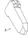
图7A表示了第一、第二和第三优选实施例的上述小面干涉螺钉中的一个的后方透视图,其包括优选的防旋转机构;Figure 7A shows a rear perspective view of one of the aforementioned facet interference screws of the first, second and third preferred embodiments, including the preferred anti-rotation mechanism;
图7B表示了第一、第二和第三优选实施例的上述小面干涉螺钉中的一个的后方透视图,其包括可选的优选防旋转机构;Figure 7B shows a rear perspective view of one of the aforementioned facet interference screws of the first, second and third preferred embodiments, including the optional preferred anti-rotation mechanism;
图8表示了根据本发明的优选方法,根据第一、第二和第三优选实施例中的至少一个的两个小面干涉螺钉的后方透视图,所述两个小面干涉螺钉同时插入病人脊骨的小面关节中;Figure 8 shows a rear perspective view of two facet interference screws simultaneously inserted into a patient according to at least one of the first, second and third preferred embodiments according to a preferred method of the present invention In the facet joints of the spine;
图9A表示了图4A的小面干涉螺钉安装在优选的螺丝刀上的顶部透视图,其中,螺丝刀的优选套筒(以虚线表示)处于延伸位置;Figure 9A shows a top perspective view of the facet interference screw of Figure 4A installed on a preferred screwdriver with the preferred socket (shown in phantom) of the screwdriver in an extended position;
图9B表示了在图9A的圆9B中的图4A的小面干涉螺钉顶部透视图;Figure 9B shows a top perspective view of the facet interference screw of Figure 4A in
图9C表示了安装在螺丝刀上的、图4A的小面干涉螺钉的侧向透视图,该螺丝刀的套筒处于缩回位置;以及9C shows a side perspective view of the facet interference screw of FIG. 4A installed on a screwdriver with the socket in a retracted position; and
图9D表示了安装在螺丝刀上的、图4A的小面干涉螺钉的放大顶部透视图,该螺丝刀的套筒处于进一步缩回位置。9D shows an enlarged top perspective view of the facet interference screw of FIG. 4A installed on a screwdriver with the socket of the screwdriver in a further retracted position.
具体实施方式 Detailed ways
下面的说明书中使用的某些术语只是为了方便,而不是限定。词语“右”、“左”、“顶部”和“底部”表示所参考的图中的方向。词语“内侧”和“外侧”是指分别朝向和远离小面干涉螺钉和其所表示部件的几何中心的方向。词语“前面”、“后面”、“上面”、“下面”、“侧面”、“径向”、“轴向”、“冠状”和相关词语和/或短语是指所参考的人体的优选位置和方位,而不是进行限制。术语包括上述词语、衍生词和类似意思的词。Certain terms used in the following description are for convenience only and not for limitation. The words "right", "left", "top" and "bottom" indicate directions in the drawings to which reference is made. The words "medial" and "lateral" refer to directions toward and away from, respectively, the geometric center of the facet interference screw and the component it represents. The words "anterior", "posterior", "superior", "inferior", "lateral", "radial", "axial", "coronal" and related words and/or phrases refer to the preferred position of the human body with reference to and orientation, rather than constraints. Terminology includes the above words, derivatives and words of similar import.
下面将参考附图介绍本发明的某些示例实施例。本发明的优选实施例涉及:(i)小面干涉螺钉10、10′、10″的第一、第二和第三优选实施例,用于插入在相邻上侧和下侧椎骨V的小面关节FJ之间;以及(ii)用于在病人的脊骨的相邻上侧和下侧椎骨V的小面关节FJ之间插入优选的小面干涉螺钉10、10′、10″的示例外科手术方法。应当知道,尽管本申请的优选小面干涉螺钉10、10′、10″介绍为和大致可以用于脊骨(例如腰部、胸部或颈部区域),但是本领域技术人员应当知道,优选的小面干涉螺钉10、10′、10″以及它的部件可以用于身体其它部分,例如膝盖、臀部、肩部、手指、关节、手、脸、脚中的长骨或骨,例如包括手的掌骨、小多角骨(trapecoidal)和腕舟骨关节以及脚的跖骨-趾骨关节等。Some exemplary embodiments of the present invention will be described below with reference to the accompanying drawings. Preferred embodiments of the present invention relate to: (i) first, second and third preferred embodiments of facet interference screws 10, 10', 10", for insertion in the small facets of adjacent superior and inferior vertebrae V; between the facet joints FJ; and (ii) for inserting the preferred facet interference screws 10, 10', 10" between the facet joints FJ of the adjacent superior and inferior vertebra V of the patient's spine Surgical method. It should be appreciated that although the preferred facet interference screws 10, 10', 10" of the present application are described and generally applicable to the spine (e.g., lumbar, thoracic or cervical regions), those skilled in the art will appreciate that the preferred small The
参考图1A和1B,图中表示了在病人脊骨的腰部区域中的两个示例椎骨V。各椎骨V包括在棘突SP各侧的一对上侧关节小面Fs和一对下侧关节小面Fi。在上侧椎骨V上的下侧小面Fi和在下侧椎骨V上的上侧小面Fs通过关节囊或小面关节空间FJ1、FJ2而可运动地相互连接,该关节囊或小面关节空间FJ1、FJ2引导和限制运动段的运动。图1A和1B中所示的椎骨V包括位于棘突SP左侧的第一小面关节FJ1和位于棘突SP右侧的第二小面关节FJ2。第一和第二小面关节FJ1、FJ2分别包括第一和第二小面关节平面FJp1、FJp2,它们大致定向在大部分腰部脊骨中的矢状平面Sp内。Referring to Figures 1A and 1B, there are shown two example vertebrae V in the lumbar region of a patient's spine. Each vertebra V includes a pair of superior facets Fs and a pair of inferior facets Fi on each side of the spinous process SP. The lower facet Fi on the upper vertebra V and the upper facet Fs on the lower vertebra V are movably connected to each other via joint capsules or facet joint spaces FJ 1 , FJ 2 which The joint spaces FJ 1 , FJ 2 guide and constrain the motion of the motion segments. The vertebra V shown in Figures 1A and 1B includes a first facet joint FJ1 on the left side of the spinous process SP and a second facet joint FJ2 on the right side of the spinous process SP. The first and second facet joints FJ 1 , FJ 2 include first and second facet joint planes FJ pi , FJ p2 , respectively, which are generally oriented in the sagittal plane Sp in most of the lumbar spine.
小面关节FJ1、FJ2引导和便于在上侧和下侧椎骨V之间的运动。由于脊骨S的自然或损伤退化,小面关节FJ1、FJ2可能受到影响。例如,当小面关节FJ1、FJ2的软骨表面退化时,可能产生炎症反应,这可能导致在形成于上侧椎骨V上的下侧小面Fi和形成于下侧椎骨V上的上侧小面Fs之间直接接触,从而引起小面关节FJ1、FJ2疼痛。Facet joints FJ 1 , FJ 2 guide and facilitate motion between the superior and inferior vertebra V. Facet joints FJ 1 , FJ 2 may be affected due to natural or lesion degeneration of spine S. For example, when the cartilaginous surfaces of the facet joints FJ 1 , FJ 2 degenerate, an inflammatory response may occur, which may result in the inferior facet Fi formed on the upper vertebra V and the upper facet Fi formed on the lower vertebra V. The direct contact between the facets Fs causes pain in the facet joints FJ 1 , FJ 2 .
增大小面关节FJ1、FJ2以便减轻在疼痛区域上的压力可以通过在形成于上侧椎骨V上的下侧小面Fi和形成于下侧椎骨V上的上侧小面Fs之间插入植入件(优选地小面干涉螺钉10、10′、10″)来实现。优选的小面干涉螺钉10、10′、10″能够处理小面关节FJ1、FJ2,从而能够保留活动性和/或稳定性,同时能够在任何时候需要额外的内部固定时使得椎弓根(pedicle)保持完整。增大小面关节FJ1、FJ2可以通过插入两个优选的小面干涉螺钉10、10′、10″来实现,一个小面干涉螺钉10、10′、10″用于一个小面关节FJ1、FJ2。此外,优选的小面干涉螺钉10、10′、10″可以在有或没有间隔件的情况下插入在相邻椎骨V之间的椎间盘空间Ds中。Enlarging the facet joints FJ 1 , FJ 2 to relieve pressure on the painful area can be achieved by inserting between the inferior facet Fi formed on the upper vertebra V and the upper facet Fs formed on the lower vertebra V implants (preferably facet interference screws 10, 10', 10"). The preferred facet interference screws 10, 10', 10" are able to address the facet joints FJ 1 , FJ 2 so that mobility can be preserved and/or stability, while being able to keep the pedicle intact whenever additional internal fixation is required. Enlarging the facet joints FJ 1 , FJ 2 can be achieved by inserting two preferred facet interference screws 10 , 10 ′, 10 ″, one
参考图2A和2B,小面干涉螺钉10的第一优选实施例大致成骨螺钉10的形式。第一优选实施例的小面干涉螺钉10包括头部部分14和外螺纹杆部分16。头部部分14优选地包括用于与螺丝刀225接合的机构。例如,头部部分14优选地包括多个凹口44,用于与形成于螺丝刀225的尖端228上的多个凸起229接合(如后面更详细所述),尽管可以考虑其它结构,包括但不局限于:内部凹口、外部六边形、星形驱动模式、十字槽螺丝帽模式、用于螺丝刀的狭槽、用于相应螺杆的螺纹等。杆16的特殊特征(包括例如螺纹节距、自钻孔结构、自攻结构、杆直径、杆形状等)可以互换,且本领域技术人员显然知道,小面干涉螺钉10并不局限于任何特殊类型的杆16或螺纹结构。Referring to FIGS. 2A and 2B , a first preferred embodiment of a
第一优选实施例的小面干涉螺钉或骨螺钉10沿小面干涉螺钉10的纵向轴线13纵向分开,这样,小面干涉螺钉10包括第一部件20和第二部件30。各第一和第二部件20、30包括外部的优选地半圆形外螺纹表面22、32以及内表面24、34,这样,当连接在一起时,半圆形外螺纹表面22、32形成外螺纹杆部分16。因此,在使用中,小面干涉螺钉10优选地通过例如由螺丝刀225旋转(如下面将更详细地描述)而插入形成于上侧椎骨V上的下侧小面Fi和形成于下侧椎骨V上的上侧小面Fs之间。第一优选实施例的内表面24、34优选地大致连续地从头部部分14延伸至杆部分16的尖端16a,并限定关节式连接平面Rp,第一和第二部件20、30可以在安装位置大致沿该关节式连接平面Rp彼此相对运动,如后面更详细所述。内表面24、34优选地在装配结构和在安装结构中沿它的较大部分进行接触,以便引导第一部件20相对于第二部件30的运动。The facet interference screw or
第一优选实施例的小面干涉螺钉10的第一和第二部件20、30的内表面24、34可以包括弯曲接触表面,该弯曲接触表面有例如凸形和/或凹形表面,用于分别与另外部件20、30的弯曲接触表面相互作用,这样,当插入时,第一部件20可相对于第二部件30沿弯曲或弓形路径运动。也就是,例如第一部件20的内表面24可以包括凸形表面,用于与形成于第二部件30的内表面34上的凹形表面接触。不过,如本领域普通技术人员已知,第二部件30的内表面34可以有凸形表面,而第一部件20的内表面24可以有凹形表面。也可选择,两个内表面24、34可以有凹形表面或凸形表面。内表面24、34的凸形或凹形形状(导致在第一和第二部件之间的弓形运动路径)优选地在安装位置安装在一个小面关节FJ1、FJ2中,以便大致模拟小面关节FJ1、FJ2的配合表面的自然弓形形状,如本领域普通技术人员已知的那样。The
第一和第二部件20、30的内表面24、34还可以包括插管开口42,用于接收引导线200(图8),如后面更详细所述。The
参考图2C,第一优选实施例的小面干涉螺钉10还可以包括临时间隔件40,该临时间隔件40至少在插入结构中位于第一和第二部件20、30的内表面24、34之间。优选地,临时间隔件40包括用于接收引导线200(图8)的插管开口42,如后面更详细所述。在使用时,临时间隔件40在插入结构中插入在第一和第二部件20、30的内表面24、34之间。具有安装于其中的临时间隔件40的小面干涉螺钉10通过小面干涉螺钉10的旋转而插入形成于上侧椎骨V上的下侧小面Fi和形成于下侧椎骨V上的上侧小面Fs之间。一旦位于安装位置,优选地除去间隔件40,内表面24、34相对接合或接触,以便于它们之间的运动。引导线200可以包括在远端处的较大直径部分202,该较大直径部分202与临时间隔件40接合并在从小面关节FJ1、FJ2上除去引导线200时除去该临时间隔件40。这样,间隔件40有利于第一优选实施例的小面干涉螺钉10借助于引导线200而插入在下侧小面Fi和上侧小面Fs之间。在使用时,间隔件40防止在第一和第二部件20、30的内表面24、34之间进行表面接触。在安装位置,优选地,间隔件40的取出使得弯曲内表面24、34能够沿弯曲或弓形路径而连接。此外,第一优选实施例的小面干涉螺钉10位于安装位置中,这样,小面干涉螺钉10的关节式连接平面Rp分别大致平行于第一或第二小面关节平面FJp1、FJp2,以便于各小面关节FJ1、FJ2恢复接近正常的关节式连接或运动。Referring to FIG. 2C , the
参考图3A-3D,小面干涉螺钉10′的第二优选实施例与小面干涉螺钉10的第一优选实施例类似,除了小面干涉螺钉10′的第二优选实施例包括位于第一和第二部件20′、30′的内表面(在第二优选实施例中未示出)之间的阻尼部件60a′、60b′、60c′,以便于阻尼和/或第一和第二部件20′、30′的彼此相对运动。第二优选实施例的小面干涉螺钉10′用类似参考标号表示类似元件,并加上符号(′),以便于区别第二优选实施例的小面干涉螺钉10′的元件。优选的阻尼部件60a′、60b′、60c′优选地便于第一和第二部件20′、30′相对于彼此压缩。此外,优选的阻尼部件60a′、60b′、60c′能够在第一和第二部件20′、30′之间进行横向和纵向运动。阻尼部件60a′、60b′、60c′优选地由相对弹性的材料来构成,其使得在第一和第二部件20′、30′之间能够沿六个自由度运动。例如,阻尼部件60a′、60b′、60c′可以由聚合物材料构成,该聚合物材料足够强,以便承受小面干涉螺钉10′在安装于小面关节FJ中时遇到的典型负载,并能够承受在永久性植入小面关节FJ内时遇到的环境。3A-3D, the second preferred embodiment of the facet interference screw 10' is similar to the first preferred embodiment of the
第二优选实施例的阻尼部件60a′、60b′、60c′可以通过本领域目前或以后已知的任意机构而与第一和/或第二部件20′、30′预先装配和/或连接,该机构包括但不局限于:粘接剂、机械连接件等。也可选择,阻尼部件60a′、60b′、60c′可以在第一和第二部件20′、30′在安装位置插入小面关节FJ内之后插入内表面24′、34′之间,其中有或没有临时间隔件(图3A-3D中未示出)。也就是,例如第二优选实施例的小面干涉螺钉10′可以插入小面关节FJ中,然后,第一和第二部件20′、30′可以分开,以便在它们之间接收阻尼部件60a′、60b′、60c′。The damping members 60a', 60b', 60c' of the second preferred embodiment may be pre-assembled and/or connected to the first and/or second members 20', 30' by any mechanism now or hereafter known in the art, The mechanism includes, but is not limited to: adhesives, mechanical connectors, and the like. Alternatively, the damping members 60a', 60b', 60c' may be inserted between the inner surfaces 24', 34' after the first and second members 20', 30' are inserted into the facet joint FJ in the installed position, wherein Or without a temporary spacer (not shown in Figures 3A-3D). That is, for example, the facet interference screw 10' of the second preferred embodiment can be inserted into the facet joint FJ, and then the first and second parts 20', 30' can be separated to receive the damping part 60a' therebetween. , 60b', 60c'.
在第二优选实施例中,阻尼部件60a′、60b′、60c′可以有多种结构,包括:第一优选阻尼部件60a′,它包括在其中的插管开口42′;第二优选阻尼部件60b′,它是大致实心和连续的;以及第三优选阻尼部件60c′,它包括引导和锁定机构70′。第一优选阻尼部件60a′包括插管开口42′,以便在小面干涉螺钉10′的植入过程中使得引导线200容纳于其中。优选地,第一优选阻尼部件60a′在植入小面关节FJ内之前永久性地粘接在第一和第二部件20′、30′上。第二优选阻尼部件60b′包括大致实心的整体结构,而没有插管开口42′。第二优选阻尼部件60b′可以永久性地粘接或连接在第一和第二部件20′、30′上,或者可以在最初植入和除去间隔件40′(图3A-3D中未示出)之后插入在第一和第二部件20′、30′之间。第三优选阻尼部件60c′优选地包括引导和锁定机构70′,以便于阻尼部件60c′插入在第一和第二部件20′、30′之间。引导和锁定机构70′可以包括目前或以后已知的任意机构,包括但不局限于:舌片和槽系统。例如,第一和第二部件20′、30′中的至少一个的内表面24′、34′可以包括槽(未示出),用于与从阻尼部件60′伸出的T形锁定机构70′匹配。此外,与第一和第二部件20′、30′匹配的第一和第二优选阻尼部件60a′、60b′的表面并不局限于大致扁平和连续,如图所示,而是可以包括接合特征,或者可以大致粗糙,以便于与第一和第二部件20′、30′的内表面进行接合和匹配。例如,第一、第二和/或第三阻尼部件60a′、60b′、60c′可以注塑模制在第一和第二部件20′、30′上,该第一和第二部件20′、30′具有粗糙、开槽、有尖顶或其它不平坦内表面,从而有助于将阻尼部件60a′、60b′、60c′保持在第一和第二部件20′、30′上。In the second preferred embodiment, the damping members 60a', 60b', 60c' can have a variety of configurations, including: a first preferred damping member 60a' including the cannula opening 42' therein; a second preferred damping
参考图4A-6B,小面干涉螺钉10″的第三优选实施例包括两件式阻尼部件60″,尽管也考虑了三个或更多件。第三优选实施例的小面干涉螺钉10″用类似参考标号表示类似元件,并加上符号(″),以便于区别第三优选实施例的小面干涉螺钉10″的元件。两件式阻尼部件60″优选地包括:上部阻尼部件62″,该上部阻尼部件62″安装在第一部件20″的内表面24″上;以及下部阻尼部件64″,该下部阻尼部件64″安装在第二部件30″的内表面34″上。上部和下部阻尼部件62″、64″优选地各自包括弯曲接触表面62a″、64a″,这样,上部阻尼部件62″可相对于下部阻尼部件64″运动,且第一部件20″可相对于第二部件30″运动。更优选地,形成于上部和下部阻尼部件62″、64″上的弯曲接触表面62a″、64a″优选地具有沿纵向方向(例如平行于纵向轴线13″)和沿横向方向(例如垂直于纵向轴线13″)的相应球形表面。这样,球形弯曲接触表面62a″、64a″方便弯曲/伸长的关节式连接和横向关节式连接,如图5A-6B中所示。内表面24″、34″也可以便于用于接收引导线200的插管开口42″来引导第三优选实施例的小面干涉螺钉10″的植入。不过,第三优选实施例的小面干涉螺钉10″并不局限于包括插管开口42″,可以构成为没有插管开口42″,这样,上部和下部阻尼部件62a″、64a″在装配构造中基本沿它们整个球形弯曲接触表面62a″、64a″进行接触。Referring to Figures 4A-6B, a third preferred embodiment of a
优选地,上部和下部阻尼部件62″、64″由聚合物材料构成,该聚合物材料提供一些弹性,但是有足够刚性,以便防止在安装位置处的使用过程中在弯曲接触表面62a″、64a″处明显磨损。例如,上部和下部阻尼部件62″、64″可以由聚醚醚酮(PEEK)材料而构成,但是并不局限于此,且可以由提供阻尼和磨损能力以及能够承受正常工作情况和安装位置的环境的几乎任意材料而构成。此外,第一和第二部件20″、30″优选地由金属材料构成,例如钛或钢,但是并不局限于此,且可以由能够采取第一和第二部件20″、30″的总体形状和承受小面干涉螺钉10″的正常工作情况的几乎任意可生物相容材料而构成。Preferably, the upper and lower damping
参考图7A和7B,第一、第二和第三优选实施例的小面干涉螺钉10、10′、10″还可以包括防旋转机构或特征100a、100b,以便阻止小面干涉螺钉10、10′、10″旋出安装位置。例如,第一防旋转机构100a可以为间隔件100a的形式,该间隔件100a插入在第一和第二部件20、30之间,这样,小面干涉螺钉10、10′、10″的轮廓在安装位置中不再为圆形,因此在安装位置不可能旋出或以其他方式旋转。间隔件100a优选地由阻尼类型材料构成,以便允许在第一和第二部件20、30之间进行限制的运动。更优选地,如图7B中所示,第二优选防旋转间隔件100b可以在它的长度的至少一部分处具有比小面干涉螺钉10、10′、10″的直径宽的宽度,从而进一步限制旋出。防旋转机构100a、100b可以与优选的阻尼部件60a′、60b′、60c′、60″分开和不同,或者可以与它们形成一体。也可选择,小面干涉螺钉10、10′、10″可以包括具有U形的防旋转机构,如美国公开专利申请No.2006/0064099中所述,该美国公开专利申请No.2006/0064099的标题为Articular FacetInterference Screw,申请日为2002年11月13日,该文献被本文参引。Referring to Figures 7A and 7B, the facet interference screws 10, 10', 10" of the first, second and third preferred embodiments may also include an anti-rotation mechanism or
参考图2A、3A、4A、5A、6A和7A,优选实施例的小面干涉螺钉10、10′、10″优选地具有螺钉直径D和螺钉长度L。螺钉长度L优选地在5和25毫米之间,螺钉直径D优选地在4和11毫米之间。小面干涉螺钉10、10′、10″并不局限于这些尺寸,但优选地落在这些范围内,以便允许将小面干涉螺钉10、10′、10″微创插入小面关节FJ中、限制尖端16a穿过小面关节FJ延伸、使得小面干涉螺钉10、10′、10″能够在微创手术过程中穿过插管(未示出)运行、以及用于其它相关考虑。此外,优选实施例的小面干涉螺钉10、10′、10″优选地包括头部部分14、14′、14″,以便于与插入和/或除去工具接合,并限制小面干涉螺钉10、10′、10″插入小面关节FJ内的距离。Referring to Figures 2A, 3A, 4A, 5A, 6A and 7A, the preferred embodiment facet interference screws 10, 10', 10" preferably have a screw diameter D and a screw length L. The screw length L is preferably between 5 and 25 mm Between, the screw diameter D is preferably between 4 and 11 mm. The
参考图6A-7B,优选实施例的小面干涉螺钉10、10′、10″可以包括在头部14、14″上的关节式连接指示器50、50″,它们与小面干涉螺钉10、10′、10″的关节式连接平面Rp对齐。关节式连接指示器50、50″向外科医生提供了视觉指示器,以便证明小面干涉螺钉10、10′、10″的关节式连接平面Rp与安装位置中的小面关节平面FJp1、FJp2对齐。关节式连接平面Rp的未对准或错误取向通常限制小面干涉螺钉10、10′、10″以它的预定方式操作,并可能导致小面关节FJ熔合。也可选择,外科医生可以选择插入小面干涉螺钉10、10′、10″,使得关节式连接平面Rp与小面关节平面FJp1、FJp2未对准,从而无意中促使在小面关节FJ中熔合。而且,关节式连接指示器50、50″可以弯曲,或者以其它方式提供内表面24、34弯曲的指示,以便产生弯曲的关节式连接路径,这样,外科医生能够通过小面关节FJ的自然弯曲关节连接来布置关节式连接平面Rp。Referring to FIGS. 6A-7B , the preferred embodiment facet interference screws 10, 10', 10" may include
在使用时,优选实施例的小面干涉螺钉10、10′、10″能自攻和/或自钻孔。第一和第二部件20、30优选地单独或者连同优选的临时间隔件40和/或阻尼部件60a′、60b′、60c′、60″通过例如在螺钉头部14中的刚性连接件而预先装配,这样,在使用时,小面干涉螺钉10、10′、10″可以通过用螺丝刀225使得小面干涉螺钉10、10′、10″旋转进入小面关节FJ中而插入,如图8中所示。优选地,小面干涉螺钉10、10′、10″的关节式连接平面Rp与安装位置中的小面关节平面FJp1、FJp2对齐,以便允许小面关节FJ与安装于其中的小面干涉螺钉10、10′、10″关节式连接。也可选择,关节式连接平面Rp可以有意与小面关节平面FJp1、FJp2不对准,以便促进熔合或限制小面关节FJ中的运动。In use, the
参考图9A-9D,用于将小面干涉螺钉10、10′、10″插入、植入和/或驱动到小面关节FJ中的优选螺丝刀225包括用于将第一和第二部件20、30以及任意附加部件固定在一起以及在插入过程中保持足够力矩的机构。优选的螺丝刀225包括杆227和套筒230。杆227优选地包括用于同时与小面干涉螺钉10、10′、10″的第一和第二部件20、30接合的尖端228。该尖端228优选地包括多个凸起229,用于与形成于小面干涉螺钉10、10′、10″的头部部分14中的多个凹口44接合。套筒230优选地从伸出位置(如图9A和9B中的虚线所示)至退回位置(如图9C中所示)可运动地布置在杆227上面,在该伸出位置,套筒230包封与螺丝刀225的远端连接的小面干涉螺钉10、10′、10″,在该退回位置,与螺丝刀225的远端连接的小面干涉螺钉10、10′、10″露出。套筒230优选地通过例如弹簧235而偏压向伸出位置。Referring to FIGS. 9A-9D , a
螺丝刀225优选地在螺丝刀225手柄的近端处包括指示器225a,以便提供小面干涉螺钉10、10′、10″的关节式连接平面Rp的指示。小面干涉螺钉10、10′、10″优选地可沿单个方位安装在螺丝刀225上,这样,指示器225a与小面干涉螺钉10、10′、10″的关节式连接平面Rp对齐。因此,外科医生能够在安装位置验证关节式连接平面Rp的方位,以便与小面关节平面FJp1、FJp2对齐而促进关节式连接,或者未对齐以便促进熔合,如本领域普通技术人员根据本发明的教导可知。The
在使用时,用户优选地使得套筒230运动至退回位置,这样,小面干涉螺钉10、10′、10″可以与螺丝刀225的远端连接。套筒230通过弹簧偏压而运动至伸出位置,这样,小面干涉螺钉10、10′、10″由套筒230包围。在伸出位置,套筒230帮助将小面干涉螺钉10、10′、10″的第一和第二部件20、30保持在一起,这样,小面干涉螺钉10、10′、10″的多个部件可以作为单个单元而旋转到小面关节FJ中。在插入过程中,在套筒230的远端和病人的骨之间的接触使得套筒230从伸出位置运动至退回位置,以便露出小面干涉螺钉10、10′、10″。小面干涉螺钉10、10′、10″被驱动到小面关节FJ中,直到头部14与小面关节FJ的骨接触,且外科医生优选地使得指示器225a与小面关节平面FJp1、FJp2对齐。In use, the user preferably moves the
小面干涉螺钉10、10′、10″在小面关节FJ中的主要固定通过小面干涉螺钉10、10′、10″的杆部分16上的外螺纹与上侧和下侧小面Fs、Fi接合来实现。辅助固定可以通过骨结合来实现。例如,小面干涉螺钉10、10′、10″和(特别是)形成于小面干涉螺钉10、10′、10″的杆部分16上的外螺纹可以为粗糙的和/或进行涂覆,用于骨传导。小面干涉螺钉10、10′、10″可以涂覆有目前或以后已知的任何生物活性涂层,该生物活性涂层包括但不局限于:Ti等离子体喷雾、阳极化表面增强物,例如APC、HA或任何Ca-P增强物等。The main fixation of the
优选的小面干涉螺钉10、10′、10″和防旋转机构100、100′可以由本领域已知的任意生物相容材料来制造,该生物相容材料包括但不局限于:不锈钢、钛、钛合金、聚合物例如PPEK、PEKK、PEK、PEKK-EK,有或没有可选的碳纤维增强物等,超高分子量聚乙烯(UHMWPE)、钴-铬-钼(CCM)等。The preferred
阻尼部件60a′、60b′、60c′、60″可以由本领域已知的任意生物相容材料来制造,该生物相容材料包括但不局限于:弹性体-热塑性聚合物(PCU或聚合硅酮)、多个PUR或硅酮族、共聚物等。优选地,阻尼部件60a′、60b′、60c′、60″的轮廓(例如尺寸和形状)与第一和第二部件20、30的轮廓(例如尺寸和形状)匹配或基本匹配。阻尼部件60a′、60b′、60c′、60″可以局部或完全进行涂覆,以便降低磨损量。例如,阻尼部件60a′、60b′、60c′、60″可以涂覆有任何金属碳化物或氮化物、DLC族的元素、Al2O3、ZrO2、TiC、TiN、(A)DLC、CrN、CrC等。Damping members 60a', 60b', 60c', 60" may be fabricated from any biocompatible material known in the art including, but not limited to, elastomer-thermoplastic polymers (PCU or polymeric silicone ), multiple PUR or silicone families, copolymers, etc. Preferably, the profile (eg, size and shape) of the damping components 60a', 60b', 60c', 60" is consistent with the profiles of the first and
外科手术技术surgical technique
第一、第二和第三优选实施例的小面干涉螺钉10、10′、10″可以通过本领域已知的任何外科手术技术来插入。小面干涉螺钉10、10′、10″可以经皮插入,类似于在美国专利申请No.11/126976中所述的小面干涉螺钉的插入,该美国专利申请No.11/126976的标题为ArticularFacet Interference Screw,它的申请日为2005年5月10日,并转让给Synthes(U.S.A),该文献整个被本文参引。The facet interference screws 10, 10', 10" of the first, second and third preferred embodiments may be inserted by any surgical technique known in the art. The facet interference screws 10, 10', 10" may be inserted via Skin insertion, similar to the insertion of a facet interference screw as described in U.S. Patent Application No. 11/126976, entitled Articular Facet Interference Screw, filed May 2005 10, and assigned to Synthes (U.S.A), which is incorporated herein by reference in its entirety.
参考图8,在使用时,第一、第二和第三优选实施例的小面干涉螺钉10、10′、10″通过微创手术过程而插入小面关节FJ中。可以设想,小面干涉螺钉10、10′、10″也可以通过开放外科手术来插入。在插入小面干涉螺钉10、10′、10″的一个示例方法中,引导线200被经皮引入在相邻上侧和下侧椎骨V之间的各小面关节FJ中。引导线200的引入可以通过任意方式(包括但不局限于:C形臂造影、CT扫描、微型开口接近小面关节FJ等)而引导到小面关节FJ中。在验证引导线200的对称位置之后,可选的组织保护套筒、插管、牵引器和/或套管针(未示出)可以引导到小面关节FJ,以便打开通向小面关节FJ的通路。小面干涉螺钉10、10′、10″引入小面关节FJ中,优选地通过引导线200和通过保护套筒、插管、牵引器或套管针。然后,小面干涉螺钉10、10′、10″的方位优选地进行校验,并除去引导线200、仪器和临时间隔件40(当需要时)。需要时,阻尼部件60a′、60b′、60c′、60″和防旋转机构100a、100b(如果需要)可以插入第一和第二部件20、30的内表面24、34之间。关节式连接平面Rp的方位由一个或两个指示器50、225a来验证,特别是相对于小面关节平面FJp1、FJp2来验证。Referring to Figure 8, in use, the facet interference screws 10, 10', 10" of the first, second and third preferred embodiments are inserted into the facet joint FJ by a minimally invasive surgical procedure. It is contemplated that the facet interference The
本领域技术人员应当知道,在不脱离本发明的广义概念的情况下可以对上述实施例进行改变。因此,应当知道,本发明并不局限于所述特殊实施例,而是将覆盖在如附加权利要求确定的本发明精神和范围内的变化。It will be appreciated by those skilled in the art that changes may be made to the above-described embodiments without departing from the broad concepts of the invention. It is understood, therefore, that this invention is not limited to the particular embodiments described, but it is intended to cover variations within the spirit and scope of the present invention as defined by the appended claims.
Claims (7)
Applications Claiming Priority (3)
| Application Number | Priority Date | Filing Date | Title |
|---|---|---|---|
| US3429508P | 2008-03-06 | 2008-03-06 | |
| US61/034,295 | 2008-03-06 | ||
| PCT/US2009/036175 WO2009111632A1 (en) | 2008-03-06 | 2009-03-05 | Facet interference screw |
Publications (2)
| Publication Number | Publication Date |
|---|---|
| CN101959468A CN101959468A (en) | 2011-01-26 |
| CN101959468B true CN101959468B (en) | 2012-09-05 |
Family
ID=40848087
Family Applications (1)
| Application Number | Title | Priority Date | Filing Date |
|---|---|---|---|
| CN200980106809XA Expired - Fee Related CN101959468B (en) | 2008-03-06 | 2009-03-05 | Facet interference screw |
Country Status (9)
| Country | Link |
|---|---|
| US (1) | US8696708B2 (en) |
| EP (1) | EP2249730A1 (en) |
| JP (1) | JP2011514208A (en) |
| KR (1) | KR20100137435A (en) |
| CN (1) | CN101959468B (en) |
| BR (1) | BRPI0908122A2 (en) |
| CA (1) | CA2717610A1 (en) |
| CO (1) | CO6300917A2 (en) |
| WO (1) | WO2009111632A1 (en) |
Families Citing this family (58)
| Publication number | Priority date | Publication date | Assignee | Title |
|---|---|---|---|---|
| US20060111779A1 (en) * | 2004-11-22 | 2006-05-25 | Orthopedic Development Corporation, A Florida Corporation | Minimally invasive facet joint fusion |
| US8008497B2 (en) * | 2006-11-14 | 2011-08-30 | Santen Pharmaceutical Co., Ltd. | 1,2-dihydroquinoline derivative having (substituted phenyl or substituted heterocyclic) carbonyloxy lower alkyl group and ester-introduced phenyl group as substituents |
| US20080161929A1 (en) | 2006-12-29 | 2008-07-03 | Mccormack Bruce | Cervical distraction device |
| US9005288B2 (en) | 2008-01-09 | 2015-04-14 | Providence Medical Techonlogy, Inc. | Methods and apparatus for accessing and treating the facet joint |
| EP2249730A1 (en) | 2008-03-06 | 2010-11-17 | Synthes GmbH | Facet interference screw |
| US9381049B2 (en) * | 2008-06-06 | 2016-07-05 | Providence Medical Technology, Inc. | Composite spinal facet implant with textured surfaces |
| US9333086B2 (en) * | 2008-06-06 | 2016-05-10 | Providence Medical Technology, Inc. | Spinal facet cage implant |
| CA2725811A1 (en) | 2008-06-06 | 2009-12-10 | Providence Medical Technology, Inc. | Facet joint implants and delivery tools |
| US8361152B2 (en) | 2008-06-06 | 2013-01-29 | Providence Medical Technology, Inc. | Facet joint implants and delivery tools |
| US8512347B2 (en) | 2008-06-06 | 2013-08-20 | Providence Medical Technology, Inc. | Cervical distraction/implant delivery device |
| US11224521B2 (en) | 2008-06-06 | 2022-01-18 | Providence Medical Technology, Inc. | Cervical distraction/implant delivery device |
| US8267966B2 (en) | 2008-06-06 | 2012-09-18 | Providence Medical Technology, Inc. | Facet joint implants and delivery tools |
| WO2010011904A2 (en) | 2008-07-25 | 2010-01-28 | Synthes Usa, Llc | Facet joint augmentation with hydrogels |
| US8715321B2 (en) * | 2008-10-01 | 2014-05-06 | Life Spine, Inc. | Spinal facet fastener |
| US8945184B2 (en) * | 2009-03-13 | 2015-02-03 | Spinal Simplicity Llc. | Interspinous process implant and fusion cage spacer |
| JP2011141785A (en) | 2010-01-08 | 2011-07-21 | Girunetto Kk | Member registration system using portable terminal and authentication system |
| JP2011141849A (en) | 2010-01-09 | 2011-07-21 | Girunetto Kk | Prepaid and postpaid payment system using mobile terminal, small-amount transfer method, point service system, and escrow service system |
| US9265622B2 (en) * | 2010-03-22 | 2016-02-23 | Amendia, Inc. | Percutaneous arthrodesis method and system |
| GB201006798D0 (en) | 2010-04-23 | 2010-06-09 | Orthofitz Implants Ltd | Spinal implants and spinal fixings |
| US8986355B2 (en) | 2010-07-09 | 2015-03-24 | DePuy Synthes Products, LLC | Facet fusion implant |
| US8459155B2 (en) * | 2010-09-03 | 2013-06-11 | Smith & Nephew, Inc. | Modified fastener and insertion tool |
| WO2012154653A1 (en) | 2011-05-10 | 2012-11-15 | Synthes Usa, Llc | Facet interference cage |
| EP2723245B1 (en) | 2011-06-23 | 2018-01-03 | Synthes GmbH | Suture anchor system |
| DE102011120046B4 (en) * | 2011-07-20 | 2019-05-29 | Ngmedical Gmbh | Facet joint prosthesis |
| EP2854716A1 (en) * | 2012-05-28 | 2015-04-08 | NLT Spine Ltd. | Surgical impaling member |
| USD732667S1 (en) | 2012-10-23 | 2015-06-23 | Providence Medical Technology, Inc. | Cage spinal implant |
| US10278742B2 (en) | 2012-11-12 | 2019-05-07 | DePuy Synthes Products, Inc. | Interbody interference implant and instrumentation |
| CN103431927A (en) * | 2013-08-09 | 2013-12-11 | 朱悦 | Lumbar zygapophyseal joint fusion device |
| AU2015267055B2 (en) | 2014-05-27 | 2020-04-02 | Christopher U. Phan | Lateral mass fixation implant |
| US10201375B2 (en) | 2014-05-28 | 2019-02-12 | Providence Medical Technology, Inc. | Lateral mass fixation system |
| FR3021864B1 (en) * | 2014-06-06 | 2019-10-25 | In2Bones | SURGICAL IMPLANT, IMPLEMENT TOOL, SURGICAL KIT AND METHOD FOR MANUFACTURING THE SAME |
| US10856966B2 (en) | 2014-10-23 | 2020-12-08 | Medos International Sarl | Biceps tenodesis implants and delivery tools |
| US10076374B2 (en) * | 2014-10-23 | 2018-09-18 | Medos International Sárl | Biceps tenodesis delivery tools |
| US10034742B2 (en) | 2014-10-23 | 2018-07-31 | Medos International Sarl | Biceps tenodesis implants and delivery tools |
| US10751161B2 (en) | 2014-10-23 | 2020-08-25 | Medos International Sárl | Biceps tenodesis anchor implants |
| US10729419B2 (en) * | 2014-10-23 | 2020-08-04 | Medos International Sarl | Biceps tenodesis implants and delivery tools |
| US9693856B2 (en) | 2015-04-22 | 2017-07-04 | DePuy Synthes Products, LLC | Biceps repair device |
| USD841165S1 (en) | 2015-10-13 | 2019-02-19 | Providence Medical Technology, Inc. | Cervical cage |
| WO2017066475A1 (en) | 2015-10-13 | 2017-04-20 | Providence Medical Technology, Inc. | Spinal joint implant delivery device and system |
| FR3048176A1 (en) | 2016-02-26 | 2017-09-01 | Ldr Medical | SPINAL ARTHRODESIS IMPLANT SYSTEM |
| US10231824B2 (en) | 2016-04-08 | 2019-03-19 | Medos International Sárl | Tenodesis anchoring systems and tools |
| US10231823B2 (en) | 2016-04-08 | 2019-03-19 | Medos International Sarl | Tenodesis implants and tools |
| JP2019519334A (en) | 2016-06-28 | 2019-07-11 | プロビデンス メディカル テクノロジー インコーポレイテッド | Spinal implant and method of using spinal implant |
| USD887552S1 (en) | 2016-07-01 | 2020-06-16 | Providence Medical Technology, Inc. | Cervical cage |
| KR101701093B1 (en) | 2016-07-06 | 2017-01-31 | 김주한 | System and method for international payment gateway using mobile terminal |
| KR101680016B1 (en) | 2016-08-04 | 2016-12-06 | 김주한 | Payment ASP System and Methods using a mobile communication terminal |
| JP2020521536A (en) | 2017-05-19 | 2020-07-27 | プロビデンス メディカル テクノロジー インコーポレイテッド | Spinal fixation access and delivery system |
| CN112971886B (en) * | 2017-12-30 | 2022-01-04 | 深圳市立心科学有限公司 | Extrusion nail for fixing ligament and assembling tool thereof |
| US11648128B2 (en) | 2018-01-04 | 2023-05-16 | Providence Medical Technology, Inc. | Facet screw and delivery device |
| WO2020061464A1 (en) | 2018-09-21 | 2020-03-26 | Providence Medical Technology, Inc. | Vertebral joint access and decortication devices and methods of using |
| WO2020163846A1 (en) * | 2019-02-08 | 2020-08-13 | Peter Stevens | Enhanced orthopedic screw |
| USD933230S1 (en) | 2019-04-15 | 2021-10-12 | Providence Medical Technology, Inc. | Cervical cage |
| CN110101446B (en) * | 2019-05-13 | 2021-08-10 | 深圳市立心科学有限公司 | Extrusion nail with self-locking function |
| USD911525S1 (en) | 2019-06-21 | 2021-02-23 | Providence Medical Technology, Inc. | Spinal cage |
| USD945621S1 (en) | 2020-02-27 | 2022-03-08 | Providence Medical Technology, Inc. | Spinal cage |
| EP4633496A1 (en) | 2022-12-13 | 2025-10-22 | Spinal Simplicity, LLC | Medical implant and insertion tool |
| USD1098431S1 (en) | 2023-02-27 | 2025-10-14 | Providence Medical Technology, Inc. | Spinal cage |
| USD1098433S1 (en) | 2023-12-28 | 2025-10-14 | Providence Medical Technology, Inc. | Spinal cage |
Citations (2)
| Publication number | Priority date | Publication date | Assignee | Title |
|---|---|---|---|---|
| US5928284A (en) * | 1998-07-09 | 1999-07-27 | Mehdizadeh; Hamid M. | Disc replacement prosthesis |
| US6419706B1 (en) * | 1997-12-19 | 2002-07-16 | Sofamor S.N.C. | Partial disc prosthesis |
Family Cites Families (196)
| Publication number | Priority date | Publication date | Assignee | Title |
|---|---|---|---|---|
| EP0023787B1 (en) | 1979-07-25 | 1983-07-20 | University Of Exeter | Plugs for the medullary canal of a bone |
| US4501269A (en) | 1981-12-11 | 1985-02-26 | Washington State University Research Foundation, Inc. | Process for fusing bone joints |
| US4754749A (en) | 1986-04-29 | 1988-07-05 | Tsou Paul M | Surgical screw with counter-rotation prevention means |
| JPS6368155A (en) | 1986-09-11 | 1988-03-28 | グンゼ株式会社 | Bone bonding pin |
| US4834757A (en) | 1987-01-22 | 1989-05-30 | Brantigan John W | Prosthetic implant |
| US4940467A (en) | 1988-02-03 | 1990-07-10 | Tronzo Raymond G | Variable length fixation device |
| US5015247A (en) | 1988-06-13 | 1991-05-14 | Michelson Gary K | Threaded spinal implant |
| US5772661A (en) | 1988-06-13 | 1998-06-30 | Michelson; Gary Karlin | Methods and instrumentation for the surgical correction of human thoracic and lumbar spinal disease from the antero-lateral aspect of the spine |
| US6210412B1 (en) | 1988-06-13 | 2001-04-03 | Gary Karlin Michelson | Method for inserting frusto-conical interbody spinal fusion implants |
| US5122132A (en) | 1991-08-01 | 1992-06-16 | Bremer Medical, Inc. | Skull pin with enhanced shear resistance |
| DE69317654T2 (en) | 1992-04-28 | 1998-10-01 | Donald R Huene | ABSORBABLE BONE SCREW AND TOOL TO INSERT IT |
| US5334204A (en) | 1992-08-03 | 1994-08-02 | Ace Medical Company | Fixation screw |
| US5709687A (en) | 1994-03-16 | 1998-01-20 | Pennig; Dietmar | Fixation pin for small-bone fragments |
| FR2721501B1 (en) | 1994-06-24 | 1996-08-23 | Fairant Paulette | Prostheses of the vertebral articular facets. |
| US5527312A (en) | 1994-08-19 | 1996-06-18 | Salut, Ltd. | Facet screw anchor |
| CN1134810A (en) | 1995-02-17 | 1996-11-06 | 索发默达纳集团股份有限公司 | Improved interbody spinal fusion implants |
| US5571191A (en) | 1995-03-16 | 1996-11-05 | Fitz; William R. | Artificial facet joint |
| US5782919A (en) * | 1995-03-27 | 1998-07-21 | Sdgi Holdings, Inc. | Interbody fusion device and method for restoration of normal spinal anatomy |
| US6056192A (en) | 1995-05-12 | 2000-05-02 | Cameron; Robert | Rectangular-faced enclosures |
| US6039762A (en) | 1995-06-07 | 2000-03-21 | Sdgi Holdings, Inc. | Reinforced bone graft substitutes |
| US6117162A (en) | 1996-08-05 | 2000-09-12 | Arthrex, Inc. | Corkscrew suture anchor |
| US5895426A (en) | 1996-09-06 | 1999-04-20 | Osteotech, Inc. | Fusion implant device and method of use |
| FR2759282B1 (en) | 1997-02-10 | 1999-05-07 | Eos Medical | BREAKABLE SCREW DEVICE FOR OSTEOSYNTHESIS PLATE OR FOR COAPTATION OF TWO BONE FRAGMENTS |
| US6014588A (en) | 1998-04-07 | 2000-01-11 | Fitz; William R. | Facet joint pain relief method and apparatus |
| US6679915B1 (en) * | 1998-04-23 | 2004-01-20 | Sdgi Holdings, Inc. | Articulating spinal implant |
| US6019792A (en) | 1998-04-23 | 2000-02-01 | Cauthen Research Group, Inc. | Articulating spinal implant |
| AU748746B2 (en) * | 1998-07-22 | 2002-06-13 | Spinal Dynamics Corporation | Threaded cylindrical multidiscoid single or multiple array disc prosthesis |
| US6099529A (en) | 1998-10-26 | 2000-08-08 | Musculoskeletal Transplant Foundation | Allograft bone fixation screw method and apparatus |
| US6162225A (en) | 1998-10-26 | 2000-12-19 | Musculoskeletal Transplant Foundation | Allograft bone fixation screw method and apparatus |
| US6371986B1 (en) | 1998-10-27 | 2002-04-16 | George W. Bagby | Spinal fusion device, bone joining implant, and vertebral fusion implant |
| US6312443B1 (en) | 1998-12-23 | 2001-11-06 | Nuvasive, Inc. | Expandable cannula |
| US6200347B1 (en) | 1999-01-05 | 2001-03-13 | Lifenet | Composite bone graft, method of making and using same |
| US6478805B1 (en) | 1999-04-16 | 2002-11-12 | Nuvasive, Inc. | System for removing cut tissue from the inner bore of a surgical instrument |
| US7094239B1 (en) | 1999-05-05 | 2006-08-22 | Sdgi Holdings, Inc. | Screws of cortical bone and method of manufacture thereof |
| US6494883B1 (en) | 2000-05-26 | 2002-12-17 | Bret A. Ferree | Bone reinforcers |
| ATE285207T1 (en) | 1999-10-22 | 2005-01-15 | Archus Orthopedics Inc | FACET ARTHROPLASTY DEVICES |
| US7691145B2 (en) | 1999-10-22 | 2010-04-06 | Facet Solutions, Inc. | Prostheses, systems and methods for replacement of natural facet joints with artificial facet joint surfaces |
| US6811567B2 (en) | 1999-10-22 | 2004-11-02 | Archus Orthopedics Inc. | Facet arthroplasty devices and methods |
| US20050261770A1 (en) | 2004-04-22 | 2005-11-24 | Kuiper Mark K | Crossbar spinal prosthesis having a modular design and related implantation methods |
| US6974478B2 (en) | 1999-10-22 | 2005-12-13 | Archus Orthopedics, Inc. | Prostheses, systems and methods for replacement of natural facet joints with artificial facet joint surfaces |
| US20050027361A1 (en) | 1999-10-22 | 2005-02-03 | Reiley Mark A. | Facet arthroplasty devices and methods |
| US7674293B2 (en) | 2004-04-22 | 2010-03-09 | Facet Solutions, Inc. | Crossbar spinal prosthesis having a modular design and related implantation methods |
| US8187303B2 (en) | 2004-04-22 | 2012-05-29 | Gmedelaware 2 Llc | Anti-rotation fixation element for spinal prostheses |
| US6485518B1 (en) | 1999-12-10 | 2002-11-26 | Nuvasive | Facet screw and bone allograft intervertebral support and fusion system |
| DE59901090D1 (en) | 1999-12-23 | 2002-05-02 | Storz Karl Gmbh & Co Kg | Decentralized drive screw |
| US7662173B2 (en) | 2000-02-16 | 2010-02-16 | Transl, Inc. | Spinal mobility preservation apparatus |
| US6740093B2 (en) | 2000-02-28 | 2004-05-25 | Stephen Hochschuler | Method and apparatus for treating a vertebral body |
| US6669698B1 (en) | 2000-10-24 | 2003-12-30 | Sdgi Holdings, Inc. | Vertebrae fastener placement guide |
| US6648893B2 (en) | 2000-10-27 | 2003-11-18 | Blackstone Medical, Inc. | Facet fixation devices |
| MXPA03004180A (en) * | 2000-11-13 | 2004-12-02 | Boehm Frank H Jr | Device and method for lumbar interbody fusion. |
| US20050080486A1 (en) | 2000-11-29 | 2005-04-14 | Fallin T. Wade | Facet joint replacement |
| US6579319B2 (en) | 2000-11-29 | 2003-06-17 | Medicinelodge, Inc. | Facet joint replacement |
| US6565605B2 (en) | 2000-12-13 | 2003-05-20 | Medicinelodge, Inc. | Multiple facet joint replacement |
| US6419703B1 (en) | 2001-03-01 | 2002-07-16 | T. Wade Fallin | Prosthesis for the replacement of a posterior element of a vertebra |
| WO2002065954A1 (en) | 2001-02-16 | 2002-08-29 | Queen's University At Kingston | Method and device for treating scoliosis |
| US7090698B2 (en) | 2001-03-02 | 2006-08-15 | Facet Solutions | Method and apparatus for spine joint replacement |
| US7220262B1 (en) | 2001-03-16 | 2007-05-22 | Sdgi Holdings, Inc. | Spinal fixation system and related methods |
| US6547795B2 (en) | 2001-08-13 | 2003-04-15 | Depuy Acromed, Inc. | Surgical guide system for stabilization of the spine |
| FR2832054B1 (en) | 2001-11-15 | 2004-09-10 | Rene Louis | POSTERIOR VERTEBRAL JOINT PROSTHESIS |
| US6685706B2 (en) | 2001-11-19 | 2004-02-03 | Triage Medical, Inc. | Proximal anchors for bone fixation system |
| AU2002362220A1 (en) | 2001-12-27 | 2003-07-24 | Osteotech Inc. | Bone fasteners and method for stabilizing vertebral bone facets using the bone fasteners |
| US6669729B2 (en) | 2002-03-08 | 2003-12-30 | Kingsley Richard Chin | Apparatus and method for the replacement of posterior vertebral elements |
| US7179294B2 (en) * | 2002-04-25 | 2007-02-20 | Warsaw Orthopedic, Inc. | Articular disc prosthesis and method for implanting the same |
| US20030208202A1 (en) | 2002-05-04 | 2003-11-06 | Falahee Mark H. | Percutaneous screw fixation system |
| DE10233085B4 (en) * | 2002-07-19 | 2014-02-20 | Dendron Gmbh | Stent with guide wire |
| DE60330010D1 (en) * | 2002-07-19 | 2009-12-24 | Interventional Spine Inc | DEVICE FOR SPINAL FUSING |
| US20040087948A1 (en) | 2002-08-29 | 2004-05-06 | Loubert Suddaby | Spinal facet fixation device |
| US7608094B2 (en) | 2002-10-10 | 2009-10-27 | U.S. Spinal Technologies, Llc | Percutaneous facet fixation system |
| US20080221692A1 (en) * | 2002-10-29 | 2008-09-11 | Zucherman James F | Interspinous process implants and methods of use |
| WO2004043278A1 (en) | 2002-11-13 | 2004-05-27 | Synthes Ag Chur | Articular facet interference screw |
| US7223269B2 (en) | 2002-12-02 | 2007-05-29 | Chappuis James L | Facet fusion system |
| US20050124993A1 (en) | 2002-12-02 | 2005-06-09 | Chappuis James L. | Facet fusion system |
| US7101398B2 (en) | 2002-12-31 | 2006-09-05 | Depuy Acromed, Inc. | Prosthetic facet joint ligament |
| US20050055096A1 (en) | 2002-12-31 | 2005-03-10 | Depuy Spine, Inc. | Functional spinal unit prosthetic |
| US7282064B2 (en) | 2003-02-11 | 2007-10-16 | Spinefrontier Lls | Apparatus and method for connecting spinal vertebrae |
| US7588589B2 (en) | 2003-03-20 | 2009-09-15 | Medical Designs Llc | Posterior spinal reconstruction system |
| US7608104B2 (en) | 2003-05-14 | 2009-10-27 | Archus Orthopedics, Inc. | Prostheses, tools and methods for replacement of natural facet joints with artifical facet joint surfaces |
| US20040230304A1 (en) | 2003-05-14 | 2004-11-18 | Archus Orthopedics Inc. | Prostheses, tools and methods for replacement of natural facet joints with artifical facet joint surfaces |
| US20040230201A1 (en) | 2003-05-14 | 2004-11-18 | Archus Orthopedics Inc. | Prostheses, tools and methods for replacement of natural facet joints with artifical facet joint surfaces |
| US7749251B2 (en) | 2003-06-13 | 2010-07-06 | Aeolin, Llc | Method and apparatus for stabilization of facet joint |
| US7074238B2 (en) | 2003-07-08 | 2006-07-11 | Archus Orthopedics, Inc. | Prostheses, tools and methods for replacement of natural facet joints with artificial facet joint surfaces |
| US20050015150A1 (en) | 2003-07-17 | 2005-01-20 | Lee Casey K. | Intervertebral disk and nucleus prosthesis |
| US7537611B2 (en) | 2003-07-17 | 2009-05-26 | Lee Casey K | Facet joint prosthesis |
| US7708766B2 (en) | 2003-08-11 | 2010-05-04 | Depuy Spine, Inc. | Distraction screw |
| US9254137B2 (en) | 2003-08-29 | 2016-02-09 | Lanterna Medical Technologies Ltd | Facet implant |
| AU2003285751A1 (en) | 2003-10-20 | 2005-05-05 | Impliant Ltd. | Facet prosthesis |
| US20050101953A1 (en) | 2003-11-10 | 2005-05-12 | Simonson Peter M. | Artificial facet joint and method |
| US7083622B2 (en) | 2003-11-10 | 2006-08-01 | Simonson Peter M | Artificial facet joint and method |
| US7708764B2 (en) | 2003-11-10 | 2010-05-04 | Simonson Peter M | Method for creating an artificial facet |
| US8926700B2 (en) | 2003-12-10 | 2015-01-06 | Gmedelware 2 LLC | Spinal facet joint implant |
| US7553320B2 (en) | 2003-12-10 | 2009-06-30 | Warsaw Orthopedic, Inc. | Method and apparatus for replacing the function of facet joints |
| US20050131406A1 (en) | 2003-12-15 | 2005-06-16 | Archus Orthopedics, Inc. | Polyaxial adjustment of facet joint prostheses |
| US20050149030A1 (en) | 2003-12-19 | 2005-07-07 | Depuy Spine, Inc. | Facet joint fixation system |
| US20050159746A1 (en) | 2004-01-21 | 2005-07-21 | Dieter Grob | Cervical facet resurfacing implant |
| US7846183B2 (en) | 2004-02-06 | 2010-12-07 | Spinal Elements, Inc. | Vertebral facet joint prosthesis and method of fixation |
| US7993373B2 (en) | 2005-02-22 | 2011-08-09 | Hoy Robert W | Polyaxial orthopedic fastening apparatus |
| US8562649B2 (en) | 2004-02-17 | 2013-10-22 | Gmedelaware 2 Llc | System and method for multiple level facet joint arthroplasty and fusion |
| US8353933B2 (en) | 2007-04-17 | 2013-01-15 | Gmedelaware 2 Llc | Facet joint replacement |
| US20050197700A1 (en) | 2004-02-18 | 2005-09-08 | Boehm Frank H.Jr. | Facet joint prosthesis and method of replacing a facet joint |
| US20050209694A1 (en) | 2004-03-12 | 2005-09-22 | Loeb Marvin P | Artificial spinal joints and method of use |
| US7914556B2 (en) | 2005-03-02 | 2011-03-29 | Gmedelaware 2 Llc | Arthroplasty revision system and method |
| US7051451B2 (en) | 2004-04-22 | 2006-05-30 | Archus Orthopedics, Inc. | Facet joint prosthesis measurement and implant tools |
| US7406775B2 (en) | 2004-04-22 | 2008-08-05 | Archus Orthopedics, Inc. | Implantable orthopedic device component selection instrument and methods |
| US20070093833A1 (en) | 2004-05-03 | 2007-04-26 | Kuiper Mark K | Crossbar spinal prosthesis having a modular design and related implantation methods |
| CA2567833A1 (en) | 2004-05-27 | 2005-12-15 | Depuy Spine, Inc. | Tri-joint implant |
| US20050277921A1 (en) | 2004-05-28 | 2005-12-15 | Sdgi Holdings, Inc. | Prosthetic joint and nucleus supplement |
| US7588578B2 (en) | 2004-06-02 | 2009-09-15 | Facet Solutions, Inc | Surgical measurement systems and methods |
| US8764801B2 (en) | 2005-03-28 | 2014-07-01 | Gmedelaware 2 Llc | Facet joint implant crosslinking apparatus and method |
| US7935136B2 (en) | 2004-06-17 | 2011-05-03 | Alamin Todd F | Facet joint fusion devices and methods |
| US20060036323A1 (en) | 2004-08-03 | 2006-02-16 | Carl Alan L | Facet device and method |
| US8114158B2 (en) | 2004-08-03 | 2012-02-14 | Kspine, Inc. | Facet device and method |
| US7846184B2 (en) | 2004-08-13 | 2010-12-07 | Sasso Ricardo C | Replacement facet joint and method |
| US8491634B2 (en) | 2004-08-13 | 2013-07-23 | Ricardo C. Sasso | Replacement facet joint and method |
| US20060041311A1 (en) | 2004-08-18 | 2006-02-23 | Mcleer Thomas J | Devices and methods for treating facet joints |
| JP2008510518A (en) | 2004-08-18 | 2008-04-10 | アーカス・オーソペディクス・インコーポレーテッド | Adjoint level articulating device, spinal stabilization system and method |
| US7896906B2 (en) | 2004-12-30 | 2011-03-01 | Depuy Spine, Inc. | Artificial facet joint |
| US20060084976A1 (en) | 2004-09-30 | 2006-04-20 | Depuy Spine, Inc. | Posterior stabilization systems and methods |
| US8092496B2 (en) | 2004-09-30 | 2012-01-10 | Depuy Spine, Inc. | Methods and devices for posterior stabilization |
| US7766940B2 (en) | 2004-12-30 | 2010-08-03 | Depuy Spine, Inc. | Posterior stabilization system |
| US20060085075A1 (en) | 2004-10-04 | 2006-04-20 | Archus Orthopedics, Inc. | Polymeric joint complex and methods of use |
| US7452369B2 (en) | 2004-10-18 | 2008-11-18 | Barry Richard J | Spine microsurgery techniques, training aids and implants |
| US8721722B2 (en) * | 2004-10-18 | 2014-05-13 | Ebi, Llc | Intervertebral implant and associated method |
| CA2585135A1 (en) | 2004-10-25 | 2006-05-26 | Archus Orthopedics, Inc. | Spinal prosthesis having a modular design |
| US20070016297A1 (en) | 2004-11-18 | 2007-01-18 | University Of South Florida | Prostheses for Spine Facets |
| US20060111780A1 (en) | 2004-11-22 | 2006-05-25 | Orthopedic Development Corporation | Minimally invasive facet joint hemi-arthroplasty |
| US7837713B2 (en) | 2004-11-22 | 2010-11-23 | Minsurg International, Inc. | Methods and surgical kits for minimally-invasive facet joint fusion |
| US8021392B2 (en) | 2004-11-22 | 2011-09-20 | Minsurg International, Inc. | Methods and surgical kits for minimally-invasive facet joint fusion |
| US20060111779A1 (en) | 2004-11-22 | 2006-05-25 | Orthopedic Development Corporation, A Florida Corporation | Minimally invasive facet joint fusion |
| US8128660B2 (en) | 2004-12-13 | 2012-03-06 | Kyphon Sarl | Inter-cervical facet joint implant with locking screw system |
| US20060247633A1 (en) | 2004-12-13 | 2006-11-02 | St. Francis Medical Technologies, Inc. | Inter-cervical facet implant with surface enhancements |
| US20070016196A1 (en) | 2005-05-10 | 2007-01-18 | Winslow Charles J | Inter-cervical facet implant with implantation tool |
| US8029540B2 (en) | 2005-05-10 | 2011-10-04 | Kyphon Sarl | Inter-cervical facet implant with implantation tool |
| US7591851B2 (en) | 2004-12-13 | 2009-09-22 | Kyphon Sarl | Inter-cervical facet implant and method |
| US8100944B2 (en) | 2004-12-13 | 2012-01-24 | Kyphon Sarl | Inter-cervical facet implant and method for preserving the tissues surrounding the facet joint |
| US7655044B2 (en) | 2004-12-13 | 2010-02-02 | Depuy Spine, Inc. | Artificial facet joint device having a compression spring |
| US8118838B2 (en) | 2004-12-13 | 2012-02-21 | Kyphon Sarl | Inter-cervical facet implant with multiple direction articulation joint and method for implanting |
| US20060190081A1 (en) | 2005-02-09 | 2006-08-24 | Gary Kraus | Facet stabilization schemes |
| US8696707B2 (en) | 2005-03-08 | 2014-04-15 | Zyga Technology, Inc. | Facet joint stabilization |
| US8496686B2 (en) | 2005-03-22 | 2013-07-30 | Gmedelaware 2 Llc | Minimally invasive spine restoration systems, devices, methods and kits |
| US20070088358A1 (en) | 2005-03-22 | 2007-04-19 | Hansen Yuan | Minimally Invasive Spine Restoration Systems, Devices, Methods and Kits |
| US20060264954A1 (en) | 2005-04-07 | 2006-11-23 | Sweeney Thomas M Ii | Active compression screw system and method for using the same |
| US7828828B2 (en) * | 2005-04-14 | 2010-11-09 | Warsaw Orthopedic, Inc | Intervertebral joint |
| US20060241758A1 (en) | 2005-04-20 | 2006-10-26 | Sdgi Holdings, Inc. | Facet spacers |
| US20060247769A1 (en) | 2005-04-28 | 2006-11-02 | Sdgi Holdings, Inc. | Polycrystalline diamond compact surfaces on facet arthroplasty devices |
| AU2006242412B2 (en) | 2005-05-02 | 2011-12-15 | Seaspine, Inc. | Prosthesis for restoring motion |
| US7799083B2 (en) * | 2005-05-02 | 2010-09-21 | Seaspine, Inc. | Prosthesis for restoring motion in an appendage or spinal joint and an intervertebral spacer |
| US7862589B2 (en) | 2005-05-24 | 2011-01-04 | Lanx, Inc. | Facet replacement |
| US20060276790A1 (en) | 2005-06-02 | 2006-12-07 | Zimmer Spine, Inc. | Minimally invasive facet joint repair |
| US20060282080A1 (en) | 2005-06-08 | 2006-12-14 | Accin Corporation | Vertebral facet stabilizer |
| US7563283B2 (en) | 2005-06-30 | 2009-07-21 | Depuy Spine, Inc. | Non-linear artificial ligament system |
| US20070055257A1 (en) * | 2005-06-30 | 2007-03-08 | Alex Vaccaro | Cannulated screw access system |
| KR101152132B1 (en) * | 2005-08-04 | 2012-06-15 | 삼성전자주식회사 | Liquid crystal display including sensing unit |
| US20070035795A1 (en) | 2005-08-04 | 2007-02-15 | Hubbard Jason R | Artificial facet joint and a method of making same |
| US7799057B2 (en) | 2005-09-02 | 2010-09-21 | Zimmer Spine, Inc. | Translaminar facet augmentation and flexible spinal stabilization |
| US20070055373A1 (en) | 2005-09-08 | 2007-03-08 | Zimmer Spine, Inc. | Facet replacement/spacing and flexible spinal stabilization |
| US20070073290A1 (en) | 2005-09-13 | 2007-03-29 | Boehm Frank H Jr | Insertion of artificial/prosthetic facet joints with ballotable/compressible joint space component |
| US8163024B2 (en) | 2005-09-14 | 2012-04-24 | Premia Spine Ltd. | Adjustable spinal prostheses |
| US20070083200A1 (en) | 2005-09-23 | 2007-04-12 | Gittings Darin C | Spinal stabilization systems and methods |
| US20080287959A1 (en) | 2005-09-26 | 2008-11-20 | Archus Orthopedics, Inc. | Measurement and trialing system and methods for orthopedic device component selection |
| DE202005016761U1 (en) | 2005-10-26 | 2006-11-30 | Joimax Gmbh | Surgical milling cutter in particular for removal of tissue from facet joint at spine, comprises handle to be attached with quick joining mechanism |
| DE202005016762U1 (en) | 2005-10-26 | 2006-11-30 | Joimax Gmbh | Surgical milling cutter in particular for removal of tissue from facet joint at spine, comprises slightly widened front area |
| US7744630B2 (en) | 2005-11-15 | 2010-06-29 | Zimmer Spine, Inc. | Facet repair and stabilization |
| CA2630387A1 (en) | 2005-11-21 | 2007-05-31 | Vertegen, Inc. | Devices and methods for treating facet joints, uncovertebral joints, costovertebral joints and other joints |
| US20070118218A1 (en) | 2005-11-22 | 2007-05-24 | Hooper David M | Facet joint implant and procedure |
| US20070198091A1 (en) | 2005-12-06 | 2007-08-23 | Boyer Michael L | Facet joint prosthesis |
| US20070135814A1 (en) | 2005-12-12 | 2007-06-14 | Sdgi Holdings, Inc. | Facet spacer |
| DE202005019487U1 (en) | 2005-12-13 | 2007-04-26 | Deru Gmbh | Facet joint prosthesis |
| US7695514B2 (en) | 2005-12-29 | 2010-04-13 | Depuy Spine, Inc. | Facet joint and spinal ligament replacement |
| US20070179617A1 (en) | 2006-01-25 | 2007-08-02 | Spinemedica Corporation | Prosthetic wide range motion facets and methods of fabricating same |
| US20070227547A1 (en) | 2006-02-14 | 2007-10-04 | Sdgi Holdings, Inc. | Treatment of the vertebral column |
| US8262696B2 (en) | 2006-02-24 | 2012-09-11 | Medical Design, LLC | Multilevel facet/laminar fixation system |
| US8088148B2 (en) | 2006-02-24 | 2012-01-03 | Medical Design, LLC | Dynamic/static facet fixation device and method |
| US20070233256A1 (en) | 2006-03-15 | 2007-10-04 | Ohrt John A | Facet and disc arthroplasty system and method |
| US20070255224A1 (en) | 2006-04-07 | 2007-11-01 | James Ahern | Facet injection kit |
| US20070250166A1 (en) | 2006-04-25 | 2007-10-25 | Sdgi Holdings, Inc. | Facet fusion implants and methods of use |
| US20080027543A1 (en) | 2006-06-28 | 2008-01-31 | Sdgi Holdings, Inc. | Prosthesis and method for replacing degenerative vertebral portions |
| US20080021457A1 (en) | 2006-07-05 | 2008-01-24 | Warsaw Orthopedic Inc. | Zygapophysial joint repair system |
| US20080161929A1 (en) | 2006-12-29 | 2008-07-03 | Mccormack Bruce | Cervical distraction device |
| EP2120746A2 (en) | 2007-01-05 | 2009-11-25 | TRANS1, Inc. | Percutaneous delivery of facet screws using depth control indicator |
| US8252026B2 (en) | 2007-02-21 | 2012-08-28 | Zimmer Spine, Inc. | Spinal implant for facet joint |
| US8652137B2 (en) | 2007-02-22 | 2014-02-18 | Spinal Elements, Inc. | Vertebral facet joint drill and method of use |
| US8133261B2 (en) * | 2007-02-26 | 2012-03-13 | Depuy Spine, Inc. | Intra-facet fixation device and method of use |
| WO2008124196A2 (en) | 2007-04-10 | 2008-10-16 | Schneiderman Gary A | Posterior spinal fixation with colinear facet screw |
| US8197513B2 (en) | 2007-04-13 | 2012-06-12 | Depuy Spine, Inc. | Facet fixation and fusion wedge and method of use |
| US8043334B2 (en) | 2007-04-13 | 2011-10-25 | Depuy Spine, Inc. | Articulating facet fusion screw |
| US7901439B2 (en) | 2007-04-13 | 2011-03-08 | Horton Kenneth L | Allograft spinal facet fusion system |
| US8894685B2 (en) | 2007-04-13 | 2014-11-25 | DePuy Synthes Products, LLC | Facet fixation and fusion screw and washer assembly and method of use |
| US20080269897A1 (en) | 2007-04-26 | 2008-10-30 | Abhijeet Joshi | Implantable device and methods for repairing articulating joints for using the same |
| WO2008153732A1 (en) | 2007-05-22 | 2008-12-18 | Vg Innovations, Llc | Method and apparatus for spinal facet fusion |
| US7998176B2 (en) | 2007-06-08 | 2011-08-16 | Interventional Spine, Inc. | Method and apparatus for spinal stabilization |
| US8460341B2 (en) | 2007-06-27 | 2013-06-11 | Spinefrontier Inc | Dynamic facet replacement system |
| USD603502S1 (en) | 2007-12-03 | 2009-11-03 | Orthopedic Development Corporation | Surgical impactor |
| USD589626S1 (en) | 2007-12-03 | 2009-03-31 | Orthopedic Development Corporation | Bone plug holder |
| USD574495S1 (en) | 2007-12-03 | 2008-08-05 | Orthopedic Development Corporation | Drill guide |
| USD581538S1 (en) | 2007-12-14 | 2008-11-25 | Horton Kenneth L | Surgical implant |
| EP2249730A1 (en) | 2008-03-06 | 2010-11-17 | Synthes GmbH | Facet interference screw |
-
2009
- 2009-03-05 EP EP09717970A patent/EP2249730A1/en not_active Withdrawn
- 2009-03-05 CA CA2717610A patent/CA2717610A1/en not_active Abandoned
- 2009-03-05 BR BRPI0908122-4A patent/BRPI0908122A2/en not_active IP Right Cessation
- 2009-03-05 CN CN200980106809XA patent/CN101959468B/en not_active Expired - Fee Related
- 2009-03-05 JP JP2010549882A patent/JP2011514208A/en active Pending
- 2009-03-05 KR KR1020107019206A patent/KR20100137435A/en not_active Ceased
- 2009-03-05 US US12/920,340 patent/US8696708B2/en active Active
- 2009-03-05 WO PCT/US2009/036175 patent/WO2009111632A1/en not_active Ceased
-
2010
- 2010-10-06 CO CO10124108A patent/CO6300917A2/en not_active Application Discontinuation
Patent Citations (2)
| Publication number | Priority date | Publication date | Assignee | Title |
|---|---|---|---|---|
| US6419706B1 (en) * | 1997-12-19 | 2002-07-16 | Sofamor S.N.C. | Partial disc prosthesis |
| US5928284A (en) * | 1998-07-09 | 1999-07-27 | Mehdizadeh; Hamid M. | Disc replacement prosthesis |
Also Published As
| Publication number | Publication date |
|---|---|
| WO2009111632A1 (en) | 2009-09-11 |
| CA2717610A1 (en) | 2009-09-11 |
| US8696708B2 (en) | 2014-04-15 |
| CN101959468A (en) | 2011-01-26 |
| BRPI0908122A2 (en) | 2015-08-04 |
| US20110004247A1 (en) | 2011-01-06 |
| CO6300917A2 (en) | 2011-07-21 |
| JP2011514208A (en) | 2011-05-06 |
| KR20100137435A (en) | 2010-12-30 |
| EP2249730A1 (en) | 2010-11-17 |
Similar Documents
| Publication | Publication Date | Title |
|---|---|---|
| CN101959468B (en) | Facet interference screw | |
| US20240081880A1 (en) | Bone-fixation device and system | |
| US8470001B2 (en) | Polyaxial screw | |
| EP2242437B1 (en) | Facet fixation prosthesis | |
| US20070161994A1 (en) | Hinged Polyaxial Screw and methods of use | |
| US20100211105A1 (en) | Telescopic Rod For Posterior Dynamic Stabilization | |
| US20090326584A1 (en) | Spinal Dynamic Stabilization Rods Having Interior Bumpers | |
| US9050147B2 (en) | System and methods for minimally invasive spine surgery | |
| US11737792B2 (en) | Spinal implant with ball and socket joint having multiple radius tear shaped geometry | |
| US20090240291A1 (en) | Breached pedicle screw | |
| AU2015317308B2 (en) | Single level fusion systems and methods of assembly and use | |
| EP2608725B1 (en) | Intervertebral support | |
| CZ2012192A3 (en) | Transpedicular polyaxial screw | |
| TWI405556B (en) | The attachment mechanism of the spinal fixation system | |
| WO2019003048A1 (en) | Multi-level vertebral implant system | |
| HK1122714B (en) | Polyaxial screw |
Legal Events
| Date | Code | Title | Description |
|---|---|---|---|
| C06 | Publication | ||
| PB01 | Publication | ||
| C10 | Entry into substantive examination | ||
| SE01 | Entry into force of request for substantive examination | ||
| C14 | Grant of patent or utility model | ||
| GR01 | Patent grant | ||
| CF01 | Termination of patent right due to non-payment of annual fee | ||
| CF01 | Termination of patent right due to non-payment of annual fee |
Granted publication date: 20120905 Termination date: 20160305 |