Module backlight and electronic installation
[technical field]
The invention relates to a kind of module backlight and use the electronic installation of this module backlight, and especially, the invention relates to a kind of side direction type module backlight of LGP and electronic installation of using this module backlight of not needing.
[background technology]
LCD screen is a kind of flat-panel screens of main flow, and its displaying principle is to provide light source to penetrate liquid crystal by the module backlight that is positioned at the liquid crystal panel rear, and changes by the angle of liquid crystal molecule, presents different gray levels value in the picture.In addition, some light emitting electronic devices also possibly used module backlight as its light source, and for example, module backlight also can be used in the inside of illuminated keyboard.Based on such use, whether the light source that module backlight provided evenly promptly becomes the emphasis of each side's research.
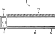
In prior art, module backlight can be divided into down straight aphototropism mode set and side-light type module backlight generally.See also Figure 1A and Figure 1B, Figure 1A is the synoptic diagram that illustrates the down straight aphototropism mode set 1 of prior art, and Figure 1B then illustrates the synoptic diagram of the side-light type module 2 backlight of prior art.Shown in Figure 1A, the light that the light-emitting component 10 that down straight aphototropism mode set 1 comprises is sent directly penetrates printing opacity unit T1 or the element 12 that is reflected reflects and then penetrate printing opacity unit T1, causes the user who is positioned at reflecting element 12 opposite sides to can be observed light source.In addition, shown in Figure 1B, the light incident LGP 24 that the light-emitting component 20 of the side of side-light type module 2 backlight is sent.LGP 24 can be with the light printing opacity unit T2 that leads, or through reflecting element 22 further light is reflexed to printing opacity unit T2.Therefore, the user who is positioned at reflecting element 22 opposite sides can be observed light source.In addition, side-light type module 2 backlight also has shade 26 and spills from module backlight side to prevent light source.
In order to make light can be uniformly distributed in above-mentioned printing opacity unit, let the user can not observe tangible brightness disproportionation, down straight aphototropism mode set need possess a plurality of homodisperse light-emitting components, and side-light type module backlight then need be provided with LGP so that uniform source of light to be provided.The trend of module backlight is constantly to reduce fluorescent tube quantity and reduce the slimming that module thickness backlight is beneficial to electronic installation and module backlight in recent years.Because fluorescent tube of many fluorescent tubes design demand a greater number of down straight aphototropism mode set and bigger light mixing distance, the design of this kind module backlight is unfavorable for purpose of thinness.To side-light type module backlight, though its required light-emitting component quantity is few than the quantity of down straight aphototropism mode set, yet the expensive of LGP makes that side-light type module cost backlight is difficult to reduce.Therefore if can omit the LGP of side-light type module backlight, can solve the problem of slimming and cost simultaneously.
[summary of the invention]
One of the present invention category is to provide a kind of side-light type module backlight that omits LGP, to solve the problem of prior art.
The present invention provides a kind of module backlight, comprises:
One first reflex housing is arranged at a side of this module backlight, and this first reflex housing has one
First reflecting curved surface, and this first reflecting curved surface has one first focus;
One first light emitting diode is arranged on this first focus, this first light-emitting diodes pipe
One first light emission face is arranged towards this first reflecting curved surface; And
One first reflector plate is arranged at a bottom surface of this module backlight;
Wherein, The light that this first light emission face of this first light emitting diode of this first reflecting curved surface reflection is sent to be forming one first source of parallel light, and this this first source of parallel light of first reflector plate reflection is with the light-emitting area of this first source of parallel light guiding with respect to this bottom surface.
The present invention also provides a kind of electronic installation, comprises:
One printing opacity unit; And
One module backlight, in abutting connection with this printing opacity unit, this module backlight comprises:
One first reflex housing is arranged at a side of this module backlight, and this first reflex housing has
One first reflecting curved surface, and this first reflecting curved surface has one first focus;
One first light emitting diode is arranged on this first focus this first light emitting diode
Has one first light emission face towards this first reflecting curved surface; And
One first reflector plate is arranged at a bottom surface of this module backlight;
Wherein, the light that this first light emission face of this first light emitting diode of this first reflecting curved surface reflection is sent to be forming one first source of parallel light, and this this first source of parallel light of first reflector plate reflection is with this this printing opacity unit of first source of parallel light guiding.
According to a specific embodiment, module backlight of the present invention comprises first reflex housing, first light emitting diode and first reflector plate.First reflex housing is a side that is arranged at module backlight, and has first reflecting curved surface on it.First light emitting diode is to be arranged on the focus of first reflecting curved surface, and the light emission face of first light emitting diode can be towards first reflecting curved surface.First reflecting surface is the bottom surface that is arranged at module backlight.
In this specific embodiment; The light that the light emission face of first light emitting diode is launched can be formed first reflector plate of source of parallel light towards the bottom surface by the reflection of first reflecting curved surface, and first reflector plate then can reflect source of parallel light towards the light-emitting area with respect to the bottom surface.
Another category of the present invention is to provide a kind of electronic installation, and its module backlight can omit LGP, therefore can solve the problem of prior art.
According to a specific embodiment, electronic installation of the present invention comprises printing opacity unit and module backlight, and wherein, module backlight is in abutting connection with the printing opacity unit.Module backlight can comprise first reflex housing, first light emitting diode and first reflector plate.First reflex housing is a side that is arranged at module backlight, and has first reflecting curved surface on it.First light emitting diode is to be arranged on the focus of first reflecting curved surface, and the light emission face of first light emitting diode can be towards first reflecting curved surface.In addition, first reflecting surface is the bottom surface that is arranged at module backlight.
In this specific embodiment; The light that the light emission face of first light emitting diode is launched can be formed first reflector plate of source of parallel light towards the bottom surface by the reflection of first reflecting curved surface, and first reflector plate then can reflect source of parallel light and also further penetrate the printing opacity unit towards the printing opacity unit.
Can graphicly further be understood by following detailed Description Of The Invention and appended about advantage of the present invention and spirit.
[description of drawings]
Figure 1A is the synoptic diagram that illustrates the down straight aphototropism mode set of prior art.
Figure 1B is the synoptic diagram that illustrates the side-light type module backlight of prior art.
Fig. 2 is the synoptic diagram that illustrates according to the electronic installation of a specific embodiment of the present invention.
Fig. 3 is the synoptic diagram that illustrates according to the electronic installation of another specific embodiment of the present invention.
Fig. 4 is the synoptic diagram that illustrates according to the electronic installation of another specific embodiment of the present invention.
1: down straight aphototropism mode set 2: side-light type module backlight
10,20: light-emitting component T1, T2: the printing opacity unit
12,22: reflecting element 24: LGP
26: shade
3,4,5: electronic installation 30,40,50: printing opacity unit
32,42,52: module backlight
320,420,520: the first reflex housings
322,422,522: the first light emitting diodes
324,424,524: the first reflector plates
3200,4200,5200: the first reflecting curved surfaces
3220,4220,5220: the first light emission faces
3240,4240: reflection configuration
528: the second light emitting diodes of 526: the second reflex housings
5260: the second reflecting curved surfaces of 530: the second reflector plates
5280: the second light emission faces
[embodiment]
See also Fig. 2, Fig. 2 is the synoptic diagram that illustrates according to the electronic installation 3 of a specific embodiment of the present invention.As shown in Figure 2, electronic installation 3 can comprise printing opacity unit 30 and module backlight 32, and wherein, module 32 backlight is in abutting connection with printing opacity unit 30.In practice, electronic installation 3 can be LCD, and printing opacity unit 30 can be liquid crystal panel, yet the present invention is not as limit.
In this specific embodiment, module 32 backlight comprises first reflex housing 320, first light emitting diode 322 and first reflector plate 324.First reflex housing 320 is sides that are arranged at module 32 backlight, and first reflecting curved surface 3200 is set on it.First reflex housing 320 that note that this specific embodiment is identical substantially with the shape of first reflecting curved surface 3200, yet in practice, first reflex housing 320 and first reflecting curved surface 3200 are not limited to identical shaped.
First reflecting curved surface 3200 is the curved surfaces with a focus, and first light emitting diode 322 can be arranged on this focus.First light emitting diode 322 can have light-emitting window, that is the first light emission face 3220 is with luminous towards specific direction.In this specific embodiment, the first light emission face 3220 is in the face of first reflecting curved surface 3200, so the light that first light emitting diode is sent can be advanced towards first reflecting curved surface 3200.
Because first light emitting diode 322 is to be arranged on the focus of first reflecting curved surface 3200, so its light that sends can form source of parallel light after by 3200 reflections of first reflecting curved surface and in module 32 backlight, advances.First reflector plate 324 is to be arranged at the bottom surface of module 32 backlight and with respect to printing opacity unit 30, and when source of parallel light was incident to first reflector plate 324, first reflector plate 324 can reflect source of parallel light and with its guiding printing opacity unit 30.Therefore, the user can observe light source in the opposite side of printing opacity unit 30.
In order to let light source can be distributed in each corner of printing opacity unit 30 equably; First reflector plate 324 of this specific embodiment its near a side of first reflex housing 320 away from printing opacity unit 30; And first reflector plate 324 its away from a side of first reflex housing 320 near printing opacity unit 30, its relative position is as shown in Figure 2.By this kind inclined design, can solve the uneven problem of distribution of light sources, and let the user observe uniform brightness.
In sum, module backlight of the present invention side direction light source capable of using mode provides average light-source brightness to electronic installation, and the design that can omit LGP, and then significantly reduces the production cost of module backlight.
In addition, in this specific embodiment, reflection configuration 3240 can further be set on first reflector plate 324 with help reflection source of parallel light and with its guiding printing opacity unit 30.Note that the shape of reflection configuration 3240 and be configured in the practice and can decide, be not limited to the cited specific embodiment of the present invention according to user or deviser's demand.The quantity of reflection configuration 3240 can influence the light-source brightness that reflexes to printing opacity unit 30; For example; The brightness of the light source that the light source that the zone reflected of reflection configuration 3240 density high (that is quantity is more in the unit area) can be reflected than reflection configuration 3240 low density zones is for high.Therefore; Can be provided with away from the zone of light emitting source on first reflector plate 324 that the zone near light emitting source can be provided with less reflection configuration 3240 with average light source distribution on the more reflection configuration 3240 and first reflector plate 324, and then let the user observe uniform brightness.In practice, reflection configuration 3240 the punching presses capable of using or mode of injection molding is made, however the present invention is not as limit.
In this specific embodiment, first reflector plate 324 is to be plane and to be obliquely installed in the bottom surface of module 32 backlight, yet the shape of first reflector plate 324 and configuration can be decided according to user or deviser's demand.For example, see also Fig. 3, Fig. 3 is the synoptic diagram that illustrates according to the electronic installation 4 of another specific embodiment of the present invention.
As shown in Figure 3, electronic installation 4 comprises printing opacity unit 40 and module backlight 42, and wherein, module 42 backlight is in abutting connection with printing opacity unit 40.Likewise, module 42 backlight comprises first reflex housing 420, first light emitting diode 422 and first reflector plate 424.
This specific embodiment does not exist together with a last specific embodiment; First reflector plate 424 that is this specific embodiment is to be the curved surface shape; And its side away from first reflex housing 420 (in this can second side representative) than its side (can the representative of first side) in this near first reflex housing 420 also near printing opacity unit 40, therefore can be further the average light-source brightness of printing opacity unit 40.Other unit that note that this specific embodiment are identical substantially with the function of above-mentioned specific embodiment, so repeat no more in this.In addition, the curvature of first reflector plate 424 of this specific embodiment can be decided according to user or deviser's demand in practice, is not limited to the cited specific embodiment of the present invention.
Likewise; On first reflector plate 424 of this specific embodiment reflection configuration 4240 can be set; In addition, the zone near light emitting source that the more reflection configuration 4240 and first reflector plate 424 can be set, the zone away from light emitting source of first reflector plate 424 can be provided with less reflection configuration 4240 with average light source Luminance Distribution.
In practice, the module backlight of above-mentioned specific embodiment can comprise at least one group of above reflex housing, light emitting diode and reflector plate, it is provided to the light source of more large-scale electronic installation (for example, large scale liquid crystal flat-panel screens) have than mean flow rate.For example, see also Fig. 4, Fig. 4 is the synoptic diagram that illustrates according to the electronic installation 5 of another specific embodiment of the present invention.As shown in Figure 4, electronic installation 5 comprises printing opacity unit 50 and module backlight 52, wherein, and module backlight 52 contiguous printing opacity unit 50.
In this specific embodiment, module 52 backlight comprises first reflex housing 520, first light emitting diode 522, first reflector plate 524, second reflex housing 526, second light emitting diode 528 and second reflector plate 530.First reflex housing 520 is sides that are arranged at module 52 backlight, and it has first reflecting curved surface 5200, and first light emitting diode 522 is arranged on the focus of first reflecting curved surface 5200.In addition, the first light emission face 5220 of first light emitting diode 522 can be towards first reflecting curved surface 5200.First reflector plate 524 is the bottom surfaces that are arranged at module 52 backlight, and first reflector plate 524 away from a side of first reflex housing 520 than first reflector plate 524 near a side of first reflex housing 520 also near printing opacity unit 50.It is identical substantially with above-mentioned specific embodiment that first reflex housing 520, first light emitting diode 522 and first reflector plate 524 provide the flow process of light source to printing opacity unit 50, so repeat no more in this.
In addition, second reflex housing 526, second light emitting diode 528 and second reflector plate 530 are to be relative configuration with above-mentioned first reflex housing 520, first light emitting diode 522 and first reflector plate 524.That is second reflex housing 526 is to be provided with respect to the opposite side of first reflex housing 520 at module 52 backlight.Second reflex housing 526 has second reflecting curved surface 5260, and second light emitting diode 528 is to be arranged on the focus of second reflecting curved surface 5260.The second light emission face 5280 of second light emitting diode 528 is towards second reflecting curved surface 5260.Second reflector plate 530 is the bottom surfaces that are arranged at module 52 backlight, and second reflector plate 530 away from a side of second reflex housing 526 than second reflector plate 530 near a side of second reflex housing 526 also near printing opacity unit 50.
In this specific embodiment; It is to provide the flow process of light source identical substantially with first reflex housing 520, first light emitting diode 522 and first reflector plate 524 that second reflex housing 526, second light emitting diode 528 and second reflector plate 530 provide the flow process of light source; Only its light direction of advancing is variant, so repeat no more in this.
In sum; The module backlight of this specific embodiment can comprise at least one group of reflex housing, light emitting diode and reflector plate so that the uniform source of light of large-scale electronic installation such as large scale liquid crystal display to be provided; And in practice; The quantity of reflex housing, light emitting diode and reflector plate is not limited to the cited specific embodiment of this instructions, and end is seen user or deviser's demand and decided.
In another specific embodiment, reflection configuration also can be set on first reflector plate 524 and second reflector plate 530 to assist the reflection source of parallel light to printing opacity unit 50.Likewise, more reflection configuration can be set with average light source Luminance Distribution away from the zone away from second reflex housing 526 on regional and second reflector plate 530 of first reflex housing 520 on first reflector plate 524.
Compared to prior art, module backlight of the present invention is to utilize light emitting diode to cooperate reflex housing to produce source of parallel light, then to relend by reflector plate source of parallel light to be reflexed on the specific light-emitting area.Reflector plate can be inclined to set so that module backlight provides uniform source of light.Because module backlight of the present invention is with the side-light type light source and cooperates reflex housing so that source of parallel light to be provided, so can omit the setting of LGP.Therefore, module backlight of the present invention has the characteristics of using less light-emitting component and omitting LGP concurrently, and then the purpose that is beneficial to slimming and reduces cost.
By the detailed description of above preferred embodiment, be to hope to know more to describe characteristic of the present invention and spirit, and be not to come category of the present invention is limited with the above-mentioned preferred embodiment that is disclosed.On the contrary, its objective is that hope can contain in the category of claim of being arranged in of various changes and tool equality institute of the present invention desire application.Therefore, the category of the claim that the present invention applied for should be done the broadest explanation according to above-mentioned explanation, contains the arrangement of all possible change and tool equality to cause it.