CN101951848A - Implant equipped for nerve location and method of use - Google Patents
Implant equipped for nerve location and method of use Download PDFInfo
- Publication number
- CN101951848A CN101951848A CN2008801273329A CN200880127332A CN101951848A CN 101951848 A CN101951848 A CN 101951848A CN 2008801273329 A CN2008801273329 A CN 2008801273329A CN 200880127332 A CN200880127332 A CN 200880127332A CN 101951848 A CN101951848 A CN 101951848A
- Authority
- CN
- China
- Prior art keywords
- implant
- neuromechanism
- telecommunication
- securing member
- bone
- Prior art date
- Legal status (The legal status is an assumption and is not a legal conclusion. Google has not performed a legal analysis and makes no representation as to the accuracy of the status listed.)
- Granted
Links
Images


Classifications
-
- A—HUMAN NECESSITIES
- A61—MEDICAL OR VETERINARY SCIENCE; HYGIENE
- A61B—DIAGNOSIS; SURGERY; IDENTIFICATION
- A61B5/00—Measuring for diagnostic purposes; Identification of persons
- A61B5/48—Other medical applications
- A61B5/4887—Locating particular structures in or on the body
- A61B5/4893—Nerves
-
- A—HUMAN NECESSITIES
- A61—MEDICAL OR VETERINARY SCIENCE; HYGIENE
- A61B—DIAGNOSIS; SURGERY; IDENTIFICATION
- A61B17/00—Surgical instruments, devices or methods
- A61B17/56—Surgical instruments or methods for treatment of bones or joints; Devices specially adapted therefor
- A61B17/58—Surgical instruments or methods for treatment of bones or joints; Devices specially adapted therefor for osteosynthesis, e.g. bone plates, screws or setting implements
- A61B17/68—Internal fixation devices, including fasteners and spinal fixators, even if a part thereof projects from the skin
- A61B17/84—Fasteners therefor or fasteners being internal fixation devices
- A61B17/86—Pins or screws or threaded wires; nuts therefor
- A61B17/866—Material or manufacture
-
- A—HUMAN NECESSITIES
- A61—MEDICAL OR VETERINARY SCIENCE; HYGIENE
- A61B—DIAGNOSIS; SURGERY; IDENTIFICATION
- A61B5/00—Measuring for diagnostic purposes; Identification of persons
- A61B5/24—Detecting, measuring or recording bioelectric or biomagnetic signals of the body or parts thereof
-
- A—HUMAN NECESSITIES
- A61—MEDICAL OR VETERINARY SCIENCE; HYGIENE
- A61B—DIAGNOSIS; SURGERY; IDENTIFICATION
- A61B5/00—Measuring for diagnostic purposes; Identification of persons
- A61B5/24—Detecting, measuring or recording bioelectric or biomagnetic signals of the body or parts thereof
- A61B5/316—Modalities, i.e. specific diagnostic methods
- A61B5/389—Electromyography [EMG]
-
- A—HUMAN NECESSITIES
- A61—MEDICAL OR VETERINARY SCIENCE; HYGIENE
- A61B—DIAGNOSIS; SURGERY; IDENTIFICATION
- A61B17/00—Surgical instruments, devices or methods
- A61B17/56—Surgical instruments or methods for treatment of bones or joints; Devices specially adapted therefor
- A61B17/58—Surgical instruments or methods for treatment of bones or joints; Devices specially adapted therefor for osteosynthesis, e.g. bone plates, screws or setting implements
- A61B17/68—Internal fixation devices, including fasteners and spinal fixators, even if a part thereof projects from the skin
- A61B17/70—Spinal positioners or stabilisers, e.g. stabilisers comprising fluid filler in an implant
- A61B17/7001—Screws or hooks combined with longitudinal elements which do not contact vertebrae
- A61B17/7032—Screws or hooks with U-shaped head or back through which longitudinal rods pass
Landscapes
- Health & Medical Sciences (AREA)
- Life Sciences & Earth Sciences (AREA)
- Surgery (AREA)
- Veterinary Medicine (AREA)
- Animal Behavior & Ethology (AREA)
- Public Health (AREA)
- Engineering & Computer Science (AREA)
- Biomedical Technology (AREA)
- Heart & Thoracic Surgery (AREA)
- Medical Informatics (AREA)
- Molecular Biology (AREA)
- General Health & Medical Sciences (AREA)
- Biophysics (AREA)
- Physics & Mathematics (AREA)
- Pathology (AREA)
- Orthopedic Medicine & Surgery (AREA)
- Neurology (AREA)
- Nuclear Medicine, Radiotherapy & Molecular Imaging (AREA)
- Surgical Instruments (AREA)
- Prostheses (AREA)
Abstract
本发明描述了外科植入物,外科植入物被装备以在植入期间和之后提供神经病学数据。神经病学监测确保了在最小地侵害神经结构的条件下准确地插入植入物。该植入物包括至少一个导电区域,该至少一个导电区域用于确定神经相对于植入物的距离和方向。
This invention describes a surgical implant equipped to provide neurological data during and after implantation. Neurological monitoring ensures accurate insertion of the implant with minimal damage to neural structures. The implant includes at least one conductive region for determining the distance and orientation of the nerve relative to the implant.
Description
技术领域technical field
本发明概括地涉及外科植入物及其插入方法,具体地涉及外科植入物以及在植入物的外科插入期间使用电势来避免神经损伤的方法,更具体地涉及具有至少一个导电区域的植入物,该导电区域用于确定神经相对于该植入物的距离和方向。The present invention relates generally to surgical implants and methods of insertion thereof, in particular to surgical implants and methods of using electrical potential to avoid nerve damage during surgical insertion of implants, and more particularly to implants having at least one electrically conductive region implant, the conductive area is used to determine the distance and direction of the nerve relative to the implant.
背景技术Background technique
椎弓根螺钉(pedicle screw)固定已经成为脊柱的三种脊椎的坚固内固定(rigid internal fixation)最受青睐的方式。由于基于椎弓根螺钉的仪器系统的优越的生物力学性能以及更高的骨性融合率,所以基于椎弓根螺钉的仪器系统的使用在过去的三十年里稳步增长。然而,当植入这些螺钉时对椎弓根内侧壁或椎体的侵害带有伤害神经结构、血管结构以及内脏结构的危险。例如,在放置期间,螺钉体能够穿过脊椎皮质(vertebral cortex),对脊髓造成直接损伤或对附近的神经(脊柱旁神经(para-spinal nerve)、神经根等)造成伤害。Pedicle screw fixation has become the most favored method for rigid internal fixation of the three vertebrae of the spine. The use of pedicle screw-based instrumentation has grown steadily over the past three decades due to their superior biomechanical properties and higher rates of bony fusion. However, invasion of the medial pedicle wall or vertebral body when implanting these screws carries the risk of injuring neural, vascular, and visceral structures. For example, during placement, the screw body can pass through the spinal cortex, causing direct damage to the spinal cord or causing damage to nearby nerves (para-spinal nerves, nerve roots, etc.).
将椎弓根螺钉插入脊柱椎弓根内,骨刺(bony process)从椎体起向后突出,并且通过相对于椎骨纵向放置的连接杆或者连接板稳定椎弓根螺钉。椎弓根螺钉结构的生物力学测试已经证明,螺钉置于椎弓根的峡部以获得对于阻止螺钉拔出必需的适当的皮层抓牢是至关重要的。因此,外科上椎弓根螺钉的放置技术要求较高。需要广泛训练以及对细节的格外注意以避免伤害病人。Pedicle screws are inserted into the pedicles of the spine, bony processes protruding posteriorly from the vertebral body, and the pedicle screws are stabilized by connecting rods or plates placed longitudinally relative to the vertebrae. Biomechanical testing of pedicle screw constructs has demonstrated that screw placement in the isthmus of the pedicle is critical to obtain the proper cortical grip necessary to prevent screw extraction. Therefore, the placement of surgical upper pedicle screws requires high technical requirements. Extensive training and great attention to detail are required to avoid injuring the patient.
不管外科医生的技能如何,错误地放置椎弓根螺钉是常见的。因此,已经研发了许多计算机辅助外科导航系统以及手术中的X光透视检查技术以提高椎弓根螺钉放置的准确率;然而,这些成像系统具有某些缺点。X光透视检查程序增加了对病人、手术室工作人员以及外科医生的辐射暴露量。计算机辅助导航系统需要手术前CT扫描,手术前CT扫描将病人暴露于附加的辐射,一些外科医生认为其太耗费时间和太复杂而难以证明其适于常规使用。时常地,这些成像系统在分辨率方面受到限制,即椎弓根的内侧壁的裂口可能是不可探测的。Misplacement of pedicle screws is common regardless of the surgeon's skill. Therefore, many computer-aided surgical navigation systems and intraoperative fluoroscopy techniques have been developed to improve the accuracy of pedicle screw placement; however, these imaging systems have certain disadvantages. Fluoroscopy procedures increase radiation exposure for patients, operating room staff, and surgeons. Computer-aided navigation systems require pre-operative CT scans, which expose the patient to additional radiation, and are considered by some surgeons to be too time-consuming and complicated to justify for routine use. Oftentimes, these imaging systems are limited in resolution, ie, breaches in the medial wall of the pedicle may not be detectable.
尽管所有上述系统可以使外科医生能够确定螺钉是否事实上已经撕裂了椎弓根壁,但是仅在已经植入了接骨螺钉之后才能发现这个裂口或裂缝。这需要在螺钉已经造成损害以后取回和重新插入螺钉。由安装装备(K线、牵张系统、钻头、锥子、刮匙等)造成的椎弓根壁破坏通常不会造成神经损伤。置于椎弓根螺钉开口内的电子测试探针可能探测不出由安装装备产生的较小裂缝或裂痕。大多数重大的神经损伤发生在将椎弓根螺钉植入骨性结构内期间。在安装椎弓根螺钉期间,螺钉的一部分通过由安装装备产生的裂痕可能不注意地接触神经。这可能引起神经损伤、感觉缺陷或者疼痛。因此,在外科领域需要这样一种系统,其能够在植入过程期间提供适合的紧固件放置,以主动地越过或绕过神经以防止损伤或不适合的螺钉放置。While all of the above systems can enable the surgeon to determine whether the screw has in fact torn the pedicle wall, this breach or fissure can only be discovered after the bone screw has been implanted. This requires retrieval and reinsertion of the screw after the screw has caused damage. Disruption of the pedicle wall by installation equipment (K-wires, distraction systems, drills, awls, curettes, etc.) usually does not cause neurological damage. Electronic test probes placed in pedicle screw openings may not detect small cracks or fissures created by the mounting equipment. Most significant nerve injury occurs during the placement of pedicle screws into bony structures. During installation of a pedicle screw, a portion of the screw may inadvertently contact the nerve through a tear created by the installation equipment. This can cause nerve damage, sensory deficits, or pain. Therefore, there is a need in the surgical field for a system that can provide proper fastener placement during implantation procedures to actively pass over or around nerves to prevent damage or improper screw placement.
现有技术current technology
授予Fizzell等人的第2,704,064号美国专利公开了被称为神经外科刺激器的装置,其用于区分神经。该装置包括两个探针,两个探针被置于身体上待被刺激的某一区域,操作的外科医生等待对施加的电流的反应(颤搐)。如果观察到反应,外科医生避免在该特定区域切割以防止对神经的无意损伤。例如,该装置可用于肿瘤切除,由于其能够区分肿瘤组织与周围的神经。Fizzel装置的功能取决于电流的人工调节和使用者的视觉观察。这就需要外科医生连续地观察肌肉的反应;然而,当使用麻醉时,肌肉的反应可能被衰减至外科医生不能察觉到的地步。因此,使用这种装置的外科医生仍然可能损伤神经。US Patent No. 2,704,064 to Fizzell et al. discloses a device known as a neurosurgical stimulator for differentiating nerves. The device consists of two probes that are placed on a certain area of the body to be stimulated, and the operating surgeon waits for a response (twitch) to the applied current. If a reaction is observed, the surgeon avoids cutting in that particular area to prevent inadvertent damage to the nerve. For example, the device can be used for tumor resection due to its ability to distinguish tumor tissue from surrounding nerves. The function of the Fizzel device depends on the manual adjustment of the electric current and the visual observation of the user. This requires the surgeon to continuously observe the muscle response; however, when anesthesia is used, the muscle response may be attenuated to the point where the surgeon cannot detect it. Therefore, a surgeon using such a device could still injure a nerve.
授予Raymond等人的第5,284,153号美国专利公开了一种方法,其中神经刺激器用于在外科手术期间定位神经、识别神经的功能以及预防神经的无意切割。神经定位器包括:与电源相连的外科探针,用于探测神经对电刺激的反应的设备以及自动调整刺激大小的装置。US Patent No. 5,284,153 to Raymond et al. discloses a method in which a neurostimulator is used to locate a nerve, identify the function of the nerve, and prevent inadvertent cutting of the nerve during a surgical procedure. A nerve locator consists of a surgical probe connected to a power source, a device for detecting the nerve's response to electrical stimulation, and a device for automatically adjusting the stimulus size.
授予Neubardt的第5,196,015号和第5,474,558号美国专利公开了用于脊柱椎弓根螺钉插入的系统和步骤,以降低由不适合的螺钉放置造成神经损伤的可能性。螺钉开口起始于一部分的骨骼区域,例如,腰椎的椎弓根,将某一幅度的电势施加到开口的内表面,同时观察病人的神经系统反应,例如腿颤搐。继续形成开口同时施加电势,直到获得期望的洞深度,而没有对电势的神经系统反应。当在最后方向形成螺钉开口时,在观察病人对电势的反应之后,正形成螺钉开口的方向被改变为不同于最后方向的方向。‘558号专利进一步公开了包括把手和可拆卸的安装装备(探针部件、攻螺丝部件以及驱动器)的工具,该可拆卸的安装装备从把手起延伸,分别用于在骨骼组织形成开口、攻螺丝以及插入螺钉。布置在把手内部的刺激电路产生预定水平的电势。与本发明不同,电势被施加给可拆卸的安装部件,而不是植入物本身。因此,安装装备测量该装备与最近的神经的距离。这会在安装装备与植入物尖端之间产生贴近间隙,该贴近间隙能够导致植入物危险地接近神经结构或侵犯神经结构。US Patent Nos. 5,196,015 and 5,474,558 to Neubardt disclose systems and procedures for spinal pedicle screw insertion to reduce the likelihood of nerve injury from improper screw placement. A screw opening is initiated in a portion of the bony region, eg, the pedicle of the lumbar spine, and an electrical potential of a certain magnitude is applied to the inner surface of the opening while the patient's neurological response, such as a leg twitch, is observed. Formation of the opening is continued while applying the potential until the desired hole depth is obtained without neurological response to the potential. When the screw opening is formed in the final direction, the direction in which the screw opening is being formed is changed to a direction different from the final direction after observing the patient's response to the electric potential. The '558 patent further discloses a tool that includes a handle and removable mounting equipment (probe assembly, tapping screw assembly, and driver) extending from the handle for forming openings in bone tissue, tapping, respectively. screws and insert screws. A stimulation circuit disposed inside the handle generates a predetermined level of electrical potential. Unlike the present invention, the electrical potential is applied to the removable mounting part, not the implant itself. Therefore, the installation device measures the distance of the device to the nearest nerve. This creates an approximation gap between the mounting equipment and the tip of the implant, which can lead to the implant being dangerously close to or encroaching on the nerve structure.
授予Bolger等人的第6,796,985号美国专利公开了用于钻骨的方法和装备,特别是用于安装椎弓根螺钉的方法和装备。该装备包括钻孔器具、电脉冲源以及用于将电脉冲源与钻孔器具相连的连接器。该装备还包括至少一个用于探测肌肉信号的传感器,用于探测肌肉信号的传感器在钻孔之前和钻孔期间被植入肌肉中或者被置于肌肉附近的皮肤上。如果至少一个传感器探测到与连接至钻孔器具的电脉冲源关联的肌肉信号,那么就发出警报。与本发明不同,’985号专利中的植入物没有包括至少一个导电区域,当植入物被植入骨结构时,该至少一个导电区域能够提供用于测试骨性结构(例如,椎弓根)的完整性以及任何邻近的神经结构的位置的刺激信号。US Patent No. 6,796,985 to Bolger et al. discloses methods and apparatus for drilling bone, particularly for installing pedicle screws. The kit includes a drilling tool, a source of electrical pulses, and a connector for connecting the source of electrical pulses to the drilling tool. The equipment also includes at least one sensor for detecting muscle signals, the sensor for detecting muscle signals being implanted in the muscle or placed on the skin adjacent to the muscle before and during drilling. An alarm is sounded if at least one sensor detects a muscle signal associated with a source of electrical pulses connected to the drilling instrument. Unlike the present invention, the implant in the '985 patent does not include at least one conductive region that would provide for testing of bony structures (e.g., vertebral arches) when the implant is implanted in the bony structure. root) integrity and the location of any adjacent neural structures to stimulate the signal.
Pimenta等人的、公开号为2005/0149035的美国申请公开了外科接入系统,包括组织牵张装置与组织回缩装置,二者都可以装备一个或多个电极,一个或多个电极用于在至外科目标位置的手术通道建立之前、期间和之后探测神经结构的存在(以及可选地到神经结构的距离和/或方向)。类似地,Gharib等人的、公开号为2005/0075578的美国申请公开了用于执行外科操作和评价的系统和相关方法,包括使用基于神经生理的监测以便于:(a)确定相对于在接近外科目标位置过程中使用的外科仪器的神经方向和神经邻近度;(b)在外科手术之前、期间或之后评价神经或神经根的病理(健康状况或状态);和/或(c)在放置椎弓根螺钉之前、期间或之后,评价椎弓根的完整性。U.S. Application Publication No. 2005/0149035 to Pimenta et al. discloses a surgical access system comprising a tissue distraction device and a tissue retraction device, both of which may be equipped with one or more electrodes for The presence (and optionally the distance and/or direction to the neural structure) of the neural structure is detected before, during, and after establishment of the surgical pathway to the surgical target site. Similarly, U.S. Application Publication No. 2005/0075578 to Gharib et al. discloses systems and related methods for performing surgical procedures and evaluations, including the use of neurophysiologically based monitoring to: (a) determine relative Nerve orientation and nerve proximity of surgical instruments used during surgical target placement; (b) evaluation of nerve or nerve root pathology (health or state) before, during, or after surgical procedures; and/or (c) prior to placement Pedicle integrity was assessed before, during, or after pedicle screws.
与本发明不同,在Pimenta等人和Gharib等人的专利申请中,向给定神经提供刺激的电极位于外科手术附件上。外科手术附件指的是用于产生至外科手术目标位置的手术通道的装置或组件(例如,K线、扩张导管系统、牵张系统和/或回缩系统)或者用于评价椎弓根的完整性的装置或组件(通过螺钉测试探针)。该系统还在附件上的正极的位置与植入物之间提供贴近间隙,该贴近间隙能够导致植入物有危险地接近或侵犯神经结构。另外,仅在椎弓根螺钉已经被完全地植入骨性结构中之后,椎弓根测试探针才能施加刺激信号以测试椎弓根的内侧壁的完整性。相反地,本发明公开了形成于植入物本身的远端上的至少一个导电区域。这种区别是关键的,因为在植入物被固定就位时这些导电区域能够施加刺激信号以测试骨性结构的完整性和/或神经结构的邻近性(方向、距离)。因此,在任何神经病学损伤产生之前,即可避开由外科手术附件暴露的任何神经结构或那些外科手术附件未探测到的任何神经结构。Unlike the present invention, in the Pimenta et al. and Gharib et al. patent applications, the electrodes that provide stimulation to a given nerve are located on the surgical appendage. Surgical accessories refer to devices or assemblies used to create surgical access to surgical target sites (eg, K-wires, dilation catheter systems, distraction systems, and/or retraction systems) or to assess pedicle integrity. Sexual devices or components (via screw test probes). The system also provides close clearance between the location of the positive pole on the appendage and the implant, which can cause the implant to dangerously approach or encroach on neural structures. Additionally, only after the pedicle screw has been fully implanted in the bony structure can the pedicle test probe apply the stimulation signal to test the integrity of the medial wall of the pedicle. Rather, the present invention discloses at least one conductive region formed on the distal end of the implant itself. This distinction is critical because these conductive areas can apply stimulation signals to test the integrity of bony structures and/or the proximity (direction, distance) of neural structures when the implant is held in place. Thus, any neural structures exposed by the surgical accessories or not detected by those surgical accessories can be avoided before any neurological damage occurs.
发明内容Contents of the invention
本发明的目的是提供适于目标植入位置的神经生理监测的植入物。所述植入物包括本体部件,所述本体部件具有近端和远端,其中所述远端被构造并布置为用于固定至外科目标位置。所述远端包括至少一个区域,所述至少一个区域被构造并布置为释放有效数量的电势从而在位于附近的任何神经结构中产生刺激电信号。在将所述植入物固定在活体内期间,所述刺激电信号提供了神经结构相对于所述远端的距离和/或方向。因此,在手术期间,可以操作所述植入物,从而能够避开任何神经结构。It is an object of the present invention to provide an implant suitable for neurophysiological monitoring of the intended implantation site. The implant includes a body member having a proximal end and a distal end, wherein the distal end is constructed and arranged for fixation to a surgical target site. The distal end includes at least one region constructed and arranged to deliver an effective amount of electrical potential to generate stimulating electrical signals in any neural structures located nearby. During fixation of the implant in vivo, the stimulating electrical signal provides the distance and/or direction of the neural structure relative to the distal end. Thus, during surgery, the implant can be manipulated so that any neural structures can be avoided.
因此,本发明的一个目的是提供植入物,所述植入物被构造并布置为用于固定至外科目标区域,从而可以避开位于目标区域附近的或位于目标位置处的任何神经结构。It is therefore an object of the present invention to provide an implant constructed and arranged for fixation to a surgical target area such that any neural structures located near or at the target area can be avoided.
本发明的另一目的是提供使神经损伤减至最小的系统,从而提供较少的手术后疼痛。Another object of the present invention is to provide a system that minimizes nerve damage, thereby providing less post-operative pain.
本发明的另一目的是提出一种具有警报装置的植入系统,当所述植入物接近神经结构时,所述警报装置使用音频的和/或视频的反馈来指示外科医生。Another object of the present invention is to propose an implant system with an alarm device that uses audio and/or visual feedback to indicate to the surgeon when the implant is approaching neural structures.
本发明的另一目的是提出一种植入物,所述植入物对于病人允许更短的手术时间,减少的X射线暴露以及更少的并发症。Another object of the present invention is to propose an implant that allows shorter operative times, reduced X-ray exposure and fewer complications for the patient.
本发明的另一目的是提出一种植入系统,所述植入系统足够简单,以确保外科医生将日常地使用它。Another object of the invention is to propose an implant system that is simple enough to ensure that it will be used routinely by surgeons.
从结合附图进行的下面描述中,本发明的其他目的和优势将变得显而易见,其中,通过说明和实施例阐明了本发明的某些实施方式。附图构成了本说明书的一部分,包括本发明的示例性实施方式并且示出了本发明的各个目的和特征。Other objects and advantages of the invention will become apparent from the following description, taken in conjunction with the accompanying drawings, in which certain embodiments of the invention are set forth by way of illustration and example. The accompanying drawings constitute a part of this specification, include exemplary embodiments of the invention, and illustrate various objects and features of the invention.
附图说明Description of drawings
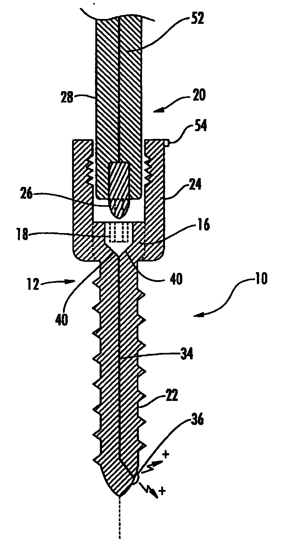
图1是根据本发明的一个实施方式的固定轴接骨螺钉的横截面图;Figure 1 is a cross-sectional view of a fixed shaft bone screw according to one embodiment of the present invention;
图2是根据本发明的另一实施方式的固定轴接骨螺钉的另一横截面图;以及2 is another cross-sectional view of a fixed-axis bone screw according to another embodiment of the present invention; and
图3是与用于执行植入物的植入的神经刺激器的组件通信的腰椎区域和接骨螺钉驱动器的侧视图。3 is a side view of the lumbar region and bone screw driver in communication with components of the neurostimulator for performing implantation of the implant.
具体实施方式Detailed ways
为了促进对本发明的原理的理解,现将参考附图所示的实施方式,使用特定语言来描述实施方式。然而,示出的实施方式仅是例示性的。可以理解,其并非意欲限定本发明的范围。示出的装置中的任何变化和进一步修改以及本文中示出的本发明原理的进一步应用被认为是与本发明相关领域的技术人员通常可以想到的。To promote an understanding of the principles of the invention, specific language will now be used to describe the embodiments with reference to the embodiments illustrated in the drawings. However, the illustrated embodiments are exemplary only. It is understood that no limitation of the scope of the invention is intended. Any changes and further modifications in the apparatus shown and further applications of the principles of the invention as set forth herein are deemed to occur to those skilled in the art to which the invention pertains normally.
现在参考图1-3,图1-3示出了适合于目标位置的神经生理监测的本发明的植入物10,在图1-3中,相同的元件的被通篇一致地标号。图1示出了植入物的一个非限定性的实例,这里其被描述为固定轴椎弓根或接骨螺钉。骨紧固件本体包括近端12和远端14。近端包括头部16,头部16带有被配置成接纳任何适合的驱动工具20的工具缺口18。远端包括螺纹杆22,螺纹杆22被设计成可旋转地与位于病人身体内所选目标位置处的骨骼相接合,例如椎弓根的峡部(参见图3)。至少部分椎弓根螺钉本体由可外科植入的以及导电的材料制成,包括但不限于钛、不锈钢等。Referring now to FIGS. 1-3 , which illustrate an
此处示出的骨紧固件是固定轴螺钉,其中螺钉的近端包括固定地连接至螺钉的头部的连接器部分24。然而,在不背离本发明的范围的条件下可以使用多轴向螺钉。也就是说,连接器能够沿杆的纵轴线L相对于螺钉的螺纹杆360度旋转并且能够进行由角度限定的角转动。在第5,797,911号美国专利中描述了适合的多轴向螺钉的一个实例,该专利通过引用并入本文。此外,如本领域公知的,锚部件的杆可以是插套管的也可以不是插套管的。The bone fastener shown here is a fixed shaft screw, wherein the proximal end of the screw includes a
构造和布置螺钉的连接器部分24,以形成通道,该通道被设计成可移除地接纳至少一个生物相容稳定部件(未示出),例如互连棒或板。如本领域公知的,连接器部分包括开口,开口被构造和布置成接纳紧定螺钉(未示出)。例如,紧定螺钉可以沿螺钉的连接器部分的纵轴线螺纹地降低以形成通道。通道变窄直到生物相容设备的外表面被夹在螺钉头与紧定螺钉之间。这起到将生物相容设备可靠地固定到螺钉上的作用。The
如上所述,植入物本体由导电材料制成,例如钛、不锈钢、或其他适合的具有足够强度来与骨骼接合的生物相容传导性金属材料。骨骼中的开口可以通过使用任何适合的技术和设备(例如钻头、锥子、或刮匙)事先形成。此外,在插入骨紧固件之前,可以对开口也可以不对开口攻螺纹。通过任何适合的驱动工具20(例如,螺钉驱动器)将骨紧固件插入椎弓根中的开口内。驱动工具在外科领域是众所周知的并且用于将骨紧固件可旋转地固定至在椎弓根内形成的开口中的期望的位置。As noted above, the implant body is made of a conductive material, such as titanium, stainless steel, or other suitable biocompatible conductive metallic material of sufficient strength to engage bone. The opening in the bone can be previously formed by using any suitable technique and equipment such as a drill, awl, or curette. Additionally, the openings may or may not be tapped prior to insertion of the bone fastener. The bone fastener is inserted into the opening in the pedicle by any suitable driving tool 20 (eg, a screw driver). Driving tools are well known in the surgical arts and are used to rotatably secure bone fasteners to desired positions in openings formed in the pedicles.
如上所述,骨紧固件的头部包括工具缺口18,工具缺口18被配置成接纳任何适合的驱动工具。根据本发明,驱动工具与神经刺激器电通信并且用于将电势沿骨紧固件的导电材料34传递至骨紧固件的远端。例如,驱动工具可以包括导电尖端26(六角形头、平头或十字头),导电尖端26被设计成符合螺钉头部中的工具缺口。螺钉的头部可以包括至少一个电接触40,至少一个电接触40被设计成与驱动工具的导电尖端配合。导电尖端26可通过与外科医生紧握的把手30相连的绝缘轴28保护。然后,将导电尖端放置在骨紧固件的头部内。As noted above, the head of the bone fastener includes a
螺钉的远端包括至少一个区域,构造并布置至少一个区域以释放在神经刺激器中产生的电势。例如,导电区域可以包括非绝缘的导电区域38(图2)或至少一个电极36(图1)等。从螺钉的远端释放的电势将在任何位于附近的神经结构中产生刺激电信号。可选地,正极可以沿至少可植入设备的外表面的一部分长度延伸,用于刺激神经结构。The distal end of the screw includes at least one region constructed and arranged to release an electrical potential generated in the neurostimulator. For example, the conductive region may include a non-insulated conductive region 38 (FIG. 2) or at least one electrode 36 (FIG. 1), among others. The electrical potential released from the distal end of the screw will generate stimulating electrical signals in any nearby neural structures. Optionally, the positive electrode may extend along at least a portion of the length of the outer surface of the implantable device for stimulating neural structures.
骨紧固件的导电材料用于在驱动工具与远端之间建立电通信。这可以通过任何适合的装置来实现。例如,导线或其他导电材料34(钛、钢等),其起始于骨紧固件的头部,沿螺钉的纵轴线L终止于释放电势的远端部分。例如,导电线芯材料可以电耦合到至少一个电极36,优选地正极,用于将电势电荷传递至任何位于附近的神经结构(例如,神经)。The conductive material of the bone fastener is used to establish electrical communication between the driving tool and the distal end. This can be accomplished by any suitable means. For example, a wire or other conductive material 34 (titanium, steel, etc.) that originates at the head of the bone fastener and terminates along the longitudinal axis L of the screw at the distal portion where the potential is released. For example, the conductive core material may be electrically coupled to at least one
如本领域公知的,由神经刺激监测装置产生的刺激电信号然后通过与神经刺激监测装置相连的适合的反应探测装置42探测。尽管图3中把反应探测装置示出为独立的,但是反应探测装置可以与神经刺激监测装置集成,参见图3。因此,神经刺激监测装置能够产生、探测和/或记录在神经结构本身中(神经的动作电位)或者相关的骨骼肌(肌肉动作电位)纤维中产生的刺激信号。一些神经刺激监测装置的实例包括,尽管不限于,本领域公知的肌电图(EMG)装置、体感(SSEP)装置和/或运动诱发电位(MEP)装置。The electrical stimulation signals generated by the nerve stimulation monitoring device are then detected by a suitable
使用标准技术,通过贴片或探针48将这些装置连接至病人,并且这些装置能够在用户显示屏46上提供可视警报信号和/或可听见的警报44,作为刺激电信号的幅度超过预定阈值的指示。一旦导电区域刺激,即对附近的神经去极化,反应探测装置将测量靠近植入物远端(例如,椎弓根螺钉的尖端)的神经结构的存在。当使骨紧固件前进穿过椎弓根时,诱发EMG反应所需的刺激将随与神经的距离变化。也就是说,导电区域与神经结构越近,诱发通过贴片或探针探测的刺激反应需要的刺激强度越小。可通过神经刺激监测装置中的计算机算法测量和监测刺激信号,或者可选地,可通过使用传统EMG监测装备由神经生理技术人员监测刺激信号。作为响应,算法将根据到神经的距离自动地调整提供给植入物的电势的幅度。此外,神经刺激监测装置应当包括控制器50,控制器50允许外科医生或神经生理技术人员选择性地节制用于产生刺激电信号的电势量。然后,探测装置监测并且评价刺激电信号,以提供神经的邻近性和/或神经的方向。当螺钉的远端部分刺激神经结构时,这表明神经结构在前进的紧固件前方。因此,可以把骨紧固件或植入物的远端放置成避开该结构。These devices are attached to the patient via a patch or probe 48 using standard techniques and are capable of providing a visual alarm signal on a
如上所述,神经刺激监测装置与反应探测装置和用于将电流传递至导电骨紧固件的驱动工具处于通信。可以使用用于提供至各种装置的电通信52以及来自于各种装置的电通信52的任何工具(线,电缆等)。一旦将驱动工具放置在螺钉近端的对应工具缺口内,就在神经刺激监测装置单元和植入物之间建立电通信。尽管神经刺激监测装置在图3被示出为分离的外部装置,但是神经刺激监测装置可以与驱动工具集成,如在第5,196,015号和第5,474,558号美国专利所公开的一样。As described above, the nerve stimulation monitoring device is in communication with the response detection device and the drive tool for delivering electrical current to the conductive bone fastener. Any means (wires, cables, etc.) for providing
根据图2中示出的另一实施方式,骨紧固件本体(即,杆22和头部16)由导电材料54形成并且与覆盖层56电绝缘,除了位于远端的至少一个导电区域38以外。因为该区域不是电绝缘的,所以能够从该区域释放电势。骨紧固件的导电材料可通过非传导材料(例如,环氧树脂、陶瓷、聚乙烯或任何其他具有电绝缘特性的生物相容材料)电绝缘。这个实施方式确保了电势源与螺钉的远端隔离,这允许确定任何附近的神经结构的邻近度和方向。According to another embodiment shown in FIG. 2, the bone fastener body (i.e., the
为了确定上述任何一个实施方式中神经结构的方向,骨紧固件本体应当包括被布置在与可识别标记54的位置对应的远端的单个导电区域或电极。可识别标记应当被构造并布置为使得在植入过程期间其一直可由外科医生看到,这里将可识别标记示出为位于固定轴骨紧固件的连接器部分上。当将植入物通过旋转固定到目标位置(例如,骨性结构)内时,神经刺激监测装置将以周期的或连续的方式向导电区域(电极)提供电势。当骨紧固件旋转时,神经刺激监测装置探测到的刺激电信号中的变化(例如,强度)将指示神经结构相对于电极和对应的参考标记的方向。To orient the neural structure in any of the above embodiments, the bone fastener body should include a single conductive region or electrode disposed at the distal end corresponding to the location of the
虽然参照通常用于相邻的脊柱椎骨的稳定和融合的骨紧固件(具体地为椎弓根螺钉)对本发明进行了描述,但需要在此说明的是,可实现神经病学功能的任何类型的生物相容植入物可以使用于在人或动物身体上发现的任何关节。其他植入物的非限定实例包括椎骨间插入、椎间盘假体等。While the invention has been described with reference to bone fasteners, specifically pedicle screws, generally used for stabilization and fusion of adjacent spinal vertebrae, it should be noted here that any type of The biocompatible implant can be used in any joint found in the human or animal body. Non-limiting examples of other implants include intervertebral insertions, intervertebral disc prostheses, and the like.
本说明书中提到的所有专利和公开指示本发明涉及的本领域的技术人员的知识程度。所有专利和公开通过引用并入本发明的程度如同每个单独的公开已特定地和单独地被指出通过引用并入本发明。All patents and publications mentioned in this specification are indicative of the level of knowledge of those skilled in the art to which the invention pertains. All patents and publications are herein incorporated by reference to the same extent as if each individual publication was specifically and individually indicated to be incorporated by reference.
应理解,尽管说明了本发明的某种形式,但本发明不受限于这里描述的和示出的特定形式或者设置。本领域的技术人员可以理解,在不背离本发明的范围的条件下可以进行多种变化,不应将本发明认为受限于本说明书和本发明的附图中示出的和描述的内容。It is to be understood that although a certain form of the invention has been described, the invention is not limited to the specific forms or arrangements described and illustrated herein. Those skilled in the art can understand that various changes can be made without departing from the scope of the present invention, and the present invention should not be considered limited to what is shown and described in this specification and the accompanying drawings of the present invention.
本领域的技术人员可以理解,本发明非常适合于执行目标并且得到提及的以及本发明的那些固有的结果和优势。本发明描述的实施方式、方法、操作和技术目前代表优选的实施方式,被认为是例示性的而不被理解为对保护范围的限制。本领域的技术人员能够得知其变化和其它应用,这些变化和其它应用被包含在本发明的精神范围内并且由权利要求的范围限定。虽然已经连同特定的优选实施方式对本发明进行了描述,但应当理解,如权利要求限定的本发明不应当过分地限制于这种特定实施方式。实际上,对本领域的技术人员显而易见的、用于执行本发明的所描述的模式进行的多种修改将落入权利要求的保护范围内。Those skilled in the art will appreciate that the present invention is well adapted to carry out the objects and obtain the results and advantages mentioned and those inherent in the present invention. The implementations, methods, operations and techniques described herein represent preferred embodiments and are considered illustrative and are not to be construed as limitations on the scope of protection. Those skilled in the art will recognize variations and other applications thereof, which are encompassed within the spirit of the invention and defined by the scope of the claims. Although the invention has been described in connection with a specific preferred embodiment, it should be understood that the invention as claimed should not be unduly limited to such specific embodiment. Indeed, various modifications of the described modes for carrying out the invention which are obvious to those skilled in the art are intended to be within the scope of the following claims.
Claims (13)
Applications Claiming Priority (1)
| Application Number | Priority Date | Filing Date | Title |
|---|---|---|---|
| PCT/US2008/054578 WO2009105106A2 (en) | 2008-02-21 | 2008-02-21 | Implant equipped for nerve location and method of use |
Publications (2)
| Publication Number | Publication Date |
|---|---|
| CN101951848A true CN101951848A (en) | 2011-01-19 |
| CN101951848B CN101951848B (en) | 2014-03-12 |
Family
ID=40986082
Family Applications (1)
| Application Number | Title | Priority Date | Filing Date |
|---|---|---|---|
| CN200880127332.9A Active CN101951848B (en) | 2008-02-21 | 2008-02-21 | Implant equipped for nerve location and method of use |
Country Status (3)
| Country | Link |
|---|---|
| EP (1) | EP2249914A4 (en) |
| CN (1) | CN101951848B (en) |
| WO (1) | WO2009105106A2 (en) |
Cited By (7)
| Publication number | Priority date | Publication date | Assignee | Title |
|---|---|---|---|---|
| CN105030334A (en) * | 2015-06-10 | 2015-11-11 | 中国人民解放军第二军医大学 | Opening navigation detection system for spinal surgeries |
| CN105764565A (en) * | 2013-11-21 | 2016-07-13 | 梅德尔股份有限公司 | Method for treatment of arthrosis, electret implant, bushing for its placing and removal from bone |
| CN106455938A (en) * | 2014-05-29 | 2017-02-22 | 艾佛里·M·杰克森三世 | Illuminated endoscopic pedicle probe with proximity monitoring |
| KR20190053510A (en) * | 2017-11-10 | 2019-05-20 | 경북대학교 산학협력단 | Medical screw |
| CN111818847A (en) * | 2018-03-05 | 2020-10-23 | 爱知外科股份有限公司 | Handheld devices for use in medical procedures |
| CN116020054A (en) * | 2023-02-24 | 2023-04-28 | 首都医科大学宣武医院 | Implantable electric field therapeutic device |
| CN116672607A (en) * | 2023-07-03 | 2023-09-01 | 北京微脊医疗科技有限公司 | Implantable electrical stimulator, implantation method and electrical stimulation device |
Families Citing this family (26)
| Publication number | Priority date | Publication date | Assignee | Title |
|---|---|---|---|---|
| US10758283B2 (en) | 2016-08-11 | 2020-09-01 | Mighty Oak Medical, Inc. | Fixation devices having fenestrations and methods for using the same |
| US8870889B2 (en) * | 2010-06-29 | 2014-10-28 | George Frey | Patient matching surgical guide and method for using the same |
| US11039889B2 (en) | 2010-06-29 | 2021-06-22 | Mighty Oak Medical, Inc. | Patient-matched apparatus and methods for performing surgical procedures |
| WO2017066518A1 (en) | 2010-06-29 | 2017-04-20 | Mighty Oak Medical, Inc. | Patient-matched apparatus and methods for performing surgical procedures |
| US9642633B2 (en) | 2010-06-29 | 2017-05-09 | Mighty Oak Medical, Inc. | Patient-matched apparatus and methods for performing surgical procedures |
| US12357413B2 (en) | 2010-06-29 | 2025-07-15 | Mighty Oak Medical, Inc. | Patient-matched apparatus for use in spine related surgical procedures and methods for using the same |
| US11376073B2 (en) | 2010-06-29 | 2022-07-05 | Mighty Oak Medical Inc. | Patient-matched apparatus and methods for performing surgical procedures |
| US11806197B2 (en) | 2010-06-29 | 2023-11-07 | Mighty Oak Medical, Inc. | Patient-matched apparatus for use in spine related surgical procedures and methods for using the same |
| US9949651B2 (en) | 2011-11-01 | 2018-04-24 | DePuy Synthes Products, Inc. | Intraoperative neurophysiological monitoring system |
| KR101599603B1 (en) | 2013-08-26 | 2016-03-03 | 경북대학교 산학협력단 | Medical inserting apparatus |
| KR101639887B1 (en) | 2014-11-11 | 2016-07-14 | 경북대학교 산학협력단 | A system for fixing cervical vertebrae and a driver used for an appratus for fixing cervical vertebrae |
| KR101608949B1 (en) | 2014-11-19 | 2016-04-04 | 경북대학교 산학협력단 | A system for fixing cervical vertebrae, an appratus for fixing cervical vertebrae and a driver used for an appratus for fixing cervical vertebrae |
| KR101670768B1 (en) | 2015-07-16 | 2016-10-31 | 경북대학교 산학협력단 | Screw anchor assembly |
| US10874445B2 (en) | 2015-10-13 | 2020-12-29 | Kyungpook National University Industry-Academic Cooperation Foundation | Screw fixing apparatus |
| KR101712610B1 (en) | 2015-12-29 | 2017-03-06 | 경북대학교 산학협력단 | A rod connecter |
| KR101791004B1 (en) | 2016-06-08 | 2017-10-27 | 경북대학교 산학협력단 | Screw anchor assembly and a method for using the same to pedicle screw instrumentation |
| US12016573B2 (en) | 2016-08-11 | 2024-06-25 | Mighty Oak Medical, Inc. | Drill apparatus and surgical fixation devices and methods for using the same |
| US10743890B2 (en) | 2016-08-11 | 2020-08-18 | Mighty Oak Medical, Inc. | Drill apparatus and surgical fixation devices and methods for using the same |
| KR20190108585A (en) | 2017-02-01 | 2019-09-24 | 아벤트, 인크. | EMG Guidelines for Probe Placement, Near-Tissue Preservation, and Lesion Identification |
| USD858765S1 (en) | 2017-10-26 | 2019-09-03 | Mighty Oak Medical, Inc. | Cortical surgical guide |
| USD857893S1 (en) | 2017-10-26 | 2019-08-27 | Mighty Oak Medical, Inc. | Cortical surgical guide |
| USD948717S1 (en) | 2018-06-04 | 2022-04-12 | Mighty Oak Medical, Inc. | Sacro-iliac guide |
| EP3946128A4 (en) | 2019-03-26 | 2022-11-23 | Mighty Oak Medical, Inc. | APPARATUS ADAPTED TO A PATIENT FOR USE IN AUGMENTED REALITY ASSISTED SURGICAL PROCEDURES AND METHODS OF USING THE SAME |
| US11419655B2 (en) | 2020-04-20 | 2022-08-23 | Henry E. Aryan | Intraoperative monitoring and screw placement apparatus |
| USD992114S1 (en) | 2021-08-12 | 2023-07-11 | Mighty Oak Medical, Inc. | Surgical guide |
| US12440276B2 (en) | 2023-03-14 | 2025-10-14 | Mighty Oak Medical, Inc. | Systems and methods for presurgical planning |
Family Cites Families (7)
| Publication number | Priority date | Publication date | Assignee | Title |
|---|---|---|---|---|
| US20040073221A1 (en) * | 2002-10-11 | 2004-04-15 | Spineco, Inc., A Corporation Of Ohio | Electro-stimulation and medical delivery device |
| US7216001B2 (en) * | 2003-01-22 | 2007-05-08 | Medtronic Xomed, Inc. | Apparatus for intraoperative neural monitoring |
| US20040225228A1 (en) * | 2003-05-08 | 2004-11-11 | Ferree Bret A. | Neurophysiological apparatus and procedures |
| US20040243207A1 (en) * | 2003-05-30 | 2004-12-02 | Olson Donald R. | Medical implant systems |
| US20040260358A1 (en) * | 2003-06-17 | 2004-12-23 | Robin Vaughan | Triggered electromyographic test device and methods of use thereof |
| US7896815B2 (en) * | 2005-03-01 | 2011-03-01 | Checkpoint Surgical, Llc | Systems and methods for intra-operative stimulation |
| US20060200023A1 (en) * | 2005-03-04 | 2006-09-07 | Sdgi Holdings, Inc. | Instruments and methods for nerve monitoring in spinal surgical procedures |
-
2008
- 2008-02-21 CN CN200880127332.9A patent/CN101951848B/en active Active
- 2008-02-21 WO PCT/US2008/054578 patent/WO2009105106A2/en not_active Ceased
- 2008-02-21 EP EP08730391A patent/EP2249914A4/en not_active Withdrawn
Cited By (10)
| Publication number | Priority date | Publication date | Assignee | Title |
|---|---|---|---|---|
| CN105764565A (en) * | 2013-11-21 | 2016-07-13 | 梅德尔股份有限公司 | Method for treatment of arthrosis, electret implant, bushing for its placing and removal from bone |
| CN105764565B (en) * | 2013-11-21 | 2018-09-04 | 梅德尔股份有限公司 | Treat method, electret implantation material and the casing for electret implantation material to be arranged and removes it from bone of arthropathy |
| CN106455938A (en) * | 2014-05-29 | 2017-02-22 | 艾佛里·M·杰克森三世 | Illuminated endoscopic pedicle probe with proximity monitoring |
| CN105030334A (en) * | 2015-06-10 | 2015-11-11 | 中国人民解放军第二军医大学 | Opening navigation detection system for spinal surgeries |
| KR20190053510A (en) * | 2017-11-10 | 2019-05-20 | 경북대학교 산학협력단 | Medical screw |
| KR101981981B1 (en) | 2017-11-10 | 2019-05-24 | 경북대학교 산학협력단 | Medical screw |
| CN111818847A (en) * | 2018-03-05 | 2020-10-23 | 爱知外科股份有限公司 | Handheld devices for use in medical procedures |
| CN116020054A (en) * | 2023-02-24 | 2023-04-28 | 首都医科大学宣武医院 | Implantable electric field therapeutic device |
| CN116020054B (en) * | 2023-02-24 | 2023-12-08 | 北京微脊医疗科技有限公司 | Implantable electric field therapy device |
| CN116672607A (en) * | 2023-07-03 | 2023-09-01 | 北京微脊医疗科技有限公司 | Implantable electrical stimulator, implantation method and electrical stimulation device |
Also Published As
| Publication number | Publication date |
|---|---|
| CN101951848B (en) | 2014-03-12 |
| WO2009105106A2 (en) | 2009-08-27 |
| EP2249914A2 (en) | 2010-11-17 |
| WO2009105106A3 (en) | 2009-12-30 |
| EP2249914A4 (en) | 2011-03-30 |
Similar Documents
| Publication | Publication Date | Title |
|---|---|---|
| CN101951848B (en) | Implant equipped for nerve location and method of use | |
| US7981144B2 (en) | Implant equipped for nerve location and method of use | |
| US8977352B2 (en) | Systems and methods for performing surgical procedures and assessments | |
| JP5582619B2 (en) | Flexible nerve position determination device | |
| JP6842735B1 (en) | Handheld device for use in medical procedures | |
| JP4335013B2 (en) | Drill device that enables inspection of penetration state of penetration means into living bone structure, penetration means used therefor, and electronic card | |
| US20060200023A1 (en) | Instruments and methods for nerve monitoring in spinal surgical procedures | |
| US11992227B2 (en) | Handheld devices for use in medical procedures | |
| US20170238788A1 (en) | Illuminated Endoscopic Pedicle Probe With Dynamic Real Time Monitoring For Proximity To Nerves | |
| JP2024506167A (en) | Handheld device for use in medical procedures | |
| AU2002340026A1 (en) | System and methods for performing surgical procedures and assessments |
Legal Events
| Date | Code | Title | Description |
|---|---|---|---|
| C06 | Publication | ||
| PB01 | Publication | ||
| C10 | Entry into substantive examination | ||
| SE01 | Entry into force of request for substantive examination | ||
| GR01 | Patent grant | ||
| GR01 | Patent grant |