CN101938957A - Intervertebral implant - Google Patents
Intervertebral implant Download PDFInfo
- Publication number
- CN101938957A CN101938957A CN2008801256272A CN200880125627A CN101938957A CN 101938957 A CN101938957 A CN 101938957A CN 2008801256272 A CN2008801256272 A CN 2008801256272A CN 200880125627 A CN200880125627 A CN 200880125627A CN 101938957 A CN101938957 A CN 101938957A
- Authority
- CN
- China
- Prior art keywords
- implant
- bone
- channel
- channels
- microns
- Prior art date
- Legal status (The legal status is an assumption and is not a legal conclusion. Google has not performed a legal analysis and makes no representation as to the accuracy of the status listed.)
- Pending
Links
- 239000007943 implant Substances 0.000 title claims abstract description 289
- 210000000988 bone and bone Anatomy 0.000 claims abstract description 135
- 239000007787 solid Substances 0.000 claims description 27
- 230000004927 fusion Effects 0.000 claims description 10
- 229910052751 metal Inorganic materials 0.000 claims description 8
- 239000002184 metal Substances 0.000 claims description 8
- 229910001092 metal group alloy Inorganic materials 0.000 claims description 7
- 229920002530 polyetherether ketone Polymers 0.000 claims description 7
- 230000008859 change Effects 0.000 claims description 6
- 210000000115 thoracic cavity Anatomy 0.000 claims description 4
- 230000008468 bone growth Effects 0.000 description 23
- 239000000463 material Substances 0.000 description 18
- 210000004027 cell Anatomy 0.000 description 14
- 210000000963 osteoblast Anatomy 0.000 description 14
- 210000002449 bone cell Anatomy 0.000 description 13
- 230000011164 ossification Effects 0.000 description 12
- 230000012010 growth Effects 0.000 description 10
- 210000004369 blood Anatomy 0.000 description 9
- 239000008280 blood Substances 0.000 description 9
- 239000000316 bone substitute Substances 0.000 description 8
- 210000002997 osteoclast Anatomy 0.000 description 8
- RTAQQCXQSZGOHL-UHFFFAOYSA-N Titanium Chemical compound [Ti] RTAQQCXQSZGOHL-UHFFFAOYSA-N 0.000 description 7
- 210000001624 hip Anatomy 0.000 description 7
- 238000002513 implantation Methods 0.000 description 7
- 238000000034 method Methods 0.000 description 7
- 229910052719 titanium Inorganic materials 0.000 description 7
- 239000010936 titanium Substances 0.000 description 7
- 230000017531 blood circulation Effects 0.000 description 6
- 238000013461 design Methods 0.000 description 6
- 210000003127 knee Anatomy 0.000 description 6
- 238000004519 manufacturing process Methods 0.000 description 6
- 210000004409 osteocyte Anatomy 0.000 description 6
- 238000004873 anchoring Methods 0.000 description 5
- 230000008901 benefit Effects 0.000 description 5
- 239000011248 coating agent Substances 0.000 description 5
- 238000000576 coating method Methods 0.000 description 5
- 230000001097 osteosynthetic effect Effects 0.000 description 5
- OYPRJOBELJOOCE-UHFFFAOYSA-N Calcium Chemical compound [Ca] OYPRJOBELJOOCE-UHFFFAOYSA-N 0.000 description 4
- VTYYLEPIZMXCLO-UHFFFAOYSA-L Calcium carbonate Chemical compound [Ca+2].[O-]C([O-])=O VTYYLEPIZMXCLO-UHFFFAOYSA-L 0.000 description 4
- 239000003242 anti bacterial agent Substances 0.000 description 4
- 229940088710 antibiotic agent Drugs 0.000 description 4
- 229910052791 calcium Inorganic materials 0.000 description 4
- 239000011575 calcium Substances 0.000 description 4
- 239000003814 drug Substances 0.000 description 4
- 238000005516 engineering process Methods 0.000 description 4
- 230000000638 stimulation Effects 0.000 description 4
- 239000000126 substance Substances 0.000 description 4
- 230000009286 beneficial effect Effects 0.000 description 3
- 210000003850 cellular structure Anatomy 0.000 description 3
- 239000003795 chemical substances by application Substances 0.000 description 3
- 229940079593 drug Drugs 0.000 description 3
- 210000002436 femur neck Anatomy 0.000 description 3
- 210000004394 hip joint Anatomy 0.000 description 3
- 238000007373 indentation Methods 0.000 description 3
- 239000007788 liquid Substances 0.000 description 3
- 150000002739 metals Chemical class 0.000 description 3
- 238000001356 surgical procedure Methods 0.000 description 3
- 241000894006 Bacteria Species 0.000 description 2
- 208000006386 Bone Resorption Diseases 0.000 description 2
- 229920000049 Carbon (fiber) Polymers 0.000 description 2
- 102100020760 Ferritin heavy chain Human genes 0.000 description 2
- 229920002430 Fibre-reinforced plastic Polymers 0.000 description 2
- 101001002987 Homo sapiens Ferritin heavy chain Proteins 0.000 description 2
- 229910019142 PO4 Inorganic materials 0.000 description 2
- 229910000831 Steel Inorganic materials 0.000 description 2
- QCWXUUIWCKQGHC-UHFFFAOYSA-N Zirconium Chemical compound [Zr] QCWXUUIWCKQGHC-UHFFFAOYSA-N 0.000 description 2
- -1 aluminum Chemical class 0.000 description 2
- 210000003423 ankle Anatomy 0.000 description 2
- 230000015572 biosynthetic process Effects 0.000 description 2
- 210000002805 bone matrix Anatomy 0.000 description 2
- 230000024279 bone resorption Effects 0.000 description 2
- 229910000019 calcium carbonate Inorganic materials 0.000 description 2
- 239000001506 calcium phosphate Substances 0.000 description 2
- 229910000389 calcium phosphate Inorganic materials 0.000 description 2
- 235000011010 calcium phosphates Nutrition 0.000 description 2
- 239000004917 carbon fiber Substances 0.000 description 2
- 210000002808 connective tissue Anatomy 0.000 description 2
- 230000001054 cortical effect Effects 0.000 description 2
- 230000000593 degrading effect Effects 0.000 description 2
- 239000011151 fibre-reinforced plastic Substances 0.000 description 2
- 239000003365 glass fiber Substances 0.000 description 2
- 230000004941 influx Effects 0.000 description 2
- 238000003698 laser cutting Methods 0.000 description 2
- 230000007774 longterm Effects 0.000 description 2
- 239000011159 matrix material Substances 0.000 description 2
- 244000005700 microbiome Species 0.000 description 2
- 230000000149 penetrating effect Effects 0.000 description 2
- NBIIXXVUZAFLBC-UHFFFAOYSA-K phosphate Chemical compound [O-]P([O-])([O-])=O NBIIXXVUZAFLBC-UHFFFAOYSA-K 0.000 description 2
- 239000010452 phosphate Substances 0.000 description 2
- BASFCYQUMIYNBI-UHFFFAOYSA-N platinum Chemical compound [Pt] BASFCYQUMIYNBI-UHFFFAOYSA-N 0.000 description 2
- 230000008569 process Effects 0.000 description 2
- 230000001105 regulatory effect Effects 0.000 description 2
- 238000011160 research Methods 0.000 description 2
- 238000007788 roughening Methods 0.000 description 2
- 230000003248 secreting effect Effects 0.000 description 2
- 125000006850 spacer group Chemical group 0.000 description 2
- 238000010561 standard procedure Methods 0.000 description 2
- 230000003068 static effect Effects 0.000 description 2
- 239000010959 steel Substances 0.000 description 2
- 229910000811 surgical stainless steel Inorganic materials 0.000 description 2
- 239000010966 surgical stainless steel Substances 0.000 description 2
- 229910052715 tantalum Inorganic materials 0.000 description 2
- GUVRBAGPIYLISA-UHFFFAOYSA-N tantalum atom Chemical compound [Ta] GUVRBAGPIYLISA-UHFFFAOYSA-N 0.000 description 2
- 210000002303 tibia Anatomy 0.000 description 2
- QORWJWZARLRLPR-UHFFFAOYSA-H tricalcium bis(phosphate) Chemical compound [Ca+2].[Ca+2].[Ca+2].[O-]P([O-])([O-])=O.[O-]P([O-])([O-])=O QORWJWZARLRLPR-UHFFFAOYSA-H 0.000 description 2
- 229910052726 zirconium Inorganic materials 0.000 description 2
- 229910000684 Cobalt-chrome Inorganic materials 0.000 description 1
- 239000004699 Ultra-high molecular weight polyethylene Substances 0.000 description 1
- WAIPAZQMEIHHTJ-UHFFFAOYSA-N [Cr].[Co] Chemical compound [Cr].[Co] WAIPAZQMEIHHTJ-UHFFFAOYSA-N 0.000 description 1
- UOEAYRCWZFDSNC-UHFFFAOYSA-N [N].[Ti].[Nb] Chemical compound [N].[Ti].[Nb] UOEAYRCWZFDSNC-UHFFFAOYSA-N 0.000 description 1
- 238000009825 accumulation Methods 0.000 description 1
- 210000000588 acetabulum Anatomy 0.000 description 1
- 229910052782 aluminium Inorganic materials 0.000 description 1
- XAGFODPZIPBFFR-UHFFFAOYSA-N aluminium Chemical compound [Al] XAGFODPZIPBFFR-UHFFFAOYSA-N 0.000 description 1
- 238000013459 approach Methods 0.000 description 1
- 230000014461 bone development Effects 0.000 description 1
- 230000015556 catabolic process Effects 0.000 description 1
- 239000003054 catalyst Substances 0.000 description 1
- 239000000919 ceramic Substances 0.000 description 1
- 238000005524 ceramic coating Methods 0.000 description 1
- 229910017052 cobalt Inorganic materials 0.000 description 1
- 239000010941 cobalt Substances 0.000 description 1
- GUTLYIVDDKVIGB-UHFFFAOYSA-N cobalt atom Chemical compound [Co] GUTLYIVDDKVIGB-UHFFFAOYSA-N 0.000 description 1
- 239000010952 cobalt-chrome Substances 0.000 description 1
- 238000010276 construction Methods 0.000 description 1
- 238000005520 cutting process Methods 0.000 description 1
- 238000006731 degradation reaction Methods 0.000 description 1
- 239000004053 dental implant Substances 0.000 description 1
- 230000002500 effect on skin Effects 0.000 description 1
- 210000003722 extracellular fluid Anatomy 0.000 description 1
- 210000001145 finger joint Anatomy 0.000 description 1
- 210000002683 foot Anatomy 0.000 description 1
- 239000012634 fragment Substances 0.000 description 1
- PCHJSUWPFVWCPO-UHFFFAOYSA-N gold Chemical compound [Au] PCHJSUWPFVWCPO-UHFFFAOYSA-N 0.000 description 1
- 229910052737 gold Inorganic materials 0.000 description 1
- 239000010931 gold Substances 0.000 description 1
- 229910052735 hafnium Inorganic materials 0.000 description 1
- VBJZVLUMGGDVMO-UHFFFAOYSA-N hafnium atom Chemical compound [Hf] VBJZVLUMGGDVMO-UHFFFAOYSA-N 0.000 description 1
- 238000001727 in vivo Methods 0.000 description 1
- 238000003780 insertion Methods 0.000 description 1
- 230000037431 insertion Effects 0.000 description 1
- 238000005304 joining Methods 0.000 description 1
- 210000000629 knee joint Anatomy 0.000 description 1
- 210000001699 lower leg Anatomy 0.000 description 1
- 210000004705 lumbosacral region Anatomy 0.000 description 1
- 210000001872 metatarsal bone Anatomy 0.000 description 1
- VNWKTOKETHGBQD-UHFFFAOYSA-N methane Chemical compound C VNWKTOKETHGBQD-UHFFFAOYSA-N 0.000 description 1
- 229910052758 niobium Inorganic materials 0.000 description 1
- 239000010955 niobium Substances 0.000 description 1
- GUCVJGMIXFAOAE-UHFFFAOYSA-N niobium atom Chemical compound [Nb] GUCVJGMIXFAOAE-UHFFFAOYSA-N 0.000 description 1
- RVTZCBVAJQQJTK-UHFFFAOYSA-N oxygen(2-);zirconium(4+) Chemical compound [O-2].[O-2].[Zr+4] RVTZCBVAJQQJTK-UHFFFAOYSA-N 0.000 description 1
- 230000035515 penetration Effects 0.000 description 1
- 230000002093 peripheral effect Effects 0.000 description 1
- 229910052697 platinum Inorganic materials 0.000 description 1
- 229910052703 rhodium Inorganic materials 0.000 description 1
- 239000010948 rhodium Substances 0.000 description 1
- MHOVAHRLVXNVSD-UHFFFAOYSA-N rhodium atom Chemical compound [Rh] MHOVAHRLVXNVSD-UHFFFAOYSA-N 0.000 description 1
- 230000000087 stabilizing effect Effects 0.000 description 1
- 229910001220 stainless steel Inorganic materials 0.000 description 1
- 230000004936 stimulating effect Effects 0.000 description 1
- 210000001226 toe joint Anatomy 0.000 description 1
- 230000007704 transition Effects 0.000 description 1
- 229920000785 ultra high molecular weight polyethylene Polymers 0.000 description 1
- 230000002792 vascular Effects 0.000 description 1
- 210000000707 wrist Anatomy 0.000 description 1
- 229910001928 zirconium oxide Inorganic materials 0.000 description 1
Images


Classifications
-
- A—HUMAN NECESSITIES
- A61—MEDICAL OR VETERINARY SCIENCE; HYGIENE
- A61F—FILTERS IMPLANTABLE INTO BLOOD VESSELS; PROSTHESES; DEVICES PROVIDING PATENCY TO, OR PREVENTING COLLAPSING OF, TUBULAR STRUCTURES OF THE BODY, e.g. STENTS; ORTHOPAEDIC, NURSING OR CONTRACEPTIVE DEVICES; FOMENTATION; TREATMENT OR PROTECTION OF EYES OR EARS; BANDAGES, DRESSINGS OR ABSORBENT PADS; FIRST-AID KITS
- A61F2/00—Filters implantable into blood vessels; Prostheses, i.e. artificial substitutes or replacements for parts of the body; Appliances for connecting them with the body; Devices providing patency to, or preventing collapsing of, tubular structures of the body, e.g. stents
- A61F2/02—Prostheses implantable into the body
- A61F2/30—Joints
- A61F2/30767—Special external or bone-contacting surface, e.g. coating for improving bone ingrowth
- A61F2/30771—Special external or bone-contacting surface, e.g. coating for improving bone ingrowth applied in original prostheses, e.g. holes or grooves
-
- A—HUMAN NECESSITIES
- A61—MEDICAL OR VETERINARY SCIENCE; HYGIENE
- A61B—DIAGNOSIS; SURGERY; IDENTIFICATION
- A61B17/00—Surgical instruments, devices or methods
- A61B17/56—Surgical instruments or methods for treatment of bones or joints; Devices specially adapted therefor
- A61B17/58—Surgical instruments or methods for treatment of bones or joints; Devices specially adapted therefor for osteosynthesis, e.g. bone plates, screws or setting implements
- A61B17/68—Internal fixation devices, including fasteners and spinal fixators, even if a part thereof projects from the skin
-
- A—HUMAN NECESSITIES
- A61—MEDICAL OR VETERINARY SCIENCE; HYGIENE
- A61F—FILTERS IMPLANTABLE INTO BLOOD VESSELS; PROSTHESES; DEVICES PROVIDING PATENCY TO, OR PREVENTING COLLAPSING OF, TUBULAR STRUCTURES OF THE BODY, e.g. STENTS; ORTHOPAEDIC, NURSING OR CONTRACEPTIVE DEVICES; FOMENTATION; TREATMENT OR PROTECTION OF EYES OR EARS; BANDAGES, DRESSINGS OR ABSORBENT PADS; FIRST-AID KITS
- A61F2/00—Filters implantable into blood vessels; Prostheses, i.e. artificial substitutes or replacements for parts of the body; Appliances for connecting them with the body; Devices providing patency to, or preventing collapsing of, tubular structures of the body, e.g. stents
- A61F2/02—Prostheses implantable into the body
- A61F2/30—Joints
- A61F2/32—Joints for the hip
- A61F2/36—Femoral heads ; Femoral endoprostheses
- A61F2/3601—Femoral heads ; Femoral endoprostheses for replacing only the epiphyseal or metaphyseal parts of the femur, e.g. endoprosthetic femoral heads or necks directly fixed to the natural femur by internal fixation devices
- A61F2/3603—Femoral heads ; Femoral endoprostheses for replacing only the epiphyseal or metaphyseal parts of the femur, e.g. endoprosthetic femoral heads or necks directly fixed to the natural femur by internal fixation devices implanted without ablation of the whole natural femoral head
-
- A—HUMAN NECESSITIES
- A61—MEDICAL OR VETERINARY SCIENCE; HYGIENE
- A61F—FILTERS IMPLANTABLE INTO BLOOD VESSELS; PROSTHESES; DEVICES PROVIDING PATENCY TO, OR PREVENTING COLLAPSING OF, TUBULAR STRUCTURES OF THE BODY, e.g. STENTS; ORTHOPAEDIC, NURSING OR CONTRACEPTIVE DEVICES; FOMENTATION; TREATMENT OR PROTECTION OF EYES OR EARS; BANDAGES, DRESSINGS OR ABSORBENT PADS; FIRST-AID KITS
- A61F2/00—Filters implantable into blood vessels; Prostheses, i.e. artificial substitutes or replacements for parts of the body; Appliances for connecting them with the body; Devices providing patency to, or preventing collapsing of, tubular structures of the body, e.g. stents
- A61F2/02—Prostheses implantable into the body
- A61F2/30—Joints
- A61F2/32—Joints for the hip
- A61F2/36—Femoral heads ; Femoral endoprostheses
- A61F2/3662—Femoral shafts
-
- A—HUMAN NECESSITIES
- A61—MEDICAL OR VETERINARY SCIENCE; HYGIENE
- A61F—FILTERS IMPLANTABLE INTO BLOOD VESSELS; PROSTHESES; DEVICES PROVIDING PATENCY TO, OR PREVENTING COLLAPSING OF, TUBULAR STRUCTURES OF THE BODY, e.g. STENTS; ORTHOPAEDIC, NURSING OR CONTRACEPTIVE DEVICES; FOMENTATION; TREATMENT OR PROTECTION OF EYES OR EARS; BANDAGES, DRESSINGS OR ABSORBENT PADS; FIRST-AID KITS
- A61F2/00—Filters implantable into blood vessels; Prostheses, i.e. artificial substitutes or replacements for parts of the body; Appliances for connecting them with the body; Devices providing patency to, or preventing collapsing of, tubular structures of the body, e.g. stents
- A61F2/02—Prostheses implantable into the body
- A61F2/30—Joints
- A61F2/44—Joints for the spine, e.g. vertebrae, spinal discs
- A61F2/4455—Joints for the spine, e.g. vertebrae, spinal discs for the fusion of spinal bodies, e.g. intervertebral fusion of adjacent spinal bodies, e.g. fusion cages
- A61F2/4465—Joints for the spine, e.g. vertebrae, spinal discs for the fusion of spinal bodies, e.g. intervertebral fusion of adjacent spinal bodies, e.g. fusion cages having a circular or kidney shaped cross-section substantially perpendicular to the axis of the spine
-
- A—HUMAN NECESSITIES
- A61—MEDICAL OR VETERINARY SCIENCE; HYGIENE
- A61B—DIAGNOSIS; SURGERY; IDENTIFICATION
- A61B17/00—Surgical instruments, devices or methods
- A61B17/14—Surgical saws
- A61B17/15—Guides therefor
- A61B17/151—Guides therefor for corrective osteotomy
- A61B17/152—Guides therefor for corrective osteotomy for removing a wedge-shaped piece of bone
-
- A—HUMAN NECESSITIES
- A61—MEDICAL OR VETERINARY SCIENCE; HYGIENE
- A61B—DIAGNOSIS; SURGERY; IDENTIFICATION
- A61B17/00—Surgical instruments, devices or methods
- A61B17/56—Surgical instruments or methods for treatment of bones or joints; Devices specially adapted therefor
- A61B17/58—Surgical instruments or methods for treatment of bones or joints; Devices specially adapted therefor for osteosynthesis, e.g. bone plates, screws or setting implements
- A61B17/68—Internal fixation devices, including fasteners and spinal fixators, even if a part thereof projects from the skin
- A61B17/80—Cortical plates, i.e. bone plates; Instruments for holding or positioning cortical plates, or for compressing bones attached to cortical plates
- A61B17/8095—Wedge osteotomy devices
-
- A—HUMAN NECESSITIES
- A61—MEDICAL OR VETERINARY SCIENCE; HYGIENE
- A61F—FILTERS IMPLANTABLE INTO BLOOD VESSELS; PROSTHESES; DEVICES PROVIDING PATENCY TO, OR PREVENTING COLLAPSING OF, TUBULAR STRUCTURES OF THE BODY, e.g. STENTS; ORTHOPAEDIC, NURSING OR CONTRACEPTIVE DEVICES; FOMENTATION; TREATMENT OR PROTECTION OF EYES OR EARS; BANDAGES, DRESSINGS OR ABSORBENT PADS; FIRST-AID KITS
- A61F2/00—Filters implantable into blood vessels; Prostheses, i.e. artificial substitutes or replacements for parts of the body; Appliances for connecting them with the body; Devices providing patency to, or preventing collapsing of, tubular structures of the body, e.g. stents
- A61F2/02—Prostheses implantable into the body
- A61F2/30—Joints
- A61F2/38—Joints for elbows or knees
-
- A—HUMAN NECESSITIES
- A61—MEDICAL OR VETERINARY SCIENCE; HYGIENE
- A61F—FILTERS IMPLANTABLE INTO BLOOD VESSELS; PROSTHESES; DEVICES PROVIDING PATENCY TO, OR PREVENTING COLLAPSING OF, TUBULAR STRUCTURES OF THE BODY, e.g. STENTS; ORTHOPAEDIC, NURSING OR CONTRACEPTIVE DEVICES; FOMENTATION; TREATMENT OR PROTECTION OF EYES OR EARS; BANDAGES, DRESSINGS OR ABSORBENT PADS; FIRST-AID KITS
- A61F2/00—Filters implantable into blood vessels; Prostheses, i.e. artificial substitutes or replacements for parts of the body; Appliances for connecting them with the body; Devices providing patency to, or preventing collapsing of, tubular structures of the body, e.g. stents
- A61F2/02—Prostheses implantable into the body
- A61F2/28—Bones
- A61F2002/2835—Bone graft implants for filling a bony defect or an endoprosthesis cavity, e.g. by synthetic material or biological material
-
- A—HUMAN NECESSITIES
- A61—MEDICAL OR VETERINARY SCIENCE; HYGIENE
- A61F—FILTERS IMPLANTABLE INTO BLOOD VESSELS; PROSTHESES; DEVICES PROVIDING PATENCY TO, OR PREVENTING COLLAPSING OF, TUBULAR STRUCTURES OF THE BODY, e.g. STENTS; ORTHOPAEDIC, NURSING OR CONTRACEPTIVE DEVICES; FOMENTATION; TREATMENT OR PROTECTION OF EYES OR EARS; BANDAGES, DRESSINGS OR ABSORBENT PADS; FIRST-AID KITS
- A61F2/00—Filters implantable into blood vessels; Prostheses, i.e. artificial substitutes or replacements for parts of the body; Appliances for connecting them with the body; Devices providing patency to, or preventing collapsing of, tubular structures of the body, e.g. stents
- A61F2/02—Prostheses implantable into the body
- A61F2/28—Bones
- A61F2002/2892—Tibia
-
- A—HUMAN NECESSITIES
- A61—MEDICAL OR VETERINARY SCIENCE; HYGIENE
- A61F—FILTERS IMPLANTABLE INTO BLOOD VESSELS; PROSTHESES; DEVICES PROVIDING PATENCY TO, OR PREVENTING COLLAPSING OF, TUBULAR STRUCTURES OF THE BODY, e.g. STENTS; ORTHOPAEDIC, NURSING OR CONTRACEPTIVE DEVICES; FOMENTATION; TREATMENT OR PROTECTION OF EYES OR EARS; BANDAGES, DRESSINGS OR ABSORBENT PADS; FIRST-AID KITS
- A61F2/00—Filters implantable into blood vessels; Prostheses, i.e. artificial substitutes or replacements for parts of the body; Appliances for connecting them with the body; Devices providing patency to, or preventing collapsing of, tubular structures of the body, e.g. stents
- A61F2/02—Prostheses implantable into the body
- A61F2/30—Joints
- A61F2002/30001—Additional features of subject-matter classified in A61F2/28, A61F2/30 and subgroups thereof
- A61F2002/30316—The prosthesis having different structural features at different locations within the same prosthesis; Connections between prosthetic parts; Special structural features of bone or joint prostheses not otherwise provided for
- A61F2002/30329—Connections or couplings between prosthetic parts, e.g. between modular parts; Connecting elements
- A61F2002/30331—Connections or couplings between prosthetic parts, e.g. between modular parts; Connecting elements made by longitudinally pushing a protrusion into a complementarily-shaped recess, e.g. held by friction fit
- A61F2002/30332—Conically- or frustoconically-shaped protrusion and recess
-
- A—HUMAN NECESSITIES
- A61—MEDICAL OR VETERINARY SCIENCE; HYGIENE
- A61F—FILTERS IMPLANTABLE INTO BLOOD VESSELS; PROSTHESES; DEVICES PROVIDING PATENCY TO, OR PREVENTING COLLAPSING OF, TUBULAR STRUCTURES OF THE BODY, e.g. STENTS; ORTHOPAEDIC, NURSING OR CONTRACEPTIVE DEVICES; FOMENTATION; TREATMENT OR PROTECTION OF EYES OR EARS; BANDAGES, DRESSINGS OR ABSORBENT PADS; FIRST-AID KITS
- A61F2/00—Filters implantable into blood vessels; Prostheses, i.e. artificial substitutes or replacements for parts of the body; Appliances for connecting them with the body; Devices providing patency to, or preventing collapsing of, tubular structures of the body, e.g. stents
- A61F2/02—Prostheses implantable into the body
- A61F2/30—Joints
- A61F2002/30001—Additional features of subject-matter classified in A61F2/28, A61F2/30 and subgroups thereof
- A61F2002/30621—Features concerning the anatomical functioning or articulation of the prosthetic joint
- A61F2002/30622—Implant for fusing a joint or bone material
-
- A—HUMAN NECESSITIES
- A61—MEDICAL OR VETERINARY SCIENCE; HYGIENE
- A61F—FILTERS IMPLANTABLE INTO BLOOD VESSELS; PROSTHESES; DEVICES PROVIDING PATENCY TO, OR PREVENTING COLLAPSING OF, TUBULAR STRUCTURES OF THE BODY, e.g. STENTS; ORTHOPAEDIC, NURSING OR CONTRACEPTIVE DEVICES; FOMENTATION; TREATMENT OR PROTECTION OF EYES OR EARS; BANDAGES, DRESSINGS OR ABSORBENT PADS; FIRST-AID KITS
- A61F2/00—Filters implantable into blood vessels; Prostheses, i.e. artificial substitutes or replacements for parts of the body; Appliances for connecting them with the body; Devices providing patency to, or preventing collapsing of, tubular structures of the body, e.g. stents
- A61F2/02—Prostheses implantable into the body
- A61F2/30—Joints
- A61F2/30721—Accessories
- A61F2/30734—Modular inserts, sleeves or augments, e.g. placed on proximal part of stem for fixation purposes or wedges for bridging a bone defect
- A61F2002/30736—Augments or augmentation pieces, e.g. wedges or blocks for bridging a bone defect
-
- A—HUMAN NECESSITIES
- A61—MEDICAL OR VETERINARY SCIENCE; HYGIENE
- A61F—FILTERS IMPLANTABLE INTO BLOOD VESSELS; PROSTHESES; DEVICES PROVIDING PATENCY TO, OR PREVENTING COLLAPSING OF, TUBULAR STRUCTURES OF THE BODY, e.g. STENTS; ORTHOPAEDIC, NURSING OR CONTRACEPTIVE DEVICES; FOMENTATION; TREATMENT OR PROTECTION OF EYES OR EARS; BANDAGES, DRESSINGS OR ABSORBENT PADS; FIRST-AID KITS
- A61F2/00—Filters implantable into blood vessels; Prostheses, i.e. artificial substitutes or replacements for parts of the body; Appliances for connecting them with the body; Devices providing patency to, or preventing collapsing of, tubular structures of the body, e.g. stents
- A61F2/02—Prostheses implantable into the body
- A61F2/30—Joints
- A61F2/30767—Special external or bone-contacting surface, e.g. coating for improving bone ingrowth
- A61F2/30771—Special external or bone-contacting surface, e.g. coating for improving bone ingrowth applied in original prostheses, e.g. holes or grooves
- A61F2002/30772—Apertures or holes, e.g. of circular cross section
- A61F2002/30784—Plurality of holes
- A61F2002/30785—Plurality of holes parallel
-
- A—HUMAN NECESSITIES
- A61—MEDICAL OR VETERINARY SCIENCE; HYGIENE
- A61F—FILTERS IMPLANTABLE INTO BLOOD VESSELS; PROSTHESES; DEVICES PROVIDING PATENCY TO, OR PREVENTING COLLAPSING OF, TUBULAR STRUCTURES OF THE BODY, e.g. STENTS; ORTHOPAEDIC, NURSING OR CONTRACEPTIVE DEVICES; FOMENTATION; TREATMENT OR PROTECTION OF EYES OR EARS; BANDAGES, DRESSINGS OR ABSORBENT PADS; FIRST-AID KITS
- A61F2/00—Filters implantable into blood vessels; Prostheses, i.e. artificial substitutes or replacements for parts of the body; Appliances for connecting them with the body; Devices providing patency to, or preventing collapsing of, tubular structures of the body, e.g. stents
- A61F2/02—Prostheses implantable into the body
- A61F2/30—Joints
- A61F2/30767—Special external or bone-contacting surface, e.g. coating for improving bone ingrowth
- A61F2002/3092—Special external or bone-contacting surface, e.g. coating for improving bone ingrowth having an open-celled or open-pored structure
-
- A—HUMAN NECESSITIES
- A61—MEDICAL OR VETERINARY SCIENCE; HYGIENE
- A61F—FILTERS IMPLANTABLE INTO BLOOD VESSELS; PROSTHESES; DEVICES PROVIDING PATENCY TO, OR PREVENTING COLLAPSING OF, TUBULAR STRUCTURES OF THE BODY, e.g. STENTS; ORTHOPAEDIC, NURSING OR CONTRACEPTIVE DEVICES; FOMENTATION; TREATMENT OR PROTECTION OF EYES OR EARS; BANDAGES, DRESSINGS OR ABSORBENT PADS; FIRST-AID KITS
- A61F2/00—Filters implantable into blood vessels; Prostheses, i.e. artificial substitutes or replacements for parts of the body; Appliances for connecting them with the body; Devices providing patency to, or preventing collapsing of, tubular structures of the body, e.g. stents
- A61F2/02—Prostheses implantable into the body
- A61F2/30—Joints
- A61F2/32—Joints for the hip
- A61F2/36—Femoral heads ; Femoral endoprostheses
- A61F2/3609—Femoral heads or necks; Connections of endoprosthetic heads or necks to endoprosthetic femoral shafts
- A61F2002/3654—Connections of heads directly to shafts
-
- A—HUMAN NECESSITIES
- A61—MEDICAL OR VETERINARY SCIENCE; HYGIENE
- A61F—FILTERS IMPLANTABLE INTO BLOOD VESSELS; PROSTHESES; DEVICES PROVIDING PATENCY TO, OR PREVENTING COLLAPSING OF, TUBULAR STRUCTURES OF THE BODY, e.g. STENTS; ORTHOPAEDIC, NURSING OR CONTRACEPTIVE DEVICES; FOMENTATION; TREATMENT OR PROTECTION OF EYES OR EARS; BANDAGES, DRESSINGS OR ABSORBENT PADS; FIRST-AID KITS
- A61F2220/00—Fixations or connections for prostheses classified in groups A61F2/00 - A61F2/26 or A61F2/82 or A61F9/00 or A61F11/00 or subgroups thereof
- A61F2220/0025—Connections or couplings between prosthetic parts, e.g. between modular parts; Connecting elements
- A61F2220/0033—Connections or couplings between prosthetic parts, e.g. between modular parts; Connecting elements made by longitudinally pushing a protrusion into a complementary-shaped recess, e.g. held by friction fit
-
- A—HUMAN NECESSITIES
- A61—MEDICAL OR VETERINARY SCIENCE; HYGIENE
- A61F—FILTERS IMPLANTABLE INTO BLOOD VESSELS; PROSTHESES; DEVICES PROVIDING PATENCY TO, OR PREVENTING COLLAPSING OF, TUBULAR STRUCTURES OF THE BODY, e.g. STENTS; ORTHOPAEDIC, NURSING OR CONTRACEPTIVE DEVICES; FOMENTATION; TREATMENT OR PROTECTION OF EYES OR EARS; BANDAGES, DRESSINGS OR ABSORBENT PADS; FIRST-AID KITS
- A61F2310/00—Prostheses classified in A61F2/28 or A61F2/30 - A61F2/44 being constructed from or coated with a particular material
- A61F2310/00005—The prosthesis being constructed from a particular material
- A61F2310/00011—Metals or alloys
- A61F2310/00017—Iron- or Fe-based alloys, e.g. stainless steel
-
- A—HUMAN NECESSITIES
- A61—MEDICAL OR VETERINARY SCIENCE; HYGIENE
- A61F—FILTERS IMPLANTABLE INTO BLOOD VESSELS; PROSTHESES; DEVICES PROVIDING PATENCY TO, OR PREVENTING COLLAPSING OF, TUBULAR STRUCTURES OF THE BODY, e.g. STENTS; ORTHOPAEDIC, NURSING OR CONTRACEPTIVE DEVICES; FOMENTATION; TREATMENT OR PROTECTION OF EYES OR EARS; BANDAGES, DRESSINGS OR ABSORBENT PADS; FIRST-AID KITS
- A61F2310/00—Prostheses classified in A61F2/28 or A61F2/30 - A61F2/44 being constructed from or coated with a particular material
- A61F2310/00005—The prosthesis being constructed from a particular material
- A61F2310/00011—Metals or alloys
- A61F2310/00023—Titanium or titanium-based alloys, e.g. Ti-Ni alloys
-
- A—HUMAN NECESSITIES
- A61—MEDICAL OR VETERINARY SCIENCE; HYGIENE
- A61F—FILTERS IMPLANTABLE INTO BLOOD VESSELS; PROSTHESES; DEVICES PROVIDING PATENCY TO, OR PREVENTING COLLAPSING OF, TUBULAR STRUCTURES OF THE BODY, e.g. STENTS; ORTHOPAEDIC, NURSING OR CONTRACEPTIVE DEVICES; FOMENTATION; TREATMENT OR PROTECTION OF EYES OR EARS; BANDAGES, DRESSINGS OR ABSORBENT PADS; FIRST-AID KITS
- A61F2310/00—Prostheses classified in A61F2/28 or A61F2/30 - A61F2/44 being constructed from or coated with a particular material
- A61F2310/00005—The prosthesis being constructed from a particular material
- A61F2310/00011—Metals or alloys
- A61F2310/00029—Cobalt-based alloys, e.g. Co-Cr alloys or Vitallium
-
- A—HUMAN NECESSITIES
- A61—MEDICAL OR VETERINARY SCIENCE; HYGIENE
- A61F—FILTERS IMPLANTABLE INTO BLOOD VESSELS; PROSTHESES; DEVICES PROVIDING PATENCY TO, OR PREVENTING COLLAPSING OF, TUBULAR STRUCTURES OF THE BODY, e.g. STENTS; ORTHOPAEDIC, NURSING OR CONTRACEPTIVE DEVICES; FOMENTATION; TREATMENT OR PROTECTION OF EYES OR EARS; BANDAGES, DRESSINGS OR ABSORBENT PADS; FIRST-AID KITS
- A61F2310/00—Prostheses classified in A61F2/28 or A61F2/30 - A61F2/44 being constructed from or coated with a particular material
- A61F2310/00005—The prosthesis being constructed from a particular material
- A61F2310/00011—Metals or alloys
- A61F2310/00035—Other metals or alloys
- A61F2310/00131—Tantalum or Ta-based alloys
Landscapes
- Health & Medical Sciences (AREA)
- Orthopedic Medicine & Surgery (AREA)
- Engineering & Computer Science (AREA)
- Biomedical Technology (AREA)
- Life Sciences & Earth Sciences (AREA)
- Animal Behavior & Ethology (AREA)
- General Health & Medical Sciences (AREA)
- Heart & Thoracic Surgery (AREA)
- Veterinary Medicine (AREA)
- Public Health (AREA)
- Oral & Maxillofacial Surgery (AREA)
- Cardiology (AREA)
- Transplantation (AREA)
- Vascular Medicine (AREA)
- Neurology (AREA)
- Surgery (AREA)
- Nuclear Medicine, Radiotherapy & Molecular Imaging (AREA)
- Medical Informatics (AREA)
- Molecular Biology (AREA)
- Prostheses (AREA)
- Materials For Medical Uses (AREA)
Abstract
Description
技术领域technical field
本发明针对具有内部通道型结构的椎间植入物,即所谓的椎笼(cage)。The present invention is directed to intervertebral implants having an internal channel-type structure, a so-called cage.
背景技术Background technique
在现有技术中,具体说来,在脊骨区中,已知实心和中空的植入物,其要么因实心结构而阻止骨细胞向内生长,或要么其空腔过大而无法在适宜时间内完全填满内源骨细胞,因而通常用骨替代材料或骨片人工填充。In the prior art, specifically in the spinal region, solid and hollow implants are known, which either prevent bone cell ingrowth due to their solid structure, or whose cavities are too large to fit Endogenous bone cells are completely filled within a short period of time, so they are usually artificially filled with bone substitute materials or bone chips.
融合旨在例如利用椎笼在脊骨区中形成骨,以获得尽可能长时间的稳定性。骨穿过植入物生长的优势在于,与体内其它各处一样,骨细胞本身可再生,并由此保证长期稳定性。由此椎笼用作临时占位物(placeholder),以使椎间盘间隙不致下陷,并因此损失高度。因此,至少在穿过植入物形成骨之前,椎笼主要是承担静态功能。由于人工椎间植入物(例如椎笼)与天然椎间盘最为接近,而且其代表着对患者最为有益的实施例,故特别需要骨穿过此类植入物迅速而稳定地生长。Fusion aims to form bone in the spinal region, for example with a vertebral cage, in order to obtain stability for as long as possible. The advantage of bone growth through the implant is that, like everywhere else in the body, the bone cells themselves regenerate and thus guarantee long-term stability. The cage thus acts as a temporary placeholder so that the intervertebral disc space does not collapse and thus lose height. Therefore, at least until the bone is formed through the implant, the cage mainly assumes a static function. Since artificial intervertebral implants such as vertebral cages are the closest approximation to natural intervertebral discs and represent the most beneficial embodiment for the patient, rapid and stable growth of bone through such implants is particularly desirable.
很明显,例如实心椎笼等实心植入物的缺点在于,骨不可能穿过植入物生长,即,所述植入物必须持久提供支撑功能,由此,从长期看,功效较低。如果植入物单纯用作隔离物,则进一步存在植入物下陷到骨中而且不再保证所需距离的风险。例如,通过使骨穿过植入物自然生长,可以避免所述缺点。It is clear that a solid implant such as a solid vertebral cage has the disadvantage that bone growth through the implant is not possible, ie the implant has to permanently provide a support function and thus has a lower efficacy in the long term. If the implant is used purely as a spacer, there is a further risk that the implant sinks into the bone and no longer guarantees the required distance. Said disadvantages can be avoided, for example, by allowing bone to grow naturally through the implant.
可以使用利用或不利用骨代用材料的中空植入物,例如中空椎笼。然而,这些植入物的不利之处在于,如果不使用骨代用材料填充植入物,则骨须填充较大的空腔,因此,植入物须很长时间提供支撑功能,从而具有了上述缺点。如果使用骨代用材料,则其将刺激骨生长。由于血液是骨形成的催化剂,但椎笼的内腔填充了骨代用材料因而无法供应足够的血液,故骨不足以穿过部分填充骨代用材料的椎笼自然生长。这又意味着,骨也不会穿过部分填充骨代用材料的椎笼以所需方式生长。Hollow implants, such as hollow cages, may be used with or without bone substitute material. However, the disadvantage of these implants is that if the implant is not filled with bone substitute material, the bone has to fill the larger cavity, so the implant has to provide support for a long time, thus having the above-mentioned shortcoming. If a bone substitute material is used, it will stimulate bone growth. Since blood is the catalyst for bone formation, but the cavity of the cage is filled with bone substitute material and cannot supply enough blood, bone is not sufficient to grow naturally through the cage partially filled with bone substitute material. This in turn means that bone also does not grow in the desired way through the cage partially filled with bone substitute material.
因此,理想的是具有生物可吸收人工椎间盘,其可承担支撑功能,直到内源骨将其替代并且能够承担所述支撑功能。由于缺乏合适材料,故先前并未获得所述实施例。此原因之一在于,没有可用的能够在骨建造的同时确保足够稳定性的生物可降解材料,而且也无法足够精确地调节降解速率,因为骨形成与植入物吸收必须正好以同一速度发生,以便不会形成可能塌陷的过渡结构。Therefore, it would be desirable to have a bioabsorbable artificial intervertebral disc that can assume the supporting function until endogenous bone replaces it and is able to assume said supporting function. Such examples have not been obtained previously due to lack of suitable materials. One reason for this is that there are no biodegradable materials available that can ensure sufficient stability while bone is being built, nor can the rate of degradation be tuned precisely enough, since bone formation and implant resorption must occur at exactly the same rate, so as not to form transition structures that could collapse.
但是,骨连接或骨桥接植入物将是合乎需要的,一方面,其提供足够的机械稳定性,而另一方面,还能使内源骨尽可能完全地生长。However, an osteosynthetic or bone bridging implant would be desirable which, on the one hand, provides sufficient mechanical stability and, on the other hand, allows the endogenous bone to grow as completely as possible.
发明内容Contents of the invention
因此,本发明的目的在于,提供椎间植入物,其促进内源骨尽最大可能向内生长,由此支持最佳内源骨发育,并且保证足够稳定性,直到形成内源骨。It is therefore an object of the present invention to provide an intervertebral implant which promotes the greatest possible ingrowth of endogenous bone, thereby supporting optimal endogenous bone development and ensuring sufficient stability until endogenous bone is formed.
通过提供根据权利要求1所述的植入物,可实现此目的。从各附属项、描述、实例和图式,将了解本发明的其它有益特征、方面和细节。This object is achieved by providing an implant according to
本发明涉及呈人工椎间盘形式的骨连接或骨桥接金属椎间植入物,其中所述人工椎间盘植入物展现至少一个骨接触面,以及由多个具有指定横截面积或半径的通道构成的内部结构,而且通道经由开口彼此连接,由此形成三维管道网络。The present invention relates to bone-connecting or bone-bridging metal intervertebral implants in the form of artificial intervertebral discs, wherein said artificial intervertebral disc implants exhibit at least one bone-contacting surface, and consist of a plurality of channels with defined cross-sectional areas or radii. The internal structure, and the channels are connected to each other via openings, thereby forming a three-dimensional pipe network.
意外地发现,当骨连接或骨桥接椎间盘植入物的表面不光滑,或不粗糙,或不是多孔,但具有通道结构时,所述植入物与所接触的骨特别好地生长在一起,其中所述通道经由开口彼此连接,并且具有指定结构。通道结构的性质和对称性是本发明的要点,并且将于下文详细描述。Surprisingly, it has been found that osteosynthetic or bone bridging intervertebral disc implants grow particularly well with the bone in contact when the surface of the implant is not smooth, or rough, or porous, but has a channel structure, wherein the channels are connected to each other via openings and have a defined structure. The nature and symmetry of the channel structure is central to the invention and will be described in detail below.
术语“骨连接”或“骨桥接”应理解为,植入物与骨直接接触,即,椎间盘植入物的至少一部分表面触及骨。The term "osseous connection" or "bone bridging" is understood to mean that the implant is in direct contact with the bone, ie that at least a part of the surface of the intervertebral disc implant touches the bone.
具体说来,应用于颈椎、胸椎或腰椎的椎笼(例如ALIF椎笼、PLIF椎笼和TLIF椎笼)可作为所述椎间盘植入物或椎间植入物的实例。本发明的椎间植入物也称为椎体间脊椎元件(interbody vertebral element),或用于体细胞间融合(intersomatic fusion)的植入物,或用于体内椎体间融合(intercorporeal vertebral interbody fusion)的植入物。Specifically, cages applied to the cervical spine, thoracic spine, or lumbar spine (eg, ALIF cage, PLIF cage, and TLIF cage) can be exemplified as the intervertebral disc implant or intervertebral implant. The intervertebral implant of the present invention is also known as an interbody vertebral element, or an implant for intersomatic fusion, or for intercorporeal vertebral interbody fusion in vivo. fusion) implants.
上述植入物通常完全由硬材料,尤其例如钛、锆、氧化锆、铪、铂、铑、铌、外科不锈钢、钴铬-钢(CoCr-steel)、钽等金属或金属合金构成,但也可以由纤维增强塑料(具有相应基质的玻璃纤维/碳纤维)、聚(醚醚酮)[poly(ether etherketone),PEEK],或总的来说聚合物材料制成。此外,也可将例如铝、医用钢和/或金等金属添加到金属合金中。The above-mentioned implants are usually completely composed of hard materials, especially metals or metal alloys such as titanium, zirconium, zirconium oxide, hafnium, platinum, rhodium, niobium, surgical stainless steel, cobalt chromium-steel (CoCr-steel), tantalum, etc., but also Can be made of fiber reinforced plastic (glass fiber/carbon fiber with corresponding matrix), poly(ether ether ketone) [poly(ether ether ketone), PEEK], or polymeric materials in general. In addition, metals such as aluminum, medical steel and/or gold may also be added to the metal alloy.
整体式椎间盘植入物,例如本发明的椎笼(也称为椎间植入物),通常展现无通道结构的实心护套,以确保植入物具有足够稳定性。如本文所用的术语“实心”意思指,外护套没有开口,即,本发明通道结构中通道没有开口或本发明通道结构中通道之间连接通道的开口的数量,正好是在脊柱纵轴方向上施加是脊骨所施加压力的5倍、优选8倍、特别优选10倍的压力时,不会使外护套变形(即,所述开口没有被压缩)的本发明通道结构中通道或连接通道的开口的数量。Integral intervertebral disc implants, such as the vertebral cages of the present invention (also referred to as intervertebral implants), typically exhibit a solid sheath without a channel structure to ensure sufficient stability of the implant. The term "solid" as used herein means that the outer sheath has no openings, i.e. the channels in the channel structure of the present invention have no openings or the number of openings connecting channels between channels in the channel structure of the present invention is exactly in the direction of the longitudinal axis of the spine When applying a pressure of 5 times, preferably 8 times, especially preferably 10 times the pressure applied by the spine, the channel or connection in the channel structure of the present invention will not deform the outer sheath (that is, the opening is not compressed) The number of openings for the channel.
本发明的在椎笼或人工椎间盘植入物内部的通道结构用于直接刺激骨生长,并且在较低程度上(less)用于使整个植入物稳定。椎间植入物(即椎笼)的机械稳定性由外护套赋予,所述外护套设计成能承受脊骨的高压,并防止植入物下陷到脊椎骨中,由此保持两个椎体之间的距离,这个距离是由外护套的高度界定。因此,外护套,即椎间盘植入物的包围内部通道结构的部分,而非内部通道结构的一部分,是实心的。术语“实心”应理解为,此外护套优选不会被通道横越,其不含孔,而且没有一个通道贯穿外护套并且在其外表面结束。因此,优选没有血液流过外护套。随着越来越多的骨生长穿过内部通道结构,外护套逐渐丧失其支撑功能。The inventive channel structure inside the cage or artificial disc implant serves to directly stimulate bone growth and to a lesser extent to stabilize the entire implant. The mechanical stability of the intervertebral implant (i.e., the vertebral cage) is imparted by an outer sheath designed to withstand the high pressure on the spine and prevent the implant from sinking into the vertebrae, thereby maintaining the balance between the two vertebrae. The distance between the bodies, this distance is defined by the height of the outer sheath. Thus, the outer sheath, ie the part of the disc implant that surrounds the inner channel structure, but not part of the inner channel structure, is solid. The term "solid" is to be understood as meaning that, moreover, the sheath is preferably not traversed by channels, that it contains no holes, and that none of the channels penetrate the outer sheath and end at its outer surface. Therefore, preferably no blood flows through the outer sheath. As more and more bone grows through the inner channel structure, the outer sheath gradually loses its supporting function.
外护套也可以称为椎间植入物的皮层外壁(cortical outer wall)。用于体细胞间融合的椎间植入物在理想情况下应对应于相邻椎体的基底区域。The outer sheath may also be referred to as the cortical outer wall of the intervertebral implant. Intervertebral implants for intersomatic fusion should ideally correspond to the basal regions of adjacent vertebral bodies.
应使供骨生长的可用空间最大化,但仍允许内源骨细胞穿过植入物迅速生长。另外,在医疗护理的第一阶段,即,在植入后,植入物须承担静态功能,而且须防止植入物为椎体提供的支撑表面积过小,而致使其在负荷影响下下陷到椎体中。The space available for bone growth should be maximized, yet allow rapid growth of endogenous bone cells through the implant. Furthermore, at the first stage of medical care, ie after implantation, the implant must assume a static function and it must be prevented that the implant provides too little support surface area for the vertebral body, causing it to sag under the influence of the load. In the vertebral body.
椎体的特殊承重结构是圆环形的外周皮质。在理想情况下,椎笼的实心壁放置在相邻椎体的圆环形连续皮层壁之间,由此所述皮质可获得支撑基底,从而防止椎笼下陷到椎体中。The special load-bearing structure of the vertebral body is the circular peripheral cortex. Ideally, the solid walls of the cage are placed between the circular continuous cortical walls of the adjacent vertebral bodies, whereby the cortex has a support base that prevents the cage from sinking into the vertebral body.
椎笼的蜂窝状结构位于松质区(即,位于椎体中央的血管丰富的骨),以确保骨的完美生长。The honeycomb structure of the vertebral cage is located in the cancellous zone (ie, the richly vascular bone located in the center of the vertebral body) to ensure perfect bone growth.
本发明植入物可通过标准技术,例如使用激光技术和激光切割程序、激光融合(例如Lasercusing技术)制造,并由此可在所述本发明情形中呈现任何形状。Implants of the invention can be produced by standard techniques, eg using laser technology and laser cutting procedures, laser fusion (eg Lasercusing techniques), and thus can assume any shape in the context of the invention described.
因此,本发明的椎笼优选为整体式,完全由金属或金属合金构成,或至少由90重量%金属或金属合金构成;不是多孔的,如陶瓷的情形,但具有指定的内部通道结构,此结构支持血液流动,并由此为内源骨生长创造最大可能的条件;而且其具有外壳,此外壳至少在新形成的骨无法承担稳定功能之前,负责其稳定性。Therefore, the cage of the invention is preferably monolithic, consisting entirely of metal or metal alloy, or at least 90% by weight of metal or metal alloy; not porous, as in the case of ceramics, but having a defined internal channel structure, where The structure supports blood flow and thus creates the best possible conditions for endogenous bone growth; moreover it has an outer shell which is responsible for the stability of the newly formed bone at least until it is unable to assume its stabilizing function.
术语“整体式椎间盘植入物”或“整体式椎笼”只是指植入物本身,而非任何紧固件。例如,此类椎间盘植入物可螺接到相邻椎体中。当使用术语“整体式”时,不考虑所使用的紧固件,例如螺钉,而且这些紧固件和植入工具一样,被称为本发明椎间盘植入物的附件。此外,例如天然骨材料等天然材料也不是本发明椎间盘植入物的组件,而且在植入时,也不是必须使用或不使用人工骨材料。因此,根据此定义,本发明的椎笼优选是整体式的。两件式实施例也是可能的,其中本发明植入物最多由三个工件,优选不超过两个工件构成,借此其它部件一般涉及预期用于椎笼的附属构件,例如安装螺钉或挂钩的可拆卸面板,或紧固用钉等,这些通常都是本发明植入物可任选使用的。The terms "one-piece disc implant" or "one-piece cage" refer only to the implant itself, not any fasteners. For example, such disc implants may be threaded into adjacent vertebral bodies. When the term "integral" is used, the fasteners used, such as screws, are not considered, and these fasteners, like the implantation tools, are referred to as accessories of the intervertebral disc implant of the present invention. Furthermore, natural materials such as natural bone material are not components of the intervertebral disc implant of the present invention, and artificial bone material may or may not be used when implanted. Therefore, according to this definition, the cage of the invention is preferably monolithic. A two-piece embodiment is also possible, wherein the implant of the present invention consists of at most three pieces, preferably no more than two pieces, whereby the other parts generally relate to the accessory components intended for the vertebral cage, such as mounting screws or hooks. Removable panels, or staples for fastening, etc., are generally optional for the implants of the present invention.
本发明植入物不是由模块化系统或者由数个个别组件或部件组装而成,如果是组装得到的,则其可能最终难以组合,或可能相对于彼此以平移、旋转或滑动调节的方式移动,而且所述植入物具有指定形状的外护套,其使植入物在植入后不会改变形式和尺寸。The implant of the present invention is not assembled from a modular system or from several individual components or parts which, if assembled, may ultimately be difficult to assemble, or may move in translational, rotational or sliding adjustment relative to each other , and the implant has an outer sheath of a prescribed shape, which keeps the implant from changing form and size after implantation.
不过,一种可能性是分开制造内部蜂窝状结构或通道结构与外护套,并在分开制造后对其进行组装,以致最终又成为整体式植入物。如上文所述,外护套是实心的,即,只有在内源骨完全生长穿过植入物前,不会发生由脊柱压力引起的变形的情况下,外护套中能含有一些切口、孔或开口。优选实心外护套没有空隙、孔或开口。One possibility, however, is to manufacture the inner honeycomb structure or channel structure and the outer sheath separately and to assemble them after the separate manufacture so that the final unitary implant is again. As mentioned above, the outer sheath is solid, i.e. it can only contain some incisions, hole or opening. Preferably the solid outer sheath has no voids, holes or openings.
本发明的通道结构在植入物的骨接触面起始,以致通道的开口面向骨,即,上部开口面向所接触的上部椎体,而通道的下部开口面向下部椎体。The channel structure of the present invention originates at the bone contacting surface of the implant such that the opening of the channel faces the bone, ie the upper opening faces the contacted upper vertebral body and the lower opening of the channel faces the lower vertebral body.
在脊骨区域的骨连接或骨桥接植入物中以及利用本发明的植入物时,植入物的接触面对于各自骨一般是平坦的,并且通道沿脊骨的纵轴延伸,而远离所述骨接触面。In bone-connecting or bone-bridging implants in the spinal region and when utilizing the implant of the present invention, the contact surface of the implant is generally flat with respect to the respective bone, and the channel extends along the longitudinal axis of the spine, away from the the bone-contacting surface.
椎笼的接触面应理解为与上覆椎体接触的表面,而椎笼的相对表面应理解为与下伏椎体接触的表面。The contact surface of the cage is understood to be the surface in contact with the overlying vertebral body, while the opposite surface of the cage is understood to be the surface in contact with the underlying vertebral body.
但是,与骨接触的表面不是必须设计成平坦的,就像现有技术中椎间植入物的情形,而是也可以具有不对称形式。当然更优选的是,内部通道结构在上覆椎体的方向上以及在下伏椎体的方向上略微延伸到外护套之外,如下文更为详细地描述。内部通道结构延伸到外护套之外的部分分别下陷或压入上覆或下伏椎体中,并由此对这两个椎体的表面造成预期损伤,借此使骨生长和血流进一步增加。However, the bone-contacting surface does not have to be designed flat, as is the case with intervertebral implants of the prior art, but can also have an asymmetrical form. It is of course more preferred that the inner channel structure extends slightly beyond the outer sheath in the direction of the overlying vertebral body as well as in the direction of the underlying vertebral body, as described in more detail below. The portion of the inner channel structure that extends beyond the outer sheath sinks or presses into the overlying or underlying vertebral body, respectively, and thereby causes the intended damage to the surfaces of these two vertebral bodies, thereby allowing further bone growth and blood flow. Increase.
因此,通道在植入物的骨接触面起始,借此内部通道结构对上覆锥体展现平坦表面,而且对下伏锥体也展现平坦表面。然而,优选凸曲线,即,内部通道结构的表面指向椎体的曲线,借此与上覆椎体的接触面可设计成凸形,和/或内部通道结构的接触下伏椎体的相对表面可设计成凸形。在内部通道结构凸曲率最高点测量到的曲率高度为0.1毫米(mm)到5毫米。Thus, the channel starts at the bone-contacting surface of the implant, whereby the inner channel structure presents a flat surface to the overlying cone, but also to the underlying cone. However, a convex curve is preferred, i.e. a curve in which the surface of the inner channel structure points towards the vertebral body, whereby the contact surface with the overlying vertebral body can be designed convexly, and/or the opposite surface of the inner channel structure contacts the underlying vertebral body Convex design possible. The height of curvature measured at the highest point of convex curvature of the inner channel structure is 0.1 millimeter (mm) to 5 mm.
本发明的要点在于,个别通道,或所有通道中至少75%,优选所有通道中至少85%,并且特别优选所有通道中至少95%的横截面积为8,000平方微米(μm2)到7,000,000平方微米,优选50,000平方微米到3,100,000平方微米,更优选在100,000平方微米到800,000平方微米范围内,甚至更优选在125,000平方微米到650,000平方微米范围内,并且特别优选在160,000平方微米到570,000平方微米范围内。The gist of the invention is that individual channels, or at least 75% of all channels, preferably at least 85% of all channels, and particularly preferably at least 95% of all channels, have a cross-sectional area of 8,000 square micrometers (μm 2 ) to 7,000,000 square micrometers , preferably in the range of 50,000 square microns to 3,100,000 square microns, more preferably in the range of 100,000 square microns to 800,000 square microns, even more preferably in the range of 125,000 square microns to 650,000 square microns, and particularly preferably in the range of 160,000 square microns to 570,000 square microns .
所有通道中85%的横截面积在上述面积范围内的表述意味着,在100个通道中,有85个通道的横截面积在上述范围内,而其余15个通道可具有较小或较大,以及明显较小或明显较大的横截面积。The statement that 85% of the cross-sectional areas of all channels are within the above area range means that out of 100 channels, 85 channels have a cross-sectional area within the above range, while the remaining 15 channels may have smaller or larger , and a significantly smaller or significantly larger cross-sectional area.
通道可具有任何所需形状,并且必要时,其可以设计成圆形、椭圆形、三角形、正方形、五边形、六边形、七边形、八边形或多边形。但是,优选内角大于90°的实施例,从五边形开始到多边形,乃至圆形或椭圆形。还优选五边形、六边形、七边形和八边形的实施例,特别优选六边形通道。The channels can have any desired shape and, if necessary, they can be designed as circular, elliptical, triangular, square, pentagonal, hexagonal, heptagonal, octagonal or polygonal. However, embodiments with interior angles greater than 90° are preferred, starting from pentagons to polygons and even circles or ellipses. Preference is also given to pentagonal, hexagonal, heptagonal and octagonal embodiments, with hexagonal channels being particularly preferred.
对于圆形通道,横截面积等于圆面积,而且易于根据πr2计算,其中r是通道的半径。For circular channels, the cross-sectional area is equal to the area of the circle and is easily calculated from πr2 , where r is the radius of the channel.
就圆形或近似圆形的通道形式来说,优选各通道,或者所有通道中至少75%,优选所有通道中至少85%,并且特别优选所有通道中至少95%的直径为100微米到3,000微米,优选为250微米到2,000微米,更优选为350微米到1,000微米,甚至更优选为400微米到900微米,并且最优选为450微米到850微米。For circular or nearly circular channel forms, it is preferred that each channel, or at least 75% of all channels, preferably at least 85% of all channels, and particularly preferably at least 95% of all channels, have a diameter of 100 microns to 3,000 microns , preferably from 250 microns to 2,000 microns, more preferably from 350 microns to 1,000 microns, even more preferably from 400 microns to 900 microns, and most preferably from 450 microns to 850 microns.
在多边形通道形状中,对于具有偶数边的多边形(正方形、六边形、八边形等),直径是指两个相对的平行表面之间的距离,或者对于具有奇数边的多边形(三角形、五边形、七边形等),直径是指隅角点到相对表面的中心的距离。In polygonal channel shapes, diameter is the distance between two opposing parallel surfaces for polygons with even sides (square, hexagon, octagon, etc.), or for polygons with odd sides (triangle, five polygon, heptagon, etc.), the diameter is the distance from the corner point to the center of the opposing surface.
通道壁的厚度为20微米到700微米,优选30微米到550微米,并且更优选为40微米到400微米。通道直径优选是通道壁厚度的2倍到4倍。外护套的厚度为500微米到1,500微米,优选为700微米到1,300微米,并且最优选为850微米到1,100微米。外护套的厚度优选对应于通道直径的1倍到2倍。切口或连接通道的厚度或开口直径优选是通道厚度的三分之一到十分之一。The thickness of the channel walls is from 20 microns to 700 microns, preferably from 30 microns to 550 microns, and more preferably from 40 microns to 400 microns. The channel diameter is preferably 2 to 4 times the channel wall thickness. The thickness of the outer sheath is from 500 microns to 1,500 microns, preferably from 700 microns to 1,300 microns, and most preferably from 850 microns to 1,100 microns. The thickness of the outer sheath preferably corresponds to 1 to 2 times the channel diameter. The thickness or opening diameter of the cutout or connecting channel is preferably one third to one tenth of the channel thickness.
具有上述直径或上述横截面积的通道从附着于骨的植入物表面延伸到植入物内部。具有相对骨接触面的优选的本发明整体式植入物(例如本发明的椎笼)的通道优选延伸穿过植入物,到达相对的骨接触面。A channel having the above-mentioned diameter or the above-mentioned cross-sectional area extends from the surface of the implant attached to the bone to the interior of the implant. The channel of a preferred unitary implant of the invention having an opposing bone-contacting surface (eg, a vertebral cage of the invention) preferably extends through the implant to the opposing bone-contacting surface.
本发明植入物的通道优选不是在外护套的高度处结束,而是超出其高度最多10毫米。The channel of the implant according to the invention preferably does not end at the level of the outer sheath, but exceeds its height by a maximum of 10 mm.
通道的设计是本发明的要点,而且本发明的通道网络遵循对称性。应注意,随机发生的通道网络,例如多孔结构或海绵状物中存在的不对称通道网络,不能解决本发明的问题。无规律地改变方向和直径,或者序列和/或形式是由多层系统随机和/或任意产生的通道,也不能解决本发明的问题。在此类系统中,血流只是在一些区域中增加,而且只能在某些区域或时刻看到骨细胞形成,以致骨细胞穿过整个植入物的生长减缓,或只能部分发生。The design of the channels is the gist of the invention, and the channel network of the invention follows symmetry. It should be noted that randomly occurring channel networks, such as asymmetric channel networks present in porous structures or sponges, do not solve the problem of the present invention. Channels that change direction and diameter irregularly, or whose sequence and/or form are generated randomly and/or arbitrarily by the multilayer system, also do not solve the problem of the present invention. In such systems, blood flow is only increased in some areas, and bone cell formation is only seen in certain areas or times, so that growth of bone cells across the entire implant is slowed, or only partially occurs.
根据本发明,通道实质上彼此平行,并且呈直线,即,通道无转弯、弯曲、曲线等,而是从其在植入物外表面上的开口实质上平行伸入植入物或一部分植入物中,并在植入物内部结束;或者优选贯穿植入物,到达植入物的相对外表面。此外,不管通道是圆形、椭圆形还是多边形通道,其优选不会连续,也不会突然或逐渐改变其半径或直径。According to the invention, the channels are substantially parallel to each other and straight, i.e. the channels have no turns, bends, curves, etc., but extend substantially parallel into the implant or part of the implant from their openings on the outer surface of the implant. within the implant, and end within the implant; or preferably throughout the implant, to the opposite outer surface of the implant. Furthermore, whether a channel is circular, elliptical or polygonal, it preferably is not continuous, nor does it change its radius or diameter abruptly or gradually.
术语“实质上平行”应理解为,存在某些制造公差,而除这些公差外,通道彼此平行。The term "substantially parallel" is understood to mean that, apart from certain manufacturing tolerances, the channels are parallel to each other.
另外,通道直径在其路线中不会改变,即,同样,除制造公差外,通道从开始到结束具有基本上相同的直径。In addition, the channel diameter does not change during its course, ie, again, apart from manufacturing tolerances, the channel has substantially the same diameter from start to finish.
所有通道也并非必须都从骨接触面上起始,即,与骨直接接触。所有通道中最多30%,优选最多20%也可以在植入物的不直接接触骨的一个区域开始,即,这些通道优选从骨接触面侧面开始。It is also not necessary for all channels to originate from the bone-contacting surface, ie, to be in direct contact with the bone. Up to 30%, preferably up to 20%, of all channels can also start in a region of the implant that does not directly contact the bone, ie the channels preferably start laterally from the bone-contacting surface.
另一方面,通道也不必都在骨接触面结束,总之,这可能只是利用整体式骨连接或骨桥接植入物的情形。高达100%的所有通道也可以在不接触骨的表面结束,但也有可能高达100%的通道在相对的骨接触面结束,而这是制造本发明的整体式椎笼所优选的。On the other hand, the channels do not all have to end at the bone-contacting surface, anyway, this may only be the case with integral bone-connecting or bone-bridging implants. Up to 100% of all channels may also end on the non-bone-contacting surface, but it is also possible that up to 100% of the channels end on the opposite bone-contacting surface, which is preferred for making the monolithic cage of the present invention.
此外,优选除本发明植入物的实心外护套外,每平方厘米骨接触面起始至少50个通道,优选至少100个通道,更优选至少150个通道。本发明的通道结构每平方厘米包括20到1,000个通道,优选50到750个通道,更优选100到500个通道,再更优选125到350个通道,并且特别优选每平方厘米包括介于150与250个之间的通道。Furthermore, preferably at least 50 channels, preferably at least 100 channels, more preferably at least 150 channels are initiated per square centimeter of bone contacting surface in addition to the solid outer sheath of the implant of the invention. The channel structure of the present invention comprises 20 to 1,000 channels per square centimeter, preferably 50 to 750 channels, more preferably 100 to 500 channels, still more preferably 125 to 350 channels, and particularly preferably comprises between 150 and 1,000 channels per square centimeter. 250 channels between.
此外,使通道互连也是本发明的要点。通道经由开口彼此连接,其中各通道具有至少一个开口通往一个相邻通道。还优选外部通道,即,形成整个通道型结构的外部行并且紧靠实心外护套的那些通道,具有至少一个开口通往一个相邻通道,而位于所述通道型结构内部的通道具有至少一个开口通往两个相邻通道,即,实际包括至少两个开口。Furthermore, interconnecting the channels is also a gist of the invention. The channels are connected to each other via openings, wherein each channel has at least one opening leading to an adjacent channel. It is also preferred that the outer channels, i.e. those channels forming the outer row of the overall channel-type structure and abutting the solid outer sheath, have at least one opening to an adjacent channel, while the channels located inside said channel-type structure have at least one An opening leads to two adjacent channels, ie actually comprises at least two openings.
此外,优选以使所有通道彼此连接的方式排列所述开口,即,理论上可利用例如血液等液体经由一个通道的一个开口填充整个通道型结构。因此,优选建立整个结构的三维互连。Furthermore, the openings are preferably arranged in such a way that all channels are connected to each other, ie the entire channel-type structure can theoretically be filled with a liquid such as blood via one opening of one channel. Therefore, it is preferable to establish a three-dimensional interconnection of the entire structure.
开口或所谓的连接通道可视需要进行设计,并呈现孔或切口、圆形、圆环形、点状(point-shaped)、小点状(punctiform)、圆柱形、椭圆形、正方形、楔形或任何其它构造形式。The openings or so-called connecting channels can be designed as desired and present holes or cutouts, circular, circular, point-shaped, punctiform, cylindrical, oval, square, wedge-shaped or any other form of construction.
还优选通道之间的开口遵循一种模式,即,对称或复现次序(recurring order)。因此,优选通道之间的开口沿通道的纵轴延伸,而且开口可具有对应于互连通道长度的最大长度。所述沿通道纵轴延伸的开口类型优选为通道壁或通道覆层中的切口,优选楔形切口。It is also preferred that the openings between channels follow a pattern, ie symmetric or recurring order. Thus, preferably the openings between the channels extend along the longitudinal axis of the channels, and the openings may have a maximum length corresponding to the length of the interconnecting channels. The type of opening extending along the longitudinal axis of the channel is preferably a cutout, preferably a wedge-shaped cutout, in the channel wall or in the channel coating.
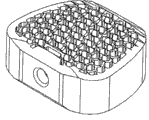
另一类开口优选设计成圆形或椭圆形,并且垂直于通道纵轴延伸。通道纵轴是沿脊骨的纵轴延伸。用例如激光,在植入物中切割出这些开口,并在相对表面的方向上贯穿植入物的外壁,由此将此线上的通道彼此连接起来。为了确保上述稳定性,开口或连接通道也可以在椎笼的内部结束,而不穿透相对的外护套。因此,优选这些连接通道穿过外护套,并在相对外护套的内表面的前面结束。然而,优选开口或缺口沿通道中心轴延伸,并且沿其整个长度以切口或锥形切口形式切割通道壁。这些沿通道壁的纵向切口自然是以这样的方式排列,即相邻通道壁中的数个切口不会切掉整个结构的通道壁的部分。参看图2中的六边形通道和楔形连接通道或缺口,可以将通道壁分为侧壁区域和前-后壁区域。例如,在图2中,只切入侧壁区,以使所有通道壁至少在两个位置与实心外护套连接,而且无一通道壁区段,甚至整个通道结构中数个通道的数个通道壁区域没有一个区段被切掉或拆开。Another type of opening is preferably designed as a circle or an oval and extends perpendicularly to the longitudinal axis of the channel. The channel longitudinal axis extends along the longitudinal axis of the spine. These openings are cut in the implant, eg with a laser, and run through the outer wall of the implant in the direction of the opposite surface, thereby connecting the channels on this line to each other. In order to ensure the aforementioned stability, the openings or connecting channels can also end inside the cage without penetrating the opposite outer sheath. It is therefore preferred that these connecting channels pass through the outer sheath and end in front of the opposite inner surface of the outer sheath. However, it is preferred that the opening or notch extends along the central axis of the channel and cuts the channel wall in the form of a cut or conical cut along its entire length. These longitudinal cuts along the channel walls are naturally arranged in such a way that several cuts in adjacent channel walls do not cut away part of the channel walls of the entire structure. Referring to the hexagonal channel and the wedge-shaped connecting channel or gap in Figure 2, the channel wall can be divided into a side wall area and a front-back wall area. For example, in Figure 2, only the side wall area is cut so that all channel walls are connected to the solid outer sheath at least in two places, and there is no channel wall section, or even several channels of several channels in the entire channel structure No section of the wall area is cut away or disassembled.
开口的直径或厚度在0.1微米到1,000微米的范围内,优选在1微米到500微米的范围内,更优选为10微米到200微米,甚至更优选在30微米到100微米的范围内,并且最优选在50微米到80微米的范围内。The diameter or thickness of the opening is in the range of 0.1 micron to 1,000 micron, preferably in the range of 1 micron to 500 micron, more preferably in the range of 10 micron to 200 micron, even more preferably in the range of 30 micron to 100 micron, and most preferably Preferably in the range of 50 microns to 80 microns.
此外,开口可沿通道纵轴延伸,也就是说,开口是连续的,而且甚至能从一个骨接触面延伸到相对的骨接触面,并由此长度是通道本身的长度。Furthermore, the opening can extend along the longitudinal axis of the channel, that is, the opening is continuous and can even extend from one bone-contacting surface to the opposite bone-contacting surface, and thus the length of the channel itself.
开口还可以呈垂直于通道纵轴穿过植入物的钻孔的形式存在,或作为通道壁中在某些间隔后复现的使通道彼此连接的开口形式存在。The openings can also be present in the form of drilled holes through the implant perpendicular to the longitudinal axis of the channels, or as openings in the channel walls which recur after certain intervals and connect the channels to one another.
通道本身的设计并非本发明的要点,其存在才是。所属领域技术人员很清楚,开口过多会影响植入物的稳定性,因此所属领域技术人员应知道如何根据植入物的类型,来确定开口的数量、尺寸和位置。The design of the channel itself is not the point of the invention, its existence is. Those skilled in the art are well aware that too many openings will affect the stability of the implant, so those skilled in the art should know how to determine the number, size and position of the openings according to the type of the implant.
此外,开口的直径或厚度应小于通道的直径或厚度,而且优选小于通道厚度的十分之一。Furthermore, the diameter or thickness of the opening should be smaller than that of the channel, and preferably less than one-tenth of the thickness of the channel.
大体上,孔可描述为垂直于通道的纵轴,延伸连接通道。本发明的通道结构优选是由实质上平行的通道构成,而所述实质上平行的通道又优选与连接通道平行延伸。In general, holes can be described as extending perpendicular to the longitudinal axis of the channel, connecting the channel. The channel structure according to the invention preferably consists of substantially parallel channels which in turn preferably run parallel to the connecting channels.
当然,并非整个植入物都必须显示本发明的通道结构,而是只有植入物中接触骨或特别是埋入骨中的区域是这样。然而,仍优选本发明的椎间植入物或椎笼的内部通道结构从上覆椎体的下面延伸到下伏椎体的上面。植入物的内部由外护套界定。Of course, not the entire implant has to exhibit the channel structure of the invention, but only the regions of the implant that contact the bone or are in particular embedded in the bone. However, it is still preferred that the internal channel structure of the intervertebral implant or cage of the present invention extend from the underside of the overlying vertebral body to the upper side of the underlying vertebral body. The interior of the implant is bounded by an outer sheath.
具体说来,在椎笼的实施例中,实质上平行的连续通道被证实是有利的,这些通道由沿通道纵轴的楔形纵向缺口连接,如图2、3和4中所示。In particular, in the embodiment of the cage, substantially parallel continuous channels have proven advantageous, these channels being connected by wedge-shaped longitudinal notches along the longitudinal axis of the channels, as shown in FIGS. 2 , 3 and 4 .
此外,优选本发明植入物中的蜂窝状结构(即,内部通道结构)略微高于基本上平坦的骨接触面。尤其是,如果植入物的蜂窝状结构伸到实心边界外,则将提供高表面摩擦和由此带来的良好锚定的优点,同时,由于蜂窝壁(honeycomb wall)的厚度小,故其有可能出现机械移动,这将促进骨的生长刺激。Furthermore, it is preferred that the cellular structure (ie, the inner channel structure) in the implant of the present invention be slightly higher than the substantially planar bone contacting surface. In particular, if the honeycomb structure of the implant protrudes beyond the solid boundary, it will provide the advantages of high surface friction and thus good anchoring, and at the same time, due to the small thickness of the honeycomb wall, its There is a possibility of mechanical movement, which will promote bone growth stimulation.
个别通道之间的壁(即,蜂窝壁或通道壁)的厚度为1微米到3,000微米,优选为5微米到1,000微米,更优选为10微米到500微米,并且特别优选为50微米到250微米。The thickness of the walls between individual channels (i.e., honeycomb or channel walls) is from 1 micron to 3,000 microns, preferably from 5 microns to 1,000 microns, more preferably from 10 microns to 500 microns, and especially preferably from 50 microns to 250 microns .
另外,优选内部通道结构中的开口是以这样的方式排列,即,使整个结构能够微移动(micro-movement),优选为摩擦移动(friction-movement)。例如,对于图2中所示的结构,此类移动是可能的,其中单个通道由侧壁区域中沿通道纵轴的楔形纵向切口连接。由此,个别通道壁可根据楔形开口的厚度,而相对于彼此移位,以致可能发生微移动。In addition, it is preferred that the openings in the internal channel structure are arranged in such a way as to enable micro-movement, preferably friction-movement, of the whole structure. Such a movement is possible, for example, for the structure shown in Figure 2, in which the individual channels are connected by wedge-shaped longitudinal cuts in the region of the side walls along the channel's longitudinal axis. Thereby, the individual channel walls can be displaced relative to each other depending on the thickness of the wedge-shaped opening, so that micro-movements are possible.
如果将此类在通道之间具有开口的构造与所述构造组合,其中内部通道型结构如同小岛一般高出基本上平坦的骨接触区域数毫米,即,所述内部通道型结构是设计成在接触椎体的方向上凸起,则蜂窝状结构的此10毫米凸出部分将刺激骨特别好地生长,因为此升高部分略微刺入骨中,并经由其特性允许微移动,其可随骨移动,而且还通过轻微但连续的刺激促进骨生长。If such a configuration with openings between the channels is combined with the configuration in which the internal channel-type structure is like an island a few millimeters above the substantially flat bone-contacting area, i.e. the internal channel-type structure is designed to Raised in the direction of contact with the vertebral body, this 10mm protrusion of the honeycomb structure will stimulate the bone to grow particularly well, because this raised part penetrates slightly into the bone and by its nature allows micro-movements, which can Moves with bone, but also promotes bone growth with slight but continuous stimulation.
具有刺激骨生长的表面的植入物仍是研究的主题,但尚未得到令人满意的结果。先前描述的能够允许微移动,尤其微摩擦移动的凸出的蜂窝状结构,看起来正是长久以来所寻求的以最佳方式刺激骨生长,并使骨穿过整个植入物快速生长的解决方案。Implants with surfaces that stimulate bone growth are still the subject of research, but satisfactory results have not yet been obtained. The previously described protruding honeycomb structure that allows micro-movements, especially micro-frictional movements, appears to be the long-sought solution to optimally stimulate bone growth and allow rapid growth of bone throughout the implant. plan.
已意外地显示,本发明骨接触、骨连接或骨桥接植入物的通道结构对于骨组织向内生长极为有益,并且提供与所接触的骨的坚固附着。It has surprisingly been shown that the channel structure of the bone-contacting, bone-connecting or bone-bridging implants of the present invention is extremely beneficial for bone tissue ingrowth and provides a strong attachment to the contacted bone.
此外,本发明的蜂窝状结构组合了良好机械稳定性,同时保持最佳填充体积的特征,由此骨能穿过植入物快速而稳定地生长。Furthermore, the honeycomb structure of the present invention combines good mechanical stability while maintaining the characteristics of an optimal filling volume, whereby bone can grow rapidly and stably through the implant.
骨组织一般包括三种细胞类型:成骨细胞、骨细胞和破骨细胞,借此发育的骨还具有由骨衬细胞(bone lining cell)构成的骨顶层。血液的存在是基本的,而且是最佳骨形成所需的。在骨形成期间,成骨细胞、骨细胞和破骨细胞一起作用。成骨细胞是产生骨的细胞,并且负责建造和维持骨。骨表面上无活性的成骨细胞称为骨衬细胞。骨细胞是通过骨化并入骨组织中的前成骨细胞。它们通过将骨吸收调节成骨形成,来保存骨。破骨细胞负责降解骨。经由破骨细胞,可测定骨的厚度,并且可从骨中释放出来钙和磷酸盐。成骨细胞是负责骨形成的细胞。它们是由未分化的间叶细胞(胚胎性结缔组织细胞)发育而成。它们本身如同皮肤层(dermal layer)一般附着于骨,并且尤其通过在胞间隙中分泌磷酸钙和碳酸钙,而间接形成新骨物质的基础,即骨基质。在此过程中,成骨细胞变为骨细胞的骨架,不再能够分裂,并且缓慢矿化,并填充钙。Bone tissue generally includes three cell types: osteoblasts, osteocytes, and osteoclasts, whereby the bone that develops also has a top layer of bone composed of bone lining cells. The presence of blood is essential and required for optimal bone formation. During bone formation, osteoblasts, osteocytes, and osteoclasts work together. Osteoblasts are bone-producing cells and are responsible for building and maintaining bone. The inactive osteoblasts on the bone surface are called bone lining cells. Osteocytes are preosteoblasts incorporated into bone tissue by ossification. They preserve bone by regulating bone resorption into bone formation. Osteoclasts are responsible for degrading bone. Via osteoclasts, bone thickness can be measured and calcium and phosphate can be released from the bone. Osteoblasts are the cells responsible for bone formation. They develop from undifferentiated mesenchymal cells (cells of embryonic connective tissue). They attach themselves to the bone like a dermal layer and indirectly form the basis of new bone substance, the bone matrix, inter alia by secreting calcium phosphate and calcium carbonate in the interstitial space. During this process, osteoblasts become a skeleton of bone cells, no longer able to divide, and slowly mineralize and fill with calcium.
本发明的通道结构看似促进血液内流,并因此促进成骨细胞内流,成骨细胞迅速填充通道间隙,而且与常规植入物所能达到的结果相比,使骨与植入物明显更好地生长在一起。The channel structure of the present invention appears to promote the influx of blood, and thus osteoblasts, which rapidly fill the channel gaps and result in a clearer bone and implant than can be achieved with conventional implants. Better grow together.
此外,本发明设计的植入物相比于例如多孔结构和海绵状物的优势在于,其不太容易变形并且尺寸稳定,具有指定形状和表面,而且能够通过常规植入工具处理,并能够在不致损坏或破坏植入物或植入物中的通道样结构的情况下植入。Furthermore, the inventively designed implant has the advantage over, for example, porous structures and sponges, that it is less deformable and dimensionally stable, has a defined shape and surface, and can be handled by conventional implant tools and can be implanted without damaging or destroying the implant or channel-like structures in the implant.
为了能更好地促进骨细胞附着,可例如通过任何机械、化学或物理粗化,来构筑通道的内表面。为了抑制细菌或其它微生物在植入物表面生长,可为表面配置抗生素,而且外护套的外表面例如可配置药物洗脱涂层(drug eluting coating),所述药物洗脱涂层中储存有例如抗生素等药剂并且能连续释放药剂。In order to better promote bone cell attachment, the inner surface of the channel can be structured, for example by any mechanical, chemical or physical roughening. In order to inhibit the growth of bacteria or other microorganisms on the surface of the implant, antibiotics can be configured on the surface, and the outer surface of the outer sheath, for example, can be configured with a drug eluting coating (drug eluting coating), which stores Agents such as antibiotics and can release the agent continuously.
骨接触植入物Bone Contact Implants
本发明还涉及具有内部通道型结构的可植入骨的(bone implantable)骨连接或骨桥接植入物。The present invention also relates to bone implantable osteosynthetic or bone bridging implants having an internal channel type structure.
在任一类骨连接或骨桥接植入物中大体上都需要骨穿过植入物生长,这是因为生长穿过整个植入物,例如骨螺钉或矫正楔(corrective wedge),或因为生长主要穿过植入物的锚定区域,例如关节植入物或人工椎间盘的锚定销(anchorpin)。Bone growth through the implant is generally required in any type of osteosynthetic or bone-bridging implant, either because the growth traverses the entire implant, such as a bone screw or a corrective wedge, or because the growth primarily An anchor pin passing through an implant, such as a joint implant or an artificial disc.
很明显,实心植入物(例如实心矫正楔)的缺点在于,骨不可能穿过植入物生长,即,植入物必须持久呈现支撑功能,而且植入物的锚定只能在其外表面发生,不存在生长到植入物中而带来更佳固定的骨生长。因此,本发明特别针对至少部分可插入或可植入的骨植入物,其在插入或植入骨中的区域展现本发明的通道型或蜂窝型结构。如果植入物单纯用作隔离物,则进一步存在植入物下陷到骨中而且不再保证所需距离的风险。如果使骨穿过植入物自然生长,则例如可以避免所述缺点。除此之外,本发明的通道型或蜂窝型结构使得在植入期间利用骨代用品或者相似骨片或骨材料积累变得不必要。Obviously, the disadvantage of solid implants (eg solid corrective wedges) is that it is not possible for bone to grow through the implant, i.e. the implant has to permanently assume a supporting function and the implant can only be anchored outside Superficially, there is no bone growth that grows into the implant for better fixation. The present invention is therefore particularly directed to an at least partially insertable or implantable bone implant, which exhibits the inventive channel-type or honeycomb-type structure in the region of insertion or implantation into the bone. If the implant is used purely as a spacer, there is a further risk that the implant sinks into the bone and no longer guarantees the required distance. This disadvantage can be avoided, for example, if the bone is allowed to grow naturally through the implant. In addition, the channel-type or honeycomb-type structure of the present invention makes it unnecessary to utilize bone substitutes or similar bone fragments or accumulation of bone material during implantation.
因此,优选可应用于骨的(bone applicable)骨连接或骨桥接植入物,其提供足够机械稳定性,并且还能使内源骨尽可能完全地生长穿过。Therefore, bone applicable (bone applicable) bone joining or bone bridging implants are preferred, which provide sufficient mechanical stability and also allow endogenous bone to grow through as completely as possible.
此类植入物描述于图11到图19中。Such implants are depicted in FIGS. 11 to 19 .
本发明涉及可应用于骨的骨连接或骨桥接植入物,借此所述植入物具有至少一个骨接触面,以及包括多个具有指定横截面积或半径的通道的内部结构,并且通道经由开口彼此连接,以致产生具有指定半径的三维通道网络,其还允许微移动。The present invention relates to bone-connecting or bone-bridging implants applicable to bone, whereby the implant has at least one bone-contacting surface, and an internal structure comprising a plurality of channels with a specified cross-sectional area or radius, and the channels are connected to each other via openings so that a three-dimensional channel network with a specified radius is created, which also allows micro-movements.
意外地发现,当可应用于骨的骨连接或骨桥接植入物的表面不光滑,或不粗糙,或不是多孔,但具有通道结构时,所述植入物与所接触的骨特别好地生长在一起,其中通道经由开口彼此连接,并且具有指定结构。通道结构的性质和对称性是本发明的要点,并且将于下文详细描述。Surprisingly, it has been found that osteosynthetic or bone bridging implants applicable to bone have a particularly good contact with the bone when the surface of the implant is not smooth, or rough, or porous, but has a channel structure. grow together, where the channels are connected to each other via openings, and have a defined structure. The nature and symmetry of the channel structure is central to the invention and will be described in detail below.
术语“骨接触”或“骨连接”或“骨桥接”应理解为,植入物与骨直接接触,即,植入物的至少一部分表面与骨接触。The term "bone-contacting" or "bone-connecting" or "bone-bridging" is understood to mean that the implant is in direct contact with the bone, ie that at least a part of the implant's surface is in contact with the bone.
此类植入物的实例有:脊骨植入物、髋关节植入物、肩关节植入物、手指关节植入物、踝关节植入物、脚趾关节植入物、膝关节植入物、踝关节植入物、腕关节植入物或全身关节植入物、用于骨融合的植入物、夹头(radius head)植入物、内置假体、植入物或用于植入物的锚定销、牙科植入物、颅骨植入物、矫正楔、角度植入物(angle implant)、用于成角(胫骨)的植入物、跖骨手术、连接后肢手术(connect rear foot surgery)或者一般来说,连接骨或至少部分在骨中实施的植入物。大体上,在骨中作为部件使用的任何植入物都能装备本发明的通道型或蜂窝型结构。Examples of such implants are: spine implants, hip implants, shoulder implants, finger joint implants, ankle implants, toe joint implants, knee implants , ankle implants, wrist implants or whole body joint implants, implants for bone fusion, radius head implants, endoprostheses, implants or implants for anchor pins for implants, dental implants, cranial implants, corrective wedges, angle implants, implants for angulation (tibia), metatarsal surgery, connect rear foot surgery surgery) or in general, an implant that connects or is at least partially implemented in bone. In general, any implant used as a component in bone can be equipped with the channel or honeycomb structure of the present invention.
本发明植入物可通过标准技术,例如使用激光技术和激光切割程序、激光融合(例如Lasercusing技术)制造,并由此可在所述本发明情形中呈现任何形状。Implants of the invention can be produced by standard techniques, eg using laser technology and laser cutting procedures, laser fusion (eg Lasercusing techniques), and thus can assume any shape in the context of the invention described.
具体说来,在髋关节植入物中,髋关节植入物的轴根据本发明设计。在膝关节植入物中,股骨组件和胫骨组件,特别是其锚定销,可配备本发明的通道结构。具体说来,欲用于骨中的锚定销配置本发明的结构。特别是应用于颈椎、胸椎、腰椎的椎笼(例如ALIF椎笼、PLIF椎笼和TLIF椎笼)以及人工椎间盘都可列出作为脊骨植入物。In particular, in hip implants, the shaft of the hip implant is designed according to the invention. In knee implants, the femoral and tibial components, in particular their anchor pins, can be equipped with the channel structure of the invention. In particular, the anchor pin intended for use in bone configures the structure of the invention. In particular, cages for cervical, thoracic, and lumbar applications (such as ALIF cages, PLIF cages, and TLIF cages) and artificial intervertebral discs are listed as spinal implants.
上述植入物通常是由硬材料,尤其例如钛、外科不锈钢、钴铬钢、钽等金属或金属合金制成,但也可以由纤维增强塑料(具有相应基质的玻璃纤维/碳纤维)、聚(醚醚酮)[PEEK],或总的来说聚合物材料制成。The aforementioned implants are usually made of hard materials, especially metals or metal alloys such as titanium, surgical stainless steel, cobalt chromium steel, tantalum, etc., but can also be made of fiber reinforced plastics (glass fibers/carbon fibers with corresponding matrix), poly( Ether ether ketone) [PEEK], or polymeric materials in general.
为此,本发明的通道结构不是在多件式植入物(例如椎间植入物,例如人工椎间盘或膝关节植入物)的接合表面(articulating surface)区中。For this reason, the channel structure of the present invention is not in the region of the articulating surface of a multi-piece implant, such as an intervertebral implant, such as an artificial intervertebral disc or a knee joint implant.
整体式植入物(例如椎笼)通常具有无通道结构的实心外护套,以便确保植入物具有足够稳定性。One-piece implants such as vertebral cages usually have a solid outer sheath with no channel structure in order to ensure sufficient stability of the implant.
多件式植入物中的术语“接合表面”应理解为一个植入物部件中可与另一植入物部件表面接触的表面。另一方面,接触面可理解为在特定状态或时刻,两个植入物部件的表面实际接触的区域。The term "engagement surface" in multi-piece implants is to be understood as a surface of one implant component which can come into contact with a surface of another implant component. On the other hand, a contact surface is to be understood as the area where the surfaces of two implant components are actually in contact at a certain state or moment.
本发明的通道结构是在植入物的骨接触面起始,以致通道的开口面向骨。The channel structure of the present invention is initiated at the bone-contacting surface of the implant such that the opening of the channel faces the bone.
在脊骨区域的骨连接或骨桥接植入物中,植入物与各自骨的接触面是平坦的,并且通道沿脊骨的纵轴延伸,而远离所述骨接触区域。In bone-connecting or bone-bridging implants in the region of the spine, the contact surfaces of the implant with the respective bone are planar and the channel extends along the longitudinal axis of the spine away from said bone-contacting region.
然而,与骨接触的表面不是必须设计成平坦的,而是也可以具有不对称形状,例如髋关节股骨柄(hip stem)的股骨柄、膝关节植入物的股骨组件;或可以是圆形的,如膝关节植入物中胫骨组件的骨柄、髋关节植入物的髋臼,或角度植入物,其用于重新调节性截骨术(readjustment osteotomy)中。此外,与骨接触的表面可以是锯齿形、细齿形、凸起的,或具有倒钩以在植入后,接着使骨穿过植入物生长,还能立即很好地扣紧。However, the bone-contacting surface does not have to be designed to be flat, but can also have an asymmetrical shape, such as the femoral stem of a hip stem, the femoral component of a knee implant; or can be rounded , such as the stem of the tibial component in knee implants, the acetabulum of hip implants, or angled implants used in readjustment osteotomy. In addition, the bone contacting surface may be serrated, serrated, raised, or barbed to fasten well immediately after implantation followed by bone growth through the implant.
因此,通道是在植入物的骨接触面开始。本发明的要点在于,个别通道,或所有通道中至少75%,优选所有通道中至少85%,并且特别优选所有通道中至少95%的横截面积为8,000平方微米到7,000,000平方微米,优选50,000平方微米到3,100,000平方微米,更优选在100,000平方微米到800,000平方微米范围内,甚至更优选在125,000平方微米到650,000平方微米范围内,并且特别优选在160,000平方微米到570,000平方微米范围内。Thus, the channel begins at the bone-contacting surface of the implant. The gist of the invention is that individual channels, or at least 75% of all channels, preferably at least 85% of all channels, and particularly preferably at least 95% of all channels, have a cross-sectional area of 8,000 square microns to 7,000,000 square microns, preferably 50,000 square microns microns to 3,100,000 square microns, more preferably in the range of 100,000 square microns to 800,000 square microns, even more preferably in the range of 125,000 square microns to 650,000 square microns, and particularly preferably in the range of 160,000 square microns to 570,000 square microns.
所有通道中有85%的横截面积在上述面积范围内的表述意味着,在100个通道中,有85个通道的横截面积在上述范围内,而其余15个通道可具有较小或较大,以及明显较小或明显较大的横截面积。The statement that 85% of the cross-sectional areas of all channels are within the above range means that out of 100 channels, 85 channels have a cross-sectional area within the above range, while the remaining 15 channels may have smaller or larger cross-sectional areas. Large, and significantly smaller or significantly larger cross-sectional areas.
通道可具有任何所需形状,并且必要时,其可以设计成圆形、椭圆形、三角形、正方形、五边形、六边形、七边形、八边形或多边形。但是,优选内角大于90°的实施例,从五边形开始到多边形,乃至圆形或椭圆形。还优选五边形、六边形、七边形和八边形的实施例,而且特别优选六边形通道。The channels can have any desired shape and, if necessary, they can be designed as circular, elliptical, triangular, square, pentagonal, hexagonal, heptagonal, octagonal or polygonal. However, embodiments with interior angles greater than 90° are preferred, starting from pentagons to polygons and even circles or ellipses. Preference is also given to pentagonal, hexagonal, heptagonal and octagonal embodiments, and particular preference is given to hexagonal channels.
对于圆形通道,横截面积等于圆面积,而且易于根据πr2计算,其中r是通道的半径。For circular channels, the cross-sectional area is equal to the area of the circle and is easily calculated from πr2 , where r is the radius of the channel.
就圆形或近似圆形的通道形式来说,优选各通道或者所有通道中至少75%,优选所有通道中至少85%,并且特别优选所有通道中至少95%的直径为100微米到3,000微米,优选为250微米到2,000微米,更优选为350微米到1,000微米,甚至更优选为400微米到900微米,并且最优选为450微米到850微米。In the case of circular or approximately circular channel forms, preferably at least 75% of each channel or all channels, preferably at least 85% of all channels, and particularly preferably at least 95% of all channels have a diameter of 100 μm to 3,000 μm, Preferably it is 250 microns to 2,000 microns, more preferably 350 microns to 1,000 microns, even more preferably 400 microns to 900 microns, and most preferably 450 microns to 850 microns.
在多边形通道形状中,对于具有偶数边的多边形(正方形、六边形、八边形等),直径是指两个相对的平行表面之间的距离,或对于具有奇数边的多边形(三角形、五边形、七边形等),直径是指隅角点到相对表面的中心的距离。In polygonal channel shapes, diameter is the distance between two opposing parallel surfaces for polygons with even sides (square, hexagon, octagon, etc.), or for polygons with odd sides (triangle, pentagon, etc.) polygon, heptagon, etc.), the diameter is the distance from the corner point to the center of the opposing surface.
通道壁的厚度为20微米到700微米,优选为30微米到550微米,并且更优选为40微米到400微米。通道直径优选是通道壁厚度的2倍到4倍。外护套的厚度为500微米到1,500微米,优选为700微米到1,300微米,并且最优选为850微米到1,100微米。外护套的厚度优选对应于通道直径的1倍到2倍。切口或连接通道的厚度或开口直径优选是通道厚度的三分之一到十分之一。The thickness of the channel walls is from 20 microns to 700 microns, preferably from 30 microns to 550 microns, and more preferably from 40 microns to 400 microns. The channel diameter is preferably 2 to 4 times the channel wall thickness. The thickness of the outer sheath is from 500 microns to 1,500 microns, preferably from 700 microns to 1,300 microns, and most preferably from 850 microns to 1,100 microns. The thickness of the outer sheath preferably corresponds to 1 to 2 times the channel diameter. The thickness or opening diameter of the cutout or connecting channel is preferably one third to one tenth of the channel thickness.
具有上述直径或上述横截面积的通道从附着于骨的植入物表面延伸到植入物内部。具有相对骨接触面的优选的本发明整体式植入物(例如椎笼或骨楔)的通道优选延伸穿过植入物,到达相对的骨接触面。A channel having the above-mentioned diameter or the above-mentioned cross-sectional area extends from the surface of the implant attached to the bone to the interior of the implant. The channels of preferred one-piece implants of the present invention having opposing bone-contacting surfaces (eg, vertebral cages or bone wedges) preferably extend through the implant to the opposing bone-contacting surfaces.
在具有接合表面的植入物中,通道优选不是在接合表面结束,而只是完全穿过植入物,其中横过骨接触面的通道开口是结束于植入物的非接合区。In implants with an articulation surface, the channel preferably does not end at the articulation surface, but only passes completely through the implant, wherein the opening of the channel across the bone-contacting surface ends at the non-engaging area of the implant.
但是,如果通道是朝向接合表面延伸,则优选通道不是在接合表面上结束,而是优选在植入物中部结束,以致不影响植入物的机械稳定性。However, if the channel extends towards the articulation surface, it is preferred that the channel does not end on the articulation surface, but preferably in the middle of the implant, so as not to affect the mechanical stability of the implant.
具有上述直径或上述横截面积的通道从附着于骨的植入物表面延伸到植入物内部。具有相对骨接触面的本发明的优选整体式植入物(例如本发明的椎笼)的通道优选延伸穿过植入物,到达相对的骨接触面。A channel having the above-mentioned diameter or the above-mentioned cross-sectional area extends from the surface of the implant attached to the bone to the interior of the implant. The channel of a preferred one-piece implant of the invention having an opposing bone-contacting surface (eg, a vertebral cage of the invention) preferably extends through the implant to the opposing bone-contacting surface.
本发明植入物的通道优选不是在外护套的高度处结束,而是超出其高度最多10毫米。The channel of the implant according to the invention preferably does not end at the level of the outer sheath, but exceeds its height by a maximum of 10 mm.
通道的设计是本发明的要点,而且本发明的通道网络遵循对称性。应注意,随机发生的通道网络,例如多孔结构或海绵状物中存在的不对称通道网络,不能解决本发明的问题。无规律地改变方向和直径,和/或随机序列和/或形状是由多层系统偶然产生的通道,也不能解决本发明的问题。在所述系统中,血流只是在一些区域中增加,而且只能在某些区域或时刻看到骨细胞形成,骨细胞穿过整个植入物的生长减缓,或只能部分发生。The design of the channels is the gist of the invention, and the channel network of the invention follows symmetry. It should be noted that randomly occurring channel networks, such as asymmetric channel networks present in porous structures or sponges, do not solve the problem of the present invention. Irregularly changing directions and diameters, and/or random sequences and/or shapes of channels that are produced by chance by the multilayer system, also do not solve the problem of the present invention. In such systems, blood flow is only increased in some areas, and bone cell formation is only seen in certain areas or times, and growth of bone cells across the entire implant is slowed, or only partially occurs.
根据本发明,通道实质上彼此平行,并且呈直线,即,通道无转弯、弯曲、曲线等,而是从其在植入物外表面上的开口实质上平行延伸到植入物或一部分植入物中,并在植入物内部结束,或优选贯穿植入物,到达植入物的相对外表面。此外,不管通道是圆形、椭圆形还是多边形通道,其优选不会连续,也不会突然或逐渐改变其半径或直径。According to the invention, the channels are substantially parallel to each other and straight, i.e. the channels have no turns, bends, curves, etc., but extend substantially parallel from their openings on the outer surface of the implant to the implant or part of the implant. within the implant and end within the implant, or preferably throughout the implant, to the opposite outer surface of the implant. Furthermore, whether a channel is circular, elliptical or polygonal, it preferably is not continuous, nor does it change its radius or diameter abruptly or gradually.
术语“实质上平行”应理解为,存在某些制造公差,而除这些公差外,通道彼此平行。The term "substantially parallel" is understood to mean that, apart from certain manufacturing tolerances, the channels are parallel to each other.
所有通道也并非必须彼此平行。例如,也有可能植入物具有两个插入骨中的锚定销,而这两个锚定销彼此不平行。两个锚定销可具有本发明的通道结构,其中一个锚定销中的通道实质上相互平行,而且另一锚定销的通道也如此,但第一锚定销中的通道与第二锚定销中的通道不平行。It is also not necessary that all channels are parallel to each other. For example, it is also possible that the implant has two anchoring pins inserted into the bone which are not parallel to each other. Two anchor pins may have the channel structure of the present invention, wherein the channels in one anchor pin are substantially parallel to each other, and so are the channels in the other anchor pin, but the channels in the first anchor pin are parallel to the second anchor pin. The channels in the dowel are not parallel.
因此,本文中提及通道组,借此一组通道实质上彼此平行,但并非必须所述通道组都彼此平行。Thus, reference is made herein to a set of channels whereby a set of channels are substantially parallel to each other, although it is not necessary that the sets of channels are all parallel to each other.
另外,通道直径在其路线中不会改变,即,同样,除制造公差外,通道的开始到结束具有基本上相同的直径。In addition, the channel diameter does not change during its course, ie, again, apart from manufacturing tolerances, the channel has substantially the same diameter from start to finish.
所有通道也并非必须都从骨接触面起始,即,与骨直接接触。所有通道中最多30%,优选最多20%也可以在植入物中不直接接触骨的一个区域开始,即,这些通道优选从骨接触面侧面开始。It is also not necessary for all channels to originate from a bone-contacting surface, ie, in direct contact with the bone. Up to 30%, preferably up to 20%, of all channels can also start in an area of the implant that does not directly contact the bone, ie the channels preferably start laterally from the bone-contacting surface.
另一方面,通道也不需要都在骨接触面结束,总之,这可能只是利用整体式骨连接或骨桥接植入物的情形。高达100%的所有通道也可以在不接触骨的表面结束,但也有可能高达100%的通道在相对的骨接触面结束,而这是制造本发明的整体式椎笼所优选的。On the other hand, the channels need not all end at the bone-contacting surface, anyway, this may only be the case with integral bone-connecting or bone-bridging implants. Up to 100% of all channels may also end on the non-bone-contacting surface, but it is also possible that up to 100% of the channels end on the opposite bone-contacting surface, which is preferred for making the monolithic cage of the present invention.
此外,优选除本发明植入物的实心外护套外,每平方厘米骨接触面起始至少50个通道,优选至少100个通道,更优选至少150个通道。本发明的通道结构每平方厘米包括20到1,000个通道,优选50到750个通道,更优选100到500个通道,再更优选125到350个通道,并且特别优选每平方厘米包括介于150与250个之间的通道。Furthermore, preferably at least 50 channels, preferably at least 100 channels, more preferably at least 150 channels are initiated per square centimeter of bone contacting surface in addition to the solid outer sheath of the implant of the invention. The channel structure of the present invention comprises 20 to 1,000 channels per square centimeter, preferably 50 to 750 channels, more preferably 100 to 500 channels, still more preferably 125 to 350 channels, and particularly preferably comprises between 150 and 1,000 channels per square centimeter. 250 channels between.
此外,使通道互连也是本发明的要点。通道经由开口彼此连接,其中各通道具有至少一个开口通往一个相邻通道。还优选外部通道,即,形成整个通道型结构的外部行并且紧靠实心外护套的那些通道,具有至少一个开口通往一个相邻通道,而位于所述通道型结构内部的通道具有至少一个开口通往两个相邻通道,即,实际包括至少两个开口。Furthermore, interconnecting the channels is also a gist of the invention. The channels are connected to each other via openings, wherein each channel has at least one opening leading to an adjacent channel. It is also preferred that the outer channels, i.e. those channels forming the outer row of the overall channel-type structure and abutting the solid outer sheath, have at least one opening to an adjacent channel, while the channels located inside said channel-type structure have at least one An opening leads to two adjacent channels, ie actually comprises at least two openings.
此外,优选以使所有通道彼此连接的方式排列所述开口,即,理论上可利用例如血液等液体经由一个通道的一个开口填充整个通道型结构。因此,优选建立整个结构的三维互连。Furthermore, the openings are preferably arranged in such a way that all channels are connected to each other, ie the entire channel-type structure can theoretically be filled with a liquid such as blood via one opening of one channel. Therefore, it is preferable to establish a three-dimensional interconnection of the entire structure.
必要时,开口或所谓的连接通道可设计成孔或切口形式,而且可能是圆形、圆环形、点状、圆柱形、椭圆形、正方形、楔形或具有任何其它构造。The openings or so-called connecting channels can be designed in the form of holes or cutouts, if necessary, and can be circular, annular, point-shaped, cylindrical, oval, square, wedge-shaped or have any other configuration.
还优选通道之间的开口遵循一种模式,即,对称或复现次序。因此,优选通道之间的开口沿通道的纵轴延伸,而且开口可具有对应于互连通道长度的最大长度。所述沿通道纵轴延伸的开口类型优选为通道壁或通道覆层中的切口,优选楔形切口。It is also preferred that the openings between channels follow a pattern, ie a symmetrical or recurring sequence. Thus, preferably the openings between the channels extend along the longitudinal axis of the channels, and the openings may have a maximum length corresponding to the length of the interconnecting channels. The type of opening extending along the longitudinal axis of the channel is preferably a cutout, preferably a wedge-shaped cutout, in the channel wall or in the channel coating.
还优选通道之间的开口遵循一种模式,即,对称或复现次序。因此,优选通道之间的开口沿通道的长轴延伸,而且开口可具有对应于互连通道长度的最大长度。所述沿通道长轴延伸的开口类型优选为通道壁或通道杆中的切口,优选楔形切口。It is also preferred that the openings between channels follow a pattern, ie a symmetrical or recurring sequence. Thus, preferably the openings between channels extend along the long axis of the channels, and the openings may have a maximum length corresponding to the length of the interconnecting channels. The type of opening extending along the long axis of the channel is preferably a cutout, preferably a wedge-shaped cutout, in the channel wall or in the channel rod.
另一类开口优选设计成圆形或椭圆形,并且垂直于通道纵轴延伸。通道纵轴是沿脊骨的长轴延伸。用例如激光,在植入物中切割出这些开口,并在相对表面的方向上贯穿植入物的外壁,由此将这条线上的通道彼此连接起来。为了确保上述稳定性,开口或连接通道也可以在椎笼的内部结束,而不穿透相对的外护套。因此,优选这些连接通道穿过外护套,并在相对外护套的内表面的前面结束。然而,优选开口或缺口沿通道中心轴延伸,并且沿其整个长度以切口或锥形切口形式切割通道壁。这些沿通道壁的纵向切口通常是这样的方式排列,即相邻通道壁中的数个切口不会切掉整个结构的通道壁的部分。参看图2中的六边形通道和楔形连接通道或缺口,可以将通道壁分为侧壁区域和前-后壁区域。例如,在图2中,只切入侧壁区,以使所有通道壁至少在两个位置与实心外护套连接,而且无一通道壁区段,甚至整个通道结构中数个通道的数个通道壁区域没有一个区段被切掉或拆开。Another type of opening is preferably designed as a circle or an oval and extends perpendicularly to the longitudinal axis of the channel. The channel longitudinal axis extends along the long axis of the spine. These openings are cut in the implant, eg with a laser, and run through the outer wall of the implant in the direction of the opposite surface, thereby connecting the channels on this line to one another. In order to ensure the aforementioned stability, the openings or connecting channels can also end inside the cage without penetrating the opposite outer sheath. It is therefore preferred that these connecting channels pass through the outer sheath and end in front of the opposite inner surface of the outer sheath. However, it is preferred that the opening or notch extends along the central axis of the channel and cuts the channel wall in the form of a cut or conical cut along its entire length. These longitudinal cuts along the channel walls are usually arranged in such a way that several cuts in adjacent channel walls do not cut away part of the channel walls of the entire structure. Referring to the hexagonal channel and the wedge-shaped connecting channel or gap in Figure 2, the channel wall can be divided into a side wall area and a front-back wall area. For example, in Figure 2, only the side wall area is cut so that all channel walls are connected to the solid outer sheath at least in two places, and there is no channel wall section, or even several channels of several channels in the entire channel structure No section of the wall area is cut away or disassembled.
开口的直径或厚度在0.1微米到1,000微米的范围内,优选在2微米到600微米的范围内,更优选为15微米到300微米,甚至更优选在25微米到120微米的范围内,并且最优选在40微米到90微米的范围内。The openings have a diameter or thickness in the range of 0.1 microns to 1,000 microns, preferably in the range of 2 microns to 600 microns, more preferably in the range of 15 microns to 300 microns, even more preferably in the range of 25 microns to 120 microns, and most preferably Preferably in the range of 40 microns to 90 microns.
此外,开口可沿通道纵轴延伸,也就是说,开口是连续的,而且甚至能从一个骨接触面延伸到相对的骨接触面,并由此长度是通道本身的长度。Furthermore, the opening can extend along the longitudinal axis of the channel, that is, the opening is continuous and can even extend from one bone-contacting surface to the opposite bone-contacting surface, and thus the length of the channel itself.
开口还可以呈垂直于通道纵轴穿过植入物的钻孔的形式存在,或作为通道壁中在某些间隔后复现的使通道彼此连接的开口形式存在。The openings can also be present in the form of drilled holes through the implant perpendicular to the longitudinal axis of the channels, or as openings in the channel walls which recur after certain intervals and connect the channels to one another.
通道本身的设计并非本发明的要点,其存在才是。所属领域技术人员很清楚,开口过多会影响植入物的稳定性,因此所属领域技术人员应知道如何根据植入物的类型,来确定开口的数量、尺寸和位置。The design of the channel itself is not the point of the invention, its existence is. Those skilled in the art are well aware that too many openings will affect the stability of the implant, so those skilled in the art should know how to determine the number, size and position of the openings according to the type of the implant.
此外,开口的直径或厚度应小于通道的直径或厚度,而且优选小于通道厚度的十分之一。Furthermore, the diameter or thickness of the opening should be smaller than that of the channel, and preferably less than one-tenth of the thickness of the channel.
对于不连续并且在植入物内部结束的通道,例如在接合表面上结束的通道,连接通道的开口位于植入物中通道结束的区域更为有利。For channels that are discontinuous and end inside the implant, eg on the joint surface, it is advantageous for the opening of the connecting channel to be located in the region of the implant where the channel ends.
大体上,孔可描述为垂直于通道的纵轴,延伸连接通道。本发明的通道结构优选是由实质上平行的通道构成,而所述实质上平行的通道又优选与连接通道平行延伸。In general, holes can be described as extending perpendicular to the longitudinal axis of the channel, connecting the channel. The channel structure according to the invention preferably consists of substantially parallel channels which in turn preferably run parallel to the connecting channels.
当然,并非整个植入物都必须显示本发明的通道结构,而是只有植入物中接触骨或特别是埋入骨中的区域是这样。然而,还优选本发明的椎间植入物或椎笼的内部通道结构从上覆椎体的下面延伸到下伏椎体的上面。植入物的内部由外护套界定。Of course, not the entire implant has to exhibit the channel structure of the invention, but only the regions of the implant that contact the bone or are in particular embedded in the bone. However, it is also preferred that the internal channel structure of the intervertebral implant or cage of the present invention extends from below the overlying vertebral body to above the underlying vertebral body. The interior of the implant is bounded by an outer sheath.
具体说来,在椎笼的实施例中,连续通道实质上平行被证实是有利的,这些通道由沿通道纵轴的楔形纵向缺口连接,如图3、5和6中所示。In particular, in the embodiment of the cage, it has proven advantageous that the successive channels are substantially parallel, the channels being connected by wedge-shaped longitudinal notches along the longitudinal axis of the channels, as shown in FIGS. 3 , 5 and 6 .
此外,优选本发明植入物中的蜂窝状结构(即,内部通道结构)略微高于基本上平坦的骨接触面。尤其是,如果植入物的蜂窝状结构伸到实心边界外,则将提供高表面摩擦和由此带来的良好锚定的优点,同时,由于蜂窝壁的厚度小,故其有可能出现机械移动,这将促进骨的生长刺激。Furthermore, it is preferred that the cellular structure (ie, the inner channel structure) in the implant of the present invention be slightly higher than the substantially planar bone contacting surface. In particular, if the honeycomb structure of the implant protrudes beyond the solid boundaries, it will provide the advantages of high surface friction and thus good anchoring, while at the same time, due to the small thickness of the honeycomb walls, it will have the possibility of mechanical damage. Move, which will promote bone growth stimulation.
个别通道之间的壁(即,蜂窝壁或通道壁)的厚度为1微米到3,000微米,优选为5微米到1,000微米,更优选为10微米到500微米,并且特别优选为50微米到250微米。The thickness of the walls between individual channels (i.e., honeycomb or channel walls) is from 1 micron to 3,000 microns, preferably from 5 microns to 1,000 microns, more preferably from 10 microns to 500 microns, and especially preferably from 50 microns to 250 microns .
另外,优选内部通道结构中的开口是以这样的方式排列,即,使整个结构能够微移动,优选为摩擦移动。例如,对于图2中所示的结构,此类移动是可能的,其中个别通道由侧壁区域中沿通道纵轴的楔形纵向切口连接。由此,个别通道壁可根据楔形开口的厚度,而相对于彼此移位,以致可能发生微移动。In addition, it is preferred that the openings in the internal channel structure are arranged in such a way as to allow micro-movement, preferably frictional movement, of the entire structure. Such a movement is possible, for example, for the structure shown in Figure 2, in which the individual channels are connected by wedge-shaped longitudinal cuts in the side wall regions along the channel's longitudinal axis. Thereby, the individual channel walls can be displaced relative to each other depending on the thickness of the wedge-shaped opening, so that micro-movements are possible.
本发明的要点在于,归因于本发明的通道型或蜂窝型结构,而可能发生微移动。为了刺激骨生长,并由此确保骨能够穿过植入物或植入物引入骨中的部分快速而稳定地生长,除在植入物中提供通道外,还在通道壁中提供切口或凹口也是本发明的要点。通道促进血液流动,并为新的骨细胞附着提供较大表面积,借此通道壁中的凹口或孔或切口形成三维网络,从而使所有通道彼此连接,并且还确保通道壁能够允许微移动。重要的是,凹口或切口使通道壁只能在较窄的范围内移动,而这个范围是由切口或凹口的厚度界定。使用上述楔形切口实例,通道壁只可能在一定范围内移动,例如楔形物的尖端可在切口中移动。从图6中易于发现,楔形切口允许侧向和前-后方向微移动。在楔形切口中,受切口厚度以及横过楔形物的切口的厚度限制,通道壁的楔形侧可例如侧向在楔形切口的内外移动,其次,通道壁的楔形侧可例如前向和后向移动,直到其碰到通道壁的V形壁。The gist of the invention is that micro-movements are possible due to the channel-type or honeycomb-type structure of the invention. In order to stimulate bone growth and thereby ensure rapid and stable bone growth through the implant or the part of the implant introduced into the bone, in addition to providing channels in the implant, incisions or recesses are provided in the walls of the channels Mouth is also the gist of the present invention. The channels promote blood flow and provide a large surface area for new bone cells to attach, whereby the notches or holes or cuts in the channel walls form a three-dimensional network that connects all the channels to each other and also ensures that the channel walls allow micro-movements. Importantly, the notches or notches allow the channel walls to move only within a narrow range, which is defined by the thickness of the notches or notches. Using the wedge cutout example above, movement of the channel walls is only possible to a certain extent, eg the tip of the wedge can move in the cutout. It is easy to see from Fig. 6 that the wedge-shaped cutout allows for slight movement in the lateral and anterior-posterior directions. In a wedge cut, the wedge side of the channel wall can move, for example laterally, inside and outside the wedge cut, limited by the thickness of the cut and the thickness of the cut across the wedge, and secondly, the wedge side of the channel wall can move, for example, forward and backward , until it hits the V-shaped wall of the channel wall.
因此,这些V形或楔形缺口是允许整个通道型结构微移动的本发明的一个可能实施例。便利微移动的另一实现方案是图20和图21中所说明的实施例。图20是上文详细描述的植入物中通道型结构的截面。图21是允许微移动的另一种可能的缺口排列。当然,其它可能性也是可以想得到的,这在所属领域技术人员的技能范围内,只要了解了打算利用这些开口干什么,无需创新性尝试,就能够设计出数种其它相当的设计。Thus, these V-shaped or wedge-shaped notches are a possible embodiment of the present invention that allow micro-movement of the entire channel-like structure. Another implementation to facilitate micro-movement is the embodiment illustrated in FIGS. 20 and 21 . Figure 20 is a cross-section of a channel-type structure in the implant described in detail above. Figure 21 is another possible notch arrangement to allow micro-movement. Of course, other possibilities are also conceivable, and it is within the skill of a person skilled in the art to devise several other equivalent designs without innovative attempts, once one knows what the openings are intended to be used for.
在这些实施例中,切口不是必须对应于通道的长度。沿通道纵向方向的切口的长度可对应于通道长度到1微米、优选5微米并且特别优选10微米长度。In these embodiments, the cutout does not necessarily correspond to the length of the channel. The length of the cuts in the longitudinal direction of the channel may correspond to a channel length of up to 1 micrometer, preferably 5 micrometers and particularly preferably 10 micrometers in length.
凹口厚度以及切口厚度在0.1微米到1,000微米的范围内,优选在1微米到500微米的范围内,更优选为10微米到200微米,甚至更优选在30微米到100微米的范围内,并且最优选在50微米到80微米的范围内。所述厚度是指从切开的通道壁中缺口一侧到另一侧之间的最短距离。在图6中,所给出的厚度为0.06,其对应于所切下的通道壁的距离。The thickness of the notch and the thickness of the cut are in the range of 0.1 micron to 1,000 microns, preferably in the range of 1 micron to 500 microns, more preferably in the range of 10 microns to 200 microns, even more preferably in the range of 30 microns to 100 microns, and Most preferably in the range of 50 microns to 80 microns. The thickness refers to the shortest distance from one side of the notch in the cut channel wall to the other side. In Figure 6, the thickness is given as 0.06, which corresponds to the distance of the channel wall cut away.
切口的长度对应于沿通道纵轴的长度。缺口深度是指通道壁前面到背面的路径。因此,在直线式缺口中,切口深度是通道壁厚度。The length of the cut corresponds to the length along the longitudinal axis of the channel. The notch depth is the path from the front to the back of the channel wall. Thus, in a linear notch, the notch depth is the channel wall thickness.
在倾斜或楔形缺口中,切口深度是通道壁厚度(即,通道壁前面到背面的厚度)的1.02倍到5倍,优选1.1倍到4.0倍,更优选1.3倍到3.0倍,甚至更优选1.4倍到2.5倍,并且最优选1.5倍到2.0倍。In inclined or wedge-shaped notches, the depth of the cut is 1.02 to 5 times, preferably 1.1 to 4.0 times, more preferably 1.3 to 3.0 times, even more preferably 1.4 times the thickness of the channel wall (i.e. times to 2.5 times, and most preferably 1.5 times to 2.0 times.
如果将此类在通道之间具有开口的构造与所述构造组合,其中内部通道型结构如同小岛一般高出基本上平坦的骨接触区域数毫米,即,所述内部通道型结构是设计成在接触椎体的方向上凸起,则蜂窝状结构的此10毫米凸出部分将刺激骨较好地生长,因为此升高部分略微刺入骨中,并经由其特性允许微移动,其可随骨移动,而且还通过轻微但连续的刺激促进骨生长。If such a configuration with openings between the channels is combined with the configuration in which the internal channel-type structure is like an island a few millimeters above the substantially flat bone-contacting area, i.e. the internal channel-type structure is designed to Raised in the direction of contact with the vertebral body, this 10 mm protrusion of the honeycomb structure will stimulate better bone growth, as this raised portion penetrates slightly into the bone and allows micro-movements by its nature, which can Moves with bone, but also promotes bone growth with slight but continuous stimulation.
具有刺激骨生长的表面的植入物仍是研究的主题,但尚未得到令人满意的结果。先前描述的能够允许微移动,尤其微摩擦移动的凸出的蜂窝状结构,看起来正是长久以来所寻求的以最佳方式刺激骨生长,并使骨穿过整个植入物快速生长的解决方案。Implants with surfaces that stimulate bone growth are still the subject of research, but satisfactory results have not yet been obtained. The previously described protruding honeycomb structure that allows micro-movements, especially micro-frictional movements, appears to be the long-sought solution to optimally stimulate bone growth and allow rapid growth of bone throughout the implant. plan.
已意外地显示,本发明骨接触、骨连接或骨桥接植入物的通道结构对于骨组织向内生长极为有益,并且提供与所接触的骨的坚固并合。It has surprisingly been shown that the channel structure of the bone-contacting, bone-connecting or bone-bridging implants of the present invention is extremely beneficial for bone tissue ingrowth and provides a robust fusion with the contacted bone.
此外,本发明的蜂窝状结构组合了良好机械稳定性,同时保持最佳填充体积的特征,以致骨能穿过植入物快速而稳定地生长。Furthermore, the honeycomb structure of the present invention combines good mechanical stability while maintaining the characteristics of an optimal filling volume so that bone can grow rapidly and stably through the implant.
骨组织一般包括三种细胞类型:成骨细胞、骨细胞和破骨细胞,借此发育的骨还具有由骨衬细胞构成的骨顶层。血液的存在是基本的,而且是最佳骨形成所需的。在骨形成期间,成骨细胞、骨细胞和破骨细胞一起作用。成骨细胞是产生骨的细胞,并且负责建造和维持骨。骨表面上无活性的成骨细胞称为骨衬细胞。骨细胞是通过骨化并入骨组织中的前成骨细胞。它们通过将骨吸收调节成骨形成,来保存骨。破骨细胞负责降解骨。经由破骨细胞,可测定骨的厚度,并且可从骨中释放出来钙和磷酸盐。成骨细胞是负责骨形成的细胞。它们是由未分化的间叶细胞(胚胎性结缔组织细胞)发育而成。它们本身如同皮肤层一般附着于骨,并通过在胞间隙中分泌磷酸钙和碳酸钙,而间接形成新骨物质的基础,即骨基质。在此过程中,成骨细胞变为骨细胞的骨架,不再能够分化,并且缓慢矿化,并填充钙。Bone tissue generally includes three cell types: osteoblasts, osteocytes, and osteoclasts, whereby the bone that develops also has a top layer of bone composed of bone lining cells. The presence of blood is essential and required for optimal bone formation. During bone formation, osteoblasts, osteocytes, and osteoclasts work together. Osteoblasts are bone-producing cells and are responsible for building and maintaining bone. The inactive osteoblasts on the bone surface are called bone lining cells. Osteocytes are preosteoblasts incorporated into bone tissue by ossification. They preserve bone by regulating bone resorption into bone formation. Osteoclasts are responsible for degrading bone. Via osteoclasts, bone thickness can be measured and calcium and phosphate can be released from the bone. Osteoblasts are the cells responsible for bone formation. They develop from undifferentiated mesenchymal cells (cells of embryonic connective tissue). They themselves attach to the bone like a skin layer, and indirectly form the basis of new bone substance, the bone matrix, by secreting calcium phosphate and calcium carbonate in the interstitial space. During this process, osteoblasts become a skeleton of bone cells, no longer able to differentiate, and slowly mineralize and fill with calcium.
本发明的通道结构看似促进血液内流,并因此促进成骨细胞内流,成骨细胞迅速填充通道间隙,而且与常规植入物所能达到的结果相比,使骨与植入物明显更好地生长在一起。The channel structure of the present invention appears to promote the influx of blood, and thus osteoblasts, which rapidly fill the channel gaps and result in a clearer bone and implant than can be achieved with conventional implants. Better grow together.
此外,本发明设计的植入物相比于例如多孔结构和海绵状物的优势在于,其不太容易变形并且尺寸稳定,具有指定形状和表面,而且能够通过常规植入工具处理,并能够在不损坏或破坏植入物或植入物中的通道样结构的情况下植入。Furthermore, the inventively designed implant has the advantage over, for example, porous structures and sponges, that it is less deformable and dimensionally stable, has a defined shape and surface, and can be handled by conventional implant tools and can be implanted without damaging or destroying the implant or channel-like structures in the implant.
为了能更好地促进骨细胞附着,可例如通过任何机械、化学或物理粗化,来构筑通道的内表面。为了抑制细菌或其它微生物在植入物表面上生长,可为表面配置抗生素,而且外护套的外表面例如可配置药物洗脱涂层,所述药物洗脱涂层中储存有例如抗生素等药剂并且能连续释放药剂。In order to better promote bone cell attachment, the inner surface of the channel can be structured, for example by any mechanical, chemical or physical roughening. In order to inhibit the growth of bacteria or other microorganisms on the surface of the implant, antibiotics can be provided on the surface, and the outer surface of the outer sheath can be provided, for example, with a drug eluting coating in which agents such as antibiotics are stored And can release medicine continuously.
附图说明Description of drawings
图1显示本发明的骨连接椎间盘植入物(例如椎笼)的透视图。所述植入物是以椭圆形例示性显示,但这并非必须的。植入物的外壁是实心的,并且植入物是由生理学上可接受的材料、尤其金属或金属合金构成。在植入物的内部区域中,可以看到蜂窝状的连续通道结构,其是通过开口彼此连接。Figure 1 shows a perspective view of a bone-connecting disc implant (eg, a vertebral cage) of the present invention. The implant is shown illustratively as an oval, but this is not required. The outer wall of the implant is solid and the implant consists of a physiologically acceptable material, in particular a metal or a metal alloy. In the inner region of the implant, a honeycomb-like continuous channel structure can be seen, which are connected to each other by openings.
图2显示本发明椎间植入物的侧视图。Figure 2 shows a side view of the intervertebral implant of the present invention.
图3显示沿通道纵轴观察的植入物的图。通道侧壁为蜂窝状图案,并且通道之间的开口为楔形缺口。此外,还可以看到,通道是连续的,即,从植入物顶部通到底部。Figure 3 shows a view of the implant viewed along the longitudinal axis of the channel. The side walls of the channels are in a honeycomb pattern, and the openings between the channels are wedge-shaped gaps. Furthermore, it can be seen that the channel is continuous, ie from the top to the bottom of the implant.
图4显示本发明椎间植入物的透视图。可以看到植入物的良好的细齿形顶部和细齿形底部,这有助于使植入物的位置稳定。Figure 4 shows a perspective view of the intervertebral implant of the present invention. The well-serrated top and bottom of the implant can be seen, which helps stabilize the position of the implant.
图5再次显示图3中的本发明的蜂窝状结构,并且标明在图6中放大显示的部分。FIG. 5 shows again the honeycomb structure according to the invention in FIG. 3 and marks the part shown enlarged in FIG. 6 .
图6显示图5中标明的部分。放大显示六边形通道结构以及通道与通道壁之间的楔形开口。FIG. 6 shows the parts indicated in FIG. 5 . Zoom-in shows the hexagonal channel structure and the wedge-shaped opening between the channel and the channel wall.
图7显示具有凸起的细齿形顶部以及凸起的细齿形底部(不可见)或凸出的内部蜂窝状结构的本发明椎笼的实施例。Figure 7 shows an embodiment of a cage according to the invention with a raised serration top and a raised serration bottom (not visible) or a raised inner honeycomb structure.
图8显示根据图7的本发明椎笼的另一图式,其中设计成凸起的顶部以及设计成凸起的底部都清晰可见。FIG. 8 shows a further illustration of the vertebral cage according to the invention according to FIG. 7 , in which both the convexly designed top and the convexly designed bottom are clearly visible.
图9显示根据图7的具有清晰可见的凸起顶部和底部的本发明椎笼的前视图。中心显示的圆形凹槽用于固定植入工具。FIG. 9 shows a front view of the inventive cage according to FIG. 7 with clearly visible raised tops and bottoms. The circular groove shown in the center is used to hold the implant tool.
图10显示具有细齿形顶部和细齿形底部的本发明椎间植入物的侧视图。细齿是位于蜂窝状结构中,而且是在外护套中,并用于在植入植入物后,使其稳定位于椎体之间。Figure 10 shows a side view of an intervertebral implant of the present invention with a serrated top and a serrated bottom. The serrations are located in the honeycomb structure and are in the outer sheath and are used to stabilize the implant between the vertebral bodies after it has been placed.
图11显示植入角度植入物的小腿骨(胫骨)。Figure 11 shows the lower leg bone (tibia) with angled implants.
图12显示插入的根据图5的角度植入物。FIG. 12 shows the angled implant according to FIG. 5 inserted.
图13显示球关节植入物112的锚定销114。锚定销完全插入骨中,并且具有本发明的蜂窝状结构(以圆点表示)。个别通道沿锚定销的纵轴延伸并通过开口连接,这些开口部分穿过外壁,以致通道的开口不仅在笔尖处,而且也在侧面上。FIG. 13 shows the
图14显示植入后根据图7的完整植入物。Figure 14 shows the complete implant according to Figure 7 after implantation.
图15显示髋关节股骨柄1,在轴区(第8到第5)呈现本发明的蜂窝状结构。通道7从髋关节植入物的顶部延伸,但不是在相对的横向表面结束,而是接近线A的高度,并通过开口连接。通道7平行于表面A延伸直到髋关节植入物1的尖端5。Figure 15 shows a hip joint
图16显示垂直于轴延伸通道结构的纵轴的髋关节股骨柄。通道沿植入物纵轴的路线未必如图9B中所示。个别通道之间的开口尽管未图示,但是存在的,其产生清晰的三维管道网络。Figure 16 shows a hip femoral stem extending perpendicular to the longitudinal axis of the channel structure. The course of the channel along the longitudinal axis of the implant is not necessarily as shown in Figure 9B. Openings between individual channels, although not shown, are present, resulting in a clear three-dimensional duct network.
图17显示具有球头34和锚定销8的股骨颈假体。锚定销是植入到达表面32,进入骨中,并呈现本发明的通道结构30。通道从锚定销8末端实质上平行地延伸到相对表面。各通道过早地在球头34区结束,并且没有延伸到球头中。通道是通过优选垂直于通道路线的侧面开口(未图示)连接,这将产生清晰的三维管道网络。FIG. 17 shows a femoral neck prosthesis with
图18显示接收胫骨镶嵌物(tibial onlay)(未图示)的具有表面6和销4的膝关节植入物的胫骨组件1。胫骨组件1具有呈本发明通道结构8的楔形锚定销。个别通道7从锚定销的顶部和侧面实质上平行地延伸到胫骨镶嵌物接触面6的下缘5,但没有延伸穿过接触面6。各通道也是通过侧面开口(未图示)彼此连接,由此产生三维通道网络。Figure 18 shows the
图19显示具有本发明通道结构的膝关节植入物的胫骨组件(不是按实际比例绘制)。为了能更好地展示,将各通道的尺寸明显放大,这样能更好地观察各通道彼此之间的结构以及各通道之间的楔形开口。Figure 19 shows a tibial component (not drawn to scale) of a knee implant having a channel structure of the present invention. For a better display, the size of each channel is obviously enlarged, so that the structure between each channel and the wedge-shaped opening between each channel can be better observed.
图20显示本发明植入物的具有倾斜切口的通道型结构的剖面图。Figure 20 shows a cross-sectional view of a channel-type structure with oblique cuts of the implant of the present invention.
图21显示本发明植入物的具有另一替代性倾斜切口或凹槽布置的通道型结构的剖面图。Figure 21 shows a cross-sectional view of the channel-type structure of the implant of the present invention with another alternative arrangement of inclined cuts or grooves.
具体实施方式Detailed ways
实例example
现将根据实例论述本发明装置的优选实施例,应注意,所论述的各实例是反映本发明的有益实施例,而不是将保护范围局限于这些实施例。Preferred embodiments of the device of the invention will now be discussed on the basis of examples, noting that the examples discussed reflect advantageous embodiments of the invention without restricting the scope of protection to these embodiments.
实例1:椎笼Example 1: vertebral cage
实例1涉及一种椎笼,具体说来,涉及纵径为14毫米,横径为12毫米并且高度为8毫米的颈椎椎笼。所述椎笼接近椭圆形,并且纵径可理解为最大直径,而横径可理解为最小直径。Example 1 relates to a vertebral cage, specifically, a cervical vertebral cage with a longitudinal diameter of 14 mm, a transverse diameter of 12 mm and a height of 8 mm. The vertebral cage is nearly elliptical, and the longitudinal diameter can be understood as the largest diameter, while the transverse diameter can be understood as the smallest diameter.
椎笼是由钛制成,具有至少1.1毫米厚的实心外护套,以及分别与椎体接触的平坦上表面和下表面。The vertebral cage is made of titanium with a solid outer sheath of at least 1.1 mm thick, and flat upper and lower surfaces that respectively contact the vertebral body.
在椎笼内是由六边形壁形成的通道的蜂窝状结构。各通道从骨接触面的顶部直线延伸到相对的接触脊椎的平坦下表面。每平方厘米骨接触面具有约34到42个通道。Inside the vertebral cage is a honeycomb structure of channels formed by hexagonal walls. Each channel extends linearly from the top of the bone-contacting surface to the opposite planar lower surface that contacts the spine. There are about 34 to 42 channels per square centimeter of bone contacting surface.
通道直径为870微米到970微米,特指两个相对的平行壁之间的距离。The channel diameter is 870 microns to 970 microns, specifically the distance between two opposing parallel walls.
通道也是通过通道壁中的凹口彼此连接。各凹口具有楔形结构(如图2中所示),因此通道壁只能相对于彼此侧向移位凹口的厚度,这有助于增加植入物的稳定性。凹口的厚度为60微米。The channels are also connected to each other by recesses in the channel walls. Each notch has a wedge-shaped configuration (as shown in FIG. 2 ), so that the channel walls can only be displaced laterally relative to each other by the thickness of the notch, which helps to increase the stability of the implant. The thickness of the notch is 60 microns.
实例2:椎笼Example 2: Cage
实例2涉及一种椎笼,具体说来,涉及纵径为16毫米,横径为13毫米并且高度为9毫米的颈椎椎笼。所述椎笼接近椭圆形,并且纵径可理解为最大直径,而横径可理解为最小直径。Example 2 relates to a vertebral cage, specifically, a cervical vertebral cage with a longitudinal diameter of 16 mm, a transverse diameter of 13 mm and a height of 9 mm. The vertebral cage is nearly elliptical, and the longitudinal diameter can be understood as the largest diameter, while the transverse diameter can be understood as the smallest diameter.
椎笼是由锆构成,具有至少1.2毫米厚的块状外护套,以及分别与椎体接触的平坦上表面和下表面。外护套的上缘是平坦的,并且用于支撑上部椎体。内部通道结构从外护套的边缘呈凸形高出外护套边缘达4毫米,以致椎笼中部的通道结构可压入上覆椎体下面4毫米。在椎笼的相对侧,内部蜂窝状或管道型结构也如同球面一般呈凸形朝向下伏椎体的上表面延伸,并刺入中心区中达4毫米,而且相应地刺入下部椎体边缘区域少许。The vertebral cage is constructed of zirconium, has a massive outer sheath at least 1.2 mm thick, and flat upper and lower surfaces that respectively contact the vertebral body. The upper edge of the outer sheath is flat and serves to support the upper vertebral body. The inner channel structure is convex from the edge of the outer sheath up to 4 mm above the edge of the outer sheath, so that the channel structure in the middle of the cage can be pressed 4 mm below the overlying vertebral body. On the opposite side of the vertebral cage, the inner honeycomb or tube-like structure also extends convexly like a sphere towards the upper surface of the underlying vertebral body and penetrates up to 4 mm into the central region and correspondingly into the lower vertebral body rim Area a little.
在椎笼内形成蜂窝状的圆形通道结构。通道从上部椎体接触面的顶部直线延伸到另一下部椎体接触面的相对面。每平方厘米骨接触面具有约40个通道。A honeycomb circular channel structure is formed in the vertebral cage. The channel extends linearly from the top of the upper vertebral body contacting surface to the opposite surface of the other lower vertebral body contacting surface. There are about 40 channels per square centimeter of bone contacting surface.
通道直径为850微米,而且通道壁厚度为350微米。The channel diameter is 850 microns and the channel wall thickness is 350 microns.
通道也通过通道壁中的凹口彼此连接,这些凹口是以纵向缺口的形式排列。这些纵向缺口沿其完整长度切开通道壁。但是,所述纵向缺口不是沿可能最短的路径(350微米)切开通道壁,而是沿例如东-西方向,以一定角度切开通道壁约370微米的距离。纵向缺口切开通道相对侧,穿过约370微米的距离,但这次是沿西-东方向。纵向切口(即,连接通道)的厚度为50微米。The channels are also connected to one another by recesses in the channel walls, which are arranged in the form of longitudinal indentations. These longitudinal notches cut the channel wall along its entire length. However, instead of cutting the channel wall along the shortest possible path (350 microns), the longitudinal indentation cuts the channel wall at an angle for a distance of about 370 microns, eg in an east-west direction. A longitudinal notch was cut across the opposite side of the channel, across a distance of approximately 370 microns, but this time in a west-east direction. The thickness of the longitudinal cuts (ie, connecting channels) was 50 microns.
此类蜂窝状结构允许微移动,并刺入上覆和下伏椎体4毫米,由此强有力地刺激了骨生长,以致新形成的骨穿过植入物迅速而良好地生长。This cellular structure allows micromobility and penetration of 4 mm into the overlying and underlying vertebral bodies, thereby strongly stimulating bone growth so that newly formed bone grows rapidly and well through the implant.
实例3:椎笼Example 3: vertebral cage
实例3涉及一种椎笼,具体说来,涉及纵径为10毫米,横径为8.8毫米并且高度为6.5毫米的胸椎椎笼。所述椎笼接近椭圆形,并且纵径可理解为最大直径,而横径可理解为最小直径。Example 3 relates to a vertebral cage, specifically a thoracic vertebral cage with a longitudinal diameter of 10 mm, a transverse diameter of 8.8 mm and a height of 6.5 mm. The vertebral cage is nearly elliptical, and the longitudinal diameter can be understood as the largest diameter, while the transverse diameter can be understood as the smallest diameter.
此椎笼是由医学技术中可使用的聚(醚醚酮)构成,具有至少0.9毫米厚的实心外护套以及分别与椎体接触的平坦上表面和下表面,其中椎笼的顶部和底部为细齿高度为约0.5毫米的锯齿形或细齿形。此形状的上表面和下表面例如显示于图4和图10中。This vertebral cage is made of poly(ether ether ketone), which can be used in medical technology, has a solid outer sheath of at least 0.9 mm thick and flat upper and lower surfaces respectively in contact with the vertebral body, wherein the top and bottom of the vertebral cage Saw-toothed or serrated with a denticulation height of about 0.5 mm. The upper and lower surfaces of this shape are shown, for example, in FIGS. 4 and 10 .
在椎笼内,具有正方形壁的通道形成通道型结构。各通道从上部椎体接触面的顶部直线延伸到另一下部椎体接触面的相对面。每平方厘米骨接触面具有约30到33个通道。Inside the vertebral cage, channels with square walls form a channel-type structure. Each channel extends linearly from the top of the upper vertebral body contacting surface to the opposite surface of the other lower vertebral body contacting surface. There are about 30 to 33 channels per square centimeter of bone contacting surface.
通道直径为约800微米,特指两个相对的平行壁之间的距离。The channel diameter is about 800 microns, specifically the distance between two opposing parallel walls.
通道也是通过通道壁中的凹口或缺口彼此连接。所述凹口或缺口具有线性结构,并且在可能最短的路径上切开通道壁,由此只切开彼此平行的通道壁,以致没有切断通道型结构的通道壁组件。凹口或缺口的厚度为30微米。The channels are also connected to each other by notches or gaps in the channel walls. The recesses or indentations have a linear structure and cut through the channel walls on the shortest possible path, whereby only channel walls that are parallel to each other are cut, so that no channel wall components of the channel-type structure are severed. The thickness of the notch or notch is 30 microns.
实例4:椎笼Example 4: vertebral cage
实例4的椎笼是由钛制成,并且具有与实例1中的椎笼相同的直径,而且还具有细齿最大高度为0.75毫米的齿状顶部和齿状底部。The cage of Example 4 was made of titanium and had the same diameter as the cage of Example 1, but also had toothed tops and bottoms with serrations of a maximum height of 0.75 mm.
此外,通道壁中的凹口不是楔形,而且没有延伸超过管道壁的整个长度。但是,这些凹口是在通道壁中设计为横径为7微米并且纵径为20微米的长椭圆形孔。Furthermore, the notches in the channel walls are not wedge-shaped and do not extend over the entire length of the duct walls. However, these notches are designed as oblong holes in the channel walls with a transverse diameter of 7 microns and a longitudinal diameter of 20 microns.
实例4:人工椎间盘Example 4: Artificial intervertebral disc
本发明椎间盘植入物的一个实施例是由盖板、脊椎中间板和底板构成。One embodiment of the intervertebral disc implant of the present invention is composed of a cover plate, a vertebral middle plate and a base plate.
椎间盘植入物的尺寸应适于替换L3/4脊椎区段。所属领域技术人员能毫无困难地制造出较小的所述椎间盘植入物的实施例。脊椎中间板是由UHMWPE构成。The disc implant should be sized to replace the L3/4 vertebral segment. Smaller embodiments of the intervertebral disc implant can be fabricated by those skilled in the art without difficulty. The middle plate of the spine is made of UHMWPE.
盖板是由医学技术中所用的钛制成。面向骨的底板表面具有延伸穿过盖板的本发明的通道型通道结构。The cover plate is made of titanium used in medical technology. The bone-facing surface of the base plate has a channel-type channel structure of the present invention extending through the cover plate.
所述通道呈圆形,并且直径为400到600微米。The channels are circular and 400 to 600 microns in diameter.
每平方厘米盖板的骨接触面具有约88到200个通道。The covering plate has about 88 to 200 channels per square centimeter of bone-contacting surface.
与椎体中间板的非接合区相比较,在盖板接触(接触区)或能接触(接合表面)脊椎中间板的区域中,优选排列较少通道,或不连续排列通道,或者不排列通道。In the area where the cover plate touches (contact area) or can contact (joint surface) the vertebral middle plate, preferably fewer channels are arranged, or the channels are arranged discontinuously, or no channels are arranged, compared to the non-joint area of the middle plate of the vertebral body .
底板也是由钛制成。面向骨的底板表面可以是实心的,或具有本发明的通道结构。The bottom plate is also made of titanium. The bone-facing floor surface may be solid, or have the channel structure of the present invention.
在优选实施例中,底板应呈现类似于盖板的通道结构,由此也优选椎体中间板和接合表面具有较少或不连续通道,或根本没有通道。In a preferred embodiment, the floor plate should exhibit a channel structure similar to that of the cover plate, whereby it is also preferred that the vertebral midplate and joint surfaces have fewer or discontinuous channels, or no channels at all.
然而,也有可能只有底板具有本发明的通道型结构,而盖板没有。However, it is also possible that only the bottom plate has the channel-type structure of the present invention and the cover plate does not.
实例5:人工椎间盘Example 5: Artificial intervertebral disc
本发明椎间盘植入物的一个实施例是由与脊椎中间板集成的盖板以及底板构成。One embodiment of the intervertebral disc implant of the present invention consists of a cover plate and a base plate integrated with the midplate of the spine.
盖板面向底板的一侧设计成球形,并由此其包含椎间中间板作为紧密集成的组件。底板具有相应的球形凹槽以接收盖板。底板与盖板都是由钛制成,由此接合表面可借助钛-铌-氮(Ti-Nb-N)的陶瓷涂层硬化。The side of the cover plate facing the base plate is spherical and thus contains the intervertebral middle plate as a tightly integrated component. The bottom plate has a corresponding spherical recess to receive the cover plate. Both the base plate and the cover plate are made of titanium, so that the joint surfaces can be hardened by means of a titanium-niobium-nitrogen (Ti-Nb-N) ceramic coating.
本发明的通道结构从骨接触面延伸穿过与椎间中间板集成的盖板,到达面向底板的表面。在底板可与盖板接触的接合表面区域(即,硬-硬摞合(hard-hard-pairing))中,通道不是连续的,而且在各板的中部附近结束。这些不连续的通道是在接近各板中部处的封闭端,并且通过侧面开口连接到相邻通道,以致当液体,具体说来血液和组织液进入时,空气可以通过侧孔从这些通道逸出。The channel structure of the present invention extends from the bone-contacting surface through the cover plate integrated with the intervertebral midplate to the surface facing the floor. In the area of the joint surface where the base plate can come into contact with the cover plate (ie hard-hard-pairing), the channels are not continuous and end near the middle of each plate. These discontinuous channels are closed ends near the middle of each plate and are connected to adjacent channels by side openings so that when liquid, particularly blood and interstitial fluid enters, air can escape from these channels through the side holes.
底板也可以具有本发明的通道结构,其中各通道优选只在非接合表面排列。The base plate can also have a channel structure according to the invention, wherein the channels are preferably arranged only on the non-joint surfaces.
所述通道呈圆形,并且直径为200微米。The channels are circular and 200 microns in diameter.
每平方厘米盖板的骨接触面具有约700到800个通道。There are approximately 700 to 800 channels per square centimeter of bone contacting surface of the covering plate.
实例6:胫骨或股骨组件的锚定销Example 6: Anchoring Pins for Tibial or Femoral Components
股骨或胫骨组件或者髋关节股骨柄的轴或股骨颈假体中的锚定销沿其纵向方向或沿其横向方向提供本发明的蜂窝状结构或通道结构。The femoral or tibial component or the shaft of the femoral stem of the hip joint or the anchoring pin in the femoral neck prosthesis provides the inventive honeycomb structure or channel structure in its longitudinal direction or in its transverse direction.
通道可以是圆形的或正方形的,并且以使本发明可能微移动的方式装备凹口。通道数量和直径以及凹口厚度的尺寸都在如实例1、2或3中所述的范围内。The channels can be circular or square and equipped with notches in such a way that micro-movements of the invention are possible. The dimensions of channel number and diameter and notch thickness are within the ranges described in Examples 1, 2 or 3.
与实例1、2或3中所述的椎笼相比,当通道沿植入物的纵向方向前进(如例如图15中的植入物的轴中所示)时,其在植入物中结束;当通道沿植入物横向方向延伸(如图16的植入物的轴中所示)时,其只部分在植入物中结束(如同图17股骨颈假体的销一样),或可延伸穿过植入物。Compared with the vertebral cage described in example 1, 2 or 3, when the channel advances along the longitudinal direction of the implant (as shown in the shaft of the implant in, for example, Fig. End; when the channel extends in the implant lateral direction (as shown in the shaft of the implant of Figure 16), it only partially ends in the implant (like the pin of the femoral neck prosthesis of Figure 17), or Can extend through the implant.
Claims (17)
Applications Claiming Priority (3)
| Application Number | Priority Date | Filing Date | Title |
|---|---|---|---|
| DE102007056993A DE102007056993A1 (en) | 2007-11-27 | 2007-11-27 | Bone-contacting implants |
| DE102007056993.0 | 2007-11-27 | ||
| PCT/DE2008/001994 WO2009068021A1 (en) | 2007-11-27 | 2008-11-27 | Intervertebral implant |
Publications (1)
| Publication Number | Publication Date |
|---|---|
| CN101938957A true CN101938957A (en) | 2011-01-05 |
Family
ID=40568714
Family Applications (1)
| Application Number | Title | Priority Date | Filing Date |
|---|---|---|---|
| CN2008801256272A Pending CN101938957A (en) | 2007-11-27 | 2008-11-27 | Intervertebral implant |
Country Status (14)
| Country | Link |
|---|---|
| US (1) | US8932356B2 (en) |
| EP (1) | EP2219562B1 (en) |
| JP (1) | JP5307827B2 (en) |
| KR (1) | KR20100106997A (en) |
| CN (1) | CN101938957A (en) |
| AU (1) | AU2008329318A1 (en) |
| BR (1) | BRPI0819665A2 (en) |
| CA (1) | CA2706412A1 (en) |
| DE (2) | DE102007056993A1 (en) |
| IL (1) | IL205893A (en) |
| MX (1) | MX2010005798A (en) |
| RU (1) | RU2478353C2 (en) |
| WO (1) | WO2009068021A1 (en) |
| ZA (1) | ZA201003474B (en) |
Cited By (7)
| Publication number | Priority date | Publication date | Assignee | Title |
|---|---|---|---|---|
| CN105232169A (en) * | 2015-10-16 | 2016-01-13 | 福建中科康钛材料科技有限公司 | Multi-section implant assembly and manufacturing method thereof |
| CN106913406A (en) * | 2015-12-25 | 2017-07-04 | 苏州微创脊柱创伤医疗科技有限公司 | A kind of spinal fusion device and preparation method thereof |
| CN107049566A (en) * | 2017-05-04 | 2017-08-18 | 西安赛隆金属材料有限责任公司 | A kind of human body sacral prosthesis fusion device and preparation method thereof |
| CN108514465A (en) * | 2018-06-12 | 2018-09-11 | 深圳市立心科学有限公司 | Intervertebral fusion cage filled with artificial bone |
| CN108514466A (en) * | 2018-06-12 | 2018-09-11 | 深圳市立心科学有限公司 | Intervertebral fusion cage with buffer |
| CN108670507A (en) * | 2018-06-12 | 2018-10-19 | 深圳市立心科学有限公司 | adaptive intervertebral fusion |
| CN112888404A (en) * | 2018-10-23 | 2021-06-01 | 国立大学法人大阪大学 | Implant material and method for producing the same |
Families Citing this family (77)
| Publication number | Priority date | Publication date | Assignee | Title |
|---|---|---|---|---|
| US20180228621A1 (en) | 2004-08-09 | 2018-08-16 | Mark A. Reiley | Apparatus, systems, and methods for the fixation or fusion of bone |
| US9662158B2 (en) | 2004-08-09 | 2017-05-30 | Si-Bone Inc. | Systems and methods for the fixation or fusion of bone at or near a sacroiliac joint |
| US8172855B2 (en) | 2004-11-24 | 2012-05-08 | Abdou M S | Devices and methods for inter-vertebral orthopedic device placement |
| DE102009014184A1 (en) * | 2008-11-07 | 2010-05-20 | Advanced Medical Technologies Ag | Implant for fusion of spinal segments |
| US8764806B2 (en) | 2009-12-07 | 2014-07-01 | Samy Abdou | Devices and methods for minimally invasive spinal stabilization and instrumentation |
| US10245152B2 (en) * | 2010-07-23 | 2019-04-02 | Privelop-Spine Ag | Surgical implant |
| US20120065733A1 (en) * | 2010-09-13 | 2012-03-15 | Brian Howard Wieder | Inter-vertebral implant having drain cavities therethrough |
| CN101953726B (en) * | 2010-09-20 | 2013-06-05 | 李长安 | Preparation method of personalized skull dummy |
| US20120191188A1 (en) * | 2011-01-20 | 2012-07-26 | Huang meng-feng | Spinal implant with bone engaging projections |
| US9049452B2 (en) | 2011-01-25 | 2015-06-02 | Mediatek Singapore Pte. Ltd. | Method and apparatus for compressing coding unit in high efficiency video coding |
| US8845728B1 (en) | 2011-09-23 | 2014-09-30 | Samy Abdou | Spinal fixation devices and methods of use |
| US10039556B2 (en) | 2011-11-10 | 2018-08-07 | David Michael Burt | Arthroscopic total shoulder arthroplasty |
| US20130226240A1 (en) | 2012-02-22 | 2013-08-29 | Samy Abdou | Spinous process fixation devices and methods of use |
| KR20140147834A (en) | 2012-03-09 | 2014-12-30 | 에스아이-본 인코포레이티드 | Integrated implant |
| US10363140B2 (en) | 2012-03-09 | 2019-07-30 | Si-Bone Inc. | Systems, device, and methods for joint fusion |
| JP6629068B2 (en) | 2012-05-04 | 2020-01-15 | エスアイ−ボーン・インコーポレイテッドSi−Bone, Inc. | Fenestrated implant |
| US9198767B2 (en) | 2012-08-28 | 2015-12-01 | Samy Abdou | Devices and methods for spinal stabilization and instrumentation |
| WO2015057604A1 (en) * | 2012-10-19 | 2015-04-23 | Tyber Medical Llc | Wedge osteotomy device and method of use |
| US9320617B2 (en) | 2012-10-22 | 2016-04-26 | Cogent Spine, LLC | Devices and methods for spinal stabilization and instrumentation |
| US9936983B2 (en) | 2013-03-15 | 2018-04-10 | Si-Bone Inc. | Implants for spinal fixation or fusion |
| US10098742B2 (en) * | 2013-05-23 | 2018-10-16 | Ceramtec Gmbh | Component consisting of ceramics, comprising pore channels |
| US11147688B2 (en) | 2013-10-15 | 2021-10-19 | Si-Bone Inc. | Implant placement |
| RU2555777C2 (en) * | 2013-11-12 | 2015-07-10 | Общество с ограниченной ответственностью "Мед-Инж-Био" | Implant for total extended long bone defect restoration |
| JP6542362B2 (en) * | 2014-09-18 | 2019-07-10 | エスアイ−ボーン・インコーポレイテッドSi−Bone, Inc. | Matrix implant |
| WO2016044731A1 (en) | 2014-09-18 | 2016-03-24 | Si-Bone Inc. | Implants for bone fixation or fusion |
| EP3050540B1 (en) | 2015-01-27 | 2022-04-20 | K2M, Inc. | Spinal implant |
| US10028841B2 (en) | 2015-01-27 | 2018-07-24 | K2M, Inc. | Interbody spacer |
| US10376206B2 (en) | 2015-04-01 | 2019-08-13 | Si-Bone Inc. | Neuromonitoring systems and methods for bone fixation or fusion procedures |
| EP3288501B1 (en) | 2015-04-29 | 2020-11-25 | Institute For Musculoskeletal Science And Education, Ltd. | Coiled implants |
| US10449051B2 (en) | 2015-04-29 | 2019-10-22 | Institute for Musculoskeletal Science and Education, Ltd. | Implant with curved bone contacting elements |
| US10709570B2 (en) | 2015-04-29 | 2020-07-14 | Institute for Musculoskeletal Science and Education, Ltd. | Implant with a diagonal insertion axis |
| US10492921B2 (en) | 2015-04-29 | 2019-12-03 | Institute for Musculoskeletal Science and Education, Ltd. | Implant with arched bone contacting elements |
| US10857003B1 (en) | 2015-10-14 | 2020-12-08 | Samy Abdou | Devices and methods for vertebral stabilization |
| KR20180095853A (en) | 2015-12-16 | 2018-08-28 | 너바시브 인코퍼레이티드 | Porous Spine Fusion Implant |
| WO2018053403A1 (en) | 2016-09-16 | 2018-03-22 | Mirus Llc | Interbody fusion devices and related methods of manufacture |
| US10973648B1 (en) | 2016-10-25 | 2021-04-13 | Samy Abdou | Devices and methods for vertebral bone realignment |
| US10478312B2 (en) | 2016-10-25 | 2019-11-19 | Institute for Musculoskeletal Science and Education, Ltd. | Implant with protected fusion zones |
| US11033394B2 (en) | 2016-10-25 | 2021-06-15 | Institute for Musculoskeletal Science and Education, Ltd. | Implant with multi-layer bone interfacing lattice |
| US10744000B1 (en) | 2016-10-25 | 2020-08-18 | Samy Abdou | Devices and methods for vertebral bone realignment |
| RU174198U1 (en) * | 2017-01-09 | 2017-10-06 | Государственное бюджетное учреждение здравоохранения Свердловской области "Центр специализированных видов медицинской помощи "Уральский институт травматологии и ортопедии имени В.Д. Чаклина" (ГБУЗ СО "ЦСВМП "УИТО им. В.Д. Чаклина") | Implant for reconstruction of the ventral spine of patients with osteoporosis |
| US10512549B2 (en) | 2017-03-13 | 2019-12-24 | Institute for Musculoskeletal Science and Education, Ltd. | Implant with structural members arranged around a ring |
| US10667924B2 (en) | 2017-03-13 | 2020-06-02 | Institute for Musculoskeletal Science and Education, Ltd. | Corpectomy implant |
| US10357377B2 (en) | 2017-03-13 | 2019-07-23 | Institute for Musculoskeletal Science and Education, Ltd. | Implant with bone contacting elements having helical and undulating planar geometries |
| US10213317B2 (en) | 2017-03-13 | 2019-02-26 | Institute for Musculoskeletal Science and Education | Implant with supported helical members |
| US10624760B2 (en) * | 2017-05-22 | 2020-04-21 | Warsaw Orthopedic, Inc. | Spinal implant system and method |
| JP7466267B2 (en) | 2017-05-25 | 2024-04-12 | ストライカー・ユーロピアン・オペレイションズ・ホールディングス・リミテッド・ライアビリティ・カンパニー | Fusion cage with integrated fixation and insertion features |
| US11006981B2 (en) | 2017-07-07 | 2021-05-18 | K2M, Inc. | Surgical implant and methods of additive manufacturing |
| EP3678602A4 (en) | 2017-09-08 | 2021-10-06 | Pioneer Surgical Technology, Inc. | INTERVERTEBRAL IMPLANTS, INSTRUMENTS AND PROCESSES |
| WO2019067584A1 (en) | 2017-09-26 | 2019-04-04 | Si-Bone Inc. | Systems and methods for decorticating the sacroiliac joint |
| US10940015B2 (en) | 2017-11-21 | 2021-03-09 | Institute for Musculoskeletal Science and Education, Ltd. | Implant with improved flow characteristics |
| US10744001B2 (en) | 2017-11-21 | 2020-08-18 | Institute for Musculoskeletal Science and Education, Ltd. | Implant with improved bone contact |
| US10695192B2 (en) | 2018-01-31 | 2020-06-30 | Institute for Musculoskeletal Science and Education, Ltd. | Implant with internal support members |
| EP4516267A3 (en) | 2018-03-28 | 2025-05-21 | SI-Bone, Inc. | Threaded implants and methods of use across bone segments |
| KR102136714B1 (en) * | 2018-04-04 | 2020-07-23 | 건양대학교 산학협력단 | Intervertebral Fusion Implant of Porous Structure with Improved Fixing Part |
| US11179248B2 (en) | 2018-10-02 | 2021-11-23 | Samy Abdou | Devices and methods for spinal implantation |
| ES2881257T3 (en) | 2018-12-06 | 2021-11-29 | Kilian Kraus | Intervertebral implant and procedure for the fabrication of an intervertebral implant |
| US11185423B2 (en) * | 2019-01-09 | 2021-11-30 | Osseus Fusion Systems | Highly radiographically opaque metal based interbody |
| US11039931B2 (en) | 2019-02-01 | 2021-06-22 | Globus Medical, Inc. | Intervertebral spinal implant |
| DE102019000965B4 (en) | 2019-02-09 | 2020-12-24 | Mimeo Medical Gmbh | Bone anchoring device for pedicle access |
| JP2022520101A (en) | 2019-02-14 | 2022-03-28 | エスアイ-ボーン・インコーポレイテッド | Implants for spinal fixation and / or fusion |
| US11369419B2 (en) | 2019-02-14 | 2022-06-28 | Si-Bone Inc. | Implants for spinal fixation and or fusion |
| FR3093638B1 (en) * | 2019-03-12 | 2023-11-03 | Fx Solutions | MEDULLARY ARTICULATION ENDOPROSTHESIS ROD |
| US11051953B2 (en) * | 2019-07-31 | 2021-07-06 | Zavation Medical Products, Llc | Porous spinal implant |
| US11534307B2 (en) | 2019-09-16 | 2022-12-27 | K2M, Inc. | 3D printed cervical standalone implant |
| US11123201B2 (en) | 2019-09-24 | 2021-09-21 | Additive Implants, Inc. | Intervertebral spacer |
| EP4061262A1 (en) | 2019-11-21 | 2022-09-28 | SI-Bone, Inc. | Rod coupling assemblies for bone stabilization constructs |
| US11672570B2 (en) | 2019-11-27 | 2023-06-13 | Si-Bone Inc. | Bone stabilizing implants and methods of placement across SI Joints |
| AU2020402850A1 (en) | 2019-12-09 | 2022-06-09 | Si-Bone Inc. | Sacro-iliac joint stabilizing implants and methods of implantation |
| KR102370651B1 (en) * | 2020-02-06 | 2022-03-04 | 주식회사 지비에스커먼웰스 | Structure of porous spinal implant |
| US11957600B2 (en) | 2020-02-18 | 2024-04-16 | Mirus Llc | Anterior lumbar interbody fusion device with bidirectional screws |
| KR102346367B1 (en) * | 2020-11-11 | 2022-01-03 | (주)시지바이오 | Intervertebral fusion device |
| AU2021397743A1 (en) | 2020-12-09 | 2023-06-22 | Si-Bone Inc. | Sacro-iliac joint stabilizing implants and methods of implantation |
| KR102362366B1 (en) * | 2021-07-29 | 2022-02-14 | (주)메디쎄이 | Apparatus for maintaining spacing of cutout portion of lamina used for patient customized laminoplasty |
| WO2023102533A1 (en) | 2021-12-03 | 2023-06-08 | Si-Bone Inc. | Fusion cages and methods for sacro-iliac joint stabilization |
| WO2023192555A1 (en) * | 2022-03-31 | 2023-10-05 | Innovasis, Inc. | Porous interbody implant |
| WO2024160698A1 (en) * | 2023-01-31 | 2024-08-08 | PBC Innovations Limited | Medical device for regenerating bone and a method of manufacture thereof |
| US12433733B2 (en) | 2023-08-15 | 2025-10-07 | Si-Bone Inc. | Pelvic stabilization implants, methods of use and manufacture |
Family Cites Families (14)
| Publication number | Priority date | Publication date | Assignee | Title |
|---|---|---|---|---|
| JPS6031706Y2 (en) * | 1979-11-22 | 1985-09-21 | 京セラ株式会社 | Ceramic spinal prosthesis component |
| JPS6015139B2 (en) | 1979-12-04 | 1985-04-17 | 松下電器産業株式会社 | Electric circuit mounting method for tantalum electrolytic capacitors |
| US5609635A (en) * | 1988-06-28 | 1997-03-11 | Michelson; Gary K. | Lordotic interbody spinal fusion implants |
| SU1560184A1 (en) * | 1988-07-29 | 1990-04-30 | Харьковский Научно-Исследовательский Институт Ортопедии И Травматологии Им.Проф.М.И.Ситенко | Endoprosthesis of spinal column segments |
| US5496372A (en) * | 1992-04-17 | 1996-03-05 | Kyocera Corporation | Hard tissue prosthesis including porous thin metal sheets |
| EP0566427B1 (en) * | 1992-04-17 | 2000-03-15 | Kyocera Corporation | A prothesis and a method of making the same |
| JP3450920B2 (en) * | 1994-12-26 | 2003-09-29 | 京セラ株式会社 | Method for manufacturing bioprosthesis member |
| US5702449A (en) * | 1995-06-07 | 1997-12-30 | Danek Medical, Inc. | Reinforced porous spinal implants |
| DE19610715C1 (en) * | 1996-03-19 | 1997-06-26 | Axel Kirsch | Manufacture of bone replacement material |
| RU2200509C2 (en) * | 2001-02-27 | 2003-03-20 | Галикеев Марат Фаритович | Intervertebral distractor |
| DE10126085A1 (en) * | 2001-05-29 | 2002-12-05 | Tutogen Medical Gmbh | bone implant |
| EP1648348B1 (en) * | 2003-07-24 | 2015-06-17 | Tecomet Inc. | Assembled non-random foams |
| WO2006053291A2 (en) * | 2004-11-09 | 2006-05-18 | Proxy Biomedical Limited | Tissue scaffold |
| FR2887760B1 (en) * | 2005-06-30 | 2008-07-04 | Kasios Soc Par Actions Simplif | NEW THRUST FOR TIBIAL OR FEMALE OSTEOTOMY |
-
2007
- 2007-11-27 DE DE102007056993A patent/DE102007056993A1/en not_active Withdrawn
-
2008
- 2008-11-27 EP EP08853677.6A patent/EP2219562B1/en active Active
- 2008-11-27 CN CN2008801256272A patent/CN101938957A/en active Pending
- 2008-11-27 MX MX2010005798A patent/MX2010005798A/en not_active Application Discontinuation
- 2008-11-27 US US12/744,838 patent/US8932356B2/en active Active
- 2008-11-27 KR KR1020107014363A patent/KR20100106997A/en not_active Withdrawn
- 2008-11-27 JP JP2010535214A patent/JP5307827B2/en active Active
- 2008-11-27 BR BRPI0819665A patent/BRPI0819665A2/en not_active IP Right Cessation
- 2008-11-27 DE DE112008003214T patent/DE112008003214A5/en not_active Withdrawn
- 2008-11-27 RU RU2010125904/14A patent/RU2478353C2/en not_active IP Right Cessation
- 2008-11-27 AU AU2008329318A patent/AU2008329318A1/en not_active Abandoned
- 2008-11-27 CA CA2706412A patent/CA2706412A1/en not_active Abandoned
- 2008-11-27 WO PCT/DE2008/001994 patent/WO2009068021A1/en not_active Ceased
-
2010
- 2010-05-17 ZA ZA2010/03474A patent/ZA201003474B/en unknown
- 2010-05-20 IL IL205893A patent/IL205893A/en active IP Right Grant
Cited By (15)
| Publication number | Priority date | Publication date | Assignee | Title |
|---|---|---|---|---|
| CN105232169A (en) * | 2015-10-16 | 2016-01-13 | 福建中科康钛材料科技有限公司 | Multi-section implant assembly and manufacturing method thereof |
| CN106913406A (en) * | 2015-12-25 | 2017-07-04 | 苏州微创脊柱创伤医疗科技有限公司 | A kind of spinal fusion device and preparation method thereof |
| CN107049566B (en) * | 2017-05-04 | 2019-01-22 | 西安赛隆金属材料有限责任公司 | A kind of human sacral prosthesis cage and preparation method thereof |
| CN107049566A (en) * | 2017-05-04 | 2017-08-18 | 西安赛隆金属材料有限责任公司 | A kind of human body sacral prosthesis fusion device and preparation method thereof |
| CN108514465A (en) * | 2018-06-12 | 2018-09-11 | 深圳市立心科学有限公司 | Intervertebral fusion cage filled with artificial bone |
| CN108670507A (en) * | 2018-06-12 | 2018-10-19 | 深圳市立心科学有限公司 | adaptive intervertebral fusion |
| CN108514466A (en) * | 2018-06-12 | 2018-09-11 | 深圳市立心科学有限公司 | Intervertebral fusion cage with buffer |
| CN108514466B (en) * | 2018-06-12 | 2020-06-12 | 深圳市立心科学有限公司 | Intervertebral fusion device with buffer part |
| CN111529144A (en) * | 2018-06-12 | 2020-08-14 | 深圳市立心科学有限公司 | Self-adaptive intervertebral fusion device |
| CN111920553A (en) * | 2018-06-12 | 2020-11-13 | 深圳市立心科学有限公司 | Intervertebral fusion device with protrusions |
| CN108670507B (en) * | 2018-06-12 | 2021-01-15 | 深圳市立心科学有限公司 | Self-adaptive intervertebral fusion device |
| CN111920553B (en) * | 2018-06-12 | 2021-09-24 | 深圳市立心科学有限公司 | Intervertebral fusion device with protrusions |
| CN112888404A (en) * | 2018-10-23 | 2021-06-01 | 国立大学法人大阪大学 | Implant material and method for producing the same |
| AU2019367508B2 (en) * | 2018-10-23 | 2025-02-27 | Nakashima Healthforce Co., Ltd. | Implant material and method for producing said implant material |
| CN112888404B (en) * | 2018-10-23 | 2025-10-10 | 国立大学法人大阪大学 | Implant material and method for manufacturing the same |
Also Published As
| Publication number | Publication date |
|---|---|
| EP2219562B1 (en) | 2016-02-10 |
| RU2478353C2 (en) | 2013-04-10 |
| WO2009068021A1 (en) | 2009-06-04 |
| RU2010125904A (en) | 2012-01-10 |
| MX2010005798A (en) | 2010-10-04 |
| JP2011504770A (en) | 2011-02-17 |
| IL205893A (en) | 2012-12-31 |
| IL205893A0 (en) | 2010-11-30 |
| US8932356B2 (en) | 2015-01-13 |
| EP2219562A1 (en) | 2010-08-25 |
| DE112008003214A5 (en) | 2010-09-02 |
| DE102007056993A1 (en) | 2009-06-04 |
| KR20100106997A (en) | 2010-10-04 |
| AU2008329318A1 (en) | 2009-06-04 |
| ZA201003474B (en) | 2011-07-27 |
| JP5307827B2 (en) | 2013-10-02 |
| US20110082551A1 (en) | 2011-04-07 |
| BRPI0819665A2 (en) | 2019-09-24 |
| CA2706412A1 (en) | 2009-06-04 |
Similar Documents
| Publication | Publication Date | Title |
|---|---|---|
| CN101938957A (en) | Intervertebral implant | |
| US20110301709A1 (en) | Intervertebral implant | |
| US12064352B2 (en) | Hard-tissue implant comprising a bulk implant, a face, pillars, slots, and at least one support member | |
| US10154908B2 (en) | Hard-tissue implant | |
| US10245152B2 (en) | Surgical implant | |
| JP4384599B2 (en) | Implants to be implanted in bone tissue or bone tissue supplemented with bone substitute materials | |
| PT2055267E (en) | Radiolucent bone graft | |
| MXPA04009547A (en) | Surgical implant. | |
| CN115317205B (en) | intervertebral fusion cage | |
| CN111920552B (en) | Intervertebral fusion device with multiple through holes | |
| US20170196693A1 (en) | Orthopaedic implants wtih textured porous surfaces | |
| US8668739B2 (en) | Unitary orthopedic implant | |
| US20230038914A1 (en) | Fenestrated bone anchor | |
| EP3773348B1 (en) | Spinal interbody cage comprising top and bottom faces with mesh structures, pillars and slots | |
| EP4268772B1 (en) | Orthopedic implants | |
| EP4132394B1 (en) | Fenestrated bone anchor | |
| HK1149184A (en) | Intervertebral implant | |
| RU2137442C1 (en) | Porous prosthesis of hip joint | |
| WO2021204905A1 (en) | Bone implant | |
| HK40020729A (en) | Hard-tissue implant comprising a bulk implant, a face, pillars, slots, and at least one support member | |
| HK40020729B (en) | Hard-tissue implant comprising a bulk implant, a face, pillars, slots, and at least one support member |
Legal Events
| Date | Code | Title | Description |
|---|---|---|---|
| C06 | Publication | ||
| PB01 | Publication | ||
| C10 | Entry into substantive examination | ||
| SE01 | Entry into force of request for substantive examination | ||
| REG | Reference to a national code |
Ref country code: HK Ref legal event code: DE Ref document number: 1149184 Country of ref document: HK |
|
| C02 | Deemed withdrawal of patent application after publication (patent law 2001) | ||
| WD01 | Invention patent application deemed withdrawn after publication |
Application publication date: 20110105 |
|
| REG | Reference to a national code |
Ref country code: HK Ref legal event code: WD Ref document number: 1149184 Country of ref document: HK |